EP0404365B1 - Eccentric press - Google Patents
Eccentric press Download PDFInfo
- Publication number
- EP0404365B1 EP0404365B1 EP90305818A EP90305818A EP0404365B1 EP 0404365 B1 EP0404365 B1 EP 0404365B1 EP 90305818 A EP90305818 A EP 90305818A EP 90305818 A EP90305818 A EP 90305818A EP 0404365 B1 EP0404365 B1 EP 0404365B1
- Authority
- EP
- European Patent Office
- Prior art keywords
- ram
- motor
- press
- rotation
- axis
- Prior art date
- Legal status (The legal status is an assumption and is not a legal conclusion. Google has not performed a legal analysis and makes no representation as to the accuracy of the status listed.)
- Expired - Lifetime
Links
- 230000033001 locomotion Effects 0.000 claims description 16
- 230000001360 synchronised effect Effects 0.000 claims description 6
- 238000002788 crimping Methods 0.000 description 12
- 238000010276 construction Methods 0.000 description 3
- 238000012423 maintenance Methods 0.000 description 3
- 238000010586 diagram Methods 0.000 description 2
- 238000003780 insertion Methods 0.000 description 2
- 230000037431 insertion Effects 0.000 description 2
- 238000000034 method Methods 0.000 description 2
- NJPPVKZQTLUDBO-UHFFFAOYSA-N novaluron Chemical compound C1=C(Cl)C(OC(F)(F)C(OC(F)(F)F)F)=CC=C1NC(=O)NC(=O)C1=C(F)C=CC=C1F NJPPVKZQTLUDBO-UHFFFAOYSA-N 0.000 description 2
- 238000009423 ventilation Methods 0.000 description 2
- 239000002699 waste material Substances 0.000 description 2
- 241000237858 Gastropoda Species 0.000 description 1
- 230000005355 Hall effect Effects 0.000 description 1
- 230000003190 augmentative effect Effects 0.000 description 1
- 230000005540 biological transmission Effects 0.000 description 1
- 230000015556 catabolic process Effects 0.000 description 1
- 230000000295 complement effect Effects 0.000 description 1
- 230000002950 deficient Effects 0.000 description 1
- 230000000994 depressogenic effect Effects 0.000 description 1
- 230000000694 effects Effects 0.000 description 1
- 239000012634 fragment Substances 0.000 description 1
- 238000009499 grossing Methods 0.000 description 1
- 230000001050 lubricating effect Effects 0.000 description 1
- 238000005461 lubrication Methods 0.000 description 1
- 239000002184 metal Substances 0.000 description 1
- 230000002093 peripheral effect Effects 0.000 description 1
- 230000000750 progressive effect Effects 0.000 description 1
- 238000005096 rolling process Methods 0.000 description 1
- 238000010008 shearing Methods 0.000 description 1
- 238000003860 storage Methods 0.000 description 1
- 238000011144 upstream manufacturing Methods 0.000 description 1
- 238000004804 winding Methods 0.000 description 1
Images



Classifications
-
- B—PERFORMING OPERATIONS; TRANSPORTING
- B30—PRESSES
- B30B—PRESSES IN GENERAL
- B30B1/00—Presses, using a press ram, characterised by the features of the drive therefor, pressure being transmitted directly, or through simple thrust or tension members only, to the press ram or platen
- B30B1/26—Presses, using a press ram, characterised by the features of the drive therefor, pressure being transmitted directly, or through simple thrust or tension members only, to the press ram or platen by cams, eccentrics, or cranks
- B30B1/266—Drive systems for the cam, eccentric or crank axis
-
- B—PERFORMING OPERATIONS; TRANSPORTING
- B30—PRESSES
- B30B—PRESSES IN GENERAL
- B30B1/00—Presses, using a press ram, characterised by the features of the drive therefor, pressure being transmitted directly, or through simple thrust or tension members only, to the press ram or platen
- B30B1/26—Presses, using a press ram, characterised by the features of the drive therefor, pressure being transmitted directly, or through simple thrust or tension members only, to the press ram or platen by cams, eccentrics, or cranks
Definitions
- This invention relates to a press comprising a drive electric motor coupled to a slide ram to drive it in reciprocating movement, by way of a reduction gear box and a ram drive shaft connected to an output shaft of the gear box eccentrically with respect to the axis of rotation of the output shaft.
- Such presses are used, for example, for driving an applicator for crimping electrical terminals to leads.
- the invention is intended to provide such a press which is of simple and compact construction and which is also robust.
- a press as defined in the first paragraph of this specification wherein the drive shaft is mounted for rotation in bearings in a bearing block received in an elongate guideway formed in the slide ram and extending at right angles to the direction of movement of the slide ram, whereby the eccentricity of the drive shaft is taken up as the slide ram is being driven by the motor, by movement of the bearing block along the guideway , is characterized in that the guideway extends only partially through the thickness of the ram and opens into its rear face.
- the eccentric assembly comprising the drive shaft, the bearing block and the bearings is housed entirely within the press ram, the guideway extending only part way through the ram and opening into its rear face.
- the guideway can readily be lubricated by lubrication conduits extending through the ram.
- the axis of rotation of the gear box output shaft and that of the motor are preferably coincident in the interest of a simple and compact construction of the press, and the motor, which may be a synchronous, maintenance free, direct current motor, controlled so as to carry out single cycles of rotation by means of a control circuit arrangement, is preferably mounted in a housing of the press with substantial clearance from the housing walls for improved ventilation of the motor.
- the ram is preferably mounted in bearings in the side walls of the press housing, the bearings which may be ball, or roller bearings being bisected by the central transverse or horizontal axis of the ram.
- the bearings may have outer tracks secured to the housing side walls and inner tracks secured to lugs extending along vertical margins or the ram, at least one of the outer tracks being adjustable towards one away from the other outer track.
- the bearing block may be in the form of a roller receiving a roller bearing ring interposed between the roller and the drive shaft.
- the bearing block could, however, be of rectangular cross-section.
- AT-B-245 939 discloses a press according to the preamble of claim 1.
- AT-B-253 360 discloses a press having a slide ram mounted to slide vertically in bearings on opposite side walls of the press.
- the bearings have inner tracks secured to the ram and outer tracks secured to the side walls.
- the ram is driven by a horizontal drive shaft.
- An electronically controlled crimping press 2 comprises, a cast metal frame 4 having a generally rectangular ram drive housing 6, a pedestal 8 formed integrally therewith, and an applicator mounting base 10 formed integrally with the pedestal 8, mounting lugs 12 projecting from opposite sides of the latter.
- a lug 14 supporting a vertical shaft 16 carrying a rotatable storage reel 18, part of which is shown in Figure 1, and about which is wound strip S ( Figure 11) of electrical terminals T.
- a control panel 20 Secured to one side of the housing 6, is a control panel 20, for use in operating an electronic control circuit, which is described below and which is shown in Figure 12.
- a slide ram 22 Arranged for vertical, reciprocating, sliding movement, in the forward part of the housing 6, is a slide ram 22, which is connected, as best seen in Figure 2, by way of a reduction gear box 24, to a three-phase, brushless, maintenance free, DC synchronous electric motor 26.
- the motor 26 is mounted in the housing 6 with considerable clearance from its side walls 28, in which are provided louvers 31 for augmented ventilation of the motor 26.
- the gear box 24 is secured to the side walls 28 by means of screws 88.
- an applicator mounting plate 32 provided with applicator mounting lugs 34 is secured to the base 10 by means of screws 36.
- the slide ram 22 is provided at its lower end with an adaptor 40 for releasably securing the ram 22, as shown in Figure 7, to a complementary adaptor 42 of an electrical terminal applicator 44, an example of which is shown in Figure 11.
- the applicator shown in Figure 11 is end feed applicator, comprising a ram housing 46 containing an applicator ram 47 terminating at its upper end in the adaptor 42 and at its lower end, in terminal crimping dies 48.
- the applicator 44 has a terminal strip feeding device 50 for the strip S, comprising a feed finger 52 arranged to be driven in reciprocating motion by means of a piston and cylinder unit 54 to drive the strip S of electrical terminals along a feed track 56 towards a terminal crimping anvil 58 on an applicator base 60 adapted to be secured to the plate 32 by means of the lugs 34.
- a terminal strip feeding device 50 for the strip S comprising a feed finger 52 arranged to be driven in reciprocating motion by means of a piston and cylinder unit 54 to drive the strip S of electrical terminals along a feed track 56 towards a terminal crimping anvil 58 on an applicator base 60 adapted to be secured to the plate 32 by means of the lugs 34.
- the ram 22 is mounted to the side walls 28 of the housing 6 by way of roller or ball bearings 62 comprising outer tracks 64 secured to the side walls 28 by means of screws 66, as best seen in Figure 3, and inner tracks 68 secured to lugs 69 extending along vertical margins of the ram 22 by means of screws 70.
- the track 64 on one side wall 68 is laterally adjustable by means of grub screws 72, as will best be appreciated from Figure 8.
- the ram 22 is mounted in the bearings 62 bisected by its transverse, or horizontal, central axis X-X so that it does not tend to tilt forwardly or rearwardly during its vertical, reciprocating, sliding movement on the bearings 62.
- the ram 22 is formed with a substantially rectangular cross section, elongate guideway 74 opening into its rear face only, extending horizontally thereacross parallel to the axis X-X and which receives an eccentric assembly 76 for horizontal reciprocating movement as indicated by the arrows A, in Figure 3, at right angles to the axis of rotation Y-Y of the shaft of the motor 26, which axis is at right angles to the axis X-X.
- the ram 22 is formed with channels 77 for oil for lubricating the guideway 74 and the bearings 62.
- the eccentric assembly 76 comprises a central stub shaft 78 which is mounted for rotation about its axis in a roller bearing ring 80 which is best seen in Figure 5 and which is in turn mounted in a circular cross section bearing block 82 in the form of a roller, which is best seen in Figure 8.
- the shaft 78 is arranged to be driven in rotation by reduction gearing (not shown) in the gearbox 24, and is mounted to an output shaft 79 thereof (as best seen in Figures 4 and 14), eccentrically with respect to said axis Y-Y which is also the axis of rotation of the output shaft 79.
- assembly 76 drives the ram 22 through its vertical, reciprocating motion, the eccentricity of the assembly 76 being taken up by rolling movement thereof along the guideway 74; as will be apparent from a comparison of Figures 2 and 3, in which the ram 22 is in its fully raised, or home, position, with Figure 4 in which the ram 22 is in an intermediate position.
- the applicator 44 is mounted to the press 2, in the manner described above, the crimping die 48 of the applicator 44 is driven by the ram 22 in reciprocating motion to crimp terminals T to leads inserted between the die 48 and the anvil 58.
- the encoder 30, serves incrementally to measure the angular position of the shaft 78 and thus the vertical position of the ram 22, which is drive through one cycle of its reciprocating movement during each revolution of the shaft 78.
- the bearing block could be of rectangular, instead of circular, cross-section, arranged to slide, instead of roll, along the guideway 74.
- the press ram 22 should be returned to its home position, that is to say to its fully raised position (0° in Figure 14), with reasonable precision following each cycle its reciprocating movement because part, for example the feed finger, of an applicator on the plate 32, driven according to the vertical position the applicator ram will be incorrectly synchronized with the end positions of the applicator ram should the latter either overshoot, or undershoot with respect to its home position at the end of a crimping cycle. Also a significant overshoot of the ram 22, could cause the applicator ram to obstruct the insertion of a lead between the crimping die and the crimping anvil of the applicator, at the beginning of a crimping cycle.
- a circuit arrangement 89 for controlling the press 2, so that the ram 22 returns, with the required accuracy, to its top dead center, or home, position at the end of each cycle of the press, and for controlling the operation of auxiliary means of an applicator of the press and associated parts of a lead making machine of which the press is part, will now be described with a particular reference to Figures 12 to 14.
- the motor 26 which as mentioned above, is a maintenance free, brushless, three phase, synchronous, DC motor, comprises a permanent magnet 90, which is fixed to shaft 92 of the motor 26 and which is rotated by the field coils (not shown) thereof which are fed with phased DC pulses, PU, PV and PW, respectively, the speed of the motor 26 being a function of the pulse frequency.
- the magnet 90 cooperates with Hall effect sensors 94 each of which produces a pulse train PX, PY and PZ, respectively, the pulse frequency of which is a function of the speed rotation of the shaft 92, that is to say the motor speed.
- Three inlets U', V' and W', of the motor 26 are supplied with the pulses PU, PV and PW, respectively by a motor drive pulse generator 96 fed with direct current via a rectifying and smoothing circuit 98 connected via a ganged switch 100 to an alternating current filter 101 which is in turn connected to AC mains voltage by a further ganged switch 102.
- the motor drive pulse generator 96 is controlled via lines 103 and 105 by a motor control digital logic circuit 104, by way of an interface circuit 106, to vary the frequency of, or reverse the polarity of, the pulses PU, PV and PW or to supply a continuous pulse to a phase of the motor 26 to hold it stationary.
- the circuit 104 is connected to a main computer 108 by way of a first optoisolator 110, the computer 108 having entered therein a desired motor speed program 112.
- the computer 108 is also connected to a lead making machine 114 by way of a second optoisolator 116, in which machine the press 2 is incorporated.
- the computer 108 is supplied from the AC mains by way of a rectified and voltage changer 118 and is also connected to the control panel 20 by way of an array of lines 120.
- Both the sensors 94, and the incremental encoder 30 are connected to the motor control circuit 104 by way of lines 105 and 107, respectively.
- the circuit 104 comprises a comparator 109 which compares the outputs on the lines 105 and 107 which represent the speed of the motor 26 and the angular position of its shaft 92, respectively, with the desired motor speed registered in the program 112, the speed of the motor 26 being controlled by the circuit 104 by way of the pulse generator 96 upon the basis of such comparison.
- the motor 26 could be brought to a halt when the ram 22 is in its top dead center, or home position, only by comparison of the output of the sensors 94 with the program 112, but this could not be achieved with reasonable accuracy in practice by means of a circuit 104 of a kind which can be produced commercially at a reasonable cost.
- the speed of the motor 26 as controlled upon the basis of a comparison between the program 12 and the frequency of the pulses PX, PY and PZ tends to hunt, that is to say it becomes unstable, as the ram 22 is moved towards its home position.
- Figure 13 is a graph in which the ordinate represents the motor speed VL and the abscissa, the angular position AP of the shaft 78. It will be seen from the graph that as the ram 22 descends towards the fully depressed position, that is to say the position at which the applicator ram crimps the terminal to the lead, the speed of the motor 26 rises linearly up to a point proximate to the 180° position of the shaft 78 and falls slightly as the crimping operation is carried out around that position.
- the encoder 30 serves to linearlise the speed of the motor 26 between approximately the 200° to 300° angular positions the shaft 78.
- Lines 123 connecting the program 112 to the circuit 104, by way of the optoisolator 110 continually feed into the circuit 104, the desired motor speed criteria for different angular positions of the shaft 78.
- the control panel 20 is provided with a bank 121 of touch screens 122, and an indicator screen 124 on which the computer causes to be displayed operating information for example that the press is ready for use or that there is a fault in a particular part of the system.
- the motor 26 is controlled throughout its rotation in order to halt the ram 22 when it is at least approximately in its home position, at which time the circuit 104 signals the pulse generator 96 to reverse the polarity of the pulses PU, PV and PW, no specific brake means for the motor 26 being needed.
- Respective ones of the touch screens 122 may be actuable by the operator to cause the computer 108 to signal the pulse generator 96 by way of the control circuit 104 to the following ends, for example: to start the motor 26; to stop the motor 26 by momentarily reversing the current supply thereto; to hold the motor 26 in its stopped position by applying a continuous current to one of its phases; to reverse the motor 26 to clear a jammed terminal; or to cause the motor 26 to crawl forwardly and rearwardly, by applying its feed pulses at reduced frequency in the appropriate senses, when the press is being set up.
- the sense of rotation, of the motor 26 is controlled by way of lines 125 between the computer 108 and the circuit 104, the motor 26 is held in its stopped position by signals applied by the computer 108 to lines 127 between the computer 108 and the circuit 104 and the motor 26 is controlled to crawl by way of lines 129 between the computer 108 and the circuit 104.
- a clock pulse line 134 is provided between the computer 108 and the control circuit 104 for the transmission of pulses for synchronizing the computer 108 therewith so that the pulse generator 96 is signalled to control the motor 26, only with a rapidity which is compatible with the following capacity of the motor 26.
- the motor 26 is provided with a temperature sensor 132, connected via lines 134 to the computer 108 to cause it to actuate the circuit 104 and hence the pulse generator 96, stop the motor 26 when its temperature exceeds a predetermined threshold.
- the pulse generator 96 also has a temperature sensor 136 connected to the line 134 so that the motor 26 is stopped should the generator 96 become overheated.
- the forming process may comprise means for removing from the strip, any terminal which has been found by sensing means of the forming press to be defective. For this reason, the strip of terminals on the reel 18 of the press 2 may have had one or more terminals removed therefrom, so that no terminal may be present on the anvil during a particular cycle of the applicator ram.
- the circuit arrangement 89 is provided with missing terminal sensors 140 and 142 for end strip terminals and side strip terminals respectively, which sensors are connected to the computer 108 by lines 144 and 146 respectively, by way of the optoisolator 110. If a missing terminal is detected upstream of the anvil, the main computer 108 signals the lead presenting means of the lead making machine 114, via lines 148 or 150, as the case may be, and the optoisolator 116, to dwell during one cycle of operation so that no lead is presented to the applicator when there is no terminal on its anvil.
- the computer 108 also signals the press 2, to carry out an extra cycle during the dwell period of the lead presenting means, by way of lines 152, the optoisolator 110, the circuit 104 and the pulse generator 96, so that the feed finger of the applicator places the next following terminal of the strip on the anvil at the proper time.
- the force required to turn the reel 18 of the press 2 varies as a function of the length of the terminal strip T that remains thereon, so that the force with which the feed finger of the applicator must advance the strip will similarly vary, whereby a terminal may be incorrectly positioned on the anvil, as a result of such variation.
- the applicator is provided with an electric motor 154 arranged to rotate a spool 156 to take up a length of interleaving paper 158 with which the turns of a strip of terminals on a reel are customary separated.
- Strip sensors 160 and 162 are provided, for sensing the position of said part of the strip of terminals in order to avoid over-winding the paper length by the motor 156.
- the feed finger of the applicator has taken up the terminal strip S to an extent that said part thereof becomes taut said part thereof engages the sensor 160, which actuates a relay 164 to close a switch 166 to connect the motor 154 to the main supply, via lines 168.
- the motor accordingly starts and rotates the reel 118 by pulling on the paper length 158 until said part of the terminal strip sags to an extent to activate the sensor 162 which actuates the relay 164 to open the switch 166 to stop the motor 156.
- the terminals T of the strip S are connected to each other by carrier strip CS, from which the applicator shears a terminal T during each crimping operation.
- the carrier strips CS from which the terminals are shared are waste, and shear blades 170, driven by an electric motor 172, are provided for shearing the waste strips CS into easily disposable fragments F. If, however, the terminals are in end to end strip form, the applicator only shears out slugs connecting the terminals of the strip, so that the blades 70 are not needed.
- One of the touch screens 122 is therefore actuable to instruct the computer 108 to bring the motor 172 into operation if, and when, it is needed, by way of the optoisolator 110, and the motor control circuit 104 to which the motor 172 is connected by way of lines 174.
- touch screens 122 are actuable to control parts of, or peripheral equipment of, the lead making machine 114, in light of a particular lead making program, by way of the computer 108, lines 176 and the optoisolator 116, for example to allow for the type of applicator to be used, for example a stripper crimper, or an end feed or a side feed applicator.
- At least one set of lines 178 is provided, running from the lead making machine 114, by way of the optoisolator 116, the computer 108, the optoisolator 110, a further optoisolator 180 and the interface circuit 106, to the pulse generator 96 for disabling the pulse generator 96 in the event of a fault, for example a terminal strip fault, or press breakdown.
- a key operated shut-down switch 182 is connected to the optoisolator 180 by a line 184, and to the computer 108 via the optoisolator 110, by lines 186, for disabling both the pulse generator 96 and the computer 108 whilst leaving its program 112 intact, however.
- a guard operated switch 188 connected to the motor control circuit 104 by way of a line 190 is provided for opening the switch 100 to cut-off power to the pulse generator 96, should a guard (not shown) of the press, be opened.
- the control circuit 104 is arranged to signal the computer 108 via the optoisolator 116, by way of lines 192 when the eccentric assembly 76 has reached a point P1 ( Figure 14) spaced angularly from the home position, 0°, of the ram 22, for example by 90°, to cause the computer 108, in turn to signal the lead making machine 114, by way of the optoisolator 116 and lines 194 to cause the lead presenting means thereof to withdraw a terminated lead from between the dies and anvil of the applicator, thereby to increase the speed of operation of the lead making machine 114, by the length of a sector S1 of the press cycle, that is to say by as much as a quarter.
Landscapes
- Engineering & Computer Science (AREA)
- Mechanical Engineering (AREA)
- Press Drives And Press Lines (AREA)
- Manufacturing Of Electrical Connectors (AREA)
- Presses And Accessory Devices Thereof (AREA)
Description
- This invention relates to a press comprising a drive electric motor coupled to a slide ram to drive it in reciprocating movement, by way of a reduction gear box and a ram drive shaft connected to an output shaft of the gear box eccentrically with respect to the axis of rotation of the output shaft.
- Such presses are used, for example, for driving an applicator for crimping electrical terminals to leads.
- The invention is intended to provide such a press which is of simple and compact construction and which is also robust.
- According to the invention, a press as defined in the first paragraph of this specification wherein the drive shaft is mounted for rotation in bearings in a bearing block received in an elongate guideway formed in the slide ram and extending at right angles to the direction of movement of the slide ram, whereby the eccentricity of the drive shaft is taken up as the slide ram is being driven by the motor, by movement of the bearing block along the guideway , is characterized in that the guideway extends only partially through the thickness of the ram and opens into its rear face.
- Thus the eccentric assembly comprising the drive shaft, the bearing block and the bearings is housed entirely within the press ram, the guideway extending only part way through the ram and opening into its rear face. The guideway can readily be lubricated by lubrication conduits extending through the ram. The axis of rotation of the gear box output shaft and that of the motor are preferably coincident in the interest of a simple and compact construction of the press, and the motor, which may be a synchronous, maintenance free, direct current motor, controlled so as to carry out single cycles of rotation by means of a control circuit arrangement, is preferably mounted in a housing of the press with substantial clearance from the housing walls for improved ventilation of the motor.
- In order to avoid any forward or rearward tilting of the slide ram as it is being driven by the motor, the ram is preferably mounted in bearings in the side walls of the press housing, the bearings which may be ball, or roller bearings being bisected by the central transverse or horizontal axis of the ram. The bearings may have outer tracks secured to the housing side walls and inner tracks secured to lugs extending along vertical margins or the ram, at least one of the outer tracks being adjustable towards one away from the other outer track.
- For reduced friction, the bearing block may be in the form of a roller receiving a roller bearing ring interposed between the roller and the drive shaft. The bearing block could, however, be of rectangular cross-section.
- AT-B-245 939 discloses a press according to the preamble of claim 1.
- AT-B-253 360 discloses a press having a slide ram mounted to slide vertically in bearings on opposite side walls of the press. The bearings have inner tracks secured to the ram and outer tracks secured to the side walls. The ram is driven by a horizontal drive shaft.
- For a better understanding of the invention and to show how it may be carried into effect reference will now be made by way of example to the accompanying drawings in which:-
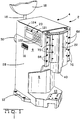
- FIGURE 1 is an isometric view of an electronically controlled crimping press having a slide ram, which is shown in a fully raised, home position;
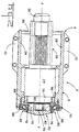
- FIGURE 2 is an enlarged top plan view of the press shown mainly in section;
- FIGURE 3 is an enlarged fragmentary view illustrating details of Figure 2;
- FIGURE 4 is an enlarged fragmentary, sectional view of the press, showing the slide ram in an intermediate position;
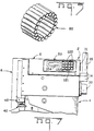
- FIGURE 5 is an enlarged isometric view of a bearing ring which is shown in Figures 2, 3 and 8;
- FIGURE 6 is an enlarged elevational view, shown partly in section, of the lower part of the press shown in Figure 1 and having fixed thereto a mounting plate for an electrical terminal applicator;
- FIGURE 7 is an enlarged fragmentary side view of the upper part press;
- FIGURE 8 is an enlarged front view, shown partly in section, of the upper part of the press;
- FIGURE 9 is an enlarged side view, shown partly in section, of the slide ram;
- FIGURE 10 is an enlarged front view of the slide ram;
- FIGURE 11 is an isometric view of one example of an electrical terminal applicator for the press;
- FIGURE 12 is a block schematic diagram illustrating an electronic control circuit arrangement for the press and for a lead making machine;
- FIGURE 13 is a graph illustrating the operation of the control circuit arrangement; and
- FIGURE 14 is a diagram of an eccentric assembly of the press, associated with the graph of Figure 13.
- The mechanical construction of the press will now be described with particular reference to Figures 1 to 10.
- An electronically controlled
crimping press 2, comprises, acast metal frame 4 having a generally rectangularram drive housing 6, apedestal 8 formed integrally therewith, and anapplicator mounting base 10 formed integrally with thepedestal 8, mountinglugs 12 projecting from opposite sides of the latter. There projects from the rear of thehousing 4, as shown in Figure 7, alug 14 supporting avertical shaft 16 carrying arotatable storage reel 18, part of which is shown in Figure 1, and about which is wound strip S (Figure 11) of electrical terminals T. Secured to one side of thehousing 6, is acontrol panel 20, for use in operating an electronic control circuit, which is described below and which is shown in Figure 12. - Arranged for vertical, reciprocating, sliding movement, in the forward part of the
housing 6, is aslide ram 22, which is connected, as best seen in Figure 2, by way of areduction gear box 24, to a three-phase, brushless, maintenance free, DC synchronouselectric motor 26. Themotor 26 is mounted in thehousing 6 with considerable clearance from itsside walls 28, in which are providedlouvers 31 for augmented ventilation of themotor 26. There is connected to the output shaft of themotor 26, at the opposite end of the shaft to thegear box 24, anincremental encoder 30 fixed to themotor 26. Thegear box 24 is secured to theside walls 28 by means ofscrews 88. - As shown in Figure 6, an
applicator mounting plate 32 provided withapplicator mounting lugs 34 is secured to thebase 10 by means ofscrews 36. Theslide ram 22 is provided at its lower end with anadaptor 40 for releasably securing theram 22, as shown in Figure 7, to acomplementary adaptor 42 of anelectrical terminal applicator 44, an example of which is shown in Figure 11. The applicator shown in Figure 11 is end feed applicator, comprising aram housing 46 containing anapplicator ram 47 terminating at its upper end in theadaptor 42 and at its lower end, in terminal crimping dies 48. Theapplicator 44 has a terminalstrip feeding device 50 for the strip S, comprising afeed finger 52 arranged to be driven in reciprocating motion by means of a piston andcylinder unit 54 to drive the strip S of electrical terminals along afeed track 56 towards aterminal crimping anvil 58 on anapplicator base 60 adapted to be secured to theplate 32 by means of thelugs 34. Such an applicator is described, for example, in US-A-3,184,950, which is incorporated herein by reference. - The
ram 22 is mounted to theside walls 28 of thehousing 6 by way of roller orball bearings 62 comprisingouter tracks 64 secured to theside walls 28 by means ofscrews 66, as best seen in Figure 3, andinner tracks 68 secured tolugs 69 extending along vertical margins of theram 22 by means ofscrews 70. Thetrack 64 on oneside wall 68 is laterally adjustable by means ofgrub screws 72, as will best be appreciated from Figure 8. As best seen in Figure 3, theram 22 is mounted in thebearings 62 bisected by its transverse, or horizontal, central axis X-X so that it does not tend to tilt forwardly or rearwardly during its vertical, reciprocating, sliding movement on thebearings 62. As best seen in Figures 9 and 10, theram 22 is formed with a substantially rectangular cross section,elongate guideway 74 opening into its rear face only, extending horizontally thereacross parallel to the axis X-X and which receives aneccentric assembly 76 for horizontal reciprocating movement as indicated by the arrows A, in Figure 3, at right angles to the axis of rotation Y-Y of the shaft of themotor 26, which axis is at right angles to the axis X-X. Theram 22 is formed withchannels 77 for oil for lubricating theguideway 74 and thebearings 62. Theeccentric assembly 76, comprises acentral stub shaft 78 which is mounted for rotation about its axis in aroller bearing ring 80 which is best seen in Figure 5 and which is in turn mounted in a circular crosssection bearing block 82 in the form of a roller, which is best seen in Figure 8. Theshaft 78, is arranged to be driven in rotation by reduction gearing (not shown) in thegearbox 24, and is mounted to anoutput shaft 79 thereof (as best seen in Figures 4 and 14), eccentrically with respect to said axis Y-Y which is also the axis of rotation of theoutput shaft 79. - As the
shaft 78 is rotated by the motor 25 by way of thereduction gear box 24,assembly 76 drives theram 22 through its vertical, reciprocating motion, the eccentricity of theassembly 76 being taken up by rolling movement thereof along theguideway 74; as will be apparent from a comparison of Figures 2 and 3, in which theram 22 is in its fully raised, or home, position, with Figure 4 in which theram 22 is in an intermediate position. Thus when theapplicator 44 is mounted to thepress 2, in the manner described above, thecrimping die 48 of theapplicator 44 is driven by theram 22 in reciprocating motion to crimp terminals T to leads inserted between thedie 48 and theanvil 58. Theencoder 30, serves incrementally to measure the angular position of theshaft 78 and thus the vertical position of theram 22, which is drive through one cycle of its reciprocating movement during each revolution of theshaft 78. The bearing block could be of rectangular, instead of circular, cross-section, arranged to slide, instead of roll, along theguideway 74. - It is important that the
press ram 22 should be returned to its home position, that is to say to its fully raised position (0° in Figure 14), with reasonable precision following each cycle its reciprocating movement because part, for example the feed finger, of an applicator on theplate 32, driven according to the vertical position the applicator ram will be incorrectly synchronized with the end positions of the applicator ram should the latter either overshoot, or undershoot with respect to its home position at the end of a crimping cycle. Also a significant overshoot of theram 22, could cause the applicator ram to obstruct the insertion of a lead between the crimping die and the crimping anvil of the applicator, at the beginning of a crimping cycle. Proper return of thepress ram 22 to its home position at the end of a cycle, is of enhanced importance where the applicator is part of a lead making machine having automatic lead insertion means which must be synchronized with the cycle of the applicator ram. Again, where the applicator is a stripper crimper, stripping means thereof must also be coordinated with the movement of the applicator ram. - A
circuit arrangement 89, for controlling thepress 2, so that theram 22 returns, with the required accuracy, to its top dead center, or home, position at the end of each cycle of the press, and for controlling the operation of auxiliary means of an applicator of the press and associated parts of a lead making machine of which the press is part, will now be described with a particular reference to Figures 12 to 14. - As shown in Figure 12, the
motor 26 which as mentioned above, is a maintenance free, brushless, three phase, synchronous, DC motor, comprises apermanent magnet 90, which is fixed toshaft 92 of themotor 26 and which is rotated by the field coils (not shown) thereof which are fed with phased DC pulses, PU, PV and PW, respectively, the speed of themotor 26 being a function of the pulse frequency. Themagnet 90 cooperates withHall effect sensors 94 each of which produces a pulse train PX, PY and PZ, respectively, the pulse frequency of which is a function of the speed rotation of theshaft 92, that is to say the motor speed. Three inlets U', V' and W', of themotor 26 are supplied with the pulses PU, PV and PW, respectively by a motordrive pulse generator 96 fed with direct current via a rectifying andsmoothing circuit 98 connected via a gangedswitch 100 to an alternatingcurrent filter 101 which is in turn connected to AC mains voltage by a further gangedswitch 102. The motordrive pulse generator 96 is controlled vialines digital logic circuit 104, by way of aninterface circuit 106, to vary the frequency of, or reverse the polarity of, the pulses PU, PV and PW or to supply a continuous pulse to a phase of themotor 26 to hold it stationary. Thecircuit 104 is connected to amain computer 108 by way of afirst optoisolator 110, thecomputer 108 having entered therein a desiredmotor speed program 112. Thecomputer 108 is also connected to alead making machine 114 by way of asecond optoisolator 116, in which machine thepress 2 is incorporated. Thecomputer 108 is supplied from the AC mains by way of a rectified andvoltage changer 118 and is also connected to thecontrol panel 20 by way of an array oflines 120. - Both the
sensors 94, and theincremental encoder 30 are connected to themotor control circuit 104 by way oflines circuit 104 comprises acomparator 109 which compares the outputs on thelines motor 26 and the angular position of itsshaft 92, respectively, with the desired motor speed registered in theprogram 112, the speed of themotor 26 being controlled by thecircuit 104 by way of thepulse generator 96 upon the basis of such comparison. In theory, themotor 26 could be brought to a halt when theram 22 is in its top dead center, or home position, only by comparison of the output of thesensors 94 with theprogram 112, but this could not be achieved with reasonable accuracy in practice by means of acircuit 104 of a kind which can be produced commercially at a reasonable cost. In the present case, however, the speed of themotor 26 as controlled upon the basis of a comparison between theprogram 12 and the frequency of the pulses PX, PY and PZ, tends to hunt, that is to say it becomes unstable, as theram 22 is moved towards its home position. At this stage however, the signals supplied by theincremental encoder 30 are effective in thecircuit 104 to supply control signals to thepulse generator 96 continually to return themotor 26 to the desired speed stipulated by theprogram 112. Figure 13 is a graph in which the ordinate represents the motor speed VL and the abscissa, the angular position AP of theshaft 78. It will be seen from the graph that as theram 22 descends towards the fully depressed position, that is to say the position at which the applicator ram crimps the terminal to the lead, the speed of themotor 26 rises linearly up to a point proximate to the 180° position of theshaft 78 and falls slightly as the crimping operation is carried out around that position. Thereafter the motor speed rises slightly and then falls again, as theshaft 78 moves towards its home position. As shown in Figure 13, theencoder 30 serves to linearlise the speed of themotor 26 between approximately the 200° to 300° angular positions theshaft 78.Lines 123 connecting theprogram 112 to thecircuit 104, by way of theoptoisolator 110 continually feed into thecircuit 104, the desired motor speed criteria for different angular positions of theshaft 78. - The
control panel 20 is provided with abank 121 oftouch screens 122, and anindicator screen 124 on which the computer causes to be displayed operating information for example that the press is ready for use or that there is a fault in a particular part of the system. - The
motor 26 is controlled throughout its rotation in order to halt theram 22 when it is at least approximately in its home position, at which time thecircuit 104 signals thepulse generator 96 to reverse the polarity of the pulses PU, PV and PW, no specific brake means for themotor 26 being needed. Respective ones of thetouch screens 122 may be actuable by the operator to cause thecomputer 108 to signal thepulse generator 96 by way of thecontrol circuit 104 to the following ends, for example: to start themotor 26; to stop themotor 26 by momentarily reversing the current supply thereto; to hold themotor 26 in its stopped position by applying a continuous current to one of its phases; to reverse themotor 26 to clear a jammed terminal; or to cause themotor 26 to crawl forwardly and rearwardly, by applying its feed pulses at reduced frequency in the appropriate senses, when the press is being set up. - The sense of rotation, of the
motor 26 is controlled by way oflines 125 between thecomputer 108 and thecircuit 104, themotor 26 is held in its stopped position by signals applied by thecomputer 108 tolines 127 between thecomputer 108 and thecircuit 104 and themotor 26 is controlled to crawl by way oflines 129 between thecomputer 108 and thecircuit 104. - A
clock pulse line 134 is provided between thecomputer 108 and thecontrol circuit 104 for the transmission of pulses for synchronizing thecomputer 108 therewith so that thepulse generator 96 is signalled to control themotor 26, only with a rapidity which is compatible with the following capacity of themotor 26. Themotor 26 is provided with atemperature sensor 132, connected vialines 134 to thecomputer 108 to cause it to actuate thecircuit 104 and hence thepulse generator 96, stop themotor 26 when its temperature exceeds a predetermined threshold. Thepulse generator 96 also has atemperature sensor 136 connected to theline 134 so that themotor 26 is stopped should thegenerator 96 become overheated. - When a strip of terminals is being manufactured, by means of a usual progressive strip forming process, the forming process may comprise means for removing from the strip, any terminal which has been found by sensing means of the forming press to be defective. For this reason, the strip of terminals on the
reel 18 of thepress 2 may have had one or more terminals removed therefrom, so that no terminal may be present on the anvil during a particular cycle of the applicator ram. If the lead making machine presents a lead to the applicator when no terminal is present on its anvil, then that lead will be wasted for this reason, thecircuit arrangement 89 is provided with missingterminal sensors computer 108 bylines optoisolator 110. If a missing terminal is detected upstream of the anvil, themain computer 108 signals the lead presenting means of thelead making machine 114, vialines optoisolator 116, to dwell during one cycle of operation so that no lead is presented to the applicator when there is no terminal on its anvil. Thecomputer 108 also signals thepress 2, to carry out an extra cycle during the dwell period of the lead presenting means, by way oflines 152, theoptoisolator 110, thecircuit 104 and thepulse generator 96, so that the feed finger of the applicator places the next following terminal of the strip on the anvil at the proper time. - The force required to turn the
reel 18 of thepress 2, varies as a function of the length of the terminal strip T that remains thereon, so that the force with which the feed finger of the applicator must advance the strip will similarly vary, whereby a terminal may be incorrectly positioned on the anvil, as a result of such variation. To avoid this disadvantage, the applicator is provided with anelectric motor 154 arranged to rotate a spool 156 to take up a length of interleavingpaper 158 with which the turns of a strip of terminals on a reel are customary separated. As the length of paper is taken up, the part of the strip of terminals extending from thereel 18 towards, the applicator is caused to sag slightly thereby to relieve the force that the feed finger needs to exert against the strip to advance it towards the anvil of the applicator.Strip sensors sensor 160, which actuates arelay 164 to close aswitch 166 to connect themotor 154 to the main supply, vialines 168. The motor accordingly starts and rotates thereel 118 by pulling on thepaper length 158 until said part of the terminal strip sags to an extent to activate thesensor 162 which actuates therelay 164 to open theswitch 166 to stop the motor 156. - When the terminals T are arranged in side or ladder strip form as shown in Figure 11, the terminals T of the strip S are connected to each other by carrier strip CS, from which the applicator shears a terminal T during each crimping operation. The carrier strips CS from which the terminals are shared are waste, and
shear blades 170, driven by anelectric motor 172, are provided for shearing the waste strips CS into easily disposable fragments F. If, however, the terminals are in end to end strip form, the applicator only shears out slugs connecting the terminals of the strip, so that theblades 70 are not needed. One of thetouch screens 122 is therefore actuable to instruct thecomputer 108 to bring themotor 172 into operation if, and when, it is needed, by way of theoptoisolator 110, and themotor control circuit 104 to which themotor 172 is connected by way oflines 174. - Others of the
touch screens 122 are actuable to control parts of, or peripheral equipment of, thelead making machine 114, in light of a particular lead making program, by way of thecomputer 108,lines 176 and theoptoisolator 116, for example to allow for the type of applicator to be used, for example a stripper crimper, or an end feed or a side feed applicator. - At least one set of
lines 178 is provided, running from thelead making machine 114, by way of theoptoisolator 116, thecomputer 108, theoptoisolator 110, afurther optoisolator 180 and theinterface circuit 106, to thepulse generator 96 for disabling thepulse generator 96 in the event of a fault, for example a terminal strip fault, or press breakdown. - A key operated shut-
down switch 182 is connected to theoptoisolator 180 by aline 184, and to thecomputer 108 via theoptoisolator 110, bylines 186, for disabling both thepulse generator 96 and thecomputer 108 whilst leaving itsprogram 112 intact, however. A guard operatedswitch 188, connected to themotor control circuit 104 by way of aline 190 is provided for opening theswitch 100 to cut-off power to thepulse generator 96, should a guard (not shown) of the press, be opened. - The
control circuit 104 is arranged to signal thecomputer 108 via theoptoisolator 116, by way oflines 192 when theeccentric assembly 76 has reached a point P1 (Figure 14) spaced angularly from the home position, 0°, of theram 22, for example by 90°, to cause thecomputer 108, in turn to signal thelead making machine 114, by way of theoptoisolator 116 andlines 194 to cause the lead presenting means thereof to withdraw a terminated lead from between the dies and anvil of the applicator, thereby to increase the speed of operation of thelead making machine 114, by the length of a sector S1 of the press cycle, that is to say by as much as a quarter.
Claims (6)
- A press comprising a drive electric motor (26) coupled to a slide ram (22) to drive it in reciprocating movement, by way of a reduction gear box (24) and a ram drive shaft (78) connected to an output shaft (79) of the gear box (24), eccentrically with respect to the axis of rotation (Y-Y) of the output shaft (79); wherein the drive shaft (78) is mounted for rotation in bearings (80) in a bearing block (82) received in an elongate guideway (74) formed in the slide ram (22) and extending at right angles to the direction of movement of the slide ram (22), whereby the eccentricity of the drive shaft (78) is taken up as the slide ram (22) is being driven by the motor (26), by movement of the bearing block (82) along the guideway (74); characterized in that the guideway (74) extends only partially through the thickness of the ram (22) and opens into its rear face.
- A press according to claim 1, characterized in that the axis of rotation of said output shaft (79) is coincident with that of the output shaft (92) of the motor (26).
- A press according to claim 1, characterized in that the slide ram (22) has a central axis (X-X) which is perpendicular to said axis of rotation (Y-Y) and parallel to said guideway (74), the ram (22) being mounted to slide in bearings (62) on opposite side walls (28) of the press (2) and which are bisected by said central axis (X-X).
- A press according to claim 3, characterized in that said bearings are ball or roller bearings (62) having outer tracks (64) secured to the side walls (28) and inner tracks (68) secured to lugs (69) extending along margins of the ram (22), one of said outer tracks (64) being adjustable towards and away from the other outer track (64).
- A press according to claim 1, 2, 3 or 4, characterized in that said bearing block is in the form of a roller (82) receiving a roller bearing ring (80), interposed between said roller (82) and drive shaft (78).
- A press according to claim 3 or 4, characterized in that said motor is a brushless synchronous electric motor (26), said axis of rotation (Y-Y) being coincident with the axis of rotation of the motor (26), the press (2) comprising a housing (4) in which the motor (26) is mounted with considerable clearance from said side walls (28).
Applications Claiming Priority (2)
| Application Number | Priority Date | Filing Date | Title |
|---|---|---|---|
| GB8914503 | 1989-06-23 | ||
| GB898914503A GB8914503D0 (en) | 1989-06-23 | 1989-06-23 | Eccentric press |
Publications (2)
| Publication Number | Publication Date |
|---|---|
| EP0404365A1 EP0404365A1 (en) | 1990-12-27 |
| EP0404365B1 true EP0404365B1 (en) | 1994-03-09 |
Family
ID=10658978
Family Applications (1)
| Application Number | Title | Priority Date | Filing Date |
|---|---|---|---|
| EP90305818A Expired - Lifetime EP0404365B1 (en) | 1989-06-23 | 1990-05-29 | Eccentric press |
Country Status (5)
| Country | Link |
|---|---|
| EP (1) | EP0404365B1 (en) |
| JP (1) | JP2954667B2 (en) |
| DE (1) | DE69007177T2 (en) |
| GB (1) | GB8914503D0 (en) |
| NO (1) | NO902787L (en) |
Families Citing this family (1)
| Publication number | Priority date | Publication date | Assignee | Title |
|---|---|---|---|---|
| CN103595170A (en) * | 2013-10-23 | 2014-02-19 | 中达电机股份有限公司 | End cover structure with outer cover |
Family Cites Families (3)
| Publication number | Priority date | Publication date | Assignee | Title |
|---|---|---|---|---|
| AT245939B (en) * | 1963-06-10 | 1966-03-25 | Konink Metaalfab V H J N Daald | Eccentric press |
| NL6405642A (en) * | 1964-05-21 | 1965-11-22 | ||
| DD132707A3 (en) * | 1977-01-26 | 1978-10-25 | Eberhard Ruediger | PISTON FEEDING FOR PRESSES, ESPECIALLY STAGE PRESSES |
-
1989
- 1989-06-23 GB GB898914503A patent/GB8914503D0/en active Pending
-
1990
- 1990-05-29 DE DE69007177T patent/DE69007177T2/en not_active Expired - Fee Related
- 1990-05-29 EP EP90305818A patent/EP0404365B1/en not_active Expired - Lifetime
- 1990-06-21 JP JP2163940A patent/JP2954667B2/en not_active Expired - Lifetime
- 1990-06-22 NO NO90902787A patent/NO902787L/en unknown
Also Published As
| Publication number | Publication date |
|---|---|
| JP2954667B2 (en) | 1999-09-27 |
| DE69007177D1 (en) | 1994-04-14 |
| EP0404365A1 (en) | 1990-12-27 |
| NO902787L (en) | 1990-12-27 |
| NO902787D0 (en) | 1990-06-22 |
| GB8914503D0 (en) | 1989-08-09 |
| JPH0332496A (en) | 1991-02-13 |
| DE69007177T2 (en) | 1994-09-29 |
Similar Documents
| Publication | Publication Date | Title |
|---|---|---|
| EP0404350B1 (en) | Press with control circuit arrangement | |
| US5129317A (en) | Press driven by an electric motor through reduction gearing | |
| US5033187A (en) | Electrical lead terminating installation | |
| EP0536804B1 (en) | Method of operating a press | |
| US5669257A (en) | Method of crimping terminal and apparatus for the same | |
| EP0139368B1 (en) | Terminal crimping apparatus | |
| EP0404364B1 (en) | Electrical lead terminating installation | |
| EP0350872A1 (en) | Motor control device for electric injection molding machine | |
| EP0404365A1 (en) | Eccentric press | |
| US20010047674A1 (en) | Method and apparatus for producing a crimp connection | |
| US4450946A (en) | Press speed control and indication system | |
| CN206535944U (en) | Screw rod servo terminal forming machine | |
| ES2117163T3 (en) | INJECTION DRIVE. | |
| US3873899A (en) | Automatic index and operating cycle regulator for a punch | |
| CN1261288C (en) | Numerical control shearer | |
| CN110666483A (en) | Automatic assembling device for stepping motor shell | |
| CN2198988Y (en) | Bracket system | |
| CN216027619U (en) | Bending machine for shutter blades | |
| EP0074250B1 (en) | Press speed control and indication system | |
| CN214934849U (en) | Automobile sensing line processing device | |
| CN223222221U (en) | A copper busbar anti-jump device for a copper busbar processing machine | |
| CN114226843B (en) | A flat-bed machine is driven to intelligence for processing of aluminium veneer | |
| CN212918268U (en) | Steel sheet welding frock | |
| JP2823866B2 (en) | Scrap cutting equipment | |
| CN212342455U (en) | Tool for putting coil into shell |
Legal Events
| Date | Code | Title | Description |
|---|---|---|---|
| PUAI | Public reference made under article 153(3) epc to a published international application that has entered the european phase |
Free format text: ORIGINAL CODE: 0009012 |
|
| AK | Designated contracting states |
Kind code of ref document: A1 Designated state(s): CH DE FR GB IT LI NL |
|
| 17P | Request for examination filed |
Effective date: 19901227 |
|
| 17Q | First examination report despatched |
Effective date: 19920630 |
|
| RAP1 | Party data changed (applicant data changed or rights of an application transferred) |
Owner name: THE WHITAKER CORPORATION |
|
| GRAA | (expected) grant |
Free format text: ORIGINAL CODE: 0009210 |
|
| AK | Designated contracting states |
Kind code of ref document: B1 Designated state(s): CH DE FR GB IT LI NL |
|
| REF | Corresponds to: |
Ref document number: 69007177 Country of ref document: DE Date of ref document: 19940414 |
|
| ITF | It: translation for a ep patent filed | ||
| ET | Fr: translation filed | ||
| PLBE | No opposition filed within time limit |
Free format text: ORIGINAL CODE: 0009261 |
|
| STAA | Information on the status of an ep patent application or granted ep patent |
Free format text: STATUS: NO OPPOSITION FILED WITHIN TIME LIMIT |
|
| 26N | No opposition filed | ||
| PGFP | Annual fee paid to national office [announced via postgrant information from national office to epo] |
Ref country code: NL Payment date: 19980324 Year of fee payment: 9 |
|
| PGFP | Annual fee paid to national office [announced via postgrant information from national office to epo] |
Ref country code: GB Payment date: 19980403 Year of fee payment: 9 |
|
| PGFP | Annual fee paid to national office [announced via postgrant information from national office to epo] |
Ref country code: FR Payment date: 19980508 Year of fee payment: 9 |
|
| PGFP | Annual fee paid to national office [announced via postgrant information from national office to epo] |
Ref country code: DE Payment date: 19980529 Year of fee payment: 9 |
|
| PGFP | Annual fee paid to national office [announced via postgrant information from national office to epo] |
Ref country code: CH Payment date: 19980709 Year of fee payment: 9 |
|
| PG25 | Lapsed in a contracting state [announced via postgrant information from national office to epo] |
Ref country code: GB Free format text: LAPSE BECAUSE OF NON-PAYMENT OF DUE FEES Effective date: 19990529 |
|
| PG25 | Lapsed in a contracting state [announced via postgrant information from national office to epo] |
Ref country code: LI Free format text: LAPSE BECAUSE OF NON-PAYMENT OF DUE FEES Effective date: 19990531 Ref country code: CH Free format text: LAPSE BECAUSE OF NON-PAYMENT OF DUE FEES Effective date: 19990531 |
|
| PG25 | Lapsed in a contracting state [announced via postgrant information from national office to epo] |
Ref country code: NL Free format text: LAPSE BECAUSE OF NON-PAYMENT OF DUE FEES Effective date: 19991201 |
|
| REG | Reference to a national code |
Ref country code: CH Ref legal event code: PL |
|
| GBPC | Gb: european patent ceased through non-payment of renewal fee |
Effective date: 19990529 |
|
| PG25 | Lapsed in a contracting state [announced via postgrant information from national office to epo] |
Ref country code: FR Free format text: LAPSE BECAUSE OF NON-PAYMENT OF DUE FEES Effective date: 20000131 |
|
| NLV4 | Nl: lapsed or anulled due to non-payment of the annual fee |
Effective date: 19991201 |
|
| PG25 | Lapsed in a contracting state [announced via postgrant information from national office to epo] |
Ref country code: DE Free format text: LAPSE BECAUSE OF NON-PAYMENT OF DUE FEES Effective date: 20000301 |
|
| REG | Reference to a national code |
Ref country code: FR Ref legal event code: ST |
|
| PG25 | Lapsed in a contracting state [announced via postgrant information from national office to epo] |
Ref country code: IT Free format text: LAPSE BECAUSE OF NON-PAYMENT OF DUE FEES;WARNING: LAPSES OF ITALIAN PATENTS WITH EFFECTIVE DATE BEFORE 2007 MAY HAVE OCCURRED AT ANY TIME BEFORE 2007. THE CORRECT EFFECTIVE DATE MAY BE DIFFERENT FROM THE ONE RECORDED. Effective date: 20050529 |