EP0404222B1 - Process for manufacturing a plastic crate by injection moulding, and plastic crate manufactured by said process - Google Patents
Process for manufacturing a plastic crate by injection moulding, and plastic crate manufactured by said process Download PDFInfo
- Publication number
- EP0404222B1 EP0404222B1 EP90201503A EP90201503A EP0404222B1 EP 0404222 B1 EP0404222 B1 EP 0404222B1 EP 90201503 A EP90201503 A EP 90201503A EP 90201503 A EP90201503 A EP 90201503A EP 0404222 B1 EP0404222 B1 EP 0404222B1
- Authority
- EP
- European Patent Office
- Prior art keywords
- handle
- crate
- mould cavity
- cavity part
- mould
- Prior art date
- Legal status (The legal status is an assumption and is not a legal conclusion. Google has not performed a legal analysis and makes no representation as to the accuracy of the status listed.)
- Expired - Lifetime
Links
- 238000001746 injection moulding Methods 0.000 title claims abstract description 5
- 238000000034 method Methods 0.000 title claims description 27
- 238000004519 manufacturing process Methods 0.000 title claims description 4
- 239000000463 material Substances 0.000 claims abstract description 50
- 239000007788 liquid Substances 0.000 claims abstract description 9
- 230000015572 biosynthetic process Effects 0.000 claims abstract description 7
- 238000002347 injection Methods 0.000 claims description 16
- 239000007924 injection Substances 0.000 claims description 16
- 238000001816 cooling Methods 0.000 claims description 7
- 239000011344 liquid material Substances 0.000 claims description 3
- 238000005192 partition Methods 0.000 claims description 2
- 230000001413 cellular effect Effects 0.000 description 2
- 239000011347 resin Substances 0.000 description 2
- 229920005989 resin Polymers 0.000 description 2
- 230000004927 fusion Effects 0.000 description 1
- 239000011796 hollow space material Substances 0.000 description 1
- 238000001175 rotational moulding Methods 0.000 description 1
Images
Classifications
-
- B—PERFORMING OPERATIONS; TRANSPORTING
- B29—WORKING OF PLASTICS; WORKING OF SUBSTANCES IN A PLASTIC STATE IN GENERAL
- B29C—SHAPING OR JOINING OF PLASTICS; SHAPING OF MATERIAL IN A PLASTIC STATE, NOT OTHERWISE PROVIDED FOR; AFTER-TREATMENT OF THE SHAPED PRODUCTS, e.g. REPAIRING
- B29C45/00—Injection moulding, i.e. forcing the required volume of moulding material through a nozzle into a closed mould; Apparatus therefor
- B29C45/17—Component parts, details or accessories; Auxiliary operations
- B29C45/1703—Introducing an auxiliary fluid into the mould
- B29C45/1704—Introducing an auxiliary fluid into the mould the fluid being introduced into the interior of the injected material which is still in a molten state, e.g. for producing hollow articles
-
- B—PERFORMING OPERATIONS; TRANSPORTING
- B65—CONVEYING; PACKING; STORING; HANDLING THIN OR FILAMENTARY MATERIAL
- B65D—CONTAINERS FOR STORAGE OR TRANSPORT OF ARTICLES OR MATERIALS, e.g. BAGS, BARRELS, BOTTLES, BOXES, CANS, CARTONS, CRATES, DRUMS, JARS, TANKS, HOPPERS, FORWARDING CONTAINERS; ACCESSORIES, CLOSURES, OR FITTINGS THEREFOR; PACKAGING ELEMENTS; PACKAGES
- B65D25/00—Details of other kinds or types of rigid or semi-rigid containers
- B65D25/28—Handles
- B65D25/30—Hand holes
-
- B—PERFORMING OPERATIONS; TRANSPORTING
- B29—WORKING OF PLASTICS; WORKING OF SUBSTANCES IN A PLASTIC STATE IN GENERAL
- B29L—INDEXING SCHEME ASSOCIATED WITH SUBCLASS B29C, RELATING TO PARTICULAR ARTICLES
- B29L2031/00—Other particular articles
- B29L2031/712—Containers; Packaging elements or accessories, Packages
- B29L2031/7134—Crates, e.g. for bottles
Definitions
- the present invention relates to a process for manu- facturing a plastic crate by injection mouding, said crate having a bottom and upright side walls, at least one of the side walls being provided near the top side with a handle bounded at the bottom side by a handle opening, the handle having a substantially closed outer wall which is integral with the remainder of the crate, the process comprising the steps of injecting a liquid plastic material into a mould cavity corresponding to the shape of the crate to be manufactured, until the mould cavity is substantially filled, cooling the injected plastic material, and opening the mould.
- the known process has the disadvantage that the crate can only be manufactured from an expanded or foamed resin and that for manufacturing a double-walled crate a relati- vely large amount of material is needed. Moreover, with the known process the possible shapes of a crate are limited.
- the object of the invention is to provide a process which does not have these disadvantages.
- This object is achieved by a process of the abovemen- tioned type which is characterized in that a gas under pressure is injected into the stream of liquid plastic material for the formation of the handle, in such a way that at least one cavity is formed in said liquid material and that said material is blown against the wall of the mould cavity part for the handle, the gas pressure is maintained during the cooling of said material, and the gas pressure is released just before opening of the mould.
- crates By means of the process according to the invention many types of crates can be manufactured having relatively thin walls and having one or more handles which are sufficiently strong to carry the weight of the full crate and which lie comfortably in the hand.
- the quantity of material required for the handle can remain limited.
- the mould used in the process can be relatively simple. This permits optimum fitting of cooling channels in the mould, so that the cycle time can be relatively short.
- the gas holds the walls of the handle pressed against the inside wall of the mould part concerned, which optimizes the cooling process.
- the invention also relates to a plastic crate manufactured by injection moulding having a bottom and upright side walls, at least one of the side walls being provided near the top side with a handle bounded at the bottom side by a handle opening, the handle having a substantially closed outer wall which is integral with the remainder of the crate, characterized in that the handle is hollow, the wall of the handle enclosing at least one cavity which is connected to the environment by a bore of relatively small size in the wall of the handle.
- US-A-3,506,154 discloses a plastic crate having handles which are hollow. However, this crate is manufactured by a rotational moulding process and the wall of each handle does not enclose a cavity which is connected to the environment by a bore of relatively small size in the wall of the handle.
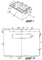
- the crate shown in Figure 1 comprises a bottom 1, two long upright side walls 2 and 3, and two short upright walls 4 and 5.
- the side walls of the crate are made double-walled, the inner wall of the double wall being removed locally, so that openings 6, 7 are produced in the side walls 2, 3 and 4, 5.
- the two opposite short side walls 4, 5 are each provided at the top side with a handle 8, 9, which at the bottom side is bounded by handle opening 10, 11.
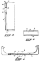
- the handles 8 and 9 are made hollow with a substantially closed wall 12 (see Figs. 3 and 4).
- each of the handles 8, 9 is formed by injecting gas under pressure into the stream of liquid plastic material for the formation of a handle 8, 9, in such a way that at least one cavity 13 is produced in said liquid material, and said material is blown against the wall of the mould cavity part for the handle. During the cooling of this material the gas pressure is maintained, and the gas pressure is released just before the mould is opened.
- the handles 8, 9 thus formed are subsequently integral with the remainder of the crate and can be designed with rounded edges 14, 15.
- the injection of gas under pressure into the stream of liquid plastic material for forming a handle 8, 9 can take place through a gas injection aperture which is provided in such a way in the mould cavity part for the handle in question that at the moment that the mould cavity part for the handle is not yet entirely filled with material this aperture is situated in the core of the material which has flowed in at the time. At that moment gas under pressure is injected through the gas injection aperture into the liquid plastic material.
- the material for each of the handles 8, 9 is introduced from the two sides into the mould cavity part for the handle 8, 9 in question, and the injection of gas under pressure takes place at the point where the material flows merge in the mould cavity part in question, at the moment that these material flows merge, and before the mould cavity part is completely filled.
- the gas injection aperture in this case lies approximately at the centre of the outside wall of the handle 8, 9.
- the material for each of the handles 8, 9 is introduced from one of the two sides into the mould cavity part for the handle 8, 9 in question, and the injection of the gas under pressure takes place near the side of the particular mould cavity part where the material is being introduced, at the moment that the front of the material flow has just passed the gas injection point.
- the material for forming the handles 8, 9 then merges near the handles with the material of the remainder of the crate.
- the bore in each handle 8, 9 is then situated near one of the sides of the handle, for example at a point which is indicated by reference number 17 in Figure 2.
- the material for each of the handles 8, 9 is introduced from the two sides into the mould cavity part for the handle 8, 9 in question, and the injection of gas under pressure takes place near the sides of the particular mould cavity part where the material is introduced, at the moment that the fronts of the two material flows have just passed the gas injection points.
- the fronts of the two material flows meeting each other approximately at the centre of the handle are now pressed with great force against each other, thus causing a very intense fusion.
- a crate is formed in which the two handles 8, 9 each contain two cavities which are separated from each other by means of a partition situated approximately in the centre of the handle, and in which each cavity is connected to the environment by means of its own bore.
- the two bores near the ends of the handle 8, 9 are indicated by the reference numbers 17 and 18.
- the invention is described for a crate of a specific shape.
- the invention is not, however, limited to such a crate and can be used just as well for crates or trays of a different shape and of different dimensions, with or without a lattice.
Landscapes
- Engineering & Computer Science (AREA)
- Mechanical Engineering (AREA)
- Manufacturing & Machinery (AREA)
- Details Of Rigid Or Semi-Rigid Containers (AREA)
- Injection Moulding Of Plastics Or The Like (AREA)
- Processing And Handling Of Plastics And Other Materials For Molding In General (AREA)
- Moulds For Moulding Plastics Or The Like (AREA)
- Cartons (AREA)
- Sealing Battery Cases Or Jackets (AREA)
Abstract
Description
- The present invention relates to a process for manu- facturing a plastic crate by injection mouding, said crate having a bottom and upright side walls, at least one of the side walls being provided near the top side with a handle bounded at the bottom side by a handle opening, the handle having a substantially closed outer wall which is integral with the remainder of the crate, the process comprising the steps of injecting a liquid plastic material into a mould cavity corresponding to the shape of the crate to be manufactured, until the mould cavity is substantially filled, cooling the injected plastic material, and opening the mould.
- Such a process is disclosed in US-A-3,506,154. In this known process an expanded or foamed resin is injected directly into a mould cavity. That part of the cellular material directly touching the mould cavity walls will be immediately chilled and form a high density non-porous skin, whereas the expanded material in the region between the mould cavity walls will remain a low density material. In this manner the hollow space between the outer and inner walls forming the bottom and the side walls will automati- cally include a cellular material.
- The known process has the disadvantage that the crate can only be manufactured from an expanded or foamed resin and that for manufacturing a double-walled crate a relati- vely large amount of material is needed. Moreover, with the known process the possible shapes of a crate are limited.
- The object of the invention is to provide a process which does not have these disadvantages.
- This object is achieved by a process of the abovemen- tioned type which is characterized in that a gas under pressure is injected into the stream of liquid plastic material for the formation of the handle, in such a way that at least one cavity is formed in said liquid material and that said material is blown against the wall of the mould cavity part for the handle, the gas pressure is maintained during the cooling of said material, and the gas pressure is released just before opening of the mould.
- By means of the process according to the invention many types of crates can be manufactured having relatively thin walls and having one or more handles which are sufficiently strong to carry the weight of the full crate and which lie comfortably in the hand.
- Through the process according to the invention the quantity of material required for the handle can remain limited. The mould used in the process can be relatively simple. This permits optimum fitting of cooling channels in the mould, so that the cycle time can be relatively short. The gas holds the walls of the handle pressed against the inside wall of the mould part concerned, which optimizes the cooling process.
- Preferred embodiments according to the process according to the invention are described in the process subclaims.
- The invention also relates to a plastic crate manufactured by injection moulding having a bottom and upright side walls, at least one of the side walls being provided near the top side with a handle bounded at the bottom side by a handle opening, the handle having a substantially closed outer wall which is integral with the remainder of the crate, characterized in that the handle is hollow, the wall of the handle enclosing at least one cavity which is connected to the environment by a bore of relatively small size in the wall of the handle.
- US-A-3,506,154 discloses a plastic crate having handles which are hollow. However, this crate is manufactured by a rotational moulding process and the wall of each handle does not enclose a cavity which is connected to the environment by a bore of relatively small size in the wall of the handle.
- The invention will now be explained in greater detail with reference to the following example of an embodiment shown in the drawings, in which:
- Figure 1 is a view in perspective of a possible embodiment of a crate according to the invention;
- Figure 2 is a side view on an enlarged scale of the crate of Figure 1 in the direction of the arrow II;
- Figure 3 is a view of a side wall of the crate of Figure 1, provided with a handle, in a section along the line III-III in Figure 2;
- Figure 4 is a top view of a side wall of the crate of Figure 1, provided with a handle, partially in a section along the line IV-IV in Figure 2; and
- Figure 5 shows a detail V of Figure 4 on an enlarged scale.
- The crate shown in Figure 1 comprises a
bottom 1, two longupright side walls upright walls openings 6, 7 are produced in theside walls short side walls - The crate described above, with the exception of the handles, is moulded in a conventional manner by liquid plastic material being injected into a mould cavity in a mould corresponding to the shape of the crate, until the mould cavity is substantially filled, the injected plastic material is cooled, and the mould is then opened. According to the invention, each of the handles 8, 9 is formed by injecting gas under pressure into the stream of liquid plastic material for the formation of a handle 8, 9, in such a way that at least one
cavity 13 is produced in said liquid material, and said material is blown against the wall of the mould cavity part for the handle. During the cooling of this material the gas pressure is maintained, and the gas pressure is released just before the mould is opened. The handles 8, 9 thus formed are subsequently integral with the remainder of the crate and can be designed withrounded edges - The injection of gas under pressure into the stream of liquid plastic material for forming a handle 8, 9 can take place through a gas injection aperture which is provided in such a way in the mould cavity part for the handle in question that at the moment that the mould cavity part for the handle is not yet entirely filled with material this aperture is situated in the core of the material which has flowed in at the time. At that moment gas under pressure is injected through the gas injection aperture into the liquid plastic material.
- The formation of a cavity in a product made of plastic material by the injection of gas under pressure into the material is known per se, but not for the formation of a hollow handle on a crate. It is certainly not known to use this technique for the formation of a hollow part in a product made of plastic material at or in the vicinity of a flow seam, as is the case with the present invention.
- According to a particular embodiment of the process according to the invention, the material for each of the handles 8, 9 is introduced from the two sides into the mould cavity part for the handle 8, 9 in question, and the injection of gas under pressure takes place at the point where the material flows merge in the mould cavity part in question, at the moment that these material flows merge, and before the mould cavity part is completely filled. The gas injection aperture in this case lies approximately at the centre of the outside wall of the handle 8, 9.
- With this embodiment of the process according to the invention a crate of the type shown in the figures is obtained, the hollow handles 8, 9 each being provided with at least one
bore 16 by means of which thecavity 13 in the handle 8, 9 is connected to the environment. - According to another embodiment of the process according to the invention, the material for each of the handles 8, 9 is introduced from one of the two sides into the mould cavity part for the handle 8, 9 in question, and the injection of the gas under pressure takes place near the side of the particular mould cavity part where the material is being introduced, at the moment that the front of the material flow has just passed the gas injection point. The material for forming the handles 8, 9 then merges near the handles with the material of the remainder of the crate. The bore in each handle 8, 9 is then situated near one of the sides of the handle, for example at a point which is indicated by
reference number 17 in Figure 2. - According to yet another embodiment of the process according to the invention, the material for each of the handles 8, 9 is introduced from the two sides into the mould cavity part for the handle 8, 9 in question, and the injection of gas under pressure takes place near the sides of the particular mould cavity part where the material is introduced, at the moment that the fronts of the two material flows have just passed the gas injection points. The fronts of the two material flows meeting each other approximately at the centre of the handle are now pressed with great force against each other, thus causing a very intense fusion. With this embodiment of the process according to the invention, a crate is formed in which the two handles 8, 9 each contain two cavities which are separated from each other by means of a partition situated approximately in the centre of the handle, and in which each cavity is connected to the environment by means of its own bore. In Figure 2 the two bores near the ends of the handle 8, 9 are indicated by the
reference numbers - In the example of an embodiment the invention is described for a crate of a specific shape. The invention is not, however, limited to such a crate and can be used just as well for crates or trays of a different shape and of different dimensions, with or without a lattice.
Claims (8)
- Process for manufacturing a plastic crate by injection moulding, said crate having a bottom (1) and upright side walls (2 to 5), at least one of the side walls (4, 5) being provided near the top side with a handle (8, 9) bounded at the bottom side by a handle opening (10, 11), the handle (8, 9) having a substantially closed outer wall (12) which is integral with the remainder of the crate, the process comprising the steps of injecting a liquid plastic material into a mould cavity corresponding to the shape of the crate to be manufactured, until the mould cavity is substantially filled, cooling the injected plastic material, and opening the mould, characterizing in that a gas under pressure is injected into the stream of liquid plastic material for the formation of the handle (8, 9), in such a way that at least one cavity (13) is formed in said liquid material and that said material is blown against the wall of the mould cavity part for the handle, the gas pressure is maintained during the cooling of said material, and the gas pressure is released just before opening of the mould.
- Process according to claim 1, characterized in that the material of the handle (8, 9) is introduced from the two sides into the mould cavity part for the handle, and the injection of the gas under pressure takes place at the point where the material flows merge in the mould cavity part in question, at the moment that these material flows merge, and before the mould cavity part is completely filled.
- Process according to claim 1, characterized in that the material for the handle (8, 9) is introduced from one of the two sides into the mould cavity part for the handle, and the injection of the gas under pressure takes place near the side of the particular mould cavity part where the material is being introduced, at the moment that the front of the material flow has just passed the gas injection point.
- Process according to claim 1, characterized in that the material for the handle (8, 9) is introduced from the two sides into the mould cavity part for the handle, and the injection of the gas under pressure takes place near the sides of the particular mould cavity part where the material is being introduced, at the moment that the fronts of the material flows have just passed the gas injection point.
- Plastic crate manufactured by injection moulding having a bottom (1) and upright side walls (2 to 5), at least one of the side walls (4, 5) being provided near the top side with a handle (8, 9) bounded at the bottom side by a handle opening (10, 11), the handle (8, 9) having a substantially closed outer wall (12) which is integral with the remainder of the crate, characterized in that the handle (8, 9) is hollow, the wall (12) of the handle enclosing at least one cavity (13) which is connected to the environment by a bore (16; 17, 18) of relatively small size in the wall of the handle.
- Crate according to claim 5, characterized in that the handle contains only one cavity (13), and the bore (16) is situated approximately in the centre or near one of the sides of the handle (8, 9).
- Crate according to claim 5, characterized in that the handle contains two cavities which are separated from each other by means of a partition lying approximately in the centre of the handle, and each cavity is connected to the environment by means of its own bore (17, 18).
- Crate according to claim 7, characterized in that the bores (17, 18) are situated near the sides of the handle (8, 9).
Applications Claiming Priority (2)
| Application Number | Priority Date | Filing Date | Title |
|---|---|---|---|
| NL8901550A NL8901550A (en) | 1989-06-20 | 1989-06-20 | METHOD FOR MANUFACTURING AN PLASTIC CRATE AND PLASTIC CRATE MANUFACTURED BY THIS METHOD |
| NL8901550 | 1989-06-20 |
Publications (2)
| Publication Number | Publication Date |
|---|---|
| EP0404222A1 EP0404222A1 (en) | 1990-12-27 |
| EP0404222B1 true EP0404222B1 (en) | 1993-10-13 |
Family
ID=19854861
Family Applications (1)
| Application Number | Title | Priority Date | Filing Date |
|---|---|---|---|
| EP90201503A Expired - Lifetime EP0404222B1 (en) | 1989-06-20 | 1990-06-11 | Process for manufacturing a plastic crate by injection moulding, and plastic crate manufactured by said process |
Country Status (6)
| Country | Link |
|---|---|
| EP (1) | EP0404222B1 (en) |
| AT (1) | ATE95752T1 (en) |
| DE (2) | DE69003882T2 (en) |
| DK (1) | DK0404222T3 (en) |
| ES (1) | ES2047241T3 (en) |
| NL (1) | NL8901550A (en) |
Families Citing this family (6)
| Publication number | Priority date | Publication date | Assignee | Title |
|---|---|---|---|---|
| DE4035497C2 (en) * | 1990-11-08 | 1994-08-11 | Peguform Werke Gmbh | Device for the production of transport boxes, in particular bottle boxes |
| DE4327060A1 (en) * | 1993-08-12 | 1995-02-16 | Wilhelm Goetz | Process for producing a hollow element |
| DE9414117U1 (en) * | 1994-08-31 | 1994-12-15 | Liedtke Acryl GmbH, 85229 Markt Indersdorf | Food box, especially for bananas |
| DE19525000C1 (en) * | 1995-07-08 | 1997-01-30 | Theysohn Friedrich Fa | Injection mold for the production of a box made of plastic |
| EP3560676A1 (en) * | 2018-04-25 | 2019-10-30 | Formosa Saint Jose Corporation | Production method of a roof box and roof box structure |
| JP7491541B2 (en) * | 2019-08-20 | 2024-05-28 | 岐阜プラスチック工業株式会社 | Transport container |
Family Cites Families (5)
| Publication number | Priority date | Publication date | Assignee | Title |
|---|---|---|---|---|
| US3334767A (en) * | 1964-12-28 | 1967-08-08 | Cornelius Co | Bottle carrier for 6-packs |
| US3506154A (en) * | 1968-07-08 | 1970-04-14 | Laidlaw Corp | Plastic case for milk bottles |
| GB1371240A (en) * | 1971-07-02 | 1974-10-23 | Gpg Holdings Ltd | Containers |
| NL7906528A (en) * | 1979-08-30 | 1981-03-03 | Wavin Bv | Double walled plastic crate - has side with handgrip opening contg. snap in insert to cover sharp edges around opening |
| JPH0788025B2 (en) * | 1987-04-28 | 1995-09-27 | 三菱瓦斯化学株式会社 | Manufacturing method of synthetic resin molded product having uneven wall reinforcement structure |
-
1989
- 1989-06-20 NL NL8901550A patent/NL8901550A/en not_active Application Discontinuation
-
1990
- 1990-06-11 DE DE90201503T patent/DE69003882T2/en not_active Expired - Fee Related
- 1990-06-11 EP EP90201503A patent/EP0404222B1/en not_active Expired - Lifetime
- 1990-06-11 DK DK90201503.1T patent/DK0404222T3/en active
- 1990-06-11 AT AT90201503T patent/ATE95752T1/en not_active IP Right Cessation
- 1990-06-11 ES ES90201503T patent/ES2047241T3/en not_active Expired - Lifetime
- 1990-06-16 DE DE9006785U patent/DE9006785U1/en not_active Expired - Lifetime
Also Published As
| Publication number | Publication date |
|---|---|
| DE69003882T2 (en) | 1994-02-24 |
| EP0404222A1 (en) | 1990-12-27 |
| ATE95752T1 (en) | 1993-10-15 |
| ES2047241T3 (en) | 1994-02-16 |
| DK0404222T3 (en) | 1993-11-15 |
| NL8901550A (en) | 1991-01-16 |
| DE69003882D1 (en) | 1993-11-18 |
| DE9006785U1 (en) | 1990-08-23 |
Similar Documents
| Publication | Publication Date | Title |
|---|---|---|
| US4340990A (en) | Object intended to be held in the hand, in particular a suitcase handle, and a process for manufacturing same | |
| US3705931A (en) | Method for blow molding and compression molding thermoplastic material | |
| US3746204A (en) | Hollow double-wall article | |
| JPS57117938A (en) | Two-color molding method | |
| US5000904A (en) | Device and process for production of blown three-handled container | |
| US20060266915A1 (en) | Tray mold | |
| GB1264608A (en) | ||
| US4382058A (en) | Process for forming a single-walled blow molded hinged container | |
| GB2144074A (en) | Method of manufacturing a hollow plastics article | |
| CA2046784A1 (en) | Method for producing molded article of thermoplastic resin | |
| US4056138A (en) | Flexible plastic container | |
| EP0404222A1 (en) | Process for manufacturing a plastic crate by injection moulding, and plastic crate manufactured by said process | |
| US4486379A (en) | Process for forming an integral hinged single wall blow molded container | |
| US4453911A (en) | Blow mold | |
| JPS6482910A (en) | Molding method of molded product having hollow part | |
| JPS5630828A (en) | Injection blow molding of hollow vessel with handle | |
| EP0486107A1 (en) | Plastic crate with partially hollow handle | |
| DE3065867D1 (en) | Plastics crate or tray comprising injection moulding points, method and mould for manufacturing such a crate or tray | |
| EP0374519A3 (en) | A method of producing plastic tanks for washing machines and a tank thus obtained | |
| EP1030767B1 (en) | Flat or semi-flat element including a frame | |
| EP0714744A3 (en) | Process for the production of structural thermoinsulating elements and elements so obtained | |
| JPH03248822A (en) | Injection molding method | |
| JP3066770B2 (en) | Manufacturing method of housing panel | |
| CA1111218A (en) | Modular die set for blow molding containers | |
| RU2017616C1 (en) | Mold for manual shaping of plastics |
Legal Events
| Date | Code | Title | Description |
|---|---|---|---|
| PUAI | Public reference made under article 153(3) epc to a published international application that has entered the european phase |
Free format text: ORIGINAL CODE: 0009012 |
|
| AK | Designated contracting states |
Kind code of ref document: A1 Designated state(s): AT BE CH DE DK ES FR GB GR IT LI LU NL SE |
|
| 17P | Request for examination filed |
Effective date: 19901126 |
|
| 17Q | First examination report despatched |
Effective date: 19920327 |
|
| GRAA | (expected) grant |
Free format text: ORIGINAL CODE: 0009210 |
|
| AK | Designated contracting states |
Kind code of ref document: B1 Designated state(s): AT BE CH DE DK ES FR GB GR IT LI LU NL SE |
|
| PG25 | Lapsed in a contracting state [announced via postgrant information from national office to epo] |
Ref country code: IT Free format text: LAPSE BECAUSE OF FAILURE TO SUBMIT A TRANSLATION OF THE DESCRIPTION OR TO PAY THE FEE WITHIN THE PRE;WARNING: LAPSES OF ITALIAN PATENTS WITH EFFECTIVE DATE BEFORE 2007 MAY HAVE OCCURRED AT ANY TIME BEFORE 2007. THE CORRECT EFFECTIVE DATE MAY BE DIFFERENT FROM THE ONE RECORDED.SCRIBED TIME-LIMIT Effective date: 19931013 Ref country code: GR Free format text: LAPSE BECAUSE OF FAILURE TO SUBMIT A TRANSLATION OF THE DESCRIPTION OR TO PAY THE FEE WITHIN THE PRESCRIBED TIME-LIMIT Effective date: 19931013 |
|
| REF | Corresponds to: |
Ref document number: 95752 Country of ref document: AT Date of ref document: 19931015 Kind code of ref document: T |
|
| REG | Reference to a national code |
Ref country code: DK Ref legal event code: T3 |
|
| REF | Corresponds to: |
Ref document number: 69003882 Country of ref document: DE Date of ref document: 19931118 |
|
| ET | Fr: translation filed | ||
| REG | Reference to a national code |
Ref country code: ES Ref legal event code: FG2A Ref document number: 2047241 Country of ref document: ES Kind code of ref document: T3 |
|
| PLBI | Opposition filed |
Free format text: ORIGINAL CODE: 0009260 |
|
| PG25 | Lapsed in a contracting state [announced via postgrant information from national office to epo] |
Ref country code: GB Effective date: 19940611 |
|
| PLBI | Opposition filed |
Free format text: ORIGINAL CODE: 0009260 |
|
| PLBI | Opposition filed |
Free format text: ORIGINAL CODE: 0009260 |
|
| EPTA | Lu: last paid annual fee | ||
| 26 | Opposition filed |
Opponent name: OBERLAND PLASTIC GMBH Effective date: 19940513 |
|
| 26 | Opposition filed |
Opponent name: OBERLAND PLASTIC GMBH Effective date: 19940513 Opponent name: MELEA LIMITED Effective date: 19940707 |
|
| 26 | Opposition filed |
Opponent name: OBERLAND PLASTIC GMBH Effective date: 19940513 Opponent name: ALLIBERT EQUIPMENT Effective date: 19940711 Opponent name: MELEA LIMITED Effective date: 19940707 |
|
| NLR1 | Nl: opposition has been filed with the epo |
Opponent name: OBERLAND PLASTIC GMBH. |
|
| NLR1 | Nl: opposition has been filed with the epo |
Opponent name: MELEA LIMITED |
|
| NLR1 | Nl: opposition has been filed with the epo |
Opponent name: ALLIBERT EQUIPMENT |
|
| EAL | Se: european patent in force in sweden |
Ref document number: 90201503.1 |
|
| GBPC | Gb: european patent ceased through non-payment of renewal fee |
Effective date: 19940611 |
|
| RAP2 | Party data changed (patent owner data changed or rights of a patent transferred) |
Owner name: WAVIN B.V. |
|
| RDAH | Patent revoked |
Free format text: ORIGINAL CODE: EPIDOS REVO |
|
| APAC | Appeal dossier modified |
Free format text: ORIGINAL CODE: EPIDOS NOAPO |
|
| APAE | Appeal reference modified |
Free format text: ORIGINAL CODE: EPIDOS REFNO |
|
| REG | Reference to a national code |
Ref country code: CH Ref legal event code: PUE Owner name: WAVIN B.V. TRANSFER- WAVIN TREPAK BV |
|
| NLS | Nl: assignments of ep-patents |
Owner name: WAVIN TREPAK BV |
|
| REG | Reference to a national code |
Ref country code: FR Ref legal event code: TP |
|
| REG | Reference to a national code |
Ref country code: ES Ref legal event code: PC2A |
|
| BECA | Be: change of holder's address |
Free format text: 970123 *WAVIN TREPAK B.V.:BRUCHTERWEG 88, 7772 BJ HARDENBERG |
|
| PLBQ | Unpublished change to opponent data |
Free format text: ORIGINAL CODE: EPIDOS OPPO |
|
| PLAB | Opposition data, opponent's data or that of the opponent's representative modified |
Free format text: ORIGINAL CODE: 0009299OPPO |
|
| R26 | Opposition filed (corrected) |
Opponent name: MELEA LIMITED * 940711 ALLIBERT EQUIPMENT * Effective date: 19940707 |
|
| NLXE | Nl: other communications concerning ep-patents (part 3 heading xe) |
Free format text: PAT. BUL. 19/94 THE OPPOSITION OF OBERLAND PLASTIC GMBH HAS BEEN WITHDRAWN |
|
| PGFP | Annual fee paid to national office [announced via postgrant information from national office to epo] |
Ref country code: AT Payment date: 19990623 Year of fee payment: 10 |
|
| PGFP | Annual fee paid to national office [announced via postgrant information from national office to epo] |
Ref country code: LU Payment date: 19990705 Year of fee payment: 10 |
|
| APAC | Appeal dossier modified |
Free format text: ORIGINAL CODE: EPIDOS NOAPO |
|
| PLBO | Opposition rejected |
Free format text: ORIGINAL CODE: EPIDOS REJO |
|
| PLBN | Opposition rejected |
Free format text: ORIGINAL CODE: 0009273 |
|
| STAA | Information on the status of an ep patent application or granted ep patent |
Free format text: STATUS: OPPOSITION REJECTED |
|
| PG25 | Lapsed in a contracting state [announced via postgrant information from national office to epo] |
Ref country code: LU Free format text: LAPSE BECAUSE OF NON-PAYMENT OF DUE FEES Effective date: 20000611 Ref country code: AT Free format text: LAPSE BECAUSE OF NON-PAYMENT OF DUE FEES Effective date: 20000611 |
|
| 27O | Opposition rejected |
Effective date: 20000529 |
|
| NLR2 | Nl: decision of opposition | ||
| PGFP | Annual fee paid to national office [announced via postgrant information from national office to epo] |
Ref country code: CH Payment date: 20010621 Year of fee payment: 12 Ref country code: FR Payment date: 20010621 Year of fee payment: 12 Ref country code: BE Payment date: 20010621 Year of fee payment: 12 |
|
| PGFP | Annual fee paid to national office [announced via postgrant information from national office to epo] |
Ref country code: SE Payment date: 20010625 Year of fee payment: 12 Ref country code: DK Payment date: 20010625 Year of fee payment: 12 Ref country code: DE Payment date: 20010625 Year of fee payment: 12 |
|
| PGFP | Annual fee paid to national office [announced via postgrant information from national office to epo] |
Ref country code: ES Payment date: 20010627 Year of fee payment: 12 |
|
| PGFP | Annual fee paid to national office [announced via postgrant information from national office to epo] |
Ref country code: NL Payment date: 20010630 Year of fee payment: 12 |
|
| PG25 | Lapsed in a contracting state [announced via postgrant information from national office to epo] |
Ref country code: ES Free format text: LAPSE BECAUSE OF NON-PAYMENT OF DUE FEES Effective date: 20020612 Ref country code: SE Free format text: LAPSE BECAUSE OF NON-PAYMENT OF DUE FEES Effective date: 20020612 |
|
| PG25 | Lapsed in a contracting state [announced via postgrant information from national office to epo] |
Ref country code: CH Free format text: LAPSE BECAUSE OF NON-PAYMENT OF DUE FEES Effective date: 20020630 Ref country code: BE Free format text: LAPSE BECAUSE OF NON-PAYMENT OF DUE FEES Effective date: 20020630 Ref country code: LI Free format text: LAPSE BECAUSE OF NON-PAYMENT OF DUE FEES Effective date: 20020630 |
|
| PG25 | Lapsed in a contracting state [announced via postgrant information from national office to epo] |
Ref country code: DK Free format text: LAPSE BECAUSE OF NON-PAYMENT OF DUE FEES Effective date: 20020731 |
|
| BERE | Be: lapsed |
Owner name: *WAVIN TREPAK B.V. Effective date: 20020630 |
|
| PG25 | Lapsed in a contracting state [announced via postgrant information from national office to epo] |
Ref country code: DE Free format text: LAPSE BECAUSE OF NON-PAYMENT OF DUE FEES Effective date: 20030101 Ref country code: NL Free format text: LAPSE BECAUSE OF NON-PAYMENT OF DUE FEES Effective date: 20030101 |
|
| REG | Reference to a national code |
Ref country code: DK Ref legal event code: EBP |
|
| EUG | Se: european patent has lapsed | ||
| REG | Reference to a national code |
Ref country code: CH Ref legal event code: PL |
|
| PG25 | Lapsed in a contracting state [announced via postgrant information from national office to epo] |
Ref country code: FR Free format text: LAPSE BECAUSE OF NON-PAYMENT OF DUE FEES Effective date: 20030228 |
|
| NLV4 | Nl: lapsed or anulled due to non-payment of the annual fee |
Effective date: 20030101 |
|
| REG | Reference to a national code |
Ref country code: FR Ref legal event code: ST |
|
| REG | Reference to a national code |
Ref country code: ES Ref legal event code: FD2A Effective date: 20030711 |
|
| APAH | Appeal reference modified |
Free format text: ORIGINAL CODE: EPIDOSCREFNO |