EP0403965A2 - MS-MS-flight time mass spectrometer - Google Patents
MS-MS-flight time mass spectrometer Download PDFInfo
- Publication number
- EP0403965A2 EP0403965A2 EP90111293A EP90111293A EP0403965A2 EP 0403965 A2 EP0403965 A2 EP 0403965A2 EP 90111293 A EP90111293 A EP 90111293A EP 90111293 A EP90111293 A EP 90111293A EP 0403965 A2 EP0403965 A2 EP 0403965A2
- Authority
- EP
- European Patent Office
- Prior art keywords
- ions
- ion
- time
- reflector
- mass spectrometer
- Prior art date
- Legal status (The legal status is an assumption and is not a legal conclusion. Google has not performed a legal analysis and makes no representation as to the accuracy of the status listed.)
- Granted
Links
Images


Classifications
-
- H—ELECTRICITY
- H01—ELECTRIC ELEMENTS
- H01J—ELECTRIC DISCHARGE TUBES OR DISCHARGE LAMPS
- H01J49/00—Particle spectrometers or separator tubes
- H01J49/004—Combinations of spectrometers, tandem spectrometers, e.g. MS/MS, MSn
-
- H—ELECTRICITY
- H01—ELECTRIC ELEMENTS
- H01J—ELECTRIC DISCHARGE TUBES OR DISCHARGE LAMPS
- H01J49/00—Particle spectrometers or separator tubes
- H01J49/26—Mass spectrometers or separator tubes
- H01J49/34—Dynamic spectrometers
- H01J49/40—Time-of-flight spectrometers
Definitions
- the invention relates to time-of-flight mass spectrometers with an ion source for generating a pulsed primary ion beam, with a device for pulsed, locally delimited influencing of the ions and with an ion reflector to compensate for time-of-flight differences of the ions of the same mass.
- MS-MS techniques in mass spectrometry allow secondary mass selection after a preferred mass from the variety of ions that is generated in the ion source has already been selected with a primary mass selector. These primarily selected ions experience an interaction of various kinds, (eg excitation by shocks, light, etc.), which leads to fragmentation, the secondary fragments can be examined by a further mass analysis.
- MS-MS techniques can be used to study molecular decay kinetics, to elucidate molecular structures and to analyze unknown molecules; They represent one of the most complex, but also the most information-rich methods in these areas.
- MS-MS mass spectrometry So-called double-focusing devices, which consist of a combination of magnetic and electrostatic mass analyzers, are usually used for MS-MS mass spectrometry.
- MS-MS devices as well as their slope, MS-MS-MS devices, have reached a certain limit of their developability both in terms of their price / performance ratio and in terms of their technical capabilities.
- the so-called reflectron time-of-flight spectrometers overcome one of the greatest disadvantages of conventional time-of-flight mass spectrometers: the low mass resolution.
- a resolution (50% valley) of 5000 as standard (without readjustment) and of 10,000 without serious problems can be achieved (e.g. from: Boesl et al., Anal. Instrum. 16 (1987) 151).
- Even a resolution of 35,000 has already been achieved (T. Bergmann, T.P. Martin, H. Schaber Rev. Sci. Instrum. 60 (1989) 347).
- the outstanding advantage of time-of-flight mass analyzers their extraordinarily high transmission and thus detection sensitivity, is almost unaffected.
- the resonant laser excitation serves for the ionization of molecules with the help of a multi-photon (mostly two-photon) absorption about a resonant intermediate state.
- a multi-photon mostly two-photon
- the inclusion of a molecule-specific, resonant optical transition already enables substance-selective ionization and thus a first step towards MS-MS methods.
- resonant laser excitation is also characterized by great flexibility: on the one hand, an exceptionally gentle ionization is possible (see, for example, Grotemeyer et al., Org. Mass Spectrom.
- Fragmentation can be achieved, which can be varied from the generation of a few fragments with high involvement of metastable decays to extremely hard fragmentation (see, for example, Boesl et al., J. Chem. Phys. 72 (1980) 4327 and Chem. Phys. Lett. 87 ( 1982) 1).
- the present invention is therefore based on the object to provide a device composed of simple components with various options in which, after ionization and before a final time-of-flight mass analysis, a further mass selection and / or a secondary fragmentation can take place, the mass resolution, the trans mission and the sensitivity of detection are not inferior to those of known devices.
- the ion source is designed in such a way that all ions of the same mass which are generated at the same time but at different locations in the ion source and therefore have different kinetic energies are located at a location focus of 2nd order , arrive at the same time that a device is provided at the location focus with which the physical state of the ions can be subjected to at least one of the following changes in pulses, namely change in the momentum, change in the quantum mechanical state of the electron shell, chemical reaction or fragmentation, each of which results from the primary ion beam, a secondary ion beam with new physical properties is generated, and that the ion reflector is designed in such a way that, with the corresponding operating mode, it effects time focusing of secondary ions of the same mass and the primary ions are masked out.
- the location focus in particular of the 2nd or higher order, a spatial point of optimal energy correction is available in which a very high primary mass resolution is possible.
- a secondary mass spectrum with the most favorable starting conditions is therefore provided by a secondary access exactly in this location focus.
- the type of secondary interaction initially does not matter; there is free choice in this regard.
- the time-focused ion reflector enables optimum mass resolution of the secondary mass spectrum obtained in this way, in particular if it is matched to the secondary ion masses of interest.
- the MS-MS time-of-flight mass spectrometer according to the present invention has the advantages over conventional MS-MS devices of very high transmission and thus great detection sensitivity and very high speed.
- Commercial Reflectron time-of-flight spectrometers can be converted to an MS-MS device with minor modifications; the essential additional costs arise only through the selected, secondary access method and are far below the purchase price of the source device.
- high transmission and detection sensitivity are also intrinsic properties of the method, as is speed: Secondary mass spectra can be carried out in the sub-millisecond range without losses in transmission or mass resolution. A combination with almost any access method, such as laser excitation, electron, ion, molecular and atomic beam or gas cells for shock activation is possible.
- the exact definition of the location focus ie the point of optimal energy correction of the primary ions leaving the ion source, is an essential prerequisite for the time-of-flight mass spectrometer according to the invention. While energy corrections of the first order have at most been implemented in the location focus, maintaining the distance relationships between the diaphragms and the corresponding potential relationships in claim 2 presents an ion source that enables energy correction of the second order.
- the particles to be ionized can be provided either simply by introducing gas into the ion source, or by evaporating the particles in the ion source itself. The latter method is also suitable for the investigation of solid substances.
- the particles to be examined are introduced into the ion source by means of an atomic or molecular beam, so that the part to be ionized Chen are only in a narrowly limited area, which allows an exact definition of the ion site.
- the atomic or molecular beam can cross the axis of symmetry of the diaphragms either substantially at right angles between the first and the second diaphragm of the ion source at a distance from the second diaphragm.
- the atomic or molecular beam enters the ion source collinearly to the axis of symmetry of the diaphragms through the first diaphragm, so that the structures for generating the atomic or molecular beam cannot be attached to the side of the mass spectrometer, but rather as an extension of its axis.
- Another advantage of this arrangement is that the particles that have not yet been ionized have a beam characteristic in the direction of the later ion beam.
- the particles to be examined can be ionized in the ion source either by photoeffect, by particle collisions or by field ionization.
- photoionization takes place, it is possible to keep the residual energy in the molecular ion to a minimum during the ionization process. It is a "gentle" method of ionization, in which even sensitive large molecules can be ionized without bursting.
- the cheapest is the use of a light beam from an incoherent source, in particular a UV source, for example a mercury vapor lamp for the continuous generation of high light output, or commercially available flash lamps.
- pulsed or continuous laser beams are used for the photoionization of the particles to be examined.
- the extraordinarily high frequency sharpness for laser light enables a high atom- or molecule-specific selectivity of photoionization. With it can quite selectively select only certain particles from a particle mixture offered in the ion source.
- pulsed lasers are used, the temporal characteristics of which are impressed on the pulsed ion beam.
- Another advantage of using lasers is the high power density that can be achieved, the possibility of a very sharp spatial bundling of laser beams and thus a very precise definition of the ion source, as well as the utilization of the frequency sharpness of the laser light with regard to the optical excitation of the particles to be examined.
- the particles to be examined are ionized by collisions using a beam of charged particles.
- This particle beam can either be an electron beam which is inexpensive and simple, e.g. high beam intensities and a good spatial beam definition can be achieved by means of a hot cathode and simple electron optics.
- the impact ionization takes place with the aid of an ion beam, which enables the mass spectrometric investigation of ion impact processes in the ion source.
- the point of ion formation is particularly well defined at the point of intersection of the two rays.
- the pulse characteristic of the ion beam is generated by pulsed voltages on the diaphragms of the ion source, so that a continuous supply of the to investigating particles and continuous ionization is possible.
- the potentials are statically applied to the diaphragms, which enables considerably simpler electronics for the voltage supply to the diaphragms, but requires a pulsed ionizing beam.
- the potentials applied to the diaphragms of the ion source can be set separately in embodiments of the invention.
- a control device which automatically adjusts the potential U b at the second aperture at given distances a, b, c and given potential U 1 at the first aperture.
- an ion detector with a flat impact surface is provided at a distance c in the direction of flight of the ions behind the third aperture of the ion source on the trajectory of the ions, with which the position of the location focus can be determined precisely.
- the ion detector is arranged such that it can be moved out of the trajectory of the ions by means of a mechanical displacement device, so that the properties of the location focus can either be exploited by recording a mass spectrum in the location focus or, after the adjustment of the location focus has been completed, the ion detector is moved out of the ion beam , and a secondary interaction can take place at the location focus.
- the secondary access to the ion beam at the location focus takes place modulo a defined time delay compared to the time of generation of the ion pulses in the ion source.
- the ions at the location focus are influenced in a strictly localized manner.
- the location focus is the starting point for a secondary mass spectrum.
- the interaction triggering pulse is synchronized with the primary ion pulse from the ion source.
- the ions are influenced by building up a pulsed electric field which is transverse to the ion beam direction and which causes a selective deflection of ions in a specific propagation time window from the primary ion beam direction.
- a pulsed electric field which is transverse to the ion beam direction and which causes a selective deflection of ions in a specific propagation time window from the primary ion beam direction.
- the transverse electrical field is generated by means of a mesh network. If the mesh network is fine enough, access to the ion beam is limited in space, and there is the possibility of time modulation of the secondary access via the changes in the electrical potential applied to the mesh network.
- the mesh network consists of two comb-like structures, the teeth of which consist of very fine wires, the teeth of the comb-like structures lying opposite one another in the center grip without touching and all teeth belonging to a comb-like structure are connected to each other in an electrically conductive manner.
- the electrical fields generated by the two comb-like structures cancel out at a very short distance in front of and behind the mesh, so that there is no unwanted interference of the ion beam by fields that extend far into space, as are typical for conventional grids, uncontrollable interference cause.
- voltage pulses are applied to the two comb-like structures, which are complementary to the potential U Potential applied to the third diaphragm of the ion source, that is to say they have the same amplitudes, the same pulse durations but opposite polarities. This can either cause the elimination of certain undesirable ion masses or a short time window for the passage of special ions, e.g. for targeted further secondary fragmentation.
- the secondary interaction in the location focus can take place by optical excitation, in particular with a laser beam. This can cause photodissociation and subsequent fragmentation of the primary ions.
- Optical excitation offers the advantage of being able to be tuned very precisely to a specific electronic transition and thus extremely high mass selectivity, and on the other hand is particularly gentle as a "soft" excitation method, so that even metastable states of larger molecules can be excited without first destroying them . On the other hand, it is variable from very soft to very hard Fragmentation and thus a variation of secondary mass spectra possible.
- the secondary interaction takes place in the location focus in the form of an ion shock excitation.
- the colliding particles come either from an electron beam or another ion beam that crosses the spatial focus perpendicular to the beam axis of the primary ions.
- the generation of an electron beam is particularly simple and inexpensive and does not require any complex optics.
- a second ion beam on the other hand, physical scattering experiments can be carried out in the location focus.
- the primary ions can either be brought into an excited state or can be broken up into smaller molecular fragments with sufficient energy.
- the ions are influenced with the aid of pulses which, owing to their short duration, ensure a sharp temporal, energetic and thus mass-specific selection of the primary ions to be influenced.
- the pulse duration can be virtually infinitely long, but then the selection of the primary ions to be excited is controlled by a sharply defined energy of the exciting particles or photons, by exciting very specific energy levels of the electron shell of these ions.
- the physical state of the ions is additionally influenced in the region of the location focus, either by optical excitation of the ions by means of a laser beam or by shock excitation means of an electron beam, an additional ion beam or an atomic or molecular beam.
- This enables the acquisition of secondary mass spectra of very special ion masses that were previously selected in the location focus by a first access.
- the interaction of the primary ion beam can also be provided in a collision gas cell before access in the location focus. A secondary mass spectrum of the ions leaving the collision cell can then be recorded by successively displacing the time window selected in the location focus relative to the time of origin of a primary ion pulse in the ion source.
- the post-acceleration of the ions is provided after the location focus.
- the drastic decrease in the kinetic energy of the ion fragments after fragmentation, which would have a negative effect on the mass resolution of the spectrometer, can thus be partially compensated for.
- a fourth diaphragm after the location focus is provided in the ion beam, which is electrically connected to the third diaphragm in the ion source via a tubular shield which encloses a field-free space.
- the post-acceleration is then brought about by a fifth aperture, which, viewed in the direction of flight of the ions, sits on the ion beam axis after the fourth aperture and lies at the ground potential of the time-of-flight spectrometer.
- an ion reflector is provided after the secondary interaction zone, which has one reflector end plate and several brake fields arranged at a distance in front on a common axis of symmetry contains defining brake electrodes, the reflector end plate being slidably arranged along the axis of symmetry of the ion reflector and, when the reflector end plate is displaced, the electrical potential applied to it is tracked in such a way that the electric field strength between the reflector end plate and the brake electrode lying first is not changed.
- Such an ion reflector initially serves to compensate for the time-of-flight differences of ions of the same mass but different initial energies, and thus to improve the mass resolution.
- the displaceable end plate makes it possible to mask out the ions of the primary beam: these have a higher kinetic energy than all fragment ions that are secondary to the primary ions, so that these primary ions have the greatest depth of penetration into the ion reflector. If you move the reflector end plate towards the incoming ion beam until the primary ions hit the plate and are thus removed from the ion beam, the ion reflector only leaves the low-energy secondary ions created due to the secondary access. These can now be detected undisturbed by the relatively high intensity of the primary beam with high resolution. By pushing the reflector end plate further towards the last brake electrode, ions with lower kinetic energy are also hidden. In this operating mode, the ion reflector can thus be used as an energy selector for recording secondary mass spectra.
- the easiest way to track the electrical potential of the reflector end plate when it is displaced is by means of a sliding contact.
- electronic voltage tracking is provided.
- an elec Tronic circuit provided, which changes the potentials of the other brake electrodes and the reflector end plate in the event that a potential on one of the brake electrodes is changed in such a way that the original relationships of the potentials to one another are retained before the change. This automatically maintains the optimal setting of the ion reflector once it is found, even when the position of the reflector end plate changes.
- the aperture openings of the brake electrodes are each provided with a network or a grid which serves as potential shielding and for producing parallel equipotential surfaces.
- a front panel with a larger opening diameter than that of the brake electrodes is provided. The front panel is then at the ground potential of the time-of-flight mass spectrometer and enables a controlled extraction of the electric fields from the brake electrodes into the space in front of the ion reflector, and thus a controlled steering of the ions arriving in and out of the ion reflector.
- the ions are normally deflected by the ion reflector from their original flight direction by an angle of more than 90 ° but less than 180 °.
- the axis of symmetry of the ion reflector is collinear with the direction of flight of the incoming ions, ie the ion beam is reflected back in itself.
- the ion detector sits on the ion beam axis between the ion reflector and the ion source and has an opening concentric to the ion beam axis for the passage of the incoming ions. This arrangement enables a very compact construction of the time-of-flight mass spectrometer.
- an optimal time focus for ions with less than the average kinetic energy of the ions is achieved by reducing the potentials applied to the brake electrodes and the reflector end plate.
- a secondary mass spectrum, in particular for molecular ions fragmented on the flight path, can thus be generated by tuning the fields and observing them in a fixed time fixed.
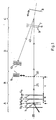
- the MS-MS time-of-flight mass spectrometer shown schematically in FIG. 1 comprises an ion source A, a secondary interaction zone B, an ion reflector C, in which the incident ion beam is reflected by an angle of more than 90 °, and a field-free ion drift distance D with an ion detector 10 for detecting the ions. All components are located within an evacuable housing, not shown.
- the ion source A has at least two accelerating pulsed or unpulsed electrical fields which are generated with at least three diaphragms: an ion-repelling first diaphragm 1, an ion-attracting second diaphragm 2 and a post-accelerating third diaphragm 3.
- the diaphragms 2 and 3 have an opening for the passage of the accelerated ions.
- Separately adjustable voltages can be applied to all three diaphragms, namely the potential U 1 to the first diaphragm 1, the potential U b + U 0 to the second diaphragm 2 and the potential U 0 to the third diaphragm 3.
- U0 is identical to the ground potential of the equipment.
- the particles to be ionized are provided by introducing gas into the ion source or by evaporating the particles within the ion source.
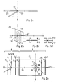
- the ionization of the particles to be examined in the ion source takes place in the embodiments shown in FIGS. 1 and 2e by means of a beam irradiated perpendicular to the axis of symmetry 20 of the diaphragm arrangement between the first diaphragm 1 and the second diaphragm 2 at a distance a from the second diaphragm 2 5.
- the beam 5 can be either a laser beam, an electron beam or an ion beam.
- the particles to be examined are then ionized either by absorption of photon energy in the electron shell or by particle collision.
- a beam of incoherent light in particular from a UV source, is used instead of the laser beam.
- the ionizing beam 5 perpendicularly crosses the beam 4 of the particles to be ionized on the axis of symmetry 20 and is focused on the crossing point.
- the pulse behavior of the primary ion beam 25 generated in the ion source is caused by a correspondingly pulsed ionizing beam 5.
- the ionizing beam 5 can also be irradiated continuously over time, the pulse behavior of the primary ion beam 25 then being impressed by pulsed electrical fields which are generated by applying corresponding potentials to the diaphragms 1, 2, 3.
- the Ionization of the particles to be examined caused by strong electric fields.
- the point of origin of the primary ions which in the exemplary embodiment shown is located on the axis of symmetry 20 between the first diaphragm 1 and the second diaphragm 2 at a distance a from the second diaphragm 2, can be changed by correspondingly shifting the beams 4 and 5.
- the distance b between aperture 2 and 3 is fixed in the exemplary embodiment shown, but can be kept variable in other embodiments, e.g. by means of a second orifice 2 which can be displaced in parallel, but then the distance a of the point of origin of the primary ions from the second orifice 2 also changes accordingly.
- a decisive feature of all embodiments of the present invention is the exploitation of the fact that ion sources with pulsed ion generation have a so-called location focus, which in the exemplary embodiment shown is located on the axis of symmetry 20 of the diaphragm arrangement at a distance c in the direction of the primary ion beam 25 according to FIG third aperture 3 is located.
- the location focus 30 is therefore a spatial point of optimal energy correction.
- the order and thus the quality of this correction depends on the type of ion source. With a one-stage ion source (only apertures 1 and 2) you can achieve a 1st order correction, with a two-stage ion source (like the one described above) a 2nd order correction. So far, even for multi-stage ions only the first order location focus is observed.
- the second-order location focus is used for the first time, which is derived below:
- the latter term (x k ) contributes not only to an energy blur but also to a time blur ("turn-around-time"), which must be taken into account separately.
- both the 1st order and the 2nd order terms must disappear in the above equation. From this condition, the relationships result for the quantities a, b, and c (see FIG.
- the longest possible flight distance c e.g. 10 to 20 cm
- a mass resolution of 500 to 1000 can thus already be achieved in such a location focus 30.
- such a location focus of the 2nd order is generated by a suitable choice of the aperture distances in the ion source A and by applying suitable potentials U1, U b and U0 to the apertures 1, 2, 3.
- a suitable ion detector 11 with a flat impingement surface is used for exact adjustment of the location focus 30 to a defined distance c, which can be achieved by varying the distance a of the origin of the ions from the second aperture 2 and the voltages at the apertures 1 and 2; this detector can be brought into the ion trajectory of the primary ion beam 25 by means of a mechanical displacement device and removed therefrom for MS-MS measurements.
- An electronic control device (not shown) is provided for automatically tracking the potential U b according to equation (II.) At a given potential U 1 and given distances a, b, c.
- the ion reflector C shown in FIG. 1 consists of a two-stage arrangement, namely the brake electrodes 6 and 7 defining a brake field and the reflector end plate 8, which together with the second brake electrode 7 seen in the direction of the incident ion beam defines a reflector field.
- the brake electrodes 6, 7 are designed as pinholes.
- the reflector end plate 8 is mounted so that it can be pushed into or out of the reflector. The voltage on this end plate is adjusted so that the field strength between Brake electrode 7 and reflector end plate 8 is not changed.
- the brake electrodes 6 and 7 have an opening several centimeters in size, which is either provided with a network for generating parallel aquipotential surfaces; or they are operated without networks, but then with a front panel 9, which is on the device mass of the time-of-flight mass spectrometer.
- the voltages required for such reflectors correspond to the values known from the literature.
- the axis of symmetry 40 of the ion reflector C can both, as shown in FIG. 1, have an angle to the direction of ion flight, as well as be collinear with it. In the latter case, however, a special ion detector is required (see below).
- the field-free ion drift distance D is simply formed by a sufficiently long, empty vacuum tube between a secondary interaction zone B and the ion reflector C, in accordance with known arrangements.
- Only a suitable ion detector 10 e.g. multichannel plate detector
- the ion detector 10 is located at the end of the ion trajectory, as close as possible to the secondary interaction zone B.
- the ion detector 10 is located on the incident ion flight direction with a concentric opening in the middle for the Passage of the ions coming from the ion source A and the secondary interaction zone B.
- the secondary interaction zone B contains the location focus 30 and is the heart of the MS-MS time-of-flight mass spectrometer.
- the focus 12 of a second laser pulse with selected wavelength and intensity is placed precisely in the location focus 30.
- This laser pulse can optionally be replaced by other pulsed, locally sharp access methods (eg electron beam). Varies If the time delay between the primary generation of ions in the ion source A and the secondary access in the location focus 30, the individual ions of different weights are selectively excited according to their different flight times t ges and can therefore also be selectively fragmented by photodissociation. If the pulse length is only short enough and the focus 12 is only small enough (for example 0.1 mm), the maximum mass resolution possible in the location focus 30 can be obtained. Secondary access is therefore responsible for both secondary mass selection and secondary fragmentation.
- the ion reflector C is optimally corrected for the kinetic energy of the primary ions in the ion beam 25 and the second laser is not switched on, a usual primary mass spectrum is obtained.
- the voltage at the ion reflector C must now be continuously reduced, the ratio of the voltages at the brake electrodes 6, 7 and the reflector end plate 8 (and possibly the front panel 9) being retained .
- the entire ion reflector C is thus optimally corrected for decreasing ion energies.
- the kinetic energy of a molecular ion in relation to the mass of the fragments is distributed among them; secondary fragments with smaller mass therefore also have smaller kinetic energies.
- the energy correction of the ion level is thus coordinated with the decreasing masses of the secondary fragment ions.
- the ion reflector C with a displaceable reflector end plate 8 and time window works as a tunable energy analyzer and thus, according to what has been said above about the fragment energies, as an analyzer for the masses of the secondary fragment ions.
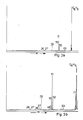
- 3b-d show such secondary mass spectra, the ordinate being the intensity of the incident ions measured on the ion detector 10 and the abscissa the voltage of the reflector end plate 8 calibrated in ion masses m.
- 3a shows a primary laser time-of-flight spectrum of benzene, in which the intensity of the first laser was chosen such that, in addition to the ionization, a partial fragmentation of the benzene ions also took place.
- FIG. 3b only the molecular ions in the location focus were detected, excited and fragmented by a suitable delay of the second laser; the secondary mass spectrum can be seen here.
- Fig. 3c only the fragment ions C4H4 + were selectively fragmented in the location focus 30, in Fig.
- the movable reflector end plate 8 is provided.
- the voltages at the ion reflector C can thus be set to optimal energy correction; then the reflector end plate 8 is pushed so far into the reflector field that the point of reversal of the primary ions lies exactly on it.
- the reflector end plate 8 In order to leave the reflector field and thus the energy correction unaffected, the reflector end plate 8 must always be at a voltage which corresponds exactly to the equipotential surface of its respective position; In embodiments, this can be done by means of a sliding contact (not shown) or electronic voltage tracking.
- the secondary intervention consists in a special mesh network 23, which in turn is located precisely in the location focus 30.
- This mesh network 23 consists of two comb-like structures 13 and 14, the "teeth" of which engage in the center without touching one another.
- the "teeth” consist of the finest possible wires; all "teeth” belonging to a comb are electrically connected to one another; their distances are 0.3 mm and smaller, or 0.15 mm or smaller from the "teeth" of the other comb.
- Complementary complementary voltage pulses ⁇ U (same amplitude, same length, opposite sign) are best applied to the two combs, so that on the one hand ions that fly between the teeth at the right time sense a transverse electric field and are deflected laterally, so that but on the other hand, at a very short distance from the mesh network 23, the pulsed fields already cancel each other out.
- FIG. 2e represents to some extent a combination of the embodiments from FIGS. 2a and 2b.
- a secondary mass spectrum can only be obtained sequentially and not with a single laser pulse.
- the fact is used that a two-stage ion reflector can still correct 20% energy blur, that a mass resolution of 5000 is easily achieved.
- the fragment ions are accelerated after the location focus 30.
- the kinetic energy of the ions at the location focus 30 may only be a fraction of the final kinetic ion energy.
- the ion source A with the diaphragms 1, 2 and 3, the mesh network 23 in the local focus 30 and an additional, final fourth diaphragm 15 are placed at an increased potential U0.
- the post-acceleration then takes place between the fourth orifice 15 and a fifth orifice 16 which is at ground potential.
- a tube 17 which is at the same potential as the diaphragms 3 and 15 and corresponds to the reference potential of the mesh network 23.
- the mesh network 23 is attached in the location focus 30; selected primary ions are selected with high mass resolution.
- the focus 18 of a second laser or another pulsed access for example electron beam or ion beam, is adjusted to the ion beam leaving the mesh on the axis of symmetry 20. If the voltage pulse on the mesh network 23 and the second laser pulse 18 or, in the case of embodiments, a different access pulse are precisely synchronized with the flight time of the primary ions of defined mass to be examined, a secondary mass spectrum of these ions is obtained.
- the mesh network 23 can also be replaced by the laser focus 18 (or other pulsed access methods); then, however, metastable ion decays that take place in front of the location focus 30 can disrupt the secondary mass spectrum of the selected ion.
- the secondary access can also consist of a continuous interaction, e.g. a continuous electron beam, molecular or atomic beam or a collision gas cell. The latter must then be installed in front of the mesh and the post-acceleration as close as possible behind the mesh.
- the secondary mass spectrum can also be divided into two or more mass ranges, the energy correction of the reflector only having to be optimized on one of these ranges and thus only on 10%, 5% etc. energy deviation.
- the energy correction of the reflector only having to be optimized on one of these ranges and thus only on 10%, 5% etc. energy deviation.
- a “metastable mass spectrum” here means the mass spectrum of all productions from the metastable decay of a selected precursor ion that has arisen in the ion source. This metastable decay is usually induced by the additional excitation of the primary ions at the ionization site, for example by further absorption of a photon by laser 1 in the primary ion. A suggestion, e.g. by laser 2 is then not necessary. In order to record "metastable mass spectra", only laser 2 is switched off.
Abstract
Description
Die Erfindung betrifft Flugzeit-Massenspektrometer mit einer Ionenquelle zur Erzeugung eines gepulsten primären Ionenstrahles, mit einer Vorrichtung zur gepulsten, örtlich scharf begrenzten Beeinflussung der Ionen sowie mit einem Ionenreflektor zum Ausgleich von Flugzeitdifferenzen der Ionen gleicher Masse.The invention relates to time-of-flight mass spectrometers with an ion source for generating a pulsed primary ion beam, with a device for pulsed, locally delimited influencing of the ions and with an ion reflector to compensate for time-of-flight differences of the ions of the same mass.
MS-MS-Techniken in der Massenspektrometrie erlauben eine sekundäre Massenselektion, nachdem mit einem primären Massenselektor bereits eine bevorzugte Masse aus der Vielfalt von Ionen, die in der Ionenquelle entsteht, ausgewählt wurde. Erfahren diese primär selektierten Ionen eine Wechselwirkung verschiedenster Art, (z.B. Anregung durch Stöße, Licht, etc.), die zu einer Fragmentierung führt, so können die sekundären Fragmente durch eine weitere Massenanalyse untersucht werden. Solche MS-MS-Techniken können zu Untersuchungen molekularer Zerfallskinetik, zur Aufklärung von molekularen Strukturen und zur Analyse unbekannter Moleküle eingesetzt werden; sie stellen auf diesen Gebieten eine der komplexesten, aber auch informationsreichsten Methoden dar.MS-MS techniques in mass spectrometry allow secondary mass selection after a preferred mass from the variety of ions that is generated in the ion source has already been selected with a primary mass selector. These primarily selected ions experience an interaction of various kinds, (eg excitation by shocks, light, etc.), which leads to fragmentation, the secondary fragments can be examined by a further mass analysis. Such MS-MS techniques can be used to study molecular decay kinetics, to elucidate molecular structures and to analyze unknown molecules; They represent one of the most complex, but also the most information-rich methods in these areas.
Üblicherweise setzt man für MS-MS-Massenspektrometrie sogenannte doppelfokussierende Geräte ein, die aus einer Kombination von magnetischen und elektrostatischen Massenanalysatoren bestehen. Diese konventionellen MS-MS-Geräte, wie auch ihre Steierung, MS-MS-MS-Geräte, haben sowohl in Bezug auf ihr Preis/Leistungsverhältnis, wie auch auf ihre technischen Möglichkeiten eine gewisse Grenze ihrer Entwicklungsfähigkeit erreicht.So-called double-focusing devices, which consist of a combination of magnetic and electrostatic mass analyzers, are usually used for MS-MS mass spectrometry. These conventional MS-MS devices, as well as their slope, MS-MS-MS devices, have reached a certain limit of their developability both in terms of their price / performance ratio and in terms of their technical capabilities.
Die sogenannten Reflektron-Flugzeitspektrometer (siehe z.B. Mamyrin et al., Zh. Eksp. Teor. Fiz. 64 (1973) 82) überwinden einen der größten Nachteile konventioneller Flugzeitmassenspektrometer: die geringe Massenauflösung. Mit Reflektrons ist eine Auflösung (50 % - Tal) von 5000 standardmäßig (ohne Nachjustage) und von 10 000 ohne gravierende Probleme zu erreichen (z.B. aus: Boesl et al., Anal. Instrum. 16 (1987) 151). Sogar eine Auflösung von 35 000 wurde bereits realisiert (T. Bergmann, T.P. Martin, H. Schaber Rev. Sci. Instrum. 60 (1989) 347). Der hervorragende Vorteil von Flugzeitmassenanalysatoren, ihre außerordentlich hohe Transmission und damit Nachweisempfindlichkeit, wird dadurch jedoch fast unbeeinflußt gelassen.The so-called reflectron time-of-flight spectrometers (see e.g. Mamyrin et al., Zh. Eksp. Teor. Fiz. 64 (1973) 82) overcome one of the greatest disadvantages of conventional time-of-flight mass spectrometers: the low mass resolution. With reflectrons, a resolution (50% valley) of 5000 as standard (without readjustment) and of 10,000 without serious problems can be achieved (e.g. from: Boesl et al., Anal. Instrum. 16 (1987) 151). Even a resolution of 35,000 has already been achieved (T. Bergmann, T.P. Martin, H. Schaber Rev. Sci. Instrum. 60 (1989) 347). However, the outstanding advantage of time-of-flight mass analyzers, their extraordinarily high transmission and thus detection sensitivity, is almost unaffected.
Die resonante Laseranregung dient zur Ionisation von Molekülen mit Hilfe einer Mehrphotonen-(meist Zweiphotonen-) Absorption über einen resonanten Zwischenzustand. Das Einbeziehen eines molekülspezifischen, resonanten optischen Übergangs ermöglicht bereits eine substanzselektive Ionisation und somit einen ersten Schritt hin zu MS-MS-Methoden. Resonante Laseranregung zeichnet sich aber auch durch große Flexibilität aus: Einerseits ist eine außergewöhnlich sanfte Ionisation möglich (siehe z.B. Grotemeyer et al., Org. Mass Spectrom. 21 (1986) 645), oft sogar ohne jegliche Fragmentierung, andererseits kann mit ihr aber auch Fragmentierung erreicht werden, die von Erzeugung weniger Fragmente mit großer Beteiligung metastabiler Zerfälle bis zu extrem harter Fragmentierung variiert werden kann (siehe z.B. Boesl et al., J. Chem. Phys. 72 (1980) 4327 und Chem. Phys. Lett. 87 (1982) 1).The resonant laser excitation serves for the ionization of molecules with the help of a multi-photon (mostly two-photon) absorption about a resonant intermediate state. The inclusion of a molecule-specific, resonant optical transition already enables substance-selective ionization and thus a first step towards MS-MS methods. However, resonant laser excitation is also characterized by great flexibility: on the one hand, an exceptionally gentle ionization is possible (see, for example, Grotemeyer et al., Org. Mass Spectrom. 21 (1986) 645), often even without any fragmentation, but on the other hand it can also be used with it Fragmentation can be achieved, which can be varied from the generation of a few fragments with high involvement of metastable decays to extremely hard fragmentation (see, for example, Boesl et al., J. Chem. Phys. 72 (1980) 4327 and Chem. Phys. Lett. 87 ( 1982) 1).
Die Kombination von resonanter Laseranregung und moderner Flugzeitmassenspektrometrie ( U. Boesl, H.J. Neusser, R. Weinkant, E.W. Schlag, J. Phys. Chem. 86 (1982) 4857) führte zu einem neuen Massenspektrometertyp, dem resonanten Laser-Flugzeit-Massenspektrometer. Die resonante Laser-Flugzeit-Massenspektrometrie steht zur Zeit am Anfang ihrer Entwicklung. Weder ionenoptische Möglichkeiten im Flugzeitanalysator noch deren Kombination mit Eigenschaften der Laserionisationl wie kurze Pulse, extrem geringes Anregungsvolumen, Variation von Wellenlänge und Intensität wurden bisher voll ausgeschöpft.The combination of resonant laser excitation and modern time-of-flight mass spectrometry (U. Boesl, H.J. Neusser, R. Weinkant, E.W. Schlag, J. Phys. Chem. 86 (1982) 4857) led to a new type of mass spectrometer, the resonant laser time-of-flight mass spectrometer. Resonant laser time-of-flight mass spectrometry is currently at the beginning of its development. Neither ion-optical possibilities in the time-of-flight analyzer nor their combination with properties of laser ionization, such as short pulses, extremely low excitation volume, variation in wavelength and intensity, have been fully exploited to date.
Der vorliegenden Erfindung liegt daher die Aufgabe zugrunde, ein aus einfachen Komponenten aufgebautes Gerät mit verschiedenen Optionen bereitzustellen, bei dem nach einer Ionisation und vor einer endgültigen Flugzeit-Massenanalyse eine weitere Massenselektion und/oder eine sekundäre Fragmentierung stattfinden kann, wobei die Massenauflösung, die Trans mission und die Nachweisempfindlichkeit denen bekannter Geräte nicht nachstehen.The present invention is therefore based on the object to provide a device composed of simple components with various options in which, after ionization and before a final time-of-flight mass analysis, a further mass selection and / or a secondary fragmentation can take place, the mass resolution, the trans mission and the sensitivity of detection are not inferior to those of known devices.
Diese Aufgabe wird nach der Erfindung dadurch gelöst, daß die Ionenquelle derart gestaltet ist, daß an einem Ortsfokus von 2. Ordnung alle Ionen der gleichen Masse, die zur selben Zeit, aber an verschiedenen Stellen in der Ionenquelle erzeugt werden und daher verschiedene kinetische Energien besitzen, gleichzeitig eintreffen, daß am Ortsfokus eine Einrichtung vorgesehen ist, mit der der physikalische Zustand der Ionen pulsweise mindestens einer der folgenden Änderungen unterworfen werden kann, nämlich Änderung des Impulses, Änderung des quantenmechanischen Zustands der Elektronenhülle, chemische Reaktion oder Fragmentation, wodurch jeweils aus dem primären Ionenstrahl ein sekundärer Ionenstrahl mit neuen physikalischen Eigenschaften erzeugt wird, und daß der Ionenreflektor derart gestaltet ist, daß er bei entsprechender Betriebsart eine Zeitfokussierung sekundärer Ionen gleicher Masse und eine Ausblendung der Primärionen bewirkt.This object is achieved according to the invention in that the ion source is designed in such a way that all ions of the same mass which are generated at the same time but at different locations in the ion source and therefore have different kinetic energies are located at a location focus of 2nd order , arrive at the same time that a device is provided at the location focus with which the physical state of the ions can be subjected to at least one of the following changes in pulses, namely change in the momentum, change in the quantum mechanical state of the electron shell, chemical reaction or fragmentation, each of which results from the primary ion beam, a secondary ion beam with new physical properties is generated, and that the ion reflector is designed in such a way that, with the corresponding operating mode, it effects time focusing of secondary ions of the same mass and the primary ions are masked out.
Mit der exakten Definition des Ortsfokus, insbesondere 2. oder höherer Ordnung, steht ein Raumpunkt optimaler Energiekorrektur zur Verfügung, in dem eine sehr hohe primäre Massenauflösung möglich wird. Durch einen sekundären Zugriff genau in diesem Ortsfokus wird daher ein sekundäres Massenspektrum mit den günstigsten Startbedingungen ausgestattet. Dabei spielt die Art der sekundären Wechselwirkung zunächst keine Rolle; es besteht in dieser Hinsicht freie Auswahl. Der nachgeschaltete Ionenreflektor schließlich ermöglicht durch die Zeitfokussierung eine optimale Massenauflösung des so gewonnenen sekundären Massenspektrums, insbesondere, wenn er auf die interessierenden sekundären Ionenmassen abgestimmt ist.With the exact definition of the location focus, in particular of the 2nd or higher order, a spatial point of optimal energy correction is available in which a very high primary mass resolution is possible. A secondary mass spectrum with the most favorable starting conditions is therefore provided by a secondary access exactly in this location focus. The type of secondary interaction initially does not matter; there is free choice in this regard. Finally, the time-focused ion reflector enables optimum mass resolution of the secondary mass spectrum obtained in this way, in particular if it is matched to the secondary ion masses of interest.
Das MS-MS-Flugzeitmassenspektrometer nach der vorliegenden Erfindung, hat gegenüber konventionellen MS-MS-Geräten die Vorteile sehr hoher Transmission und damit großer Nachweisempfindlichkeit sowie sehr großer Schnelligkeit. Kommerzielle Reflektron-Flugzeitspektrometer können mit kleineren Umbauten zu einem MS-MS-Gerät umgerüstet werden; die wesentlichen Zusatzkosten entstehen nur durch die gewählte, sekundäre Zugriffsmethode und liegen weit unter dem Anschaffungspreis des Ausgangsgerätes. Hohe Transmission und Nachweisempfindlichkeit sind wie bei einfachen Flugzeitmassenspektrometern auch intrinsische Eigenschaften der Methode, ebenso wie die Schnelligkeit: Sekundäre Massenspektren können im Submillisekundenbereich ohne Verluste in Transmission oder Massenauflösung gefahren werden. Eine Kombination mit nahezu beliebigen Zugriffsmethoden, wie Laseranregung, Elektronen-, Ionen-, Molekular- und Atomstrahl oder Gaszellen zur Stoßaktivierung ist möglich.The MS-MS time-of-flight mass spectrometer according to the present invention has the advantages over conventional MS-MS devices of very high transmission and thus great detection sensitivity and very high speed. Commercial Reflectron time-of-flight spectrometers can be converted to an MS-MS device with minor modifications; the essential additional costs arise only through the selected, secondary access method and are far below the purchase price of the source device. As with simple time-of-flight mass spectrometers, high transmission and detection sensitivity are also intrinsic properties of the method, as is speed: Secondary mass spectra can be carried out in the sub-millisecond range without losses in transmission or mass resolution. A combination with almost any access method, such as laser excitation, electron, ion, molecular and atomic beam or gas cells for shock activation is possible.
Die exakte Definition des Ortsfokus, also des Punktes optimaler Energiekorrektur der die Ionenquelle verlassenden primären Ionen, ist eine wesentliche Vorausetzung für das erfindungsgemäße Flugzeit-Massenspektrometer. Während bisher im Ortsfokus höchstenfalls Energiekorrekturen erster Ordnung realisiert wurden, wird durch die Einhaltung der Abstandsbeziehungen zwischen den Blenden und der entsprechenden Potentialverhältnisse in Anspruch 2 eine Ionenquelle vorgestellt, die eine Energiekorrektur zweiter Ordnung ermöglicht. Bei Ausführungsformen der erfindungsgemäßen Ionenquelle kann die Bereitstellung der zu ionisierenden Teilchen entweder ganz einfach durch Gaseinlaß in die Ionenquelle erfolgen, oder durch ein Verdampfen der Teilchen in der Ionenquelle selbst. Das letztere Verfahren eignet sich auch für die Untersuchung fester Stoffe.The exact definition of the location focus, ie the point of optimal energy correction of the primary ions leaving the ion source, is an essential prerequisite for the time-of-flight mass spectrometer according to the invention. While energy corrections of the first order have at most been implemented in the location focus, maintaining the distance relationships between the diaphragms and the corresponding potential relationships in claim 2 presents an ion source that enables energy correction of the second order. In embodiments of the ion source according to the invention, the particles to be ionized can be provided either simply by introducing gas into the ion source, or by evaporating the particles in the ion source itself. The latter method is also suitable for the investigation of solid substances.
Bei einer weiteren Ausführungsform werden die zu untersuchenden Teilchen mittels eines Atom- oder Molekularstrahles in die Ionenquelle eingebracht, sodaß sich die zu ionisierenden Teil chen nur in einem eng begrenzten Raumgebiet befinden, was eine exakte Definition des Ionenentstehungsortes ermöglicht. Der Atom- oder Molekularstrahl kann dabei entweder im wesentlichen rechtwinklig zwischen der ersten und der zweiten Blende der Ionenquelle im Abstand a von der zweiten Blende die Symmetrieachse der Blenden kreuzen. Bei einer anderen Ausführungsform tritt der Atom- oder Molekularstrahl kollinear zur Symmetrieachse der Blenden durch die erste Blende in die Ionenquelle ein, sodaß die Aufbauten zur Erzeugung des Atom- oder Molekularstrahles nicht seitlich am Massenspektrometer, sondern in Verlängerung seiner Achse angebracht werden können. Ein weiterer Vorteil dieser Anordnung besteht darin, daß bereits die noch nicht ionisierten Teilchen eine Strahlcharakteristik in Richtung des späteren Ionenstrahles aufweisen.In a further embodiment, the particles to be examined are introduced into the ion source by means of an atomic or molecular beam, so that the part to be ionized Chen are only in a narrowly limited area, which allows an exact definition of the ion site. The atomic or molecular beam can cross the axis of symmetry of the diaphragms either substantially at right angles between the first and the second diaphragm of the ion source at a distance from the second diaphragm. In another embodiment, the atomic or molecular beam enters the ion source collinearly to the axis of symmetry of the diaphragms through the first diaphragm, so that the structures for generating the atomic or molecular beam cannot be attached to the side of the mass spectrometer, but rather as an extension of its axis. Another advantage of this arrangement is that the particles that have not yet been ionized have a beam characteristic in the direction of the later ion beam.
Die Ionisierung der zu untersuchenden Teilchen in der Ionenquelle kann entweder durch Photoeffekt, durch Teilchenstöße oder durch Feldionisation erfolgen. Bei Ausführungsformen der Erfindung, bei denen Photoionisation erfolgt, ist es möglich beim Ionisationsprozeß die Restenergie im Molekülion minimal zu halten. Es handelt sich hierbei um eine "sanfte" Methode der Ionisierung, bei der auch empfindliche große Moleküle ionisiert werden können, ohne zu zerplatzen. Am billigsten ist die Verwendung eines Lichtstrahles aus einer inkohärenten Quelle, insbesondere einer UV-Quelle, z.B. einer Quecksilberdampflampe für die kontinuierliche Erzeugung hoher Lichleistung, oder kommerziell erhältlicher Blitzlampen. Bei anderen Ausführungsformen der Erfindung werden gepulste oder kontinuierliche Laserstrahlen für die Photoionisierung der zu untersuchenden Teilchen verwendet. Die außerordentlich hohe Frequenzschärfe für Laserlicht ermöglicht eine hohe atom- oder molekülspezifische Selektivität der Photoionisation. Damit können ganz gezielt nur bestimmte Teilchen aus einem in der Ionenquelle angebotenen Teilchengemisch ausgewählt werden. Bei Ausführungsformen der Erfindung kommen gepulste Laser zur Anwendung, deren zeitliche Charakteristik dem gepulsten Ionenstrahl aufgeprägt wird. Ein weiterer Vorteil der Anwendung von Lasern besteht in der hohen Leistungsdichte, die damit erreicht werden kann, in der Möglichkeit einer sehr scharfen räumlichen Bündelung von Laserstrahlen und damit einer sehr exakten Definition des Ionenentstehungsortes, sowie in der Ausnutzung der Frequenzschärfe des Laserlichtes im Hinblick auf die optische Anregung der zu untersuchenden Teilchen.The particles to be examined can be ionized in the ion source either by photoeffect, by particle collisions or by field ionization. In embodiments of the invention in which photoionization takes place, it is possible to keep the residual energy in the molecular ion to a minimum during the ionization process. It is a "gentle" method of ionization, in which even sensitive large molecules can be ionized without bursting. The cheapest is the use of a light beam from an incoherent source, in particular a UV source, for example a mercury vapor lamp for the continuous generation of high light output, or commercially available flash lamps. In other embodiments of the invention, pulsed or continuous laser beams are used for the photoionization of the particles to be examined. The extraordinarily high frequency sharpness for laser light enables a high atom- or molecule-specific selectivity of photoionization. With it can quite selectively select only certain particles from a particle mixture offered in the ion source. In embodiments of the invention, pulsed lasers are used, the temporal characteristics of which are impressed on the pulsed ion beam. Another advantage of using lasers is the high power density that can be achieved, the possibility of a very sharp spatial bundling of laser beams and thus a very precise definition of the ion source, as well as the utilization of the frequency sharpness of the laser light with regard to the optical excitation of the particles to be examined.
Bei Ausführungsformen des erfindungsgemäßen Flugzeit-Massenspektrometers werden die zu untersuchenden Teilchen mittels eines Strahls geladener Teilchen durch Stöße ionisiert. Dieser Teilchenstrahl kann entweder ein Elekronenstrahl sein, bei dem preisgünstig und auf einfache Weise, z.B. mittels einer Glühkatode und einer einfachen Elektronenoptik hohe Strahlintensitäten und eine gute räumliche Strahldefinition erreicht werden. Bei anderen Ausführungsformen geschieht die Stoßionisation mit Hilfe eines Ionenstrahles, was die massenspektrometrische Untersuchung von Ionenstoßprozessen in der Ionenquelle ermöglicht.In embodiments of the time-of-flight mass spectrometer according to the invention, the particles to be examined are ionized by collisions using a beam of charged particles. This particle beam can either be an electron beam which is inexpensive and simple, e.g. high beam intensities and a good spatial beam definition can be achieved by means of a hot cathode and simple electron optics. In other embodiments, the impact ionization takes place with the aid of an ion beam, which enables the mass spectrometric investigation of ion impact processes in the ion source.
Durch die Benutzung von Strahlen sowohl für die Bereitstellung der zu untersuchenden Teilchen als auch für die die Ionisierung bewirkenden Quanten wird im Kreuzungspunkt der beiden Strahlen der Ionenentstehungsort besonders gut definiert.By using rays both for the provision of the particles to be examined and for the quanta causing the ionization, the point of ion formation is particularly well defined at the point of intersection of the two rays.
Bei Ausführungsformen der Erfindung wird die Pulscharakteristik des Ionenstrahles durch gepulste Spannungen an den Blenden der Ionenquelle erzeugt, sodaß eine kontinuierliche Zufuhr der zu untersuchenden Teilchen sowie kontinuierliche Ionisierung möglich ist. Bei anderen Ausführungsformen liegen die Potentiale statisch an den Blenden an, was eine erheblich einfachere Elektronik für die Spannungsversorgung der Blenden ermöglicht, aber einen gepulsten ionisierenden Strahl voraussetzt. Um den Ionenstrahl sowohl räumlich als auch energetisch justieren zu können, sind bei Ausführungsformen der Erfindung die an den Blenden der Ionenquelle anliegenden Potentiale separat einstellbar.In embodiments of the invention, the pulse characteristic of the ion beam is generated by pulsed voltages on the diaphragms of the ion source, so that a continuous supply of the to investigating particles and continuous ionization is possible. In other embodiments, the potentials are statically applied to the diaphragms, which enables considerably simpler electronics for the voltage supply to the diaphragms, but requires a pulsed ionizing beam. In order to be able to adjust the ion beam both spatially and energetically, the potentials applied to the diaphragms of the ion source can be set separately in embodiments of the invention.
Die exakte Justage des Ortsfokus erfolgt durch Verschieben des die Ionisation bewirkenden Strahles und/oder des Atom- oder Molekularstrahles sowie durch die Variation der an den Blenden der Ionenquelle anliegenden Potentiale. Bei Ausführungsformen der Erfindung ist eine Steuerungseinrichtung vorgesehen, die bei gegebenen Abständen a, b, c und gegebenem Potential U₁ an der ersten Blende das Potential Ub an der zweiten Blende automatisch nachführt.The exact focus is adjusted by shifting the ionizing beam and / or the atomic or molecular beam and by varying the potentials at the diaphragms of the ion source. In embodiments of the invention, a control device is provided which automatically adjusts the potential U b at the second aperture at given distances a, b, c and given potential U 1 at the first aperture.
Bei Ausführungsformen des erfindungsgemäßen Flugzeit-Massenspektrometers ist im Abstand c in Flugrichtung der Ionen gesehen hinter der dritten Blende der Ionenquelle auf der Flugbahn der Ionen ein Ionendetektor mit ebener Auftreffläche vorgesehen, mit dem die Lage des Ortsfokus genau bestimmt werden kann. Mittels einer mechanischen Verschiebevorrichtung ist bei einer Ausführungsform der Ionendetektor aus der Flugbahn der Ionen herausfahrbar angeordnet, sodaß die Eigenschaften des Ortsfokus entweder durch Aufnahme eines Massenspektrums im Ortsfokus ausgenutzt werden können, oder, nach Beendigung der Justage des Ortsfokus, der Ionendetektor aus dem Ionenstrahl herausgefahren wird, und am Ortsfokus eine sekundäre Wechselwirkung stattfinden kann.In embodiments of the time-of-flight mass spectrometer according to the invention, an ion detector with a flat impact surface is provided at a distance c in the direction of flight of the ions behind the third aperture of the ion source on the trajectory of the ions, with which the position of the location focus can be determined precisely. In one embodiment, the ion detector is arranged such that it can be moved out of the trajectory of the ions by means of a mechanical displacement device, so that the properties of the location focus can either be exploited by recording a mass spectrum in the location focus or, after the adjustment of the location focus has been completed, the ion detector is moved out of the ion beam , and a secondary interaction can take place at the location focus.
Der sekundäre Zugriff auf den Ionenstrahl am Ortsfokus erfolgt bei bevorzugten Ausführungsformen der Erfindung modulo einer definierten Zeitverzögerung gegenüber dem Zeitpunkt der Erzeugung der Ionenpulse in der Ionenquelle. Um die energiekorrigierenden Eigenschaften des Ortsfokus optimal auszunutzen, wird die Beeinflussung der Ionen am Ortsfokus örtlich scharf begrenzt vorgenommen. Der Ortsfokus ist damit Ausgangspunkt eines sekundären Massenspektrums. Bei einem gepulsten sekundären Zugriff ist der die Wechselwirkung auslösende Puls mit dem primären Ionenpuls aus der Ionenquelle synchronisiert.In preferred embodiments of the invention, the secondary access to the ion beam at the location focus takes place modulo a defined time delay compared to the time of generation of the ion pulses in the ion source. In order to optimally utilize the energy-correcting properties of the location focus, the ions at the location focus are influenced in a strictly localized manner. The location focus is the starting point for a secondary mass spectrum. In the case of a pulsed secondary access, the interaction triggering pulse is synchronized with the primary ion pulse from the ion source.
Bei einer Ausführungsform erfolgt die Beeinflussung der Ionen durch Aufbau eines gepulsten, zu Ionenstrahlrichtung transversalen elektrischen Feldes, das eine selektive Ablenkung von Ionen in einem bestimmten Laufzeitfenster aus der primären Ionenstrahlrichtung bewirkt. Über die Auswahl der Ionenlaufzeit kann damit auch die Masse der Ionen ausgewählt werden, auf die der sekundäre Zugriff erfolgt.In one embodiment, the ions are influenced by building up a pulsed electric field which is transverse to the ion beam direction and which causes a selective deflection of ions in a specific propagation time window from the primary ion beam direction. By selecting the ion runtime, the mass of the ions to which the secondary access is made can also be selected.
Bei Ausführungsformen der Erfindung wird das transversale elektrische Feld mittels eines Maschennetzes erzeugt. Ist das Maschennetz fein genug, wird ein räumlich sehr eng begrenzter Zugriff auf den Ionenstrahl bewirkt, wobei über die Veränderungen des am Maschennetz anliegenden elektrischen Potentiales die Möglichkeit einer Zeitmodulation des sekundären Zugriffes besteht.In embodiments of the invention, the transverse electrical field is generated by means of a mesh network. If the mesh network is fine enough, access to the ion beam is limited in space, and there is the possibility of time modulation of the secondary access via the changes in the electrical potential applied to the mesh network.
Bei einer speziellen Ausführungsform besteht das Maschennetz aus zwei kammartigen Strukturen, deren Zähne aus sehr feinen Drähten bestehen, wobei die Zähne der einander gegenüberliegenden kammartigen Strukturen mittig ineinander greifen ohne sich zu berühren und alle zu jeweils einer kammartigen Struktur gehörenden Zähne elektrisch leitend miteinander verbunden sind. In dieser Anordnung heben sich die von den beiden kammartigen Strukturen erzeugten elektrischen Felder bereits in sehr geringem Abstand vor und hinter dem Maschennetz auf, sodaß keine ungewollte Beeinflussung des Ionenstrahles durch weit in den Raum hinausgreifende Felder, wie sie für herkömmliche Gitternetze typisch sind, unkontrollierbare Störungen verursachen.In a special embodiment, the mesh network consists of two comb-like structures, the teeth of which consist of very fine wires, the teeth of the comb-like structures lying opposite one another in the center grip without touching and all teeth belonging to a comb-like structure are connected to each other in an electrically conductive manner. In this arrangement, the electrical fields generated by the two comb-like structures cancel out at a very short distance in front of and behind the mesh, so that there is no unwanted interference of the ion beam by fields that extend far into space, as are typical for conventional grids, uncontrollable interference cause.
Bei Ausführungsformen der Erfindung werden an die beiden kammartigen Strukturen Spannungspulse angelegt, die bezüglich dem an der dritten Blende der Ionenquelle anliegenden Potential U₀ komplementär sind, also gleiche Amplituden, gleiche Pulsdauern aber entgegengesetzte Polaritäten besitzen. Dadurch kann entweder die Elimination bestimmter unerwünschter Ionenmassen bewirkt werden, oder ein kurzes Zeitfenster zum Durchlaß spezieller Ionen, z.B. für gezielte weitere sekundäre Fragmentierung, aufgemacht werden.In embodiments of the invention, voltage pulses are applied to the two comb-like structures, which are complementary to the potential U Potential applied to the third diaphragm of the ion source, that is to say they have the same amplitudes, the same pulse durations but opposite polarities. This can either cause the elimination of certain undesirable ion masses or a short time window for the passage of special ions, e.g. for targeted further secondary fragmentation.
Die sekundäre Wechselwirkung im Ortsfokus kann bei anderen Ausführungsformen der Erfindung durch optische Anregung, insbesondere mit einem Laserstrahl erfolgen. Damit kann eine Photodissoziation und anschließende Fragmentation der primären Ionen bewirkt werden. Die optische Anregung bietet den Vorteil einer sehr exakten Abstimmbarkeit auf einen bestimmten elektronischen Übergang und damit auf eine extrem hohe Massenselektivität, und ist andererseits als "weiche" Anregungsmethode besonders schonend, sodaß auch metastabile Zustände von größeren Molekülen angeregt werden können, ohne dieselben vorher zu zerstören. Andererseits ist eine von sehr weich bis sehr hart variable Fragmentierung und damit eine Variation sekundärer Massenspektren möglich.In other embodiments of the invention, the secondary interaction in the location focus can take place by optical excitation, in particular with a laser beam. This can cause photodissociation and subsequent fragmentation of the primary ions. Optical excitation offers the advantage of being able to be tuned very precisely to a specific electronic transition and thus extremely high mass selectivity, and on the other hand is particularly gentle as a "soft" excitation method, so that even metastable states of larger molecules can be excited without first destroying them . On the other hand, it is variable from very soft to very hard Fragmentation and thus a variation of secondary mass spectra possible.
Bei weiteren Ausführungsformen der Erfindung erfolgt die sekundäre Wechselwirkung im Ortsfokus in Form einer Ionen-Stoßanregung. Die stoßenden Teilchen stammen dabei entweder aus einem Elektronen- oder einem weiteren Ionenstrahl, der senkrecht zur Strahlachse der primären Ionen den Ortsfokus kreuzt. Die Erzeugung eines Elektronenstrahles ist besonders einfach und preiswert und erfordert keine aufwendige Optik. Mit Hilfe eines zweiten Ionenstrahles können andererseits physikalische Streuexperimente im Ortsfokus durchgeführt werden. Wie bei der Photonenanregung können bei der Stoßanregung die primären Ionen entweder in einen angeregten Zustand gebracht werden, oder bei genügender Stoßenergiezufuhr in kleinere molekulare Bruchstücke zerschlagen werden.In further embodiments of the invention, the secondary interaction takes place in the location focus in the form of an ion shock excitation. The colliding particles come either from an electron beam or another ion beam that crosses the spatial focus perpendicular to the beam axis of the primary ions. The generation of an electron beam is particularly simple and inexpensive and does not require any complex optics. With the help of a second ion beam, on the other hand, physical scattering experiments can be carried out in the location focus. As with photon excitation, the primary ions can either be brought into an excited state or can be broken up into smaller molecular fragments with sufficient energy.
Die Beeinflussung der Ionen erfolgt bei Ausführungsformen mit Hilfe von Pulsen, die auf Grund ihrer zeitlichen Kürze eine scharfe zeitliche, energetische und damit massenspezifische Selektion der zu beeinflussenden primären Ionen gewährleisten. Bei anderen Ausführungsformen kann jedoch die Pulsdauer quasi unendlich lang sein, wobei dann aber durch eine scharf definierte Energie der anregenden Teilchen oder Photonen die Auswahl der anzuregenden primären Ionen gesteuert wird, indem ganz bestimmte Energieniveaus der Elektronenhülle dieser Ionen angeregt werden.In embodiments, the ions are influenced with the aid of pulses which, owing to their short duration, ensure a sharp temporal, energetic and thus mass-specific selection of the primary ions to be influenced. In other embodiments, however, the pulse duration can be virtually infinitely long, but then the selection of the primary ions to be excited is controlled by a sharply defined energy of the exciting particles or photons, by exciting very specific energy levels of the electron shell of these ions.
Bei einer weiteren Ausführungsform erfolgt in der Gegend des Ortsfokus eine zusätzliche Beeinflussung des physikalischen Zustandes der Ionen, die entweder durch optische Anregung der Ionen mittels eines Laserstrahles oder durch Stoßanregung mit tels eines Elektronenstrahles, eines zusätzlichen Ionenstrahles oder eines Atom- oder Molekülstrahles erfolgen kann. Dadurch wird die Aufnahme von sekundären Massenspektren ganz spezieller Ionenmassen ermöglicht, die vorher im Ortsfokus durch einen ersten Zugriff selektiert worden sind. Umgekehrt kann aber auch bei einer anderen Ausführungsform vor dem Zugriff im Ortsfokus die Wechselwirkung des primären Ionenstrahles in einer Stoß-Gaszelle vorgesehen sein. Durch sukzessives Versetzen des im Ortsfokus ausgewählten Zeitfensters relativ zur Entstehungszeit eines primären Ionenpulses in der Ionenquelle kann dann ein sekundäres Massenspektrum der die Stoßzelle verlassenden Ionen aufgenommen werden.In a further embodiment, the physical state of the ions is additionally influenced in the region of the location focus, either by optical excitation of the ions by means of a laser beam or by shock excitation means of an electron beam, an additional ion beam or an atomic or molecular beam. This enables the acquisition of secondary mass spectra of very special ion masses that were previously selected in the location focus by a first access. Conversely, in another embodiment, the interaction of the primary ion beam can also be provided in a collision gas cell before access in the location focus. A secondary mass spectrum of the ions leaving the collision cell can then be recorded by successively displacing the time window selected in the location focus relative to the time of origin of a primary ion pulse in the ion source.
Bei einer weiteren Ausführungsform der Erfindung ist die Nachbeschleunigung der Ionen nach dem Ortsfokus vorgesehen. Dadurch kann der drastische Rückgang der kinetischen Energie der Ionenbruchstücke nach einer Fragmentierung, der das Massenauflösungsvermögen des Spektrometers negativ beeinflussen würde, teilweise wieder wettgemacht werden. In einer speziellen Ausführungsform ist im Ionenstrahl eine vierte Blende nach dem Ortsfokus vorgesehen, die mit der dritten Blende in der Ionenquelle über eine rohrförmige Abschirmung elektrisch verbunden ist, welche einen feldfreien Raum einschließt. Die Nachbeschleunigung wird dann durch eine fünfte Blende bewirkt, die in Flugrichtung der Ionen gesehen nach der vierten Blende auf der Ionenstrahlachse sitzt und auf dem Massepotential des Flugzeitspektrometers liegt.In a further embodiment of the invention, the post-acceleration of the ions is provided after the location focus. The drastic decrease in the kinetic energy of the ion fragments after fragmentation, which would have a negative effect on the mass resolution of the spectrometer, can thus be partially compensated for. In a special embodiment, a fourth diaphragm after the location focus is provided in the ion beam, which is electrically connected to the third diaphragm in the ion source via a tubular shield which encloses a field-free space. The post-acceleration is then brought about by a fifth aperture, which, viewed in the direction of flight of the ions, sits on the ion beam axis after the fourth aperture and lies at the ground potential of the time-of-flight spectrometer.
Bei einer bevorzugten Ausführungsform der Erfindung ist nach der sekundären Wechselwirkungszone ein Ionenreflektor vorgesehen, der eine Reflektorendplatte und mehrere mit Abstand davor auf einer gemeinsamen Symmetrieachse angeordnete, ein Bremsfeld definierende Bremselektroden enthält, wobei die Reflektorendplatte längs der Symmetrieachse des Ionenreflektors verschiebbar angeordnet ist und bei Verschiebung der Reflektorendplatte das an ihr anliegende elektrische Potential so nachgeführt wird, daß die elektrische Feldstärke zwischen der Reflektorendplatte und der ihr zunächst liegenden Bremselektrode nicht verändert wird. Ein solcher Ionenreflektor dient zunächst dem Ausgleich der Flugzeitdifferenzen von Ionen gleicher Masse, aber unterschiedlicher Anfangsenergien, und damit der Verbesserung der Massenauflösung. Durch die verschiebbare Endplatte ist es möglich, die Ionen des Primärstrahles auszublenden: Diese haben nämlich eine höhere kinetische Energie als alle Fragmentionen, die sekundär aus den primären Ionen entstanden sind, so daß diese primären Ionen die höchste Eindringtiefe in den Ionenreflektor aufweisen. Verschiebt man also die Reflektorendplatte soweit dem ankommenden Ionenstrahl entgegen, daß gerade die primären Ionen auf der Platte auftreffen, und damit aus dem Ionenstrahl entfernt werden, verlassen den Ionenreflektor nur noch die nieder energetischen, aufgrund des sekundären Zugriffs entstandenen sekundären Ionen. Diese können nun ungestört von der relativ hohen Intensität des Primärstrahles mit hoher Auflösung detektiert werden. Durch weiteres Heranschieben der Reflektorendplatte an die letzte Bremselektrode werden auch Ionen mit geringerer kinetischer Energie ausgeblendet. Der Ionenreflektor kann in dieser Betriebsart also als Energieselektor zur Aufnahme sekundärer Massenspektren eingesetzt werden.In a preferred embodiment of the invention, an ion reflector is provided after the secondary interaction zone, which has one reflector end plate and several brake fields arranged at a distance in front on a common axis of symmetry contains defining brake electrodes, the reflector end plate being slidably arranged along the axis of symmetry of the ion reflector and, when the reflector end plate is displaced, the electrical potential applied to it is tracked in such a way that the electric field strength between the reflector end plate and the brake electrode lying first is not changed. Such an ion reflector initially serves to compensate for the time-of-flight differences of ions of the same mass but different initial energies, and thus to improve the mass resolution. The displaceable end plate makes it possible to mask out the ions of the primary beam: these have a higher kinetic energy than all fragment ions that are secondary to the primary ions, so that these primary ions have the greatest depth of penetration into the ion reflector. If you move the reflector end plate towards the incoming ion beam until the primary ions hit the plate and are thus removed from the ion beam, the ion reflector only leaves the low-energy secondary ions created due to the secondary access. These can now be detected undisturbed by the relatively high intensity of the primary beam with high resolution. By pushing the reflector end plate further towards the last brake electrode, ions with lower kinetic energy are also hidden. In this operating mode, the ion reflector can thus be used as an energy selector for recording secondary mass spectra.
Die Nachführung des elektrischen Potentials der Reflektorendplatte bei der Verschiebung derselben wird am einfachsten durch einen Schleifkontakt realisiert. Bei einer anderen Ausführungsform ist eine elektronische Spannungsnachführung vorgesehen. Bei einer weiteren Ausführungsform der Erfindung ist eine elek tronische Schaltung vorgesehen, die bei Veränderung eines an einer der Bremselektroden anliegenden elektrischen Potentiale die Potentiale der übrigen Bremselektroden sowie der Reflektorendplatte in der Weise nachführt, daß die ursprünglichen Verhältnisse der Potentiale zueinander vor der Veränderung erhalten bleiben. Dadurch wird die einmal gefundene optimale Einstellung des Ionenreflektors auch bei Veränderung der Position der Reflektorendplatte automatisch beibehalten.The easiest way to track the electrical potential of the reflector end plate when it is displaced is by means of a sliding contact. In another embodiment, electronic voltage tracking is provided. In a further embodiment of the invention, an elec Tronic circuit provided, which changes the potentials of the other brake electrodes and the reflector end plate in the event that a potential on one of the brake electrodes is changed in such a way that the original relationships of the potentials to one another are retained before the change. This automatically maintains the optimal setting of the ion reflector once it is found, even when the position of the reflector end plate changes.
Bei Ausführungsformen sind die Blendenöffnungen der Bremselektroden jeweils mit einem Netz oder einem Gitter versehen, das als Potentialabschirmung und zur Erzeugung paralleler äquipotentialer Flächen dient. Bei anderen Ausführungsformen ist statt der Netze oder Gitter eine Vorblende mit einem größeren Öffnungsdurchmesser als dem der Bremselektroden vorgesehen. Die Vorblende liegt dann auf dem Massepotential des Flugzeit-Massenspektrometers und ermöglicht ein kontrolliertes Ausgreifen der elektrischen Felder von den Bremselektroden in den Raum vor dem Ionenreflektor, und damit kontrollierte Lenkung der im Ionenreflektor ankommenden und aus dem Ionenreflektor abfliegenden Ionen.In embodiments, the aperture openings of the brake electrodes are each provided with a network or a grid which serves as potential shielding and for producing parallel equipotential surfaces. In other embodiments, instead of the nets or grids, a front panel with a larger opening diameter than that of the brake electrodes is provided. The front panel is then at the ground potential of the time-of-flight mass spectrometer and enables a controlled extraction of the electric fields from the brake electrodes into the space in front of the ion reflector, and thus a controlled steering of the ions arriving in and out of the ion reflector.
Normalerweise werden die Ionen durch den Ionenreflektor um einen Winkel von mehr als 90° aber weniger als 180° aus ihrer ursprünglichen Flugrichtung abgelenkt. Bei einer Ausführungsform der Erfindung ist allerdings die Symetrieachse des Ionenreflektors kollinear mit der Flugrichtung der ankommenden Ionen, d. h. der Ionenstrahl wird in sich zurückreflektiert. Bei dieser Ausführungsform sitzt der Ionendetektor auf der Ionenstrahlachse zwischen Ionenreflektor und Ionenquelle und weist eine zur Ionenstrahlachse konzentrische Öffnung für den Durchtritt der ankommenden Ionen auf. Diese Anordnung ermöglicht eine sehr kompakte Bauweise des Flugzeit-Massenspektrometers.The ions are normally deflected by the ion reflector from their original flight direction by an angle of more than 90 ° but less than 180 °. In one embodiment of the invention, however, the axis of symmetry of the ion reflector is collinear with the direction of flight of the incoming ions, ie the ion beam is reflected back in itself. In this embodiment, the ion detector sits on the ion beam axis between the ion reflector and the ion source and has an opening concentric to the ion beam axis for the passage of the incoming ions. This arrangement enables a very compact construction of the time-of-flight mass spectrometer.
Bei einer weiteren Ausführungsform wird durch Verringerung der an den Bremselektroden und der Reflektorendplatte anliegenden Potentiale eine optimale Zeitfokussierung für Ionen mit geringerer als der mittleren kinetischen Energie der Ionen erreicht. Damit kann durch Abstimmen der Felder und Beobachtung in einem festen Zeitfester ein sekundäres Massenspektrum insbesondere für auf der Flugstrecke fragmentierte Molekülionen erzeugt werden.In a further embodiment, an optimal time focus for ions with less than the average kinetic energy of the ions is achieved by reducing the potentials applied to the brake electrodes and the reflector end plate. A secondary mass spectrum, in particular for molecular ions fragmented on the flight path, can thus be generated by tuning the fields and observing them in a fixed time fixed.
Die Erfindung wird im folgenden anhand der in der Zeichnung dargestellten Ausführungsbeispiele näher beschrieben und erläutert. Die der Beschreibung und der Zeichnung zu entnehmenden Merkmale können bei anderen Ausführungsformen der Erfindung einzeln und für sich oder zu mehreren in beliebiger Kombination Anwendung finden. Es zeigen:
- Fig. 1 die schematische Darstellung eines Flugzeit-Massenspektrometers nach der Erfindung mit einer Ionenquelle, einer sekundären Wechselwirkungszone, einem Ionenreflektor und einer feldfreien Ionendriftstrecke mit Detektor,
- Fig. 2a die schematische Darstellung einer Ausführungsform der sekundären Wechselwirkungszone mit Laser- oder Teilchenstrahlzugriff,
- Fig. 2b die schematische Darstellung einer Ausführungsform der sekundären Wechselwirkungs zone mit zwei ein Maschennetz bildenden kammartigen Strukturen am Ortsfokus,
- Fig. 2c das Pulsschema der an die kammartigen Strukturen angelegten Spannungspulse zum Eliminieren einer primären Masse,
- Fig. 2d das Pulsschema der an die kammartigen Strukturen angelegten Spannungspulse zur Transmission einer primären Masse,
- Fig. 2e die schematische Darstellung einer Ausführungsform der Erfindung mit abgeschirmter sekundärer Wechselwirkungszone, doppeltem sekundärem Zugriff und Vorrichtung zur Nachbeschleunigung des sekundären Ionenstrahls,
- Fig. 3a ein primäres Massenspektrum aus Laserionisation von C₆H₆,
- Fig. 3b ein sekundäres Massenspektrum aus sekundärer Laseranregung des primären Ions C₆H₆ mit Masse 78,
- Fig. 3c ein sekundäres Massenspektrum aus sekundärer Laseranregung des primären Ions
C₄H₄ mit Masse 52, - Fig. 3d ein sekundäres Massensprektrum aus sekundärer Laseranregung des primären Ions
C₄H₂ mit Masse 50, - Fig. 4a ein primäres Massenspektrum aus Laserionisation von OCS ohne sekundärer Wechselwirkung im Ortsfokus,
- Fig. 4b ein 15-fach gegenüber Fig. 4a vergrößertes primäres Massenspektrum von OCS mit sekundärer Eliminierung von
OCS mit Masse 60 durch Puls am Maschennetz im Ortsfokus.
- 1 is a schematic representation of a time-of-flight mass spectrometer according to the invention with an ion source, a secondary interaction zone, an ion reflector and a field-free ion drift path with detector,
- 2a shows the schematic representation of an embodiment of the secondary interaction zone with laser or particle beam access,
- 2b shows the schematic representation of an embodiment of the secondary interaction zone with two comb-like structures forming a mesh network at the local focus,
- 2c shows the pulse diagram of the voltage pulses applied to the comb-like structures to eliminate a primary mass,
- 2d shows the pulse diagram of the voltage pulses applied to the comb-like structures for the transmission of a primary mass,
- 2e the schematic representation of an embodiment of the invention with shielded secondary interaction zone, double secondary access and device for post-acceleration of the secondary ion beam,
- 3a shows a primary mass spectrum from laser ionization of C₆H₆,
- 3b shows a secondary mass spectrum from secondary laser excitation of the primary ion C₆H₆ with mass 78,
- 3c shows a secondary mass spectrum from secondary laser excitation of the primary ion C₄H₄ with
mass 52, - 3d is a secondary mass spectrum from secondary laser excitation of the primary ion C₄H₂ with
mass 50, - 4a shows a primary mass spectrum from laser ionization of OCS without secondary interaction in the location focus,
- 4b shows a primary mass spectrum of
OCS 15 times enlarged compared to FIG. 4a with secondary elimination of OCS withmass 60 by means of a pulse on the mesh network in the local focus.
Das in Fig. 1 schematisch dargestellte MS-MS-Flugzeit-Massenspektrometer umfaßt eine Ionenquelle A, eine sekundäre Wechselwirkungszone B, einen Ionenreflektor C, in welchem der einfallende Ionenstrahl um einen Winkel von mehr als 90° reflektiert wird, sowie eine feldfreie Ionendriftstrecke D mit einem Ionendetektor 10 zum Nachweis der Ionen. Sämtliche Bauelemente befinden sich innerhalb eines nicht dargestellten evakuierbaren Gehäuses.The MS-MS time-of-flight mass spectrometer shown schematically in FIG. 1 comprises an ion source A, a secondary interaction zone B, an ion reflector C, in which the incident ion beam is reflected by an angle of more than 90 °, and a field-free ion drift distance D with an
Die Ionenquelle A weist mindestens zwei beschleunigende gepulste oder ungepulste elektrische Felder auf, die mit mindestens drei Blenden erzeugt werden: einer Ionen-abstoßenden ersten Blende 1, einer Ionen-anziehenden zweiten Blende 2 und einer nachbeschleunigenden dritten Blende 3. Die Blenden 2 und 3 besitzen eine Öffnung zum Durchtritt der beschleunigten Ionen. An alle drei Blenden können separat einstellbare Spannungen angelegt werden, nämlich das Potential U₁ an die erste Blende 1, das Potential Ub + U₀ an die zweite Blende 2 und das Potential U₀ an die dritte Blende 3. In dem in Fig. 1 gezeigten Ausführungsbeispiel ist U₀ identisch mit dem Massepotential der Apparatur. Zwischen Blende 1 und 2 befindet sich ein Atom- oder Molekularstrahl 4, der entweder, wie in Fig. 1 und Fig. 2e gezeigt, senkrecht zur Symmetrieachse 20 der Blendenanordnung oder kollinear mit ihr verläuft. Im letzteren Falle muß die erste Blende 1 ebenfalls eine Öffnung zum Durchtritt der neutralen Moleküle besitzen. Bei anderen Ausführungsformen erfolgt die Bereitstellung der zu ionisierenden Teilchen durch Gaseinlaß in die Ionenquelle oder durch Verdampfen der Teilchen innerhalb der Ionenquelle. The ion source A has at least two accelerating pulsed or unpulsed electrical fields which are generated with at least three diaphragms: an ion-repelling first diaphragm 1, an ion-attracting second diaphragm 2 and a post-accelerating third diaphragm 3. The diaphragms 2 and 3 have an opening for the passage of the accelerated ions. Separately adjustable voltages can be applied to all three diaphragms, namely the potential U ₁ to the first diaphragm 1, the potential U b + U ₀ to the second diaphragm 2 and the potential U ₀ to the third diaphragm 3. In the exemplary embodiment shown in FIG. 1 U₀ is identical to the ground potential of the equipment. Between aperture 1 and 2 there is an atomic or molecular beam 4 which either, as shown in FIGS. 1 and 2e, perpendicular to the axis of
Die Ionisierung der zu untersuchenden Teilchen in der Ionenquelle erfolgt in den in Fig. 1 und Fig. 2e gezeigten Ausführungsformen durch einen senkrecht zur Symmetrieachse 20 der Blendenanordnung zwischen der ersten Blende 1 und der zweiten Blende 2 im Abstand a von der zweiten Blende 2 eingestrahlten Strahl 5. Der Strahl 5 kann entweder ein Laserstrahl, ein Elektronenstrahl oder ein Ionenstrahl sein. Entsprechend erfolgt die Ionisation der zu untersuchenden Teilchen dann entweder durch Absorption von Photonenenergie in der Elektronenhülle oder durch Teilchenstoß. Bei anderen Ausführungsformen wird statt des Laserstrahls ein Strahl inkohärenten Lichtes, insbesondere aus einer UV-Quelle, eingesetzt. In der gezeigten Ausführungsform kreuzt der ionisierende Strahl 5 den Strahl 4 der zu ionisierenden Teilchen auf der Symmetrieachse 20 senkrecht und ist auf den Kreuzungspunkt fokussiert. Das Pulsverhalten des in der Ionenquelle erzeugten primären Ionenstrahles 25 wird durch einen entsprechend gepulsten ionisierenden Strahl 5 hervorgerufen. Bei anderen Ausführungsformen, kann aber der ionisierende Strahl 5 auch zeitlich kontinuierlich eingestrahlt werden, wobei das Pulsverhalten des primären Ionenstrahles 25 dann durch gepulste elektrische Felder die durch Anlegen entsprechender Potentiale an die Blenden 1, 2, 3 erzeugt werden, aufgeprägt wird. Bei weiteren Ausführungsformen wird die Ionisation der zu untersuchenden Teilchen durch starke elektrische Felder bewirkt.The ionization of the particles to be examined in the ion source takes place in the embodiments shown in FIGS. 1 and 2e by means of a beam irradiated perpendicular to the axis of
Der Entstehungsort der primären Ionen, der sich im gezeigten Ausführungsbeispiel auf der Symmetrieachse 20 zwischen der ersten Blende 1 und der zweiten Blende 2 im Abstand a von der zweiten Blende 2 befindet, kann durch entsprechendes paralleles Verschieben der Strahlen 4 und 5 verändert werden. Der Abstand b zwischen Blende 2 und 3 liegt im gezeigten Ausführungsbeispiel fest, kann aber bei anderen Ausführungsformen variabel gehalten sein, z.B. durch eine parallel verschiebbare zweite Blende 2, wobei sich dann aber auch der Abstand a des Entstehungsortes der primären Ionen von der zweiten Blende 2 entsprechend ändert.The point of origin of the primary ions, which in the exemplary embodiment shown is located on the axis of
Ein entscheidendes Merkmal sämtlicher Ausführungsformen der vorliegenden Erfindung ist die Ausnutzung der an sich bekannten Tatsache, daß Ionenquellen mit gepulster Ionenerzeugung einen sogenannten Ortsfokus besitzen, der sich im gezeigten Ausführungsbeispiel auf der Symmetrieachse 20 der Blendenanordnung im Abstand c in Richtung des primären Ionenstrahles 25 gesehen nach der dritten Blende 3 befindet.A decisive feature of all embodiments of the present invention is the exploitation of the fact that ion sources with pulsed ion generation have a so-called location focus, which in the exemplary embodiment shown is located on the axis of
Im Ortsfokus 30 treffen alle Ionen gleicher Masse zur selben Zeit ein, auch wenn sie zwar gleichzeitig, aber an verschiedenen Stellen in der Ionenquelle A und damit mit verschiedenen potentiellen Energien entstanden sind. Der Ortsfokus 30 ist also ein Raumpunkt optimaler Energiekorrektur. Die Ordnung und damit die Güte dieser Korrektur hängt von der Art der Ionenquelle ab. Mit einer einstufigen Ionenquelle (nur Blenden 1 und 2) kann man eine Korrektur 1. Ordnung erreichen, mit einer zweistufigen Ionenquelle (wie die oben beschriebene) eine Korrektur 2. Ordnung. Bisher wurde selbst für mehrstufige Ionen quellen immer nur der Ortsfokus 1. Ordnung beachtet. Hier wird erstmals der Ortsfokus zweiter Ordnung eingesetzt, der im folgenden abgeleitet wird:All ions of the same mass arrive at the
Die Gesamtflugzeit tg e s der Ionen vom Ionenentstehungsort bis zum Ortsfokus 30 beträgt:
tg e s = ta + tb + tc mit
ta = 2a/va, tb = 2b/(va+vb), tc = c/vb und mit
va = (2qUa/m)1/2, vb = (2q(Ua+Ub)/m)1/2,
wobei mit q die elektrische Ladung der Ionen und mit m ihre Masse bezeichnet ist.The total flight time t ges of the ions from the Ionenentstehungsort is up to the space focus 30:
t tot = t a + t b + t c with
t a = 2a / v a , t b = 2b / (v a + v b ), t c = c / v b and with
v a = (2qU a / m) 1/2 , v b = (2q (U a + U b ) / m) 1/2 ,
where q is the electrical charge of the ions and m is their mass.
Eine Energieunschärfe am Ionenentstehungsort führt zu einer Unschärfe der Flugzeiten, die durch eine Energiekorrektur im Ortsfokus 30 weitmöglichst vermieden werden kann. Um die Bedingung für eine solche Korrektur zu bestimmen, wird die Flugzeit tg e s nach dieser anfänglichen Energieunschärfe entwickelt. Diese läßt sich durch eine Entwicklung des Potentials
Ua = Ua (exakt) · (1+x) mit x « 1 darstellen.An energy blur at the ion origin leads to a blurring of the flight times, which can be avoided as far as possible by an energy correction in the
Represent U a = U a (exact) · (1 + x) with x «1.
Die Unschärfe x=x₀+xk beinhaltet sowohl die Unschärfe x₀ aufgrund von Ortsunschärfe bei der Ionenentstehung, als auch der anfänglichen kinetischen Energie der Ionen. Letzterer Term (xk) trägt neben einer Energieunschärfe auch zu einer Zeitunschärfe ("Turn-around-time") bei, die extra berücksichtigt werden muß. Eine Entwicklung nach x ergibt schließlich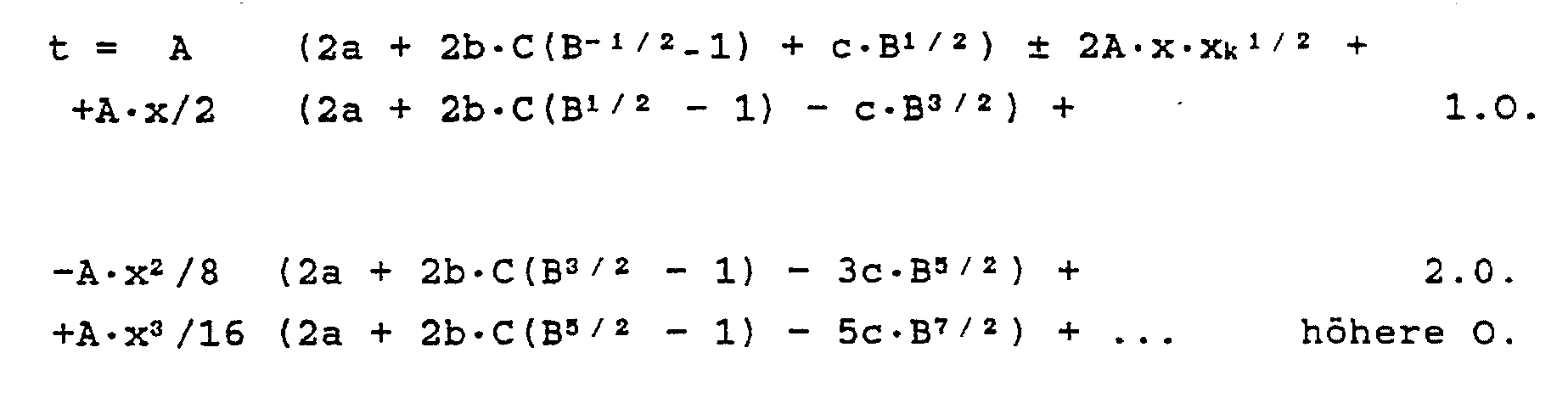
(I.) a = {c·[(c - 2b)/3c]3/2 + b} · (c - 2b)/(c + 2b)
(II.) Ub/(Ua + Ub) = (2c + 2b)/3cThe blur x = x₀ + x k includes both the blur x₀ due to location blur in the formation of ions, as well as the initial kinetic energy of the ions. The latter term (x k ) contributes not only to an energy blur but also to a time blur ("turn-around-time"), which must be taken into account separately. A development after x finally results
(I.) a = {c · [(c - 2b) / 3c] 3/2 + b} · (c - 2b) / (c + 2b)
(II.) U b / (U a + U b ) = (2c + 2b) / 3c
Während bei einer einstufigen Ionenquelle der Abstand Ionenentstehungsort-Ortsfokus festgelegt ist (in Fig. 1 entspräche dies b=O, c=2a), kann er bei einer zweistufigen Ionenquelle in sehr weiten Grenzen verändert werden. Sehr vorteilhaft ist es, den Ortsfokus 30 so weit wie möglich von der Ionenquelle A weg zu schieben, beziehungsweise die Strecke c so groß wie möglich zu machen. Eine möglichst lange Flugstrecke c (z.B. 10 bis 20 cm) führt bereits zu deutlichen Flugzeitenunterschieden der einzelnen Massen. In Verbindung mit einer Ortsfokussierung zweiter Ordnung läßt sich somit in einem solchen Ortsfokus 30 bereits eine Massenauflösung von 500 bis 1000 erreichen.While the distance between the ion source and the location focus is fixed for a single-stage ion source (this corresponds to b = O, c = 2a in FIG. 1), it can be changed within very wide limits for a two-stage ion source. It is very advantageous to push the
Für a=1,5 cm, b=1 cm, c=10 cm, kinetische Energie der Ionen 400 eV, Ionenmasse 100 amu, ergibt sich eine Flugzeit tg e s von ca. 5 µsec. Mit einer Pulsbreite des anregenden Strahles 5 von Dt=5nsec ergibt sich für Auflösung der Wert R=1/2.t/Dt = 500, mit Dt=2nsec der Wert R=1250. Die Energiekorrektur 2. Ordnung führt auch im letzteren Fall noch zu Ionenpulsbreiten kleiner Dt und begrenzt damit die Auflösung nicht.For a = 1.5 cm, b = 1 cm, c = 10 cm, the kinetic energy of the ions 400 eV, ion mass 100 amu, results in a flight time t ges microseconds of approx. 5 With a pulse width of the
Bei allen Ausführungsformen des erfindungsgemäßen Flugzeit-Massenspektrometers wird durch geeignete Wahl der Blendenabstände in der Ionenquelle A und durch Anlegen geeigneter Potentiale U₁, Ub und U₀ an die Blenden 1, 2, 3 ein solcher Ortsfokus 2. Ordnung erzeugt. Zur exakten Justierung des Ortsfokus 30 auf einen definierten Abstand c, die durch Variation des Abstandes a des Entstehungsortes der Ionen von der zweiten Blende 2 und der Spannungen an den Blenden 1 und 2 erreicht werden kann, dient ein geeigneter Ionendetektor 11 mit ebener Auftreffläche; dieser Detektor kann mittels einer mechanische Verschiebevorrichtung in die Ionenflugbahn des primären Ionenstrahles 25 gebracht und für MS-MS-Messungen wieder daraus entfernt werden.In all embodiments of the time-of-flight mass spectrometer according to the invention, such a location focus of the 2nd order is generated by a suitable choice of the aperture distances in the ion source A and by applying suitable potentials U₁, U b and U₀ to the apertures 1, 2, 3. A
Zur automatischen Nachführung des Potentials Ub gemäß Gleichung (II.) bei gegebenem Potential U₁ und gegebenen Abständen a, b, c ist eine nicht dargestellte elektronische Steuerungseinrichtung vorgesehen.An electronic control device (not shown) is provided for automatically tracking the potential U b according to equation (II.) At a given potential U 1 and given distances a, b, c.
Der in Fig. 1 gezeigte Ionenreflektor C besteht aus einer zweistufigen Anordnung, nämlich den ein Bremsfeld definierenden Bremselektroden 6 und 7 und der Reflektorendplatte 8, die zusammen mit der in Richtung des einfallenden Ionenstrahles gesehen zweiten Bremselektrode 7 ein Reflektorfeld definiert. Bei der hier dargestellten Ausführungsform sind die Bremselektroden 6, 7 als Lochblenden ausgebildet. Die Reflektorendplatte 8 ist so angebracht, daß sie in den Reflektor hinein oder aus ihm herausgeschoben werden kann. Dabei wird die Spannung an dieser Endplatte so nachgeführt, daß die Feldstärke zwischen Bremselektrode 7 und Reflektorendplatte 8 nicht verändert wird. Die Bremselektroden 6 und 7 besitzen eine mehrere Zentimeter große Öffnung, die entweder mit einem Netz zur Erzeugung paralleler Aquipotentialflächen versehen ist; oder sie werden ohne Netze betrieben, dann aber mit einer Vorblende 9, die auf der Apparatemasse des Flugzeit-Massenspektrometers liegt. Die für solche Reflektoren benötigten Spannungen entsprechen den aus der Literatur bekannten Werten. Die Symmetrieachse 40 des Ionenreflektors C kann sowohl, wie in Fig. 1 dargestellt, einen Winkel zur Ionenflugrichtung haben, als auch kollinear mit ihr verlaufen. Im letzteren Fall wird jedoch ein spezieller Ionendetektor benötigt (siehe unten). The ion reflector C shown in FIG. 1 consists of a two-stage arrangement, namely the
Die feldfreie Ionendriftstrecke D wird einfach durch ein genügend langes, leeres Vakuumrohr zwischen einer sekundären Wechselwirkungszone B und dem Ionenreflektor C gebildet, entsprechend bekannten Anordnungen. Nur ein geeigneter Ionendetektor 10 (z.B. Vielkanalplattendetektor) befindet sich am Ende der Ionenflugbahnen, möglichst nahe bei der sekundären Wechselwirkungszone B. Im Falle eines in sich zurückreflektierenden Ionenreflektros C befindet sich der Ionendetektor 10 auf der einfallenden Ionenflugrichtung mit einer konzentrischen Öffnung in der Mitte für den Durchtritt der von der Ionenquelle A und der sekundären Wechselwirkungszone B kommenden Ionen. The field-free ion drift distance D is simply formed by a sufficiently long, empty vacuum tube between a secondary interaction zone B and the ion reflector C, in accordance with known arrangements. Only a suitable ion detector 10 (e.g. multichannel plate detector) is located at the end of the ion trajectory, as close as possible to the secondary interaction zone B. In the case of a self-reflecting ion reflector C, the
Die sekundäre Wechselwirkungszone B enthält den Ortsfokus 30 und ist das Herzstück des MS-MS-Flugzeit-Massenspektrometers. Bei der in Fig. 2a gezeigten Ausführungsform wird der Fokus 12 eines zweiten Laserpulses mit ausgewählter Wellenlänge und Intensität genau in den Ortsfokus 30 plaziert. Wahlweise kann dieser Laserpuls durch andere gepulste, örtlich scharfe Zugriffsmethoden (z.B. Elektronenstrahl) ersetzt werden. Variiert man die zeitliche Verzögerung zwischen der primären Ionenerzeugung in der Ionenquelle A und dem sekundären Zugriff im Ortsfokus 30, so werden der Reihe nach die einzelnen, verschieden schweren Ionen entsprechend ihrer verschiedenen Flugzeiten tg e s selektiv angeregt und können somit auch selektiv durch Photodissoziation fragmentieren. Ist die Pulslänge nur kurz genug und der Fokus 12 nur klein genug (z.B. 0,1 mm), so kann die im Ortsfokus 30 mögliche, maximale Massenauflösung erhalten werden. Der sekundäre Zugriff ist somit sowohl für die sekundäre Massenselektion, wie auch für die sekundäre Fragmentierung verantwortlich. The secondary interaction zone B contains the
Ist der Ionenreflektor C optimal auf die kinetische Energie der primären Ionen im Ionenstrahl 25 korrigiert und der zweite Laser nicht eingeschaltet, so erhält man ein übliches primäres Massenspektrum. Um ein sekundäres Massenspektrum der mit dem sekundären Zugriff ausgewählten Ionen zu erhalten, muß nun die Spannung am Ionenreflektor C kontinuierlich erniedrigt werden, wobei das Verhältnis der Spannungen an den Bremselektroden 6, 7 und der Reflektorendplatte 8 (sowie evtl. der Vorblende 9) erhalten bleibt. Der gesamte Ionenreflektor C ist damit für abnehmende Ionenenergien optimal korrigiert. Bei einer Fragmentierung im feldfreien Raum wird die kinetische Energie eines Molekülions im Verhältnis zu den Massen der Fragmente auf diese verteilt; sekundäre Fragmente mit kleinerer Masse haben somit auch kleinere kinetische Energien. Man stimmt damit also die Energiekorrektur des Ionenspiegels über abnehmende Massen der sekundären Fragmentionen ab. Dies bedeutet aber, daß nacheinander sekundäre Fragmentionen mit abnehmender Masse innerhalb eines festen Zeitfensters am Ionendetektor 10 ankommen. Registriert man nur innerhalb dieses Zeitfensters Signale des Ionendetektors 10, so erhält man ein sekundäres Massenspektrum und zwar mit linearer Massenskala. Alle primären Molekül- und Fragmentionen haben eine maximale kinetische Energie, dringen somit am weitesten in den Ionenreflektor C ein und können durch Anstoßenlassen an der Reflektorendplatte 8 des Ionenreflektors C aus dem Massenspektrum eliminiert werden. Mit anderen Worten, der Ionenreflektor C mit verschiebbarer Reflektorendplatte 8 und Zeitfenster arbeitet als abstimmbarer Energieanalysator und somit, nach dem oben über die Fragmentenergien gesagten, als Analysator für die Massen der sekundären Fragmentionen.If the ion reflector C is optimally corrected for the kinetic energy of the primary ions in the
In den Fig. 3b-d sind solche sekundären Massenspektren dargestellt, wobei als Ordinate jeweils die am Ionendetektor 10 gemessene Intensität der einfallenden Ionen und als Abszisse die in Ionenmassen m geeichte Spannung der Reflektorendplatte 8 aufgetragen ist. Fig. 3a zeigt ein primäres Laser-Flugzeitspektrum von Benzol, bei dem die Intensität des ersten Lasers so gewählt wurde, daß neben der Ionisation zusätzlich eine teilweise Fragmentierung der Benzolionen stattfand. In Fig. 3b wurden durch geeignete Verzögerung des zweiten Lasers nur die Molekülionen im Ortsfokus erfaßt, angeregt und fragmentiert; das sekundäre Massenspektrum ist hier zu sehen. In Fig. 3c wurden im Ortsfokus 30 nur die Fragmentionen C₄H₄ ⁺ selektiv fragmentiert, in Fig. 3d nur die Fragmentionen C₄H₂ ⁺. Die sekundären Massenspektren dieser beiden Fragmentionen unterscheiden sich gravierend, was auf verschiedene Zerfallswege in Übereinstimmung mit theoretischen Überlegungen zurückzuführen ist. In diesen vorläufigen Spektren wurde bereits eine Auflösung der sekundären Massenspektren von R=600 erreicht, obwohl diese hier durch nicht optimale Reflektorkorrektur und durch zu große Schritte bei der Variation der Spannungen am Ionenreflektor C begrenzt war.3b-d show such secondary mass spectra, the ordinate being the intensity of the incident ions measured on the
Um optimale Korrektur des Ionenreflektor C mit einer Eliminierung der primären Ionen erreichen zu können, ist die bewegliche Reflektorendplatte 8 vorgesehen. Damit können die Spannungen am Ionenreflektor C auf optimale Energiekorrektur eingestellt werden; dann wird die Reflektorendplatte 8 soweit in das Reflektorfeld hineingeschoben, daß der Umkehrpunkt der primären Ionen genau auf ihr liegt. Um das Reflektorfeld und damit die Energiekorrektur unbeeinflußt zu lassen muß die Reflektorendplatte 8 immer auf einer Spannung liegen, die der Äquipotentialfläche ihrer jeweiligen Position genau entspricht; dies kann in Ausführungsformen durch einen nicht dargestellten Schleifkontakt oder eine elektronische Spannungsnachführung geschehen.In order to be able to achieve optimum correction of the ion reflector C with an elimination of the primary ions, the movable reflector end plate 8 is provided. The voltages at the ion reflector C can thus be set to optimal energy correction; then the reflector end plate 8 is pushed so far into the reflector field that the point of reversal of the primary ions lies exactly on it. In order to leave the reflector field and thus the energy correction unaffected, the reflector end plate 8 must always be at a voltage which corresponds exactly to the equipotential surface of its respective position; In embodiments, this can be done by means of a sliding contact (not shown) or electronic voltage tracking.
Damit läßt sich auch für sekundäre Massenspektren eine Auflösung von 5000 und darüber erreichen, ähnlich der primärer Massenspektren.This means that a resolution of 5000 and above can also be achieved for secondary mass spectra, similar to the primary mass spectra.
Bei der Fig. 2b-d gezeigten Ausführungsform besteht der sekundäre Eingriff in einem besonderen Maschennetz 23, das sich wiederum genau im Ortsfokus 30 befindet. Dieses Maschennetz 23 besteht aus zwei kammartigen Strukturen 13 und 14, deren "Zähne" mittig ineinandergreifen ohne sich zu berühren. Die "Zähne" bestehen aus möglichst feinen Drähten; alle zu einem Kamm gehörenden "Zähne" sind elektrisch miteinander verbunden; ihre Abstände sind 0,3 mm und kleiner, beziehungswiese 0,15 mm oder kleiner zu den "Zähnen" des anderen Kammes. An die beiden Kämme werden am günstigsten komplementäre Spannungspulse ± U angelegt (gleiche Amplitude, gleiche Länge, entgegengesetztes Vorzeichen), so daß einerseits Ionen, die im richtigen Zeitpunkt zwischen den Zähnen hindurchfliegen, ein transversales elektrisches Feld spüren und seitlich abgelenkt werden, so daß aber andererseits in sehr geringem Abstand vom Maschennetz 23 die gepulsten Felder sich bereits wieder aufheben.In the embodiment shown in FIGS. 2b-d, the secondary intervention consists in a
Spannungspulse vom 5 nsec Länge und einigen 100 V reichen bereits aus, um die entsprechenden Ionen soweit abzulenken, daß sie nicht mehr den Ionendektor 10 treffen und damit aus dem Massenspektrum eliminiert werden (Fig. 2c). Werden andererseits durch einen Spannungspuls die beiden, auf verschiedenem Potential +U und -U liegenden "Kämme" kurzzeitig auf dasselbe Potential gebracht (Fig. 2d), dann werden nur die Ionen, die genau zum Zeitpunkt des Pulses das Maschennetz 23 durchfliegen, nicht abgelenkt und erscheinen als einzige im Massenspektrum. Damit können einerseits bei Analysen von Gemischen (z.B. wegen zu hoher Intensitäten) unerwünschte Ionen eliminiert werden, aber andererseits auch gezielt Ionen für weitere, sekundäre Fragmentierung selektiert werden. In Fig. 4a und b sind erste Ergebnisse mit einem Prototyp des Maschennetzes 23 (Abstand benachbarter "Zähne" 1 mm, bzw. 0,5 mm, Pulslänge 10 nsec, Pulshöhe 100 V) an OCS⁺ und seinen ¹³C, ³³S und ³⁴S Isotopen zu sehen. Die mit 93,5 % bei weitem häufigste Masse 60 (Fig. 4a) wurde bis auf einen Rest von 6 % eliminiert (Fig. 4b). Für die Experimente, bei denen diese Messung durchgeführt wurde, war eine völlige Unterdrückung der Masse 60 unerwünscht, so daß diese Abbildung nur als Demonstration des Effekts zu betrachten ist.Voltage pulses of 5 nsec in length and a few 100 V are already sufficient to deflect the corresponding ions to such an extent that they no longer hit the
Die in Fig. 2e gezeigte Ausführungsform stellt in gewisser Weise eine Kombination der Ausführungsformen aus Fig. 2a und 2b dar. In der Ausführungsform von Fig. 2a kann ein sekundäres Massenspektrum nur sequentiell und nicht mit einem einzigen Laserpuls erhalten werden. In der in Fig. 2e gezeigten Ausführungsform wird die Tatsache ausgenutzt, daß ein zweistufiger Ionenreflektor 20 % Energieunschärfe noch so korrigieren kann, daß eine Massenauflösung von 5000 ohne weiteres erreicht wird. Um den Verlust kinetischer Energie, der bei der Ionenfragmentierung auftritt, noch in diesem Rahmen zu halten, werden die Fragmentionen nach dem Ortskokus 30 nachbeschleunigt. Die kinetische Energie der Ionen am Ortsfokus 30 darf dabei nur einen Bruchteil der endgültigen kinetischen Ionenenergie betragen. Dazu wird die Ionenquelle A mit den Blenden 1, 2 und 3, das Maschennetz 23 im Ortsfokus 30 und eine zusätzliche, abschließende vierte Blende 15 auf ein erhöhtes Potential U₀ gelegt. Zwischen der vierten Blende 15 und einer auf Massepotential liegenden fünften Blende 16 findet dann die Nachbeschleunigung statt. Zwischen den Blenden 3 und 15 befindet sich ein feldfreier Driftraum mit dem Ortsfokus 30, abgeschirmt durch ein Rohr 17, das auf demselben Potential liegt, wie die Blenden 3 und 15 und dem Bezugspotential des Maschennetzes 23 entspricht.The embodiment shown in FIG. 2e represents to some extent a combination of the embodiments from FIGS. 2a and 2b. In the embodiment of FIG. 2a, a secondary mass spectrum can only be obtained sequentially and not with a single laser pulse. In the embodiment shown in FIG. 2e, the fact is used that a two-stage ion reflector can still correct 20% energy blur, that a mass resolution of 5000 is easily achieved. In order to keep the loss of kinetic energy that occurs during ion fragmentation within this framework, the fragment ions are accelerated after the
Entstehen zum Beispiel Ionen auf dem Potential 2000 V, und liegt Blende 3 und 15 auf 1600 V (kinetische Energie im Ortsfokus 400 eV), dann ist bereits die obige Bedingung für gute Massenauflösung gegeben. Das Maschennetz 23 ist wie bei der in Fig. 2b gezeigten Ausführungsform im Ortsfokus 30 angebracht; damit werden mit hoher Massenauflösung ausgesuchte primäre Ionen selektiert. Kurz dahinter (z.B. 1 mm) wird der Fokus 18 eines zweiten Lasers oder eines anderen gepulsten Zugriffs, z.B. Elektronenstrahl oder Ionenstrahl, auf den das Maschennetz auf der Symetrieachse 20 verlassenden Ionenstrahl justiert. Sind der Spannungspuls am Maschennetz 23 und der zweite Laserpuls 18 oder bei Ausführungsformen ein andersartiger Zugriffspuls genau mit der Flugzeit der zu untersuchenden primären Ionen definierter Masse synchronisiert, so erhält man ein sekundäres Massenspektrum dieser Ionen.If, for example, ions arise at the potential of 2000 V and f-
Somit kann nun ein komplettes sekundäres Massenspektrum mit einem einzigen Ionisations- und Fragmentierungspuls erhalten werden. Mit Hilfe der verschiebbaren Reflekorendplatte 8 können zusätzlich alle primären Ionen ausgeblendet werden.A complete secondary mass spectrum can now be obtained with a single ionization and fragmentation pulse. With the help of the sliding reflector end plate 8, all primary ions can also be hidden.
Des weiteren kann bei Ausführungsformen auch das Maschennetz 23 durch den Laserfokus 18 (oder andere gepulste Zugriffsmethoden) ersetzt werden; dann aber können metastabile Ionenzerfälle, die vor dem Ortsfokus 30 stattfinden, das sekundäre Massenspektrum des ausgewählten Ions stören. Mit dem Maschennetz 23 kann schließlich der sekundäre Zugriff auch aus einer kontinuierlichen Wechselwirkung bestehen, wie z.B. einem kontinuierlichen Elektronenstrahl, Molekular- oder Atomstrahl oder einer Stoßgaszelle. Letztere muß aber dann vor dem Maschengitter und die Nachbeschleunigung so nahe wie möglich hinter dem Maschengitter angebracht werden.Furthermore, in embodiments, the
Zur Erhöhung der Massenauflösung kann bei Ausführungsformen das sekundäre Massenspektrum auch in zwei oder mehrere Massenbereiche aufgeteilt werden, wobei die Energiekorrektur des Reflektors nur auf einen dieser Bereiche und damit nur auf 10 %, 5 % etc. Energieabweichung optimiert werden muß. Für die Nachbeschleunigung zwischen den Blenden 15 und 16 reichen dann wesentlich geringere Spannungen im Vergleich zur primären Ionenenergie Ua+Ub aus.In order to increase the mass resolution, in embodiments the secondary mass spectrum can also be divided into two or more mass ranges, the energy correction of the reflector only having to be optimized on one of these ranges and thus only on 10%, 5% etc. energy deviation. For the post-acceleration between the
Auch das Messen reiner "Metastabilen-Massenspektren" ist möglich. Unter einem "Metastabilen-Massenspektrum" sei hier das Massenspektrum aller Produktionen aus dem metastabilen Zerfall eines ausgesuchten Vorläuferions, das in der Ionenquelle entstanden ist, gemeint. Dieser metastabile Zerfall wird meist durch die zusätzliche Anregung der primären Ionen am Ort der Ionisation, z.B. durch Weiterabsorption eines Photons von Laser 1 im Primärion, induziert. Eine Anregung z.B. durch Laser 2 ist dann nicht nötig. Zum Aufnehmen von "Metastabilen-Massenspektren" wird also nur Laser 2 ausgeschaltet. Ansonsten werden entweder die Ionenreflektor-Potentiale abgestimmt oder eine Nachbeschleunigung verwendet (gesamtes "Metastabilen-Massenspektrum" mit wenigen oder sogar einem Laserschuß); dies ist ganz analog zur Aufnahme von sekundären Massenspektren. Im Falle der Nachbeschleunigung werden aber nur Produktionen aus Zerfällen, die vor der Nachbeschleunigung stattfanden, nachgewiesen. Durch Verlängerung der feldfreien Strecke zwischen Ionenquelle und Nachbeschleunigung kann dieser Bereich vergrößert werden. Auch für "Metastabilen-Massenspektren" werden wieder primäre Ionen durch Anstoßen an der Ionenreflektor-Endplatte eliminert werden. Die Maschengitter-Ablenkung im oder nahe beim Ortsfokus kann zur weiteren Unterdrückung störender Ionen, z.B. Produktionen aus metastabilen Zerfällen anderer Primärionen, eingesetzt werden.It is also possible to measure pure "metastable mass spectra". A “metastable mass spectrum” here means the mass spectrum of all productions from the metastable decay of a selected precursor ion that has arisen in the ion source. This metastable decay is usually induced by the additional excitation of the primary ions at the ionization site, for example by further absorption of a photon by laser 1 in the primary ion. A suggestion, e.g. by laser 2 is then not necessary. In order to record "metastable mass spectra", only laser 2 is switched off. Otherwise, either the ion reflector potentials are tuned or post-acceleration is used (entire "metastable mass spectrum" with few or even one laser shot); this is quite analogous to the acquisition of secondary mass spectra. In the case of post-acceleration, however, only productions from decays that took place before post-acceleration are detected. This area can be enlarged by extending the field-free distance between the ion source and post-acceleration. For "metastable mass spectra" too, primary ions will be eliminated again by bumping against the ion reflector end plate. The mesh lattice deflection in or near the location focus can be used to further suppress interfering ions, for example productions from metastable decays of other primary ions.
Claims (14)
dadurch gekennzeichnet,
daß die Ionenquelle (A) derart gestaltet ist, daß an einem Ortsfokus (30) von 2. Ordnung alle Ionen der gleichen Masse, die zur selben Zeit, aber an verschiedenen Stellen in der Ionenquelle (A) erzeugt werden und daher verschiedene kinetische Energien besitzen, gleichzeitig eintreffen, daß am Ortsfokus (30) eine Einrichtung vorgesehen ist, mit der der physikalische Zustand der Ionen pulsweise mindestens einer der folgenden Änderungen unterworfen werden kann, nämlich Änderung des Impulses, Änderung des quantenmechanischen Zustands der Elektronenhülle, chemische Reaktion oder Fragmentation, wodurch jeweils aus dem primären Ionenstrahl (25) ein sekundärer Ionenstrahl mit neuen physikalischen Eigenschaften erzeugt wird, und daß der Ionenreflektor (C) derart gestaltet ist, daß er bei entsprechender Betriebsart eine Zeitfokussierung sekundärer Ionen gleicher Masse und eine Ausblendung der Primärionen bewirkt.1. time-of-flight mass spectrometer with an ion source (A) for generating a pulsed primary ion beam (25), with a device (B) for pulsed, locally delimited influencing of the ions and with an ion reflector (C) for compensating for time-of-flight differences of the ions, same mass,
characterized,
that the ion source (A) is designed in such a way that all ions of the same mass, which are generated at the same time but at different locations in the ion source (A) and therefore have different kinetic energies, at a location focus (30) of the second order , arrive at the same time that a device is provided at the location focus (30) with which the physical state of the ions can be subjected to at least one of the following changes in pulses, namely change in the momentum, change in the quantum mechanical state of the electron shell, chemical reaction or fragmentation, thereby in each case a secondary ion beam with new physical properties is generated from the primary ion beam (25), and that the ion reflector (C) is designed in such a way that, with the corresponding operating mode, it effects time focusing of secondary ions of the same mass and the primary ions are masked out.
wobei die Ionen zwischen der ersten, Ionen-abstoßenden (1) und der zweiten, Ionen-anziehenden (2) Blende in einem Abstand a von der zweiten Blende (2) erzeugt werden, der kleiner ist als der Abstand der ersten (1) von der zweiten Blende (2),
dadurch gekennzeichnet, daß
der Abstand a zwischen dem Entstehungsort der Ionen und der zweiten Blende (2), der Abstand b zwischen der zweiten (2) und der dritten, Ionen-nachbeschleunigenden Blende (3), der Abstand c zwischen der dritten Blende (3) und einem Ortsfokus (30) genannten, auf der Flugbahn der Ionen in Flugrichtung nach der dritten Blende (3) gelegenen Raumpunkt sowie das Verhältnis der Potentialdifferenz Ub zwischen der dritten (3) und der zweiten Blende (2) zur Potentialdifferenz Ua + Ub zwischen der dritten Blende und dem Entstehungsort der Ionen so gewählt sind, daß die Beziehungen
a = {c· [(c - 2b)/3c]3/2 + b} · (c - 2b)/2(c + 2b)
und Ub/(Ua + Ub) = (2c + 2b)/3c
erfüllt sind.2. Time-of-flight mass spectrometer, in particular according to claim 1, whose ion source (A) has at least 3 diaphragms (1, 2, 3) with a common axis of symmetry (20), on which pulsed current or constant electrical potentials are present,
wherein the ions between the first, ion-repellent (1) and the second, ion-attracting (2) aperture are generated at a distance a from the second aperture (2) that is smaller than the distance from the first (1) from the second aperture (2),
characterized in that
the distance a between the origin of the ions and the second aperture (2), the distance b between the second (2) and the third ion-accelerating aperture (3), the distance c between the third aperture (3) and a location focus (30), on the trajectory of the ions in the direction of flight after the third aperture (3), and the ratio of the potential difference U b between the third (3) and the second aperture (2) to the potential difference U a + U b between the third aperture and the origin of the ions are chosen so that the relationships
a = {c · [(c - 2b) / 3c] 3/2 + b} · (c - 2b) / 2 (c + 2b)
and U b / (U a + U b ) = (2c + 2b) / 3c
are fulfilled.
dadurch gekennzeichnet, daß
eine Einrichtung zur Beeinflussung der Ionen am Ortsfokus (30) durch Pulse, die modulo einer definierten Zeitverzögerung mit der Erzeugung der Ionenpulse in der Ionenquelle (A) synchronisiert sind, vorgesehen ist.6. Time-of-flight mass spectrometer according to one of the preceding claims,
characterized in that
A device is provided for influencing the ions at the location focus (30) by pulses which are synchronized modulo of a defined time delay with the generation of the ion pulses in the ion source (A).
dadurch gekennzeichnet, daß
die Reflektorendplatte (8) längs der Symmetrieachse (40) des Ionenreflektors (C) verschiebbar angeordnet ist und daß bei Verschiebung der Reflektorendplatte (8) das an ihr anliegende elektrische Potential so nachgeführt wird, daß die elektrische Feldstärke zwischen der Reflektorendplatte (8) und der ihr zunächst liegenden Bremselektrode (7) nicht verändert wird.12. Time-of-flight mass spectrometer with an ion reflector (C), in particular according to one of the preceding claims, the ion reflector (C) of which has a reflector end plate (8) and a plurality of brake electrodes (6, 6) arranged at a distance in front of it on a common axis of symmetry (40) and defining a brake field. 7) contains
characterized in that
the reflector end plate (8) is displaceably arranged along the axis of symmetry (40) of the ion reflector (C) and that when the reflector end plate (8) is displaced, the electrical potential applied to it is adjusted so that the electric field strength between the reflector end plate (8) and the your initially lying brake electrode (7) is not changed.
Applications Claiming Priority (2)
| Application Number | Priority Date | Filing Date | Title |
|---|---|---|---|
| DE3920566A DE3920566A1 (en) | 1989-06-23 | 1989-06-23 | MS-MS FLIGHT TIME MASS SPECTROMETER |
| DE3920566 | 1989-06-23 |
Publications (3)
| Publication Number | Publication Date |
|---|---|
| EP0403965A2 true EP0403965A2 (en) | 1990-12-27 |
| EP0403965A3 EP0403965A3 (en) | 1991-07-31 |
| EP0403965B1 EP0403965B1 (en) | 1994-10-26 |
Family
ID=6383404
Family Applications (1)
| Application Number | Title | Priority Date | Filing Date |
|---|---|---|---|
| EP90111293A Expired - Lifetime EP0403965B1 (en) | 1989-06-23 | 1990-06-15 | MS-MS-flight time mass spectrometer |
Country Status (3)
| Country | Link |
|---|---|
| US (1) | US5032722A (en) |
| EP (1) | EP0403965B1 (en) |
| DE (2) | DE3920566A1 (en) |
Cited By (8)
| Publication number | Priority date | Publication date | Assignee | Title |
|---|---|---|---|---|
| EP0456517A2 (en) * | 1990-05-11 | 1991-11-13 | Kratos Analytical Limited | Time-of-flight mass spectrometer |
| EP0587707A1 (en) * | 1991-04-25 | 1994-03-23 | Applied Biosystems, Inc. | Time-of-flight mass spectrometer with an aperture enabling tradeoff of transmission efficiency and resolution |
| WO1995033279A1 (en) * | 1994-05-31 | 1995-12-07 | University Of Warwick | Tandem mass spectrometry apparatus |
| GB2303962A (en) * | 1994-05-31 | 1997-03-05 | Univ Warwick | Tandem mass spectrometry apparatus |
| DE19544808A1 (en) * | 1995-12-01 | 1997-06-05 | Bruker Franzen Analytik Gmbh | Methods and devices for mass spectrometry of daughter ions |
| US5654545A (en) * | 1995-09-19 | 1997-08-05 | Bruker-Franzen Analytik Gmbh | Mass resolution in time-of-flight mass spectrometers with reflectors |
| DE19631161A1 (en) * | 1996-08-01 | 1998-02-12 | Bergmann Thorald | Time of flight time of flight mass spectrometer with differentially pumped collision cell |
| DE19631162A1 (en) * | 1996-08-01 | 1998-02-12 | Bergmann Thorald | Collision cell with integrated ion selector for time-of-flight time-of-flight mass spectrometers |
Families Citing this family (45)
| Publication number | Priority date | Publication date | Assignee | Title |
|---|---|---|---|---|
| GB2250632B (en) * | 1990-10-18 | 1994-11-23 | Unisearch Ltd | Tandem mass spectrometry systems based on time-of-flight analyser |
| DE4106796A1 (en) * | 1991-03-04 | 1991-11-07 | Wollnik Hermann | A FLIGHT-TIME MASS SPECTROMETER AS SECOND LEVEL OF AN MS-MS SYSTEM |
| DE4108462C2 (en) * | 1991-03-13 | 1994-10-13 | Bruker Franzen Analytik Gmbh | Method and device for generating ions from thermally unstable, non-volatile large molecules |
| US6111645A (en) | 1991-04-29 | 2000-08-29 | Massachusetts Institute Of Technology | Grating based phase control optical delay line |
| US6485413B1 (en) | 1991-04-29 | 2002-11-26 | The General Hospital Corporation | Methods and apparatus for forward-directed optical scanning instruments |
| US5202563A (en) * | 1991-05-16 | 1993-04-13 | The Johns Hopkins University | Tandem time-of-flight mass spectrometer |
| US5144127A (en) * | 1991-08-02 | 1992-09-01 | Williams Evan R | Surface induced dissociation with reflectron time-of-flight mass spectrometry |
| US5160840A (en) * | 1991-10-25 | 1992-11-03 | Vestal Marvin L | Time-of-flight analyzer and method |
| US5614711A (en) * | 1995-05-04 | 1997-03-25 | Indiana University Foundation | Time-of-flight mass spectrometer |
| US6002127A (en) | 1995-05-19 | 1999-12-14 | Perseptive Biosystems, Inc. | Time-of-flight mass spectrometry analysis of biomolecules |
| US5625184A (en) * | 1995-05-19 | 1997-04-29 | Perseptive Biosystems, Inc. | Time-of-flight mass spectrometry analysis of biomolecules |
| US5986258A (en) * | 1995-10-25 | 1999-11-16 | Bruker Daltonics, Inc. | Extended Bradbury-Nielson gate |
| US5712480A (en) * | 1995-11-16 | 1998-01-27 | Leco Corporation | Time-of-flight data acquisition system |
| US5742049A (en) * | 1995-12-21 | 1998-04-21 | Bruker-Franzen Analytik Gmbh | Method of improving mass resolution in time-of-flight mass spectrometry |
| US5641959A (en) * | 1995-12-21 | 1997-06-24 | Bruker-Franzen Analytik Gmbh | Method for improved mass resolution with a TOF-LD source |
| WO1998000224A1 (en) * | 1996-07-03 | 1998-01-08 | Analytica Of Branford, Inc. | A time-of-flight mass spectrometer with first and second order longitudinal focusing |
| US5814813A (en) * | 1996-07-08 | 1998-09-29 | The Johns Hopkins University | End cap reflection for a time-of-flight mass spectrometer and method of using the same |
| JP2942815B2 (en) * | 1996-11-05 | 1999-08-30 | 工業技術院長 | Particle selection method and time-of-flight type selection type particle analyzer |
| US6259101B1 (en) * | 1997-09-23 | 2001-07-10 | University Of Delaware | Method and instruments for the on-line detection, sizing or analysis of aerosol particles |
| USRE39099E1 (en) * | 1998-01-23 | 2006-05-23 | University Of Manitoba | Spectrometer provided with pulsed ion source and transmission device to damp ion motion and method of use |
| US6331702B1 (en) * | 1999-01-25 | 2001-12-18 | University Of Manitoba | Spectrometer provided with pulsed ion source and transmission device to damp ion motion and method of use |
| US6348688B1 (en) | 1998-02-06 | 2002-02-19 | Perseptive Biosystems | Tandem time-of-flight mass spectrometer with delayed extraction and method for use |
| US5969350A (en) * | 1998-03-17 | 1999-10-19 | Comstock, Inc. | Maldi/LDI time-of-flight mass spectrometer |
| US6184523B1 (en) * | 1998-07-14 | 2001-02-06 | Board Of Regents Of The University Of Nebraska | High resolution charged particle-energy detecting, multiple sequential stage, compact, small diameter, retractable cylindrical mirror analyzer system, and method of use |
| WO2000017909A1 (en) | 1998-09-23 | 2000-03-30 | Varian Australia Pty Ltd | Ion optical system for a mass spectrometer |
| DE69942124D1 (en) * | 1998-09-25 | 2010-04-22 | Oregon State | TANDEM-flight mass spectrometer |
| CA2255122C (en) * | 1998-12-04 | 2007-10-09 | Mds Inc. | Improvements in ms/ms methods for a quadrupole/time of flight tandem mass spectrometer |
| US6507019B2 (en) | 1999-05-21 | 2003-01-14 | Mds Inc. | MS/MS scan methods for a quadrupole/time of flight tandem mass spectrometer |
| US6445939B1 (en) | 1999-08-09 | 2002-09-03 | Lightlab Imaging, Llc | Ultra-small optical probes, imaging optics, and methods for using same |
| US6570153B1 (en) | 2000-10-18 | 2003-05-27 | Agilent Technologies, Inc. | Tandem mass spectrometry using a single quadrupole mass analyzer |
| DK1217643T3 (en) * | 2000-12-15 | 2009-01-19 | V & F Analyse & Messtechnik | Method and apparatus for assessing the state of organisms and natural products and for analyzing a gaseous mixture with major and secondary components |
| US7372021B2 (en) * | 2002-05-30 | 2008-05-13 | The Johns Hopkins University | Time-of-flight mass spectrometer combining fields non-linear in time and space |
| WO2003103008A1 (en) * | 2002-05-30 | 2003-12-11 | The Johns Hopkins University | Time of flight mass specrometer combining fields non-linear in time and space |
| US7196324B2 (en) * | 2002-07-16 | 2007-03-27 | Leco Corporation | Tandem time of flight mass spectrometer and method of use |
| GB2390935A (en) | 2002-07-16 | 2004-01-21 | Anatoli Nicolai Verentchikov | Time-nested mass analysis using a TOF-TOF tandem mass spectrometer |
| US7067803B2 (en) * | 2002-10-11 | 2006-06-27 | The Board Of Trustees Of The Leland Stanford Junior University | Gating device and driver for modulation of charged particle beams |
| US20060138316A1 (en) * | 2003-01-28 | 2006-06-29 | Robert Seydoux | Time-of-flight mass spectrometer |
| DE202004015862U1 (en) * | 2003-10-14 | 2005-02-24 | Micromass Uk Ltd. | mass spectrometry |
| US7385186B2 (en) * | 2005-05-13 | 2008-06-10 | Applera Corporation | Methods of operating ion optics for mass spectrometry |
| US7405396B2 (en) * | 2005-05-13 | 2008-07-29 | Applera Corporation | Sample handling mechanisms and methods for mass spectrometry |
| US7351959B2 (en) * | 2005-05-13 | 2008-04-01 | Applera Corporation | Mass analyzer systems and methods for their operation |
| US7501621B2 (en) | 2006-07-12 | 2009-03-10 | Leco Corporation | Data acquisition system for a spectrometer using an adaptive threshold |
| US9159539B2 (en) | 2012-03-28 | 2015-10-13 | Ulvac-Phi, Incorporated | Method and apparatus to provide parallel acquisition of mass spectrometry/mass spectrometry data |
| WO2014057777A1 (en) * | 2012-10-10 | 2014-04-17 | 株式会社島津製作所 | Time-of-flight mass spectrometer |
| CN104392881A (en) * | 2014-09-30 | 2015-03-04 | 青岛康和食品有限公司 | Ion source |
Citations (4)
| Publication number | Priority date | Publication date | Assignee | Title |
|---|---|---|---|---|
| US2938116A (en) * | 1956-04-02 | 1960-05-24 | Vard Products Inc | Molecular mass spectrometer |
| DE3144604A1 (en) * | 1981-11-10 | 1983-05-19 | Leybold-Heraeus GmbH, 5000 Köln | Apparatus for examining a sample |
| FR2548448A1 (en) * | 1983-06-28 | 1985-01-04 | Inst Nat Sciences Appliq | Electrostatic mirror for time-of-flight focusing of charged particles and its application to mass spectrometry |
| JPS6182652A (en) * | 1984-09-29 | 1986-04-26 | Shimadzu Corp | Time-of-flight type collision dissociation mass spectrometer |
Family Cites Families (8)
| Publication number | Priority date | Publication date | Assignee | Title |
|---|---|---|---|---|
| GB1302193A (en) * | 1969-04-18 | 1973-01-04 | ||
| US4072862A (en) * | 1975-07-22 | 1978-02-07 | Mamyrin Boris Alexandrovich | Time-of-flight mass spectrometer |
| US4458149A (en) * | 1981-07-14 | 1984-07-03 | Patrick Luis Muga | Time-of-flight mass spectrometer |
| US4733073A (en) * | 1983-12-23 | 1988-03-22 | Sri International | Method and apparatus for surface diagnostics |
| FR2560434B1 (en) * | 1984-02-29 | 1987-09-11 | Centre Nat Rech Scient | TIME OF FLIGHT MASS SPECTROMETER |
| DE3524536A1 (en) * | 1985-07-10 | 1987-01-22 | Bruker Analytische Messtechnik | FLIGHT TIME MASS SPECTROMETER WITH AN ION REFLECTOR |
| US4818862A (en) * | 1987-10-21 | 1989-04-04 | Iowa State University Research Foundation, Inc. | Characterization of compounds by time-of-flight measurement utilizing random fast ions |
| JPH03503815A (en) * | 1987-12-24 | 1991-08-22 | ユニサーチ リミテッド | mass spectrometer |
-
1989
- 1989-06-23 DE DE3920566A patent/DE3920566A1/en active Granted
-
1990
- 1990-06-15 EP EP90111293A patent/EP0403965B1/en not_active Expired - Lifetime
- 1990-06-15 DE DE59007546T patent/DE59007546D1/en not_active Expired - Lifetime
- 1990-06-20 US US07/541,140 patent/US5032722A/en not_active Expired - Lifetime
Patent Citations (4)
| Publication number | Priority date | Publication date | Assignee | Title |
|---|---|---|---|---|
| US2938116A (en) * | 1956-04-02 | 1960-05-24 | Vard Products Inc | Molecular mass spectrometer |
| DE3144604A1 (en) * | 1981-11-10 | 1983-05-19 | Leybold-Heraeus GmbH, 5000 Köln | Apparatus for examining a sample |
| FR2548448A1 (en) * | 1983-06-28 | 1985-01-04 | Inst Nat Sciences Appliq | Electrostatic mirror for time-of-flight focusing of charged particles and its application to mass spectrometry |
| JPS6182652A (en) * | 1984-09-29 | 1986-04-26 | Shimadzu Corp | Time-of-flight type collision dissociation mass spectrometer |
Non-Patent Citations (4)
| Title |
|---|
| ANALYTICAL INSTRUMENTATION. vol. 16, no. 1, 1987, NEW YORK US Seiten 151 - 171; BOESL U ET AL: "A HIGH-RESOLUTION TIME-OF-FLIGHT MASS SPECTROMETER WITH LASER DESORPTION AND A LASER IONISATION SOURCE" * |
| PATENT ABSTRACTS OF JAPAN vol. 10, no. 255 (E-433)(2311) 02 September 1986, & JP-A-61 82652 (SHIMADZU) 26 April 1986, * |
| REVIEW OF SCIENTIFIC INSTRUMENTS. vol. 26, no. 12, Dezember 1955, NEW YORK US Seiten 1150 - 1157; W C WYLEY ET AL: "TIME-OF-FLIGHT MASS SPECTROMETER WITH IMPROVED RESOLUTION" * |
| SOVIET PHYSICS JETP. vol. 37, no. 1, Juli 1973, NEW YORK US Seiten 45 - 48; B A MAMYRIN ET AL: "THE MASS REFLECTRON, A NEW NONMAGNETIC TIME-OF-FLIGHT MASS SPECTROMETER WITH HIGH RESOLUTION" * |
Cited By (15)
| Publication number | Priority date | Publication date | Assignee | Title |
|---|---|---|---|---|
| EP0456517A3 (en) * | 1990-05-11 | 1992-03-18 | Kratos Analytical Limited | Time-of-flight mass spectrometer |
| EP0456517A2 (en) * | 1990-05-11 | 1991-11-13 | Kratos Analytical Limited | Time-of-flight mass spectrometer |
| EP0587707A1 (en) * | 1991-04-25 | 1994-03-23 | Applied Biosystems, Inc. | Time-of-flight mass spectrometer with an aperture enabling tradeoff of transmission efficiency and resolution |
| EP0587707A4 (en) * | 1991-04-25 | 1995-01-25 | Applied Biosystems | Time-of-flight mass spectrometer with an aperture enabling tradeoff of transmission efficiency and resolution. |
| GB2303962B (en) * | 1994-05-31 | 1998-07-08 | Univ Warwick | Tandem mass spectrometry apparatus |
| WO1995033279A1 (en) * | 1994-05-31 | 1995-12-07 | University Of Warwick | Tandem mass spectrometry apparatus |
| GB2303962A (en) * | 1994-05-31 | 1997-03-05 | Univ Warwick | Tandem mass spectrometry apparatus |
| US5654545A (en) * | 1995-09-19 | 1997-08-05 | Bruker-Franzen Analytik Gmbh | Mass resolution in time-of-flight mass spectrometers with reflectors |
| DE19544808A1 (en) * | 1995-12-01 | 1997-06-05 | Bruker Franzen Analytik Gmbh | Methods and devices for mass spectrometry of daughter ions |
| US5734161A (en) * | 1995-12-01 | 1998-03-31 | Bruker-Franzen Analytik, Gmbh | Method for time-of-flight mass spectrometry of daughter ions |
| DE19544808C2 (en) * | 1995-12-01 | 2000-05-11 | Bruker Daltonik Gmbh | Method for studying the structure of ions in a time-of-flight mass spectrometer |
| DE19631162A1 (en) * | 1996-08-01 | 1998-02-12 | Bergmann Thorald | Collision cell with integrated ion selector for time-of-flight time-of-flight mass spectrometers |
| DE19631161A1 (en) * | 1996-08-01 | 1998-02-12 | Bergmann Thorald | Time of flight time of flight mass spectrometer with differentially pumped collision cell |
| US5854485A (en) * | 1996-08-01 | 1998-12-29 | Bergmann; Thorald Horst | MS/MS time-of-flight mass-spectrometer with collision cell |
| US5854484A (en) * | 1996-08-01 | 1998-12-29 | Bergmann; Thorald Horst | Collision cell with integrated ion selector for MS/MS-time-of flight mass-spectrometer |
Also Published As
| Publication number | Publication date |
|---|---|
| EP0403965B1 (en) | 1994-10-26 |
| DE3920566C2 (en) | 1993-04-01 |
| DE3920566A1 (en) | 1991-01-10 |
| EP0403965A3 (en) | 1991-07-31 |
| US5032722A (en) | 1991-07-16 |
| DE59007546D1 (en) | 1994-12-01 |
Similar Documents
| Publication | Publication Date | Title |
|---|---|---|
| EP0403965B1 (en) | MS-MS-flight time mass spectrometer | |
| DE69631556T2 (en) | Biomolecule analysis by time-of-flight mass spectrometry | |
| DE10005698B4 (en) | Gridless reflector time-of-flight mass spectrometer for orthogonal ion injection | |
| DE112007000922B4 (en) | Mass spectrometry method and mass spectrometer for carrying out the method | |
| DE60128419T2 (en) | Time-of-flight mass spectrometer with selectable drift length | |
| DE19638577C1 (en) | Simultaneous focussing of all masses in time of flight mass spectrometer | |
| DE112007002747B4 (en) | Method for operating a multiple reflection ion trap | |
| DE112008003939B4 (en) | Quasi-planar multiply reflecting time-of-flight mass spectrometer | |
| DE10248814B4 (en) | High resolution time-of-flight mass spectrometer of small design | |
| DE10158924B4 (en) | Pulser for time-of-flight mass spectrometers with orthogonal ion injection | |
| DE60319029T2 (en) | mass spectrometry | |
| DE4442348C2 (en) | Method and device for improved mass resolution of a time-of-flight mass spectrometer with ion reflector | |
| DE4134905A1 (en) | TANDEM MASS SPECTROMETER BASED ON FLIGHT TIME ANALYSIS | |
| DE102013011462B4 (en) | Time-of-Flight Mass Spectrometer with Cassini Reflector | |
| DE2627085A1 (en) | ION SCREENING SPECTROMETER ANALYZERS, PREFERABLY ARRANGED IN TANDEM | |
| DE102011013540A1 (en) | Tandem time-of | |
| DE10162267B4 (en) | Reflector for time-of-flight mass spectrometers with orthogonal ion injection | |
| DE102013015045A1 (en) | Time of flight mass spectrometer and method of controlling the same | |
| DE102007049640B3 (en) | Measurement of daughter ion spectra from a MALDI ionization | |
| DE19635645C2 (en) | Method for the high-resolution spectral recording of analyte ions in a linear time-of-flight mass spectrometer | |
| DE102013015046B4 (en) | Imaging mass spectrometer and method for controlling same | |
| DE2540505A1 (en) | FLIGHT TIME MASS SPECTROMETERS FOR IONS WITH DIFFERENT ENERGIES | |
| DE102007013693A1 (en) | Ion detection system with neutral noise suppression | |
| DE10109917A1 (en) | Measuring laser desorption mass spectra in a time-of-flight mass spectrometer, involves periodically running potential runs for spectra measurements in phase of base frequency | |
| EP0633601B1 (en) | Large aperture, low flight-time distortion detector for a time-of-flight mass spectrometer |
Legal Events
| Date | Code | Title | Description |
|---|---|---|---|
| PUAI | Public reference made under article 153(3) epc to a published international application that has entered the european phase |
Free format text: ORIGINAL CODE: 0009012 |
|
| AK | Designated contracting states |
Kind code of ref document: A2 Designated state(s): DE FR GB |
|
| PUAL | Search report despatched |
Free format text: ORIGINAL CODE: 0009013 |
|
| AK | Designated contracting states |
Kind code of ref document: A3 Designated state(s): DE FR GB |
|
| 17P | Request for examination filed |
Effective date: 19910719 |
|
| 17Q | First examination report despatched |
Effective date: 19930811 |
|
| GRAA | (expected) grant |
Free format text: ORIGINAL CODE: 0009210 |
|
| AK | Designated contracting states |
Kind code of ref document: B1 Designated state(s): DE FR GB |
|
| PG25 | Lapsed in a contracting state [announced via postgrant information from national office to epo] |
Ref country code: FR Effective date: 19941026 |
|
| REF | Corresponds to: |
Ref document number: 59007546 Country of ref document: DE Date of ref document: 19941201 |
|
| GBT | Gb: translation of ep patent filed (gb section 77(6)(a)/1977) |
Effective date: 19950131 |
|
| EN | Fr: translation not filed | ||
| PLBE | No opposition filed within time limit |
Free format text: ORIGINAL CODE: 0009261 |
|
| STAA | Information on the status of an ep patent application or granted ep patent |
Free format text: STATUS: NO OPPOSITION FILED WITHIN TIME LIMIT |
|
| 26N | No opposition filed | ||
| REG | Reference to a national code |
Ref country code: GB Ref legal event code: IF02 |
|
| PGFP | Annual fee paid to national office [announced via postgrant information from national office to epo] |
Ref country code: GB Payment date: 20090623 Year of fee payment: 20 Ref country code: DE Payment date: 20090626 Year of fee payment: 20 |
|
| REG | Reference to a national code |
Ref country code: GB Ref legal event code: PE20 Expiry date: 20100614 |
|
| PG25 | Lapsed in a contracting state [announced via postgrant information from national office to epo] |
Ref country code: GB Free format text: LAPSE BECAUSE OF EXPIRATION OF PROTECTION Effective date: 20100614 |
|
| PG25 | Lapsed in a contracting state [announced via postgrant information from national office to epo] |
Ref country code: DE Free format text: LAPSE BECAUSE OF EXPIRATION OF PROTECTION Effective date: 20100615 |