EP0403455B1 - Arrangement for controlling the bandwidth in equipment for transmitting via singel-mode fibre regardless of signal format - Google Patents
Arrangement for controlling the bandwidth in equipment for transmitting via singel-mode fibre regardless of signal format Download PDFInfo
- Publication number
- EP0403455B1 EP0403455B1 EP19900850187 EP90850187A EP0403455B1 EP 0403455 B1 EP0403455 B1 EP 0403455B1 EP 19900850187 EP19900850187 EP 19900850187 EP 90850187 A EP90850187 A EP 90850187A EP 0403455 B1 EP0403455 B1 EP 0403455B1
- Authority
- EP
- European Patent Office
- Prior art keywords
- signal
- mode
- mode optical
- fibre
- modulated
- Prior art date
- Legal status (The legal status is an assumption and is not a legal conclusion. Google has not performed a legal analysis and makes no representation as to the accuracy of the status listed.)
- Expired - Lifetime
Links
Images
Classifications
-
- H—ELECTRICITY
- H04—ELECTRIC COMMUNICATION TECHNIQUE
- H04B—TRANSMISSION
- H04B10/00—Transmission systems employing electromagnetic waves other than radio-waves, e.g. infrared, visible or ultraviolet light, or employing corpuscular radiation, e.g. quantum communication
- H04B10/29—Repeaters
-
- H—ELECTRICITY
- H04—ELECTRIC COMMUNICATION TECHNIQUE
- H04B—TRANSMISSION
- H04B10/00—Transmission systems employing electromagnetic waves other than radio-waves, e.g. infrared, visible or ultraviolet light, or employing corpuscular radiation, e.g. quantum communication
- H04B10/25—Arrangements specific to fibre transmission
Definitions
- the customer utilization of the fibres can also be controlled, which can be used in charging.
- the arrangement according to the invention particularly enables the customer's useful bandwidth to be controlled.
- Figure 2 shows an embodiment of the arrangement which forms a link between a multi-mode connection and the single-mode fibre.
- the arrangement is divided into two channels, a transmitting channel 1 and a receiving channel 2.
- the customer equipment is coupled by means of multi-mode fibres 3 to the single-mode fibres 4 via the arrangement.
- the transmitting channel comprises a variable amplifier 5 and a transmitter 6.
Landscapes
- Physics & Mathematics (AREA)
- Electromagnetism (AREA)
- Engineering & Computer Science (AREA)
- Computer Networks & Wireless Communication (AREA)
- Signal Processing (AREA)
- Optical Communication System (AREA)
- Digital Transmission Methods That Use Modulated Carrier Waves (AREA)
- Meter Arrangements (AREA)
Description
- The invention relates to a telecommunications network comprising an arrangement for controlling the bandwidth in equipment for transmitting via single-mode connections, that is to say via optical signals in single-mode fibre. The arrangement enables the bandwidth to be controlled as required by the customer and for differentiated charging.
- Commercially available equipment for data communication via optical fibre is today normally based on multi-mode technology. Communication is used, for example, between local networks, channel extensions and intelligent multiplexors. The network of Televerket, however, is built up with single-mode fibres due to their better transmission characteristics. Multi-mode fibres cannot be simply joined to single-mode fibres without strong signal attenuation, and it has therefore been previously necessary to arrange separate multi-mode connections in parallel with the single-mode connections at considerable costs. The arrangement according to the invention enables multi-mode fibres and single-mode fibres to be coupled together.
- In data communication on electrical lines, it has previously not been possible to utilize optical fibres. The arrangement according to the invention also enables electrical connections to be coupled together with single-mode fibres.
- By using the existing Televerket network, the customer utilization of the fibres can also be controlled, which can be used in charging. The arrangement according to the invention particularly enables the customer's useful bandwidth to be controlled.
- The invention thus provides a telecommunications network comprising an arrangement for controlling the bandwidth in equipment for transmitting via single-mode connections between equipments regardless of their signal format as defined in
claim 1. - The invention is described in detail below with reference to the attached drawings, in which:
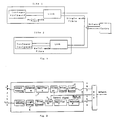
- Figure 1 is a basic diagram of the arrangement according to the invention, and
- Figure 2 shows an embodiment of the invention.
- Figure 1 shows an overview of the application of the present invention. The customer application consists of equipment which is located in different sites and the customer wishes to be able to communicate between these. The customer equipment is in this case adapted for communication in a multi-mode fibre. In data communication, multi-mode fibre is the type generally found. Since the multi-mode fibre has a bigger core, approximately 50 µm, it is easier to build inexpensive optical transmitters and to join such fibres. However, multi-mode fibre has worse transmission characteristics than single-mode fibre, with the result that multi-mode fibre is not suitable for telecommunication.
- The Televerket network therefore utilizes single-mode fibre with a small core, approximately 10 µm. This type of fibre was originally more expensive to produce, but the fibre is now less expensive than multi-mode fibre due to the large amounts of fibre which are used in the telecommunication network.
- Due to the different core sizes of the fibre types, it is not possible to couple these directly together without great losses. For this reason, multi-mode fibre has been previously installed for producing the communication in Figure 1 between equipment of multi-mode type despite the existing single-mode fibre network.
- Figure 2 shows an embodiment of the arrangement which forms a link between a multi-mode connection and the single-mode fibre. The arrangement is divided into two channels, a transmitting
channel 1 and a receivingchannel 2. The customer equipment is coupled by means of multi-mode fibres 3 to the single-mode fibres 4 via the arrangement. The transmitting channel comprises avariable amplifier 5 and atransmitter 6. - The transmitting channel also comprises a
detector 9 for receiving signals from the customer equipment which are transmitted via the multi-mode connection 3. Thedetector 9 converts the optical signals into electrical signals which are fed to theamplifier 5. The receiving channel also comprises an amplifier 7, adetector 8 and a transmitter 11. Theamplifiers 5 and 7 are analog amplifiers with a wide bandwidth. Moreover, they must be direct-current coupled. The characteristics of the amplifiers mean that the arrangement can be used regardless of the signal protocol of the equipment since the signals are converted completely linearly. Thetransmitters 6 and 11 convert the signals from the amplifier into light signals which are transmitted in the respective fibre. - The equipment communicates with another equipment located at a distance, which other equipment is connected to the single-mode fibre via a similar arrangement. The signals are received by the
detector 8 which converts the light signals into electrical signals. The amplifier 7 has a gain which is adapted in such a manner that the electrical signals from thedetector 8 are converted to the same electrical signals which were fed to theamplifier 5. When the arrangement is coupled in, the gain of the amplifiers is finely adjusted so that the link becomes completely transparent. Here, too, the arrangement comprises a transmittingchannel 1 and a receivingchannel 2. - According to the invention, the transmitting and receiving channels each comprise an electrical filter. The aim of the filter is to limit the bandwidth of the arrangement. The bandwidth can also be limited by the choice of amplifier. By determining the bandwidth of the arrangement, the transmission capacity of the arrangement is controlled. This also provides control over the customer's use of the network and makes it possible to charge the customer afterwards.
- According to the invention, the bandwidth of the
filters 10 can be controlled from a centre which controls the network. - The control signals can be transmitted via the single-mode fibres of the network by using multiplex circuits, for example for wavelength multiplex or via electrically coded signals which are transmitted via the fibres. The invention thus makes it possible to offer general links with adjustable transmission capacity. The links are adjusted as required by the customer and charged thereafter.
- The arrangement according to the invention thus enables the customer to be charged in accordance with the transmission capacity of the link.
- Some preferred embodiments of the present invention have been described above. The invention is limited only by the patent claims below.
Claims (7)
- A telecommunications network, for the duplex transmission of data, and arranged so that a first data signal can be modulated on an optical carrier and launched into a multi-mode fibre, and an optical carrier modulated with a second data signal can be demodulated to extract the second data signal, characterised in that said telecommunications network includes a monomode optical transmission path and a convertor for transferring a data signal from a multi-mode optical fibre to a single mode optical fibre and vice versa, said convertor being transparent to optical carrier, or signal modulation, format, said convertor having first means for converting (9, 5), a modulated optical carrier received from a multi-mode optical fibre into a first electric signal, a first optical transmitter (6), for converting said first electric signal to a signal modulated on an optical carrier launched into a mono-mode optical fibre, second means for converting (8, 7), an optical carrier modulated with a data signal received from a mono-mode optical fibre into a second electric signal, a second optical transmitter for converting said second electric signal into an optical carrier modulated with a data signal launched into a multi-mode optical fibre, and means (10), for controlling transmission capacity available for transmission and/or reception over said first and second mono-mode optical fibres.
- A telecommunications network as claimed in claim 1, characterised in that said means (10), for controlling said transmission capacity is a bandwidth filter having a controllable passband.
- A telecommunications network as claimed in claim 2, characterised in that said telecommunications network includes central control means which transmits a signal to said means (10) for controlling said bandwidth filters passband.
- A telecommunications network as claimed in claim 3, characterised in that said central control means is arranged to adjust said bandwidth filters passband in response to a command signal received from a subscriber.
- A telecommunications system as claimed in either claim 3, or 4, characterised in that said signal to said means (10) for controlling said bandwidth filters passband is wavelength division multiplexed onto said mono-mode optical fibre.
- A convertor for use in a telecommunications network as claimed in any of claims 1 to 5, adapted for transferring a data signal from a multi-mode optical fibre to a single mode optical fibre and vice versa, characterised in that said convertor is transparent to optical carrier, or signal modulation, format, said convertor having first means for converting (9, 5), a modulated optical carrier received from a multi-mode optical fibre into a first electric signal, a first optical transmitter (6), for converting said first electric signal to a signal modulated on an optical carrier launched into a mono-mode optical fibre, second means for converting (8, 7), an optical carrier modulated with a data signal received from a mono-mode optical fibre into a second electric signal, a second optical transmitter for converting said second electric signal into an optical carrier modulated with a data signal launched into a multi-mode optical fibre, and means (10), for controlling transmission capacity available for transmission and/or reception over said first and second mono-mode optical fibres.
- A convertor as claimed in claim 6, characterised in that said means (10), for controlling said transmission capacity is a bandwidth filter having a controllable passband.
Applications Claiming Priority (2)
| Application Number | Priority Date | Filing Date | Title |
|---|---|---|---|
| SE8902164 | 1989-06-16 | ||
| SE8902164A SE8902164L (en) | 1989-06-16 | 1989-06-16 | DEVICE FOR MANAGING THE BANDWIDTH OF EQUIPMENT FOR TRANSFER OF SINGLE MODIFIBLE SIGNAL SIGNAL FORMAT |
Publications (3)
| Publication Number | Publication Date |
|---|---|
| EP0403455A2 EP0403455A2 (en) | 1990-12-19 |
| EP0403455A3 EP0403455A3 (en) | 1992-05-13 |
| EP0403455B1 true EP0403455B1 (en) | 1996-11-20 |
Family
ID=20376292
Family Applications (1)
| Application Number | Title | Priority Date | Filing Date |
|---|---|---|---|
| EP19900850187 Expired - Lifetime EP0403455B1 (en) | 1989-06-16 | 1990-05-18 | Arrangement for controlling the bandwidth in equipment for transmitting via singel-mode fibre regardless of signal format |
Country Status (3)
| Country | Link |
|---|---|
| EP (1) | EP0403455B1 (en) |
| DE (1) | DE69029170T2 (en) |
| SE (1) | SE8902164L (en) |
Families Citing this family (4)
| Publication number | Priority date | Publication date | Assignee | Title |
|---|---|---|---|---|
| EP0501946A3 (en) * | 1991-03-01 | 1993-02-03 | Alcatel Austria Aktiengesellschaft | Optical communication system for bidirectional transmission between an exchange and a plurality of subscribers |
| SE518977C2 (en) | 1999-11-22 | 2002-12-17 | Transmode Systems Ab | Arrangements for monitoring and / or controlling the bit rate of data pulses |
| DE10202143A1 (en) | 2002-01-21 | 2003-08-14 | Siemens Ag | Arrangement and method for limiting transmission capacity on a data transmission link |
| CN108155943B (en) * | 2016-12-06 | 2021-01-08 | 北京旋极信息技术股份有限公司 | Optical fiber transmission relay method, device and system |
Family Cites Families (2)
| Publication number | Priority date | Publication date | Assignee | Title |
|---|---|---|---|---|
| GB2113035B (en) * | 1981-12-03 | 1985-10-09 | Standard Telephones Cables Ltd | Optical transmission system and method |
| US4694471A (en) * | 1986-05-05 | 1987-09-15 | Blesser Barry A | Digital data communicating |
-
1989
- 1989-06-16 SE SE8902164A patent/SE8902164L/en not_active Application Discontinuation
-
1990
- 1990-05-18 DE DE1990629170 patent/DE69029170T2/en not_active Expired - Fee Related
- 1990-05-18 EP EP19900850187 patent/EP0403455B1/en not_active Expired - Lifetime
Also Published As
| Publication number | Publication date |
|---|---|
| EP0403455A2 (en) | 1990-12-19 |
| EP0403455A3 (en) | 1992-05-13 |
| SE8902164L (en) | 1990-12-17 |
| SE8902164D0 (en) | 1989-06-16 |
| DE69029170D1 (en) | 1997-01-02 |
| DE69029170T2 (en) | 1997-03-20 |
Similar Documents
| Publication | Publication Date | Title |
|---|---|---|
| EP0512642B1 (en) | Optical transceiver arrangement | |
| US5777763A (en) | In-line optical wavelength reference and control module | |
| US4801190A (en) | Two-way optical fiber transmission network | |
| US4763326A (en) | Service-integrating, digital message transmission system for joint transmission of narrow-band and broadband signals | |
| MXPA04010689A (en) | Access method and connection system by means of optical fiber using dwdm/scm hybrid techniques between base stations and remote antennas in a radiocommunication system. | |
| EP0266870A2 (en) | Local area network with a common carrier signal | |
| AU622523B2 (en) | Optical subscriber loop system | |
| AU629749B2 (en) | Single wavelength bidirectional optical fiber communication link | |
| US4957339A (en) | Optical communication system, particularly in the subscriber area | |
| EP0690651A2 (en) | Network comprising a space division photonic switch and a terminal | |
| CA1160771A (en) | Service integrated, digital transmission system | |
| US5483368A (en) | Optical communication system suitable for selective reception of multiple services | |
| HU212549B (en) | Method for two-way data transmission and communication system for realizing said method | |
| WO1986005649A1 (en) | Optical networks | |
| EP0408861B1 (en) | Polarization control of bidirectionally transmitted beams by a single polarization controller | |
| EP0403455A2 (en) | Arrangement for controlling the bandwidth in equipment for transmitting via singel-mode fibre regardless of signal format | |
| JPH07264160A (en) | Communication network and communication station | |
| US5068847A (en) | Fiber optic network architecture having data feedback for monitoring communications thereon | |
| NZ235720A (en) | Optical signal repeater uses optical/electrical/optical link | |
| JP2594191B2 (en) | Mobile communication system | |
| EP0950297B1 (en) | A bidirectional router and a method of monodirectional amplification | |
| JPS63211836A (en) | Communications system | |
| KR200380894Y1 (en) | Integrated Optical Transmission System for Communication and Broadcasting Signals | |
| JPS63227139A (en) | Communications system | |
| JPH0548534A (en) | Optical communication system |
Legal Events
| Date | Code | Title | Description |
|---|---|---|---|
| PUAI | Public reference made under article 153(3) epc to a published international application that has entered the european phase |
Free format text: ORIGINAL CODE: 0009012 |
|
| AK | Designated contracting states |
Kind code of ref document: A2 Designated state(s): BE CH DE FR GB LI |
|
| PUAL | Search report despatched |
Free format text: ORIGINAL CODE: 0009013 |
|
| AK | Designated contracting states |
Kind code of ref document: A3 Designated state(s): BE CH DE FR GB LI |
|
| 17P | Request for examination filed |
Effective date: 19920703 |
|
| 17Q | First examination report despatched |
Effective date: 19940524 |
|
| RAP1 | Party data changed (applicant data changed or rights of an application transferred) |
Owner name: TELIA AB |
|
| GRAG | Despatch of communication of intention to grant |
Free format text: ORIGINAL CODE: EPIDOS AGRA |
|
| GRAH | Despatch of communication of intention to grant a patent |
Free format text: ORIGINAL CODE: EPIDOS IGRA |
|
| GRAH | Despatch of communication of intention to grant a patent |
Free format text: ORIGINAL CODE: EPIDOS IGRA |
|
| GRAA | (expected) grant |
Free format text: ORIGINAL CODE: 0009210 |
|
| AK | Designated contracting states |
Kind code of ref document: B1 Designated state(s): BE CH DE FR GB LI |
|
| REG | Reference to a national code |
Ref country code: CH Ref legal event code: NV Representative=s name: A. BRAUN, BRAUN, HERITIER, ESCHMANN AG PATENTANWAE |
|
| REF | Corresponds to: |
Ref document number: 69029170 Country of ref document: DE Date of ref document: 19970102 |
|
| ET | Fr: translation filed | ||
| PLBE | No opposition filed within time limit |
Free format text: ORIGINAL CODE: 0009261 |
|
| STAA | Information on the status of an ep patent application or granted ep patent |
Free format text: STATUS: NO OPPOSITION FILED WITHIN TIME LIMIT |
|
| 26N | No opposition filed | ||
| PGFP | Annual fee paid to national office [announced via postgrant information from national office to epo] |
Ref country code: FR Payment date: 19990402 Year of fee payment: 10 |
|
| PGFP | Annual fee paid to national office [announced via postgrant information from national office to epo] |
Ref country code: DE Payment date: 19990420 Year of fee payment: 10 |
|
| PGFP | Annual fee paid to national office [announced via postgrant information from national office to epo] |
Ref country code: CH Payment date: 19990507 Year of fee payment: 10 |
|
| PGFP | Annual fee paid to national office [announced via postgrant information from national office to epo] |
Ref country code: BE Payment date: 19990526 Year of fee payment: 10 |
|
| PGFP | Annual fee paid to national office [announced via postgrant information from national office to epo] |
Ref country code: GB Payment date: 20000221 Year of fee payment: 11 |
|
| PG25 | Lapsed in a contracting state [announced via postgrant information from national office to epo] |
Ref country code: LI Free format text: LAPSE BECAUSE OF NON-PAYMENT OF DUE FEES Effective date: 20000531 Ref country code: CH Free format text: LAPSE BECAUSE OF NON-PAYMENT OF DUE FEES Effective date: 20000531 Ref country code: BE Free format text: LAPSE BECAUSE OF NON-PAYMENT OF DUE FEES Effective date: 20000531 |
|
| BERE | Be: lapsed |
Owner name: TELIA A.B. Effective date: 20000531 |
|
| REG | Reference to a national code |
Ref country code: CH Ref legal event code: PL |
|
| PG25 | Lapsed in a contracting state [announced via postgrant information from national office to epo] |
Ref country code: FR Free format text: LAPSE BECAUSE OF NON-PAYMENT OF DUE FEES Effective date: 20010131 |
|
| PG25 | Lapsed in a contracting state [announced via postgrant information from national office to epo] |
Ref country code: DE Free format text: LAPSE BECAUSE OF NON-PAYMENT OF DUE FEES Effective date: 20010301 |
|
| REG | Reference to a national code |
Ref country code: FR Ref legal event code: ST |
|
| PG25 | Lapsed in a contracting state [announced via postgrant information from national office to epo] |
Ref country code: GB Free format text: LAPSE BECAUSE OF NON-PAYMENT OF DUE FEES Effective date: 20010518 |
|
| GBPC | Gb: european patent ceased through non-payment of renewal fee |
Effective date: 20010518 |