EP0402849A2 - Manipulator - Google Patents
Manipulator Download PDFInfo
- Publication number
- EP0402849A2 EP0402849A2 EP90111077A EP90111077A EP0402849A2 EP 0402849 A2 EP0402849 A2 EP 0402849A2 EP 90111077 A EP90111077 A EP 90111077A EP 90111077 A EP90111077 A EP 90111077A EP 0402849 A2 EP0402849 A2 EP 0402849A2
- Authority
- EP
- European Patent Office
- Prior art keywords
- manipulator
- articulations
- terminal
- articulation
- value
- Prior art date
- Legal status (The legal status is an assumption and is not a legal conclusion. Google has not performed a legal analysis and makes no representation as to the accuracy of the status listed.)
- Granted
Links
Images


Classifications
-
- G—PHYSICS
- G05—CONTROLLING; REGULATING
- G05B—CONTROL OR REGULATING SYSTEMS IN GENERAL; FUNCTIONAL ELEMENTS OF SUCH SYSTEMS; MONITORING OR TESTING ARRANGEMENTS FOR SUCH SYSTEMS OR ELEMENTS
- G05B19/00—Programme-control systems
- G05B19/02—Programme-control systems electric
- G05B19/18—Numerical control [NC], i.e. automatically operating machines, in particular machine tools, e.g. in a manufacturing environment, so as to execute positioning, movement or co-ordinated operations by means of programme data in numerical form
- G05B19/19—Numerical control [NC], i.e. automatically operating machines, in particular machine tools, e.g. in a manufacturing environment, so as to execute positioning, movement or co-ordinated operations by means of programme data in numerical form characterised by positioning or contouring control systems, e.g. to control position from one programmed point to another or to control movement along a programmed continuous path
-
- B—PERFORMING OPERATIONS; TRANSPORTING
- B25—HAND TOOLS; PORTABLE POWER-DRIVEN TOOLS; MANIPULATORS
- B25J—MANIPULATORS; CHAMBERS PROVIDED WITH MANIPULATION DEVICES
- B25J9/00—Programme-controlled manipulators
- B25J9/16—Programme controls
- B25J9/1602—Programme controls characterised by the control system, structure, architecture
- B25J9/161—Hardware, e.g. neural networks, fuzzy logic, interfaces, processor
-
- G—PHYSICS
- G05—CONTROLLING; REGULATING
- G05B—CONTROL OR REGULATING SYSTEMS IN GENERAL; FUNCTIONAL ELEMENTS OF SUCH SYSTEMS; MONITORING OR TESTING ARRANGEMENTS FOR SUCH SYSTEMS OR ELEMENTS
- G05B19/00—Programme-control systems
- G05B19/02—Programme-control systems electric
- G05B19/42—Recording and playback systems, i.e. in which the programme is recorded from a cycle of operations, e.g. the cycle of operations being manually controlled, after which this record is played back on the same machine
- G05B19/427—Teaching successive positions by tracking the position of a joystick or handle to control the positioning servo of the tool head, master-slave control
-
- G—PHYSICS
- G05—CONTROLLING; REGULATING
- G05B—CONTROL OR REGULATING SYSTEMS IN GENERAL; FUNCTIONAL ELEMENTS OF SUCH SYSTEMS; MONITORING OR TESTING ARRANGEMENTS FOR SUCH SYSTEMS OR ELEMENTS
- G05B2219/00—Program-control systems
- G05B2219/30—Nc systems
- G05B2219/34—Director, elements to supervisory
- G05B2219/34065—Fuzzy logic, controller
-
- G—PHYSICS
- G05—CONTROLLING; REGULATING
- G05B—CONTROL OR REGULATING SYSTEMS IN GENERAL; FUNCTIONAL ELEMENTS OF SUCH SYSTEMS; MONITORING OR TESTING ARRANGEMENTS FOR SUCH SYSTEMS OR ELEMENTS
- G05B2219/00—Program-control systems
- G05B2219/30—Nc systems
- G05B2219/37—Measurements
- G05B2219/37357—Force, pressure, weight or deflection
-
- G—PHYSICS
- G05—CONTROLLING; REGULATING
- G05B—CONTROL OR REGULATING SYSTEMS IN GENERAL; FUNCTIONAL ELEMENTS OF SUCH SYSTEMS; MONITORING OR TESTING ARRANGEMENTS FOR SUCH SYSTEMS OR ELEMENTS
- G05B2219/00—Program-control systems
- G05B2219/30—Nc systems
- G05B2219/37—Measurements
- G05B2219/37425—Distance, range
-
- G—PHYSICS
- G05—CONTROLLING; REGULATING
- G05B—CONTROL OR REGULATING SYSTEMS IN GENERAL; FUNCTIONAL ELEMENTS OF SUCH SYSTEMS; MONITORING OR TESTING ARRANGEMENTS FOR SUCH SYSTEMS OR ELEMENTS
- G05B2219/00—Program-control systems
- G05B2219/30—Nc systems
- G05B2219/37—Measurements
- G05B2219/37572—Camera, tv, vision
-
- Y—GENERAL TAGGING OF NEW TECHNOLOGICAL DEVELOPMENTS; GENERAL TAGGING OF CROSS-SECTIONAL TECHNOLOGIES SPANNING OVER SEVERAL SECTIONS OF THE IPC; TECHNICAL SUBJECTS COVERED BY FORMER USPC CROSS-REFERENCE ART COLLECTIONS [XRACs] AND DIGESTS
- Y10—TECHNICAL SUBJECTS COVERED BY FORMER USPC
- Y10S—TECHNICAL SUBJECTS COVERED BY FORMER USPC CROSS-REFERENCE ART COLLECTIONS [XRACs] AND DIGESTS
- Y10S706/00—Data processing: artificial intelligence
- Y10S706/90—Fuzzy logic
Definitions
- the present invention generally relates to a manipulator, and more particularly to a fuzzy control method and apparatus for a manipulator, and a manipulator system using the method and apparatus.
- each articulation angle is obtained through geometric coordinate transformation on the basis of a given position/orientation of the manipulator terminal or tip, as described in Chapter III of "Robot Manipulator” by R.P. Pole, translated by Kunio Yoshikawa, published in September, 1984 by Corona Shuppan K.K. If the dynamic characteristics, e.g., vibrations of a manipulator are also to be controlled, a model is formulated and a complicated formula is solved, as described in Japanese Patent Laid-open Publication JP-A-62-235602.
- the above conventional technique requires a voluminous calculation for the determination of command values to articulations of a manipulator, resulting in a problem of a long sampling time starting from measuring a position with a sensor to fetching the calculation results.
- Another significant subject is to process a so-called singular point which has a value 0 at the denominator of a formula. Further, since a manipulator system is expressed by formulas, these formulas are required to change with environmental conditions and control conditions.
- a fuzzy control method and apparatus for a manipulator and a manipulator system using the method and apparatus, wherein a manipulator fuzzy control is executed by determining command values for articulation angles in such a manner that fuzzy inference is replaced with a part of, or whole of, matrix operations in order to make small the amount of calculations, and the fuzzy inference is executed by using not the absolute value of a target value (destination coordinate value) but a finite difference between the target and actual values of the position/orientation of the manipulator terminal to flexibly deal with a change in environmental conditions.
- fuzzy inference is executed by using only comparison operation and proportion operation, i.e., four fundamental arithmetic operations. Therefore, the amount of calculations can be reduced considerably as compared with the matrix operation for coordinate transformation including trigonometric function operation. Fuzzy inference is conducted by using a finite difference, i.e., a relative value, between the target and actual values of the manipulator terminal. It is therefore always possible to ultimately reach the target value even if there is an error from an ideal state, such as a deformation of an arm. In obtaining the results of fuzzy inference, the denominator for a division operation is the sum of membership functions. Therefore, there is no singular point which leads to no solution.
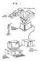
- Fig. 1 is a perspective view of the manipulator system according to the first embodiment of this invention, the manipulator system being realized by the fuzzy control method and apparatus for a manipulator of this invention.
- the manipulator system is constructed of three fundamental sections including a manipulator 201, central processing unit 202 and input/output (I/O) device 203.
- the manipulator 201 is constructed of five articulations and a gripper 306 at the terminal or distal end thereof.
- Reference numeral 501 represents a positioning pointer for the manipulator 201.
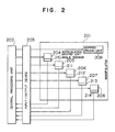
- Fig. 2 is a functional block diagram of the manipulator system shown in Fig. 5.
- Each of the five articulations of the manipulator 201 houses therein corresponding one of articulation driving units 204 to 208 and corresponding one of angle sensors 210 to 214.
- the gripper 306 houses therein a gripper driving unit 209.
- the central processing unit 202 executes all necessary arithmetic operations for the manipulator system, and outputs a command value for each articulation and gripper 306 of the manipulator 201.
- Command values are supplied via the I/O device 203 to the articulation driving units 204 to 208 and gripper driving unit 209 to move the articulations and gripper 306.
- the angle of each articulation is detected with a corresponding one of the angle sensors 210 to 214, and sent to the central processing unit 202 via the I/O device 203.
- Fig. 3 is a diagram showing the structure of the manipulator 201 shown in Fig. 1 (Fig. 2).
- the five articulations of the manipulator 201 are named, from the base or proximal end of the manipulator, a first articulation 301, second articulation 302, third articulation 303, fourth articulation 304, and fifth articulation 305.
- the gripper 306 At the terminal or distal end of the manipulator 201, there is mounted the gripper 306 for holding an object work.
- the arm length from the proximal end of the manipulator 201 to the second articulation 301 is represented by al, that from the second articulation 302 to third articulation 303 by a2, that from the third articulation 303 to fourth articulation 304 by a3, and that from the fourth articulation 304 to the fifth articulation 305 by a4.
- the base of the manipulator 201 is used as the origin, the direction extending vertically from the back to the front of the drawing, as the x-axis, the direction extending to the right, as the y-axis, and the direction extending upward, as the x-axis.
- the angles of the first to fifth articulations 301 to 305 are represented by ⁇ 1 to ⁇ 5.
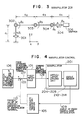
- Fig. 4 is the control block diagram of the control system for the manipulator system shown in Fig. 1 (Figs. 2 and 3).
- a target value 106 of the position/orientation of the terminal of the manipulator 201 is subtracted by an actual value 110 of the position/orientation of the manipulator terminal, to thereby obtain a finite difference 107 of the position/orientation of the manipulator terminal.
- command values 108 for the articulations 301 to 305 of the manipulator 201 are obtained by means of fuzzy inference, and inputted to the articulation driving units 204 to 208 to drive the manipulator 201 accordingly.
- Respective articulation angles 109 detected with the angle sensors 210 to 214 of the manipulator 201 are subjected to coordinate transformation so that the actual value 110 of the position/orientation of the manipulator terminal can be obtained.
- the terminal position of the manipulator 201 is determined by means of rotational coordinate transformation for the articulations 301 to 305 and by means of parallel displacement according to the lengths between the articulations. Accordingly the x-, y-, and z-axis coordinates X, Y, and Z of the terminal position of the manipulator 201 are given by the following equations (1):
- the orientation of the manipulator terminal is represented by the following equations (2): where ⁇ represents an inclination angle of the axis of the gripper 306 relative to the x-y plane, and ⁇ represents a rotational angle around the axis of the gripper 306.
- fuzzy inference 101 shown in Fig. 4 will be described next.
- Various types of fuzzy rules are available because of high redundancy of fuzzy inference 101.
- One example will begiven in the following. It is assumed that the terminal of the manipulator 201 operates at the position forwardly of the first articulation 301, i.e., at the position forwardly of the first articulation 301, i.e., at the position having the positive coordinate value Y in Fig. 3. If the finite difference of the first articulation 301 is a large positive value in the x-axis direction, the first articulation 301 is rotated by a large positive amount to trace the object value.
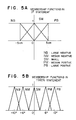
- Figs. 5A and 5B show the membership functions of fuzzy inference 101 shown in Fig. 4, wherein Fig. 5A shows the membership functions for "IF" statement and Fig. 5B shows the membership functions for "THEN" statement.
- the membership function of PB in "IF" statement takes a value 0 for a negative finite difference ⁇ X, increases the value as ⁇ X increases from 0 to 5 cm, and takes a value 1 for ⁇ X ⁇ 5 cm.
- the membership function of NB is a function symmetrical of the membership function of PB relative to the vertical axis.
- the membership functions of PB, PM, SM, NM, and NB in "THEN" statement take values as shown. PM represents a positive medium amount, and NM represents a negative medium amount.
- Fuzzy rules for the second articulation 302 may be expressed by:
- the command value ⁇ 2 to the second articulation 302 is therefore given by:
- the reason for weighting the finite difference ⁇ Z greater than ⁇ Y is that the articulation angle ⁇ 2 of the manipulator 201 has, in many cases, larger influence upon the y-axis components than the z-axis components.
- the degree of influence depends on the angle ⁇ 2. Therefore, if the magnitude of is introduced in "IF" statement of a fuzzy rule, the operation of a computer can be made to converge faster.
- fuzzy rules for the command values ⁇ 3 to ⁇ 5 to the third to fifth articulations 303 to 305 may be expressed by: to obtain the command values 108 to the articulations 301 to 305 and control the manipulator 201.
- the positions X, Y and Z of the articulations ⁇ 1, ⁇ 2, and ⁇ 3 near the base of the manipulator are weighted greater than those of the articulations ⁇ 4 and ⁇ 5 near the manipulator terminal.
- articulations near the terminal rather than articulations near the base are made to have a more important role in the orientation control of the manipulator, whereas for the position control of the manipulator, articulations near the base and not near the terminal are made to have a more important role.
- articulations ⁇ 1 and ⁇ 2 may be considered near the base and articulations ⁇ 3, ⁇ 4, and ⁇ 5 may be considered near the manipulator terminal for the weighting control of orientation and position.
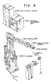
- Fig. 6 is a perspective view of the manipulator system according to the second embodiment of this invention, the manipulator system being realized by the fuzzy control method and apparatus for a manipulator of this invention.
- a manipulator 601 has six articulations with a gripper 603 being mounted at the manipulator terminal.
- a force/torque sensor 602 mounted between the gripper 603 and the manipulator 601 is a force/torque sensor 602 which detects a force/torque.
- a central processing unit 604 executes all arithmetic operations of this system.
- An input/output (I/O) device 605 interfaces between the central processing unit 604 and the manipulator 601.
- Reference numeral 608 represents an object work.
- a TV camera (1) 606 detects the y-direction distance between the gripper 603 and the object work 608 and detects a roll angle deviation.
- Another TV camera (2) 607 detects the x- and z-direction distances between the gripper 603 and the object work 608 and detects a pitch angle and a yaw angle.
- Fig. 7 is a functional block diagram of the manipulator system shown in Fig. 6.
- each of the six articulations of the manipulator 601 houses therein corresponding one of articulation driving units 701 to 706 and corresponding one of angle sensors 708 to 713.
- the gripper 603 houses therein a gripper driving unit 714.
- the central processing unit 604 executes all necessary arithmetic operations for the manipulator system, and outputs a command value for each articulation and gripper 803 of the manipulator 601. Command values are supplied via the I/O device 605 to the articulation driving units 701 to 706 and gripper driving unit 714 to move the articulations and gripper 603.
- the angle of each articulation is detected with a corresponding one of the angle sensors 708 to 713, and sent to the central processing unit 604 via the I/O device 605.
- Signals from the force/torque sensor 602, TV camera (1) 606 and TV camera (2) 607 are also supplied to the central processing unit 604 via the I/O device 605.
- Fig. 8 is a diagram showing the structure of the manipulator 601 shown in Fig. 6 (Fig. 7).
- the six articulations of the manipulator 601 are named, from the base of the manipulator, a first articulation 801, second articulation 802, third articulation 803, fourth articulation 804, fifth articulation 805, and sixth articulation 806.
- the gripper 603. At the terminal of the manipulator 601, there is mounted the gripper 603.
- the x-, y-, and z- axes of the reference coordinate system of the manipulator 601 are defined as shown in Fig. 8, and the origin is at the base of the manipulator 601.
- the angles of the first to sixth articulations are represented by ⁇ 1 to ⁇ 6.
- the manipulator 601 is first moved to reach near the target value by the similar control method as described with the first embodiment shown in Fig. 1.
- Fuzzy rules for fuzzy inference of the manipulator 601 having six articulations 801 to 806 are given by:
- the definition of X, Y, Z, ⁇ , ⁇ , and ⁇ 1 to ⁇ 5 is similar to that of the first embodiment shown in Fig. 1 to 5.
- ⁇ is one of parameters representative of the orientation of the terminal of the manipulator 601, and it represents the angle, relative to the y-axis, of the terminal image projected upon the x-y plane.
- ⁇ 6 is the angle of the sixth articulation 806 of the manipulator 601. Fuzzy rules are described by using only positive rules.
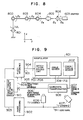
- reference numeral 901 represents fuzzy inference
- 902 an image processor
- 903 a finite difference of the position/orientation at the manipulator terminal
- 904 a command value to each manipulator articulation
- 905 an angle of each manipulator articulation
- 906 a force/torque at the manipulator terminal
- 907 a force/torque in the tip coordinate system
- 908 coordinate transformation 909 a finite difference of a force/torque
- 910 a target value of a force/torque
- 911 a video signal.
- the main different of the embodiment shown in Fig. 9 from that of Fig. 1 is that the finite difference 903 of the position/orientation at the terminal of the manipulator 601 is obtained by image-processing 902 the video signals 911 from the TV cameras 606 and 607.
- fuzzy inference 901 For the control of determination of only the position of the manipulator 601 shown in Fig. 9, the above-described fuzzy rules can be used for executing fuzzy inference 901. However, in this embodiment, since a compliance motion incorporating the force/torque control is carried out, there is added to fuzzy inference 901 an inference on the basis of the finite difference 909 of the force/torque. This force torque finite difference is obtained in the following manner. A force/torque signal 907 in the tip coordinate system outputted from the force/torque sensor 602 is subjected to coordinate transformation 908.
- fuzzy rules to be added fuzzy inference 901 in order to execute the compliance motion are shown.
- ⁇ X is SM and ⁇ Y is SM and ⁇ Z is SM and ⁇ is SM and ⁇ B is SM and ⁇ is SM, are expressed by ⁇ TCP is SM, then fuzzy rules are given by:
- introducing fuzzy inference for the control of a manipulator allows to realize a desired control, even if an additional control parameter is added, without changing the original rules. Therefore, controls such as a control to take the dynamic characteristics into consideration, a control to aim at reducing a power consumption, a control to suppress vibration of an arm, or the like, may be readily realized by simply adding new rules.
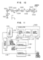
- Fig. 10 is a diagram showing the structure of the manipulator system with seven articulations and redundant degree of freedom according to the third embodiment of this invention, the manipulator system being realized by the fuzzy control method and apparatus for a manipulator of this invention.
- reference numeral 1000 represents a manipulator, 1001 to 1007 first to seventh articulations, 1008 a gripper, and 1009 an ultrasonic sensor.
- ⁇ 1 to ⁇ 7 represent the angles of the articulations 1001 to 1007.
- This embodiment features first in that the manipulator articulations with redundant degree of freedom allow a smooth motion of the manipulator tip or terminal, and second in that seven articulations 1001 to 1007 are disposed such that even if one of the seven articulations 1001 to 1007 of the manipulator 1000 has a trouble, the remaining six articulations can cover the operation area as broad as possible.
- the ultrasonic sensor 1009 is mounted at the manipulator terminal to measure the distance and direction to an object work to be held by the gripper 1008.
- Fig. 11 is a control block diagram of the manipulator system shown in Fig. 10.
- the ultrasonic sensor 1118 (1009) measures a distance/direction 1123 to the object work to be held by the gripper 1008 mounted at the manipulator terminal.
- the obtained distance/direction 1123 is subjected to coordinate transformation 1103 to obtain the finite difference of the position/orientation at the manipulator terminal.
- fuzzy inference 1101 is executed.
- the manipulator 1000 has seven articulations 1001 to 1007, while the position/orientation of the manipulator terminal is made coincident with the target value, there still remain another element to be operated freely in the geometric sense.
- the articulation angles 1121 detected with angle sensors 1111 to 1117 of the articulations 1001 to 1007 of the manipulator 1000 are subjected to coordinate transformation 1102 to thereby obtain the position 1122 of the fourth articulation 1004.
- a distance 1124 between the obstacle and the forth articulation is obtained and used as a parameter for fuzzy inference 1101.
- fuzzy inference 1101 is executed to obtain command values 1120 for the articulations 1001 to 1007 of the manipulator 1000 and supply them to articulation driving units 1104 to 1110.
- fuzzy rules for the first to third articulations 1001 to 1003 of the manipulator 1000 are set such that the finite difference of the position of the manipulator terminal is made small, whereas fuzzy rules for the fifth to seventh articulations are set such that the finite difference of the orientation of the manipulator terminal is made small.
- a fuzzy rule for the fourth articulation 1004 is set such that the finite differences of both position and orientation are made small.
- fuzzy rules for getting away from an obstacle are set with respect to the second articulation 1002 such that the y- and z-axis components of the distance 1124 between the obstacle and the fourth articulation 1004 are made large.
- Such fuzzy fules in this embodiment are given by: wherein the membership function PS represents a small positive amount, and the membership function NS represents a small negative amount.
- Fig. 12 is a schematic diagram showing a master-slave manipulator system according to the fourth embodiment of this invention, the system being realized by the fuzzy control method and apparatus for a manipulator of this invention.
- a central processing unit 1201 executes all arithmetic operations for the system.
- the central processing unit 1201 outputs, via a master arm input/output (I/O) device 1202, command values to articulations of a master arm 1204 for the control of the articulations.
- the articulation angles detected with articulation angle sensors are supplied via the master arm I/O device 1202 to the central processing unit 1201.
- a force/torque detected with a force/torque sensor 1206 mounted at the terminal of the master arm 1204 is supplied via the master arm I/O device 1202 to the central processing unit 1202.
- the central processing unit 1201 outputs, via a slave arm input/output (I/O) device 1203, command values to articulations of the slave arm 1205 for the control of the articulations.
- the articulation angles detected with articulation angle sensors are supplied via the slave arm I/O device 1203 to the central processing unit 1201.
- a force/torque detected with a force/torque sensor 1207 mounted at the terminal of the slave arm 1205 is supplied via the slave arm I/O device 1203 to the central processing unit 1202.
- the master and slave arms 1204 and 1205 each have six articulations, so six command values and six articulation angles are supplied to the articulations.
- Fig. 13 is a functional block diagram of the manipulator system shown in Fig. 12.
- articulation driving units 1301 to 1306 are mounted on the first to sixth articulations of the master arm 1204 to control the master arm 1204.
- the articulation angles are detected with the angle sensors 1307 to 1312 mounted on the first to sixth articulations.
- articulation driving units 1314 to 1319 are mounted on the first to sixth articulations of the slave arm 1205 to control the slave arm 1205.
- the articulation angles are detected with the angle sensors 1320 to 1325.
- Fig. 14 is the control block diagram of the manipulator system shown in Fig. 12 (Fig. 13).
- the control system of the manipulator system basically executes a force feedback bilateral servo control.
- the articulation angles 1407 detected with the angle sensors 1307 to 1312 of the master arm 1204 are subjected to coordinate transformation (I) 1401 to thereby obtain the position/orientation 1408 of the master arm terminal.
- the articulation angles 1409 detected with the angle sensors 1320 to 1325 of the slave arm 1205 are subjected to coordinate transformation (II) 1420 to thereby obtain the position/orientation 1410 of the slave arm terminal.
- This master-slave manipulator aims at causing the slave arm 1205 to move in coincidence with, or following, the position/orientation of the terminal of the master arm 1204. Therefore, it is necessary to make the position/orientation of the master arm terminal coincident with that of the slave arm terminal.
- the finite difference 1411 of the position/orientation by the amount of which the salve arm 1205 should move is obtained by subtracting the position/orientation 1408 by the position/orientation 1410.
- fuzzy inference 1403 is executed by using similar fuzzy rules as described with the position/orientation of the terminal of the manipulator 601 of the second embodiment shown in Fig. 6 (Fig. 9).
- the obtained command values 1412 to articulations of the slave arm 1205 are supplied to drive the articulation driving units 1314 to 1319 to move the slave arm 1205.
- Driving the master arm 1204 is so performed in the following manner that an operator is given a force which the slave arm 1205 receives.
- the force/torque signal 1413 from the force/torque sensor 1206 mounted at the terminal of the master arm 1204 is a force/torque signal described with the coordinate system of the force/torque sensor 1206 itself, i.e., a tip coordinate system of the master arm 1204.
- This force/torque is subjected to coordinate transformation (III) to obtain a force/torque represented by the master arm reference coordinate system.
- the force/torque signal 1415 from the force/torque sensor 1207 on the slave arm 1205 described with the slave arm tip coordinate system is subjected to coordinate transformation (IV) 1405 to obtain the force/torque 1416 described with the slave arm reference coordinate system.
- the finite difference 1417 of the force/torque is obtained by subtracting the force/torque 1416 by the force/torque 1414.
- fuzzy inference 1406 is executed by using similar fuzzy rules for the force/torque as described with the second embodiment.
- the obtained command values 1418 to articulations of the master arm 1204 are supplied to the articulation driving units 1301 to 1306 to drive the master arm 1204.
- fuzzy control using fuzzy inference has been executed for the control of, e.g., six articulations.
- the control of articulations may be made by using a combination of conventional matrix operations and fuzzy reductions.
- matrix operations for coordinate transformation inverse transformation
- fuzzy inference as of this invention is carried out for the remaining articulations.
Abstract
Description
- The present invention generally relates to a manipulator, and more particularly to a fuzzy control method and apparatus for a manipulator, and a manipulator system using the method and apparatus.
- In a conventional manipulator control method, each articulation angle is obtained through geometric coordinate transformation on the basis of a given position/orientation of the manipulator terminal or tip, as described in Chapter III of "Robot Manipulator" by R.P. Pole, translated by Kunio Yoshikawa, published in September, 1984 by Corona Shuppan K.K. If the dynamic characteristics, e.g., vibrations of a manipulator are also to be controlled, a model is formulated and a complicated formula is solved, as described in Japanese Patent Laid-open Publication JP-A-62-235602.
- The above conventional technique requires a voluminous calculation for the determination of command values to articulations of a manipulator, resulting in a problem of a long sampling time starting from measuring a position with a sensor to fetching the calculation results. Another significant subject is to process a so-called singular point which has a value 0 at the denominator of a formula. Further, since a manipulator system is expressed by formulas, these formulas are required to change with environmental conditions and control conditions.
- It is an object of the present invention to provide a fuzzy control method and apparatus for a manipulator, and a manipulator system using the method and apparatus, capable of controlling a manipulator with a small amount of calculations and flexibly dealing with a change in environmental conditions and control conditions.
- It is another object of the present invention to provide a manipulator control method/system capable of reliably executing a sophisticated fuzzy control for a manipulator with a small amount of calculations and without a necessity of higher performance of a computer.
- It is a further object of the present invention to provide a manipulator control method/system capable of dealing with a change in environmental conditions and control conditions, simply by using additional fuzzy rules.
- It is a still further object of the present invention to provide a manipulator control method/system capable of determining the position of the terminal of a manipulator with redundant degree of freedom even if one of articulations enters in malfunction.
- In order to achieve the above objects of the present invention, there is provided a fuzzy control method and apparatus for a manipulator, and a manipulator system using the method and apparatus, wherein a manipulator fuzzy control is executed by determining command values for articulation angles in such a manner that fuzzy inference is replaced with a part of, or whole of, matrix operations in order to make small the amount of calculations, and the fuzzy inference is executed by using not the absolute value of a target value (destination coordinate value) but a finite difference between the target and actual values of the position/orientation of the manipulator terminal to flexibly deal with a change in environmental conditions.
- According to the fuzzy control method and apparatus for a manipulator, and the manipulator system using the method and apparatus, fuzzy inference is executed by using only comparison operation and proportion operation, i.e., four fundamental arithmetic operations. Therefore, the amount of calculations can be reduced considerably as compared with the matrix operation for coordinate transformation including trigonometric function operation. Fuzzy inference is conducted by using a finite difference, i.e., a relative value, between the target and actual values of the manipulator terminal. It is therefore always possible to ultimately reach the target value even if there is an error from an ideal state, such as a deformation of an arm. In obtaining the results of fuzzy inference, the denominator for a division operation is the sum of membership functions. Therefore, there is no singular point which leads to no solution.
-
- Fig. 1 is a perspective view showing the structure of a manipulator system of this invention;
- Fig. 2 is a functional block diagram of the manipulator system;
- Fig. 3 is a diagram showing the structure of the manipulator;
- Fig. 4 is a control block diagram of the manipulator system of this invention;
- Figs. 5A and 5B are diagrams illustrating the membership functions of fuzzy inference;
- Fig. 6 is a perspective view showing a manipulator system according to the second embodiment of this invention;
- Fig. 7 is a functional block diagram of the manipulator system;
- Fig. 8 is a diagram showing the structure of the manipulator;
- Fig. 9 is a control block diagram of the manipulator system;
- Fig. 10 is a diagram showing the structure of a manipulator according to the third embodiment of this invention;
- Fig. 11 is a control block diagram of the manipulator system;
- Fig. 12 is a schematic diagram showing the structure of a manipulator system according to the fourth embodiment of this invention;
- Fig. 13 is a functional block diagram of the manipulator system; and
- Fig. 14 is a control block diagram of the manipulator system.
- Fig. 1 is a perspective view of the manipulator system according to the first embodiment of this invention, the manipulator system being realized by the fuzzy control method and apparatus for a manipulator of this invention. Referring to Fig. 1, the manipulator system is constructed of three fundamental sections including a
manipulator 201,central processing unit 202 and input/output (I/O)device 203. Themanipulator 201 is constructed of five articulations and agripper 306 at the terminal or distal end thereof.Reference numeral 501 represents a positioning pointer for themanipulator 201. - Fig. 2 is a functional block diagram of the manipulator system shown in Fig. 5. Each of the five articulations of the
manipulator 201 houses therein corresponding one ofarticulation driving units 204 to 208 and corresponding one ofangle sensors 210 to 214. Thegripper 306 houses therein agripper driving unit 209. Thecentral processing unit 202 executes all necessary arithmetic operations for the manipulator system, and outputs a command value for each articulation andgripper 306 of themanipulator 201. Command values are supplied via the I/O device 203 to thearticulation driving units 204 to 208 andgripper driving unit 209 to move the articulations andgripper 306. The angle of each articulation is detected with a corresponding one of theangle sensors 210 to 214, and sent to thecentral processing unit 202 via the I/O device 203. - Fig. 3 is a diagram showing the structure of the
manipulator 201 shown in Fig. 1 (Fig. 2). Referring to Fig. 3, the five articulations of themanipulator 201 are named, from the base or proximal end of the manipulator, afirst articulation 301,second articulation 302,third articulation 303,fourth articulation 304, and fifth articulation 305. At the terminal or distal end of themanipulator 201, there is mounted thegripper 306 for holding an object work. The arm length from the proximal end of themanipulator 201 to thesecond articulation 301 is represented by al, that from thesecond articulation 302 tothird articulation 303 by a2, that from thethird articulation 303 tofourth articulation 304 by a3, and that from thefourth articulation 304 to the fifth articulation 305 by a4. As the reference coordinate system of themanipulator 201, the base of themanipulator 201 is used as the origin, the direction extending vertically from the back to the front of the drawing, as the x-axis, the direction extending to the right, as the y-axis, and the direction extending upward, as the x-axis. The angles of the first tofifth articulations 301 to 305 are represented by ϑ₁ to ϑ₅. - Fig. 4 is the control block diagram of the control system for the manipulator system shown in Fig. 1 (Figs. 2 and 3). Referring to Fig. 4, a
target value 106 of the position/orientation of the terminal of themanipulator 201 is subtracted by anactual value 110 of the position/orientation of the manipulator terminal, to thereby obtain a finite difference 107 of the position/orientation of the manipulator terminal. In accordance with the finite difference 107,command values 108 for thearticulations 301 to 305 of themanipulator 201 are obtained by means of fuzzy inference, and inputted to thearticulation driving units 204 to 208 to drive themanipulator 201 accordingly.Respective articulation angles 109 detected with theangle sensors 210 to 214 of themanipulator 201 are subjected to coordinate transformation so that theactual value 110 of the position/orientation of the manipulator terminal can be obtained. - The
coordinate transformation 105 shown in Fig. 5 will be described below. - The terminal position of the
manipulator 201 is determined by means of rotational coordinate transformation for thearticulations 301 to 305 and by means of parallel displacement according to the lengths between the articulations. Accordingly the x-, y-, and z-axis coordinates X, Y, and Z of the terminal position of themanipulator 201 are given by the following equations (1):
- The orientation of the manipulator terminal is represented by the following equations (2):

gripper 306 relative to the x-y plane, and β represents a rotational angle around the axis of thegripper 306. - The method of
fuzzy inference 101 shown in Fig. 4 will be described next. Various types of fuzzy rules are available because of high redundancy offuzzy inference 101. One example will begiven in the following. It is assumed that the terminal of themanipulator 201 operates at the position forwardly of thefirst articulation 301, i.e., at the position forwardly of thefirst articulation 301, i.e., at the position having the positive coordinate value Y in Fig. 3. If the finite difference of thefirst articulation 301 is a large positive value in the x-axis direction, thefirst articulation 301 is rotated by a large positive amount to trace the object value. On the other hand, if the finite difference is small, it is not necessary to cause thefirst articulation 301 to move. If the finite difference has a large negative value, thefirst articulation 301 is rotated by a large negative amount. Fuzzy rules are accordingly given by the following:
- Figs. 5A and 5B show the membership functions of
fuzzy inference 101 shown in Fig. 4, wherein Fig. 5A shows the membership functions for "IF" statement and Fig. 5B shows the membership functions for "THEN" statement. In Fig. 5A, the membership function of PB in "IF" statement takes a value 0 for a negative finite difference ΔX, increases the value as ΔX increases from 0 to 5 cm, and takes avalue 1 for ΔX ≧ 5 cm. The membership function of SM takes avalue 1 for ΔX = 0, and gradually goes to 0 as ΔX goes to +/- 5 cm. The membership function of NB is a function symmetrical of the membership function of PB relative to the vertical axis. In Fig. 5B, the membership functions of PB, PM, SM, NM, and NB in "THEN" statement take values as shown. PM represents a positive medium amount, and NM represents a negative medium amount. - Representing the membership functions of PB, SM, and NB in "IF" statement shown in Fig. 5A by mPB (AX), mSM (ΔX), and mNB (ΔX), respectively, and representing the medians of PB, NB, PM, NM, and SM in "THEN" statement shown in Fig. 5B as TPB, TNB, TPM, TNM, respectively, then the command value Δϑ₁ to the
first articulation 301 is given by:
m (ΔX)
= mPB (ΔX) (ΔX ≧ 0)
= -mNB (ΔX) (ΔX < 0) (5)
Using this membership function m (ΔX), the command value is given by:
- Fuzzy rules for the
second articulation 302 may be expressed by:
- The command value Δϑ₂ to the
second articulation 302 is therefore given by:
manipulator 201 has, in many cases, larger influence upon the y-axis components than the z-axis components. The degree of influence depends on the angle ϑ₂. Therefore, if the magnitude of is introduced in "IF" statement of a fuzzy rule, the operation of a computer can be made to converge faster. - Similarly, fuzzy rules for the command values Δϑ₃ to Δϑ₅ to the third to
fifth articulations 303 to 305 may be expressed by:
articulations 301 to 305 and control themanipulator 201. - In the above representations, the positions X, Y and Z of the articulations ϑ₁, ϑ₂, and ϑ₃ near the base of the manipulator are weighted greater than those of the articulations ϑ₄ and ϑ₅ near the manipulator terminal. In other words, articulations near the terminal rather than articulations near the base are made to have a more important role in the orientation control of the manipulator, whereas for the position control of the manipulator, articulations near the base and not near the terminal are made to have a more important role. Obviously, as a modification, articulations ϑ₁ and ϑ₂ may be considered near the base and articulations ϑ₃, ϑ₄, and ϑ₅ may be considered near the manipulator terminal for the weighting control of orientation and position.
- Fig. 6 is a perspective view of the manipulator system according to the second embodiment of this invention, the manipulator system being realized by the fuzzy control method and apparatus for a manipulator of this invention. Referring to Fig. 6, a
manipulator 601 has six articulations with agripper 603 being mounted at the manipulator terminal. Mounted between thegripper 603 and themanipulator 601 is a force/torque sensor 602 which detects a force/torque. Acentral processing unit 604 executes all arithmetic operations of this system. An input/output (I/O)device 605 interfaces between thecentral processing unit 604 and themanipulator 601.Reference numeral 608 represents an object work. A TV camera (1) 606 detects the y-direction distance between thegripper 603 and theobject work 608 and detects a roll angle deviation. Another TV camera (2) 607 detects the x- and z-direction distances between thegripper 603 and theobject work 608 and detects a pitch angle and a yaw angle. - Fig. 7 is a functional block diagram of the manipulator system shown in Fig. 6. Referring to Fig. 7, each of the six articulations of the
manipulator 601 houses therein corresponding one of articulation driving units 701 to 706 and corresponding one ofangle sensors 708 to 713. Thegripper 603 houses therein agripper driving unit 714. Thecentral processing unit 604 executes all necessary arithmetic operations for the manipulator system, and outputs a command value for each articulation andgripper 803 of themanipulator 601. Command values are supplied via the I/O device 605 to the articulation driving units 701 to 706 andgripper driving unit 714 to move the articulations andgripper 603. The angle of each articulation is detected with a corresponding one of theangle sensors 708 to 713, and sent to thecentral processing unit 604 via the I/O device 605. Signals from the force/torque sensor 602, TV camera (1) 606 and TV camera (2) 607 are also supplied to thecentral processing unit 604 via the I/O device 605. - Fig. 8 is a diagram showing the structure of the
manipulator 601 shown in Fig. 6 (Fig. 7). Referring to Fig. 8, the six articulations of themanipulator 601 are named, from the base of the manipulator, afirst articulation 801, second articulation 802,third articulation 803,fourth articulation 804,fifth articulation 805, andsixth articulation 806. At the terminal of themanipulator 601, there is mounted thegripper 603. The x-, y-, and z- axes of the reference coordinate system of themanipulator 601 are defined as shown in Fig. 8, and the origin is at the base of themanipulator 601. The angles of the first to sixth articulations are represented by ϑ₁ to ϑ₆. - Next, the control system shown in Fig. 7 (Fig. 8) will be described. The
manipulator 601 is first moved to reach near the target value by the similar control method as described with the first embodiment shown in Fig. 1. Fuzzy rules for fuzzy inference of themanipulator 601 having sixarticulations 801 to 806 are given by:
manipulator 601, and it represents the angle, relative to the y-axis, of the terminal image projected upon the x-y plane. ϑ₆ is the angle of thesixth articulation 806 of themanipulator 601. Fuzzy rules are described by using only positive rules. - After the manipulator terminal comes near the target value to a certain degree, signals from TV camera (1) 606 and TV camera (2) 607 are used for ΔX, ΔY, ΔZ, Δα, Δβ, and Δγ. The control system of the manipulator system of Fig. 6 (Figs. 7 and 8) is shown in the control block diagram of Fig. 9. In Fig. 9,
reference numeral 901 represents fuzzy inference, 902 an image processor, 903 a finite difference of the position/orientation at the manipulator terminal, 904 a command value to each manipulator articulation, 905 an angle of each manipulator articulation, 906 a force/torque at the manipulator terminal, 907 a force/torque in the tip coordinate system, 908 coordinate transformation, 909 a finite difference of a force/torque, 910 a target value of a force/torque, and 911 a video signal. The main different of the embodiment shown in Fig. 9 from that of Fig. 1 is that thefinite difference 903 of the position/orientation at the terminal of themanipulator 601 is obtained by image-processing 902 the video signals 911 from theTV cameras - For the control of determination of only the position of the
manipulator 601 shown in Fig. 9, the above-described fuzzy rules can be used for executingfuzzy inference 901. However, in this embodiment, since a compliance motion incorporating the force/torque control is carried out, there is added tofuzzy inference 901 an inference on the basis of thefinite difference 909 of the force/torque. This force torque finite difference is obtained in the following manner. A force/torque signal 907 in the tip coordinate system outputted from the force/torque sensor 602 is subjected to coordinatetransformation 908. As a result, there is obtained a force/torque 906 at the terminal of the manipulator having the forces Fx, Fy, and Fz in the x-, y-, and z-axes and torques τα, τβ, and τγ corresponding the angles α, β, and γ. This force/torque 906 is subtracted from a force/torque target value 910 to obtain the force/torquefinite difference 909. - Next, fuzzy rules to be added
fuzzy inference 901 in order to execute the compliance motion are shown. For the purpose of convenience,
ΔX is SM and ΔY is SM and ΔZ is SM and
Δα is SM and ΔB is SM and Δγ is SM,
are expressed by
ΔTCP is SM,
then fuzzy rules are given by:
- As in the above manner, introducing fuzzy inference for the control of a manipulator allows to realize a desired control, even if an additional control parameter is added, without changing the original rules. Therefore, controls such as a control to take the dynamic characteristics into consideration, a control to aim at reducing a power consumption, a control to suppress vibration of an arm, or the like, may be readily realized by simply adding new rules.
- Fig. 10 is a diagram showing the structure of the manipulator system with seven articulations and redundant degree of freedom according to the third embodiment of this invention, the manipulator system being realized by the fuzzy control method and apparatus for a manipulator of this invention. Referring to Fig. 10,
reference numeral 1000 represents a manipulator, 1001 to 1007 first to seventh articulations, 1008 a gripper, and 1009 an ultrasonic sensor. ϑ₁ to ϑ₇ represent the angles of thearticulations 1001 to 1007. This embodiment features first in that the manipulator articulations with redundant degree of freedom allow a smooth motion of the manipulator tip or terminal, and second in that sevenarticulations 1001 to 1007 are disposed such that even if one of the sevenarticulations 1001 to 1007 of themanipulator 1000 has a trouble, the remaining six articulations can cover the operation area as broad as possible. Theultrasonic sensor 1009 is mounted at the manipulator terminal to measure the distance and direction to an object work to be held by thegripper 1008. - Fig. 11 is a control block diagram of the manipulator system shown in Fig. 10. Referring to Fig. 11, the ultrasonic sensor 1118 (1009) measures a distance/
direction 1123 to the object work to be held by thegripper 1008 mounted at the manipulator terminal. The obtained distance/direction 1123 is subjected to coordinatetransformation 1103 to obtain the finite difference of the position/orientation at the manipulator terminal. In accordance with this finite difference, fuzzy inference 1101 is executed. As described previously, since themanipulator 1000 has sevenarticulations 1001 to 1007, while the position/orientation of the manipulator terminal is made coincident with the target value, there still remain another element to be operated freely in the geometric sense. Therefore, in addition to deal with a possible trouble, another goal of getting away from an obstacle is set to make the distance from thefourth articulation 1004 to the obstacle as far as possible. To this end, the articulation angles 1121 detected withangle sensors 1111 to 1117 of thearticulations 1001 to 1007 of themanipulator 1000 are subjected to coordinatetransformation 1102 to thereby obtain theposition 1122 of thefourth articulation 1004. In accordance with the difference between anobstacle position 1125 and theposition 1122 of the fourth articulation, adistance 1124 between the obstacle and the forth articulation is obtained and used as a parameter for fuzzy inference 1101. Further, since fuzzy rules are to be changed with the conditions of the manipulator articulations, the articulation angles 1121 of themanipulator 1000 are supplied to fuzzy inference 1101. Using these parameters, fuzzy inference 1101 is executed to obtaincommand values 1120 for thearticulations 1001 to 1007 of themanipulator 1000 and supply them toarticulation driving units 1104 to 1110. - Next, there will be described a method of setting fuzzy rules for fuzzy inference 1101 shown in Fig. 11. This method is basically the same as those described with the first and second embodiments. Specifically, fuzzy rules for the first to
third articulations 1001 to 1003 of themanipulator 1000 are set such that the finite difference of the position of the manipulator terminal is made small, whereas fuzzy rules for the fifth to seventh articulations are set such that the finite difference of the orientation of the manipulator terminal is made small. A fuzzy rule for thefourth articulation 1004 is set such that the finite differences of both position and orientation are made small. With the above arrangement, even if one of the first toseventh articulations 1001 to 1007 of themanipulator 1000 will not operate because of an accident, the position/orientation of the terminal of themanipulator 1000 can be made coincident with the target value. Further, fuzzy rules for getting away from an obstacle are set with respect to the second articulation 1002 such that the y- and z-axis components of thedistance 1124 between the obstacle and thefourth articulation 1004 are made large. Such fuzzy fules in this embodiment are given by:
- If one of the first to
seventh articulations 1001 to 1007 has a trouble and the position/orientation of the terminal of themanipulator 1000 is to be made coincident with the target value, then the above-described seven rules are not used. - Fig. 12 is a schematic diagram showing a master-slave manipulator system according to the fourth embodiment of this invention, the system being realized by the fuzzy control method and apparatus for a manipulator of this invention. Referring to Fig. 12, a
central processing unit 1201 executes all arithmetic operations for the system. Thecentral processing unit 1201 outputs, via a master arm input/output (I/O)device 1202, command values to articulations of amaster arm 1204 for the control of the articulations. The articulation angles detected with articulation angle sensors are supplied via the master arm I/O device 1202 to thecentral processing unit 1201. Similarly, a force/torque detected with a force/torque sensor 1206 mounted at the terminal of themaster arm 1204 is supplied via the master arm I/O device 1202 to thecentral processing unit 1202. - In the case of a
slave arm 1205, similar to the above operations, thecentral processing unit 1201 outputs, via a slave arm input/output (I/O)device 1203, command values to articulations of theslave arm 1205 for the control of the articulations. The articulation angles detected with articulation angle sensors are supplied via the slave arm I/O device 1203 to thecentral processing unit 1201. Similarly, a force/torque detected with a force/torque sensor 1207 mounted at the terminal of theslave arm 1205 is supplied via the slave arm I/O device 1203 to thecentral processing unit 1202. The master andslave arms - Fig. 13 is a functional block diagram of the manipulator system shown in Fig. 12. Referring to Fig. 13,
articulation driving units 1301 to 1306 are mounted on the first to sixth articulations of themaster arm 1204 to control themaster arm 1204. The articulation angles are detected with theangle sensors 1307 to 1312 mounted on the first to sixth articulations. Similarly,articulation driving units 1314 to 1319 are mounted on the first to sixth articulations of theslave arm 1205 to control theslave arm 1205. The articulation angles are detected with theangle sensors 1320 to 1325. - Fig. 14 is the control block diagram of the manipulator system shown in Fig. 12 (Fig. 13). The control system of the manipulator system basically executes a force feedback bilateral servo control. Upon operation of the
master arm 1204 by an operator, the articulation angles 1407 detected with theangle sensors 1307 to 1312 of themaster arm 1204 are subjected to coordinate transformation (I) 1401 to thereby obtain the position/orientation 1408 of the master arm terminal. Further, the articulation angles 1409 detected with theangle sensors 1320 to 1325 of theslave arm 1205 are subjected to coordinate transformation (II) 1420 to thereby obtain the position/orientation 1410 of the slave arm terminal. This master-slave manipulator aims at causing theslave arm 1205 to move in coincidence with, or following, the position/orientation of the terminal of themaster arm 1204. Therefore, it is necessary to make the position/orientation of the master arm terminal coincident with that of the slave arm terminal. The finite difference 1411 of the position/orientation by the amount of which thesalve arm 1205 should move, is obtained by subtracting the position/orientation 1408 by the position/orientation 1410. In accordance with the finite difference 1411,fuzzy inference 1403 is executed by using similar fuzzy rules as described with the position/orientation of the terminal of themanipulator 601 of the second embodiment shown in Fig. 6 (Fig. 9). The obtainedcommand values 1412 to articulations of theslave arm 1205 are supplied to drive thearticulation driving units 1314 to 1319 to move theslave arm 1205. - Driving the
master arm 1204 is so performed in the following manner that an operator is given a force which theslave arm 1205 receives. The force/torque signal 1413 from the force/torque sensor 1206 mounted at the terminal of themaster arm 1204 is a force/torque signal described with the coordinate system of the force/torque sensor 1206 itself, i.e., a tip coordinate system of themaster arm 1204. This force/torque is subjected to coordinate transformation (III) to obtain a force/torque represented by the master arm reference coordinate system. In a similar manner, the force/torque signal 1415 from the force/torque sensor 1207 on theslave arm 1205 described with the slave arm tip coordinate system is subjected to coordinate transformation (IV) 1405 to obtain the force/torque 1416 described with the slave arm reference coordinate system. Thefinite difference 1417 of the force/torque is obtained by subtracting the force/torque 1416 by the force/torque 1414. In accordance with the force/torquefinite difference 1417,fuzzy inference 1406 is executed by using similar fuzzy rules for the force/torque as described with the second embodiment. The obtainedcommand values 1418 to articulations of themaster arm 1204 are supplied to thearticulation driving units 1301 to 1306 to drive themaster arm 1204. - In the above embodiments, instead of using matrix operations, fuzzy control using fuzzy inference has been executed for the control of, e.g., six articulations. The control of articulations may be made by using a combination of conventional matrix operations and fuzzy reductions. For example, matrix operations for coordinate transformation (inverse transformation) may be carried out for some of articulations of a manipulator to obtain the articulation angles thereof with a given position/orientation of the manipulator terminal, and fuzzy inference as of this invention is carried out for the remaining articulations.
Claims (16)
destination coordinate means (106) for giving a destination coordinate value of the position and orientation of the terminal of a manipulator;
present coordinate means (105) for giving a present coordinate value of the position and orientation of the terminal of said manipulator;
finite difference generating means (103) connected to said destination coordinate means and said present coordinate means for generating finite differences between said destination coordinate value and said present coordinate value; and
fuzzy inference means (101) connected to said finite difference generating means for executing a fuzzy inference of said finite differences data for at least one of said plurality of articulations.
means (1039) for giving a finite difference set between a destination value and a present value of the position and orientation of the terminal of said manipulator; and
means (101) for determining a command value for each articulation angle by executing a fuzzy inference of said articulations with respect to at least one articulation.
a step of giving a finite difference set between a destination value and a present value of the position and orientation of the terminal of said manipulator; and
a step of executing a fuzzy inference of said articulations with respect to at least one articulation and determining a command value for each articulation angle.
Applications Claiming Priority (2)
| Application Number | Priority Date | Filing Date | Title |
|---|---|---|---|
| JP146569/89 | 1989-06-12 | ||
| JP1146569A JP2698660B2 (en) | 1989-06-12 | 1989-06-12 | Manipulator control method and control device, and manipulator device |
Publications (3)
| Publication Number | Publication Date |
|---|---|
| EP0402849A2 true EP0402849A2 (en) | 1990-12-19 |
| EP0402849A3 EP0402849A3 (en) | 1991-01-30 |
| EP0402849B1 EP0402849B1 (en) | 1996-03-13 |
Family
ID=15410650
Family Applications (1)
| Application Number | Title | Priority Date | Filing Date |
|---|---|---|---|
| EP90111077A Expired - Lifetime EP0402849B1 (en) | 1989-06-12 | 1990-06-12 | Manipulator |
Country Status (5)
| Country | Link |
|---|---|
| US (1) | US5047701A (en) |
| EP (1) | EP0402849B1 (en) |
| JP (1) | JP2698660B2 (en) |
| CA (1) | CA2018527C (en) |
| DE (1) | DE69025804T2 (en) |
Cited By (8)
| Publication number | Priority date | Publication date | Assignee | Title |
|---|---|---|---|---|
| EP0530138A1 (en) * | 1991-08-23 | 1993-03-03 | Mtf Datentechnik Ag | Method and device for manufacturing reinforcements |
| EP0695606A1 (en) * | 1994-07-25 | 1996-02-07 | Consorzio per la Ricerca sulla Microelettronica nel Mezzogiorno - CoRiMMe | Fuzzy control process and device for positioning and quickly damping mechanical oscillations |
| AT401318B (en) * | 1992-11-27 | 1996-08-26 | Khachatouri Yeghiazarians Vahe | Fuzzy control system for manipulators |
| AT401633B (en) * | 1995-01-12 | 1996-10-25 | Favre Bulle Bernard Dr | Sensor-assisted robot gripper system according to the tentacle principle |
| EP1162039A2 (en) * | 2000-06-06 | 2001-12-12 | Honda Giken Kogyo Kabushiki Kaisha | Fuzzy logic based control |
| EP0883468B1 (en) * | 1996-02-20 | 2003-05-21 | SMT Tricept AB | A production positioning system |
| CN103737592A (en) * | 2013-12-27 | 2014-04-23 | 柳州职业技术学院 | Manipulator precise control system and method |
| CN106443387A (en) * | 2016-10-25 | 2017-02-22 | 广东电网有限责任公司珠海供电局 | Method and device for controlling partial discharge detection of polling robot, and partial discharge detection system |
Families Citing this family (36)
| Publication number | Priority date | Publication date | Assignee | Title |
|---|---|---|---|---|
| JPH04310384A (en) * | 1991-04-09 | 1992-11-02 | Toyota Motor Corp | Double-arm robot |
| JPH0365704A (en) * | 1989-08-03 | 1991-03-20 | Toshiba Corp | Fuzzy control system |
| US5206566A (en) * | 1990-03-08 | 1993-04-27 | Matsushita Electric Industrial Co., Ltd. | Access method of actuator and control apparatus therefor |
| JP2682891B2 (en) * | 1990-07-25 | 1997-11-26 | 新キャタピラー三菱株式会社 | Excavator control equipment for power shovel |
| DE4108939A1 (en) * | 1991-03-19 | 1992-09-24 | Bodenseewerk Geraetetech | METHOD FOR CALIBRATING HIGH-PRECISION ROBOTS |
| JP2769052B2 (en) * | 1991-04-09 | 1998-06-25 | インターナショナル・ビジネス・マシーンズ・コーポレイション | Autonomous mobile machine, control apparatus and method for mobile machine |
| JP2963787B2 (en) * | 1991-05-27 | 1999-10-18 | オークマ株式会社 | Position control device |
| JP2778285B2 (en) * | 1991-05-31 | 1998-07-23 | 松下電器産業株式会社 | Copying sensor robot system |
| JPH05313705A (en) * | 1992-05-12 | 1993-11-26 | Hitachi Ltd | Method and device for process control |
| US5291113A (en) * | 1992-10-06 | 1994-03-01 | Honeywell Inc. | Servo coupled hand controllers |
| DE4330481A1 (en) * | 1993-09-09 | 1995-03-16 | Bosch Gmbh Robert | Method for producing a joint connection, in particular a screw connection |
| US5876325A (en) * | 1993-11-02 | 1999-03-02 | Olympus Optical Co., Ltd. | Surgical manipulation system |
| US5502363A (en) * | 1994-01-04 | 1996-03-26 | University Of Maryland-Baltimore County | Apparatus for controlling angular positioning and stiffness modulations of joint of robotic manipulator |
| US5648627A (en) * | 1995-09-27 | 1997-07-15 | Yamaha Corporation | Musical performance control apparatus for processing a user's swing motion with fuzzy inference or a neural network |
| CA2268959C (en) * | 1996-10-18 | 2005-07-26 | Kabushiki Kaisha Yaskawa Denki | Robot vehicle for hot-line job |
| JP3790058B2 (en) * | 1999-01-14 | 2006-06-28 | 株式会社神戸製鋼所 | Excavator control device |
| US6691010B1 (en) * | 2000-11-15 | 2004-02-10 | Caterpillar Inc | Method for developing an algorithm to efficiently control an autonomous excavating linkage |
| AU2003257309A1 (en) | 2002-08-13 | 2004-02-25 | Microbotics Corporation | Microsurgical robot system |
| US7295893B2 (en) | 2003-03-31 | 2007-11-13 | Kabushiki Kaisha Toshiba | Manipulator and its control apparatus and method |
| JP3752494B2 (en) * | 2003-03-31 | 2006-03-08 | 株式会社東芝 | Master-slave manipulator, control device and control method thereof |
| JP3680064B2 (en) * | 2003-04-21 | 2005-08-10 | ファナック株式会社 | Numerical controller |
| JP4021413B2 (en) * | 2004-01-16 | 2007-12-12 | ファナック株式会社 | Measuring device |
| JP3946711B2 (en) * | 2004-06-02 | 2007-07-18 | ファナック株式会社 | Robot system |
| US8147503B2 (en) * | 2007-09-30 | 2012-04-03 | Intuitive Surgical Operations Inc. | Methods of locating and tracking robotic instruments in robotic surgical systems |
| US8108072B2 (en) * | 2007-09-30 | 2012-01-31 | Intuitive Surgical Operations, Inc. | Methods and systems for robotic instrument tool tracking with adaptive fusion of kinematics information and image information |
| US8073528B2 (en) | 2007-09-30 | 2011-12-06 | Intuitive Surgical Operations, Inc. | Tool tracking systems, methods and computer products for image guided surgery |
| US10555775B2 (en) * | 2005-05-16 | 2020-02-11 | Intuitive Surgical Operations, Inc. | Methods and system for performing 3-D tool tracking by fusion of sensor and/or camera derived data during minimally invasive robotic surgery |
| US9020240B2 (en) | 2007-08-10 | 2015-04-28 | Leica Geosystems Ag | Method and surveying system for noncontact coordinate measurement on an object surface |
| CN103398656B (en) * | 2007-08-10 | 2016-08-10 | 莱卡地球系统公开股份有限公司 | For carrying out method and the survey system of noncontact measurement of coordinates on a surface of an |
| JP5028219B2 (en) * | 2007-10-30 | 2012-09-19 | オリンパスメディカルシステムズ株式会社 | Manipulator device and medical device system |
| WO2013176212A1 (en) * | 2012-05-25 | 2013-11-28 | 学校法人立命館 | Robot control device, robot control method, program, recording medium, and robot system |
| JP6072256B2 (en) * | 2013-03-05 | 2017-02-01 | オリンパス株式会社 | Operation input device and master-slave system |
| JP6380828B2 (en) * | 2014-03-07 | 2018-08-29 | セイコーエプソン株式会社 | Robot, robot system, control device, and control method |
| CN108445794B (en) * | 2018-02-28 | 2021-08-27 | 辽宁科技大学 | Induction machine clamp holding controller system and control method |
| CN110253573A (en) * | 2019-06-05 | 2019-09-20 | 重庆工商职业学院 | A kind of system ambiguous control method of flexible mechanical arm based on series-parallel estimation model |
| KR102570962B1 (en) * | 2021-08-26 | 2023-08-24 | 한국로봇융합연구원 | Controlling apparatus a robot and operating method of the same |
Citations (5)
| Publication number | Priority date | Publication date | Assignee | Title |
|---|---|---|---|---|
| EP0120677A1 (en) * | 1983-03-26 | 1984-10-03 | Kabushiki Kaisha Toshiba | Multi-joint arm robot apparatus |
| EP0152594A2 (en) * | 1984-02-18 | 1985-08-28 | Telefunken Systemtechnik Gmbh | Means for recording, analysing by measuring techniques, and/or controlling successive phases of technical processes |
| EP0193947A2 (en) * | 1985-03-07 | 1986-09-10 | Vickers Incorporated | Power transmission |
| EP0292286A1 (en) * | 1987-05-19 | 1988-11-23 | Honda Giken Kogyo Kabushiki Kaisha | Vehicle control system |
| DE3832789A1 (en) * | 1987-10-16 | 1989-04-27 | Mitsubishi Electric Corp | TROUBLESHOOTING DEVICE |
Family Cites Families (10)
| Publication number | Priority date | Publication date | Assignee | Title |
|---|---|---|---|---|
| JPS58154458A (en) * | 1982-03-10 | 1983-09-13 | Toshiba Corp | Position detecting and correcting device |
| JPS5930690A (en) * | 1982-08-09 | 1984-02-18 | 株式会社日立製作所 | Method of controlling multiple articulated type robot having redundancy |
| JPS59139408A (en) * | 1983-01-28 | 1984-08-10 | Mitsubishi Electric Corp | Teaching system of robot |
| JPH0734162B2 (en) * | 1985-02-06 | 1995-04-12 | 株式会社日立製作所 | Analogical control method |
| DE3772812D1 (en) * | 1986-04-11 | 1991-10-17 | Mitsubishi Electric Corp | SELF-ADJUSTING CONTROLLER. |
| JPH0698903B2 (en) * | 1986-08-06 | 1994-12-07 | 本田技研工業株式会社 | Vehicle running control device |
| US4882526A (en) * | 1986-08-12 | 1989-11-21 | Kabushiki Kaisha Toshiba | Adaptive process control system |
| JPH07114559B2 (en) * | 1987-09-19 | 1995-12-06 | 三菱電機株式会社 | Power system stabilizer |
| JPH01132450A (en) * | 1987-11-17 | 1989-05-24 | Nissan Motor Co Ltd | Antiskid brake system |
| JPH02274480A (en) * | 1989-04-17 | 1990-11-08 | Toshiba Corp | Arm control device |
-
1989
- 1989-06-12 JP JP1146569A patent/JP2698660B2/en not_active Expired - Fee Related
-
1990
- 1990-06-07 CA CA002018527A patent/CA2018527C/en not_active Expired - Fee Related
- 1990-06-12 US US07/536,801 patent/US5047701A/en not_active Expired - Lifetime
- 1990-06-12 EP EP90111077A patent/EP0402849B1/en not_active Expired - Lifetime
- 1990-06-12 DE DE69025804T patent/DE69025804T2/en not_active Expired - Fee Related
Patent Citations (5)
| Publication number | Priority date | Publication date | Assignee | Title |
|---|---|---|---|---|
| EP0120677A1 (en) * | 1983-03-26 | 1984-10-03 | Kabushiki Kaisha Toshiba | Multi-joint arm robot apparatus |
| EP0152594A2 (en) * | 1984-02-18 | 1985-08-28 | Telefunken Systemtechnik Gmbh | Means for recording, analysing by measuring techniques, and/or controlling successive phases of technical processes |
| EP0193947A2 (en) * | 1985-03-07 | 1986-09-10 | Vickers Incorporated | Power transmission |
| EP0292286A1 (en) * | 1987-05-19 | 1988-11-23 | Honda Giken Kogyo Kabushiki Kaisha | Vehicle control system |
| DE3832789A1 (en) * | 1987-10-16 | 1989-04-27 | Mitsubishi Electric Corp | TROUBLESHOOTING DEVICE |
Non-Patent Citations (4)
| Title |
|---|
| Chenwei Xu: "Proceedings of the 1988 IEEE Intern. Conf. on Systems, Man and Cybernetics" no. 160740, 08 August 1988, International Academic Publishers, Beijing and Shenyang, China * |
| TRANSACTIONS OF THE INSTITUTE OF ELECTRONICS, INFORMATION vol. E71, no. 1, January 1988, TOKYO JP pages 77 - 86; Fumio UENO: "Synthesis of Fuzzy Membership Function circuits with multiple inputs and their applications" * |
| Y.F. Li et al.: "Proceedings 1988 IEEE International Conference on Robotics and Automation" no. 153720, 24 April 1988, The Institute of Electrical Engineering and El. Eng, Philadelphia,PE, US * |
| Zhou Chang-jiu et al.: "Proceedings of the 1988 IEEE Intern. Conf. on Systems, Man and Cybernetics" no. 160740, 08 August 1988, International Academic Publishers, Beijing and Shenyang * |
Cited By (10)
| Publication number | Priority date | Publication date | Assignee | Title |
|---|---|---|---|---|
| EP0530138A1 (en) * | 1991-08-23 | 1993-03-03 | Mtf Datentechnik Ag | Method and device for manufacturing reinforcements |
| AT401318B (en) * | 1992-11-27 | 1996-08-26 | Khachatouri Yeghiazarians Vahe | Fuzzy control system for manipulators |
| EP0695606A1 (en) * | 1994-07-25 | 1996-02-07 | Consorzio per la Ricerca sulla Microelettronica nel Mezzogiorno - CoRiMMe | Fuzzy control process and device for positioning and quickly damping mechanical oscillations |
| AT401633B (en) * | 1995-01-12 | 1996-10-25 | Favre Bulle Bernard Dr | Sensor-assisted robot gripper system according to the tentacle principle |
| EP0883468B1 (en) * | 1996-02-20 | 2003-05-21 | SMT Tricept AB | A production positioning system |
| EP1162039A2 (en) * | 2000-06-06 | 2001-12-12 | Honda Giken Kogyo Kabushiki Kaisha | Fuzzy logic based control |
| EP1162039A3 (en) * | 2000-06-06 | 2009-05-13 | Honda Giken Kogyo Kabushiki Kaisha | Fuzzy logic based control |
| CN103737592A (en) * | 2013-12-27 | 2014-04-23 | 柳州职业技术学院 | Manipulator precise control system and method |
| CN103737592B (en) * | 2013-12-27 | 2016-06-08 | 柳州职业技术学院 | A kind of manipulator precise control system and method thereof |
| CN106443387A (en) * | 2016-10-25 | 2017-02-22 | 广东电网有限责任公司珠海供电局 | Method and device for controlling partial discharge detection of polling robot, and partial discharge detection system |
Also Published As
| Publication number | Publication date |
|---|---|
| US5047701A (en) | 1991-09-10 |
| EP0402849A3 (en) | 1991-01-30 |
| CA2018527A1 (en) | 1990-12-12 |
| JPH0312709A (en) | 1991-01-21 |
| DE69025804T2 (en) | 1996-07-25 |
| JP2698660B2 (en) | 1998-01-19 |
| DE69025804D1 (en) | 1996-04-18 |
| CA2018527C (en) | 1994-05-31 |
| EP0402849B1 (en) | 1996-03-13 |
Similar Documents
| Publication | Publication Date | Title |
|---|---|---|
| US5047701A (en) | Manipulator | |
| US4833624A (en) | Functioning-distributed robot control system | |
| Schmitz et al. | The CMU reconfigurable modular manipulator system | |
| US4661032A (en) | Bilateral master-slave manipulator control device | |
| US4906907A (en) | Robot system | |
| JP3394322B2 (en) | Coordinate system setting method using visual sensor | |
| JP2895672B2 (en) | Multiple robot control method | |
| Wilson et al. | Relative end-effector control using cartesian position based visual servoing | |
| Sharma et al. | Motion perceptibility and its application to active vision-based servo control | |
| US8160737B2 (en) | Machine tool with numerical controller and on-machine measuring device | |
| EP0345813B1 (en) | Manipulator control method and system | |
| EP0129245A1 (en) | Method and apparatus for controlling a robot | |
| US4670849A (en) | Position error correcting method and apparatus for industrial robot | |
| EP0137962B1 (en) | System and method for controlling an industrial robot | |
| Hayati et al. | A unified teleoperated-autonomous dual-arm robotic system | |
| US20230251630A1 (en) | Numerical control system | |
| Fong et al. | Distributed microcomputer control system for advanced teleoperation | |
| JP2629291B2 (en) | Manipulator learning control method | |
| JP3577124B2 (en) | Method of acquiring mating data using force control robot | |
| JPH05345291A (en) | Working area limitation for robot | |
| Matsuhira et al. | Manoeuvrability of a master-slave manipulator with different configurations and its evaluation tests | |
| JP3007440B2 (en) | Offline teaching device for robots | |
| US6978193B2 (en) | Positioning data calculating procedure, positioning data calculating apparatus and articulated manipulator | |
| Liao et al. | Generalized impedance control of a redundant manipulator for handling tasks with position uncertainty while avoiding obstacles | |
| JPH05303425A (en) | Direct teaching type robot |
Legal Events
| Date | Code | Title | Description |
|---|---|---|---|
| PUAI | Public reference made under article 153(3) epc to a published international application that has entered the european phase |
Free format text: ORIGINAL CODE: 0009012 |
|
| PUAL | Search report despatched |
Free format text: ORIGINAL CODE: 0009013 |
|
| 17P | Request for examination filed |
Effective date: 19900612 |
|
| AK | Designated contracting states |
Kind code of ref document: A2 Designated state(s): DE FR |
|
| AK | Designated contracting states |
Kind code of ref document: A3 Designated state(s): DE FR |
|
| 17Q | First examination report despatched |
Effective date: 19930705 |
|
| GRAA | (expected) grant |
Free format text: ORIGINAL CODE: 0009210 |
|
| AK | Designated contracting states |
Kind code of ref document: B1 Designated state(s): DE FR |
|
| REF | Corresponds to: |
Ref document number: 69025804 Country of ref document: DE Date of ref document: 19960418 |
|
| ET | Fr: translation filed | ||
| PLBE | No opposition filed within time limit |
Free format text: ORIGINAL CODE: 0009261 |
|
| STAA | Information on the status of an ep patent application or granted ep patent |
Free format text: STATUS: NO OPPOSITION FILED WITHIN TIME LIMIT |
|
| 26N | No opposition filed | ||
| PGFP | Annual fee paid to national office [announced via postgrant information from national office to epo] |
Ref country code: FR Payment date: 20040526 Year of fee payment: 15 |
|
| PGFP | Annual fee paid to national office [announced via postgrant information from national office to epo] |
Ref country code: DE Payment date: 20040608 Year of fee payment: 15 |
|
| PG25 | Lapsed in a contracting state [announced via postgrant information from national office to epo] |
Ref country code: DE Free format text: LAPSE BECAUSE OF NON-PAYMENT OF DUE FEES Effective date: 20060103 |
|
| PG25 | Lapsed in a contracting state [announced via postgrant information from national office to epo] |
Ref country code: FR Free format text: LAPSE BECAUSE OF NON-PAYMENT OF DUE FEES Effective date: 20060228 |
|
| REG | Reference to a national code |
Ref country code: FR Ref legal event code: ST Effective date: 20060228 |