EP0402011A2 - Machine tool for and method of single point diamond turning - Google Patents
Machine tool for and method of single point diamond turning Download PDFInfo
- Publication number
- EP0402011A2 EP0402011A2 EP90305673A EP90305673A EP0402011A2 EP 0402011 A2 EP0402011 A2 EP 0402011A2 EP 90305673 A EP90305673 A EP 90305673A EP 90305673 A EP90305673 A EP 90305673A EP 0402011 A2 EP0402011 A2 EP 0402011A2
- Authority
- EP
- European Patent Office
- Prior art keywords
- tool
- workpiece
- piezo
- electric element
- towards
- Prior art date
- Legal status (The legal status is an assumption and is not a legal conclusion. Google has not performed a legal analysis and makes no representation as to the accuracy of the status listed.)
- Withdrawn
Links
Images

Classifications
-
- B—PERFORMING OPERATIONS; TRANSPORTING
- B23—MACHINE TOOLS; METAL-WORKING NOT OTHERWISE PROVIDED FOR
- B23Q—DETAILS, COMPONENTS, OR ACCESSORIES FOR MACHINE TOOLS, e.g. ARRANGEMENTS FOR COPYING OR CONTROLLING; MACHINE TOOLS IN GENERAL CHARACTERISED BY THE CONSTRUCTION OF PARTICULAR DETAILS OR COMPONENTS; COMBINATIONS OR ASSOCIATIONS OF METAL-WORKING MACHINES, NOT DIRECTED TO A PARTICULAR RESULT
- B23Q1/00—Members which are comprised in the general build-up of a form of machine, particularly relatively large fixed members
- B23Q1/25—Movable or adjustable work or tool supports
- B23Q1/26—Movable or adjustable work or tool supports characterised by constructional features relating to the co-operation of relatively movable members; Means for preventing relative movement of such members
- B23Q1/34—Relative movement obtained by use of deformable elements, e.g. piezoelectric, magnetostrictive, elastic or thermally-dilatable elements
-
- B—PERFORMING OPERATIONS; TRANSPORTING
- B23—MACHINE TOOLS; METAL-WORKING NOT OTHERWISE PROVIDED FOR
- B23B—TURNING; BORING
- B23B29/00—Holders for non-rotary cutting tools; Boring bars or boring heads; Accessories for tool holders
- B23B29/04—Tool holders for a single cutting tool
-
- B—PERFORMING OPERATIONS; TRANSPORTING
- B23—MACHINE TOOLS; METAL-WORKING NOT OTHERWISE PROVIDED FOR
- B23C—MILLING
- B23C2226/00—Materials of tools or workpieces not comprising a metal
- B23C2226/12—Boron nitride
- B23C2226/125—Boron nitride cubic [CBN]
-
- B—PERFORMING OPERATIONS; TRANSPORTING
- B23—MACHINE TOOLS; METAL-WORKING NOT OTHERWISE PROVIDED FOR
- B23C—MILLING
- B23C2226/00—Materials of tools or workpieces not comprising a metal
- B23C2226/31—Diamond
Definitions
- This invention concerns improvements in or relating to machine tools for and methods of single point diamond tool turning.
- the term 'diamond tool' when used herein is to be understood as including, where the context permits, not only natural and synthetic diamond tools but also tools, such as cubic boron nitride tools, which have similar properties to diamond tools.
- GB-A-2142860 discloses machine tools wherein a piezo-electric crystal is employed to effect a linear movement to a tool.
- GB-A-2198669 discloses micro-displacement mechanisms incorporating piezo-electric elements.
- GB-A-2168272 discloses an accurate positioning apparatus for a machine tool which incorporates mechanical springs.
- a machine tool for single point diamond turning for use with a workpiece holder which holds and rotates a workpiece
- the machine tool comprising a tool carrier arranged for movement towards and away from the workpiece, a rigidly held piezo-electric element to which the tool carrier is operatively coupled and resistance means to resist movement of the tool carrier towards the workpiece, so that when a voltage is applied to the piezo-electric element it expands and moves the tool carrier towards the workpiece against the resistance of the resistance means.
- a single point diamond tool turning method in which a workpiece is rotated by a spindle which is part of a lathe with lathe controls, the method comprising the steps of controlling movements of the diamond tool towards the workpiece by the lathe controls and superimposing additional movements of the diamond tool towards the workpiece of up to 100 ⁇ m by applying a voltage across a rigidly held piezo-electric element which expands to move the diamond tool against resistance towards the workpice.
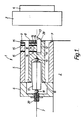
- Figure 1 shows a tool post 1 on a cross slide 2 which is part of a standard lathe (not shown), operated by standard lathe controls.
- the toolpost 1 is shown adjacent a workpiece 3 which is mounted on a spindle 4.
- the spindle 4 is a smooth running spindle since a standard lathe spindle would not be sufficiently smooth for the accuracy required.
- An air bearing would provide a suitable spindle.
- the workpiece 3 may be any material suitable for diamond turning.
- the toolpost 1 has a two-piece metallic housing, i.e. a front housing 5 and a rear housing 6.
- the front housing 5 is of rectangular hollow cross-section and is open at each end. Centre line 7, lies along the axis of the rectangular housing 5.
- front housing 5 The front face of front housing 5 is closed by a first flexible, resilient, metallic plate or diaphragm 8 attached to the front housing 5 by screws 9.
- the front housing 5 and rear housing 6 are arranged so that a second flexible, resilient, metallic plate or diaphragm 10 is fixed between them.
- the plates 8 and 10 are parallel to one another, and are each provided with a hole to allow passage of a part of the arrangement as described below.
- a substantially cylindrical tool carrier 11 Suspended between and supported by the plates 8 and 10, so as not to contact the front housing 5, is a substantially cylindrical tool carrier 11.
- the carrier 11 has mounting means which allows a diamond tool 12 with a single working point 13 to be inserted into the carrier 11 with the point 13 protruding through a hole 28 in the first plate 8.
- the working point 13 is positioned on the centre line 7. Grub screws 14, accessed by holes 15 in the housing 5, hold the tool 12 in place.
- a quadrant photo-diode 16 (hereafter QPD) is mounted in the carrier 11, between the access holes 15.
- QPD quadrant photo-diode 16
- a low power He/Ne laser (not shown) illuminates the QPD 16 through a hole in the front housing 5.
- a piezo-electric element 17 with electrical terminals (not shown) is mounted between a pair of bail bearings 18 and 19 partly within a cylindrical space in the carrier 11.
- the assembly of ball bearings 18 and 19 and piezo-electric element 17 is held in compression by an adjustable screw 20 which is mounted in the rear wall of the housing 6.
- the piezo-electric element 17 passes through a hole in plate 10.
- the adjustable screw 20, the ball bearings 18 and 19, the piezo-electric element 17, and the carrier 11 are all arranged to be co-axial with the centre line 7.
- the position of the diamond tool 12 is controlled by a combination of the standard lathe controls and the piezo-electric element 17.
- the standard lathe controls are used for movements orthogonal to the centre line 7 .
- the operation of the lathe and the piezo-electric element 17 may be monitored and/or controlled by a computer.
- the standard lathe controls are used for movements parallel to the centre line 7 which are greater than about 100 ⁇ m.
- the piezo-electric element 17 is used.
- Application of a voltage, by supply means (not shown), across the terminals of the piezo-electric element 17 causes it to expand and move the carrier 11 forward against the resisting action of plates 8 and 10. In this respect the resistance to the motion of the tool 12 provided by the workpiece 3 is negligible.
- the plates 8 and 10 also serve to prevent movements of the tool 12 orthogonal to the centre line 7 relative to the carrier 11, whilst resiliently allowing movements parallel to the centre line 7.
- the plates 8 and 10 may therefore be replaced by any means adapted to allow only movements parallel with centre line 7 which also provide some resistance to motion of the tool towards the workpiece 3.
- Suitable means include at least three wires in place of each of the plates 8 and 10, or the use of an air bearing around the tool to allow only movements parallel to the centre line 7 together with spring means to provide the necessary resistance. It is to be appreciated that the resistance means must not be mounted in such a way as to allow the workpiece 3 to cause any substantial movement of the tool.
- the rear wall of the housing 6 must be substantially rigid or else this would allow the workpiece 3 to force the tool 12 towards the rear housing 6 thereby substantially reducing the accuracy of the tool control.
- This also requires that the piezo-electric element 17 be rigidly mounted.
- the ball bearings 18 and 19 ensure that the force exerted due to the expansion of the piezo-electric element 17 is transmitted to the carrier 11 substantially along the centre line 7.
- the plates 8 and 10 are capable of elastically deforming over the full range of expansion of the piezo-electric element 17.
- the resistance of the plates 8 and 10 increases the accuracy of the toolpost 1 because voltages applied across the piezo-electric element 17, which would have resulted in large movements of the tool 12, now result in smaller movements.
- the inaccuracy that would normally be associated with the large movement is also scaled down by a similar degree.
- the piezo-electric element 17 thus allows precise adjustment of the tool position over a limited range of about 2 ⁇ m.
- the hysteresis associated with the movement of the piezo-electric element 17 which would lead to inaccuracies is substantially reduced by holding the element 17 in compression between the ball bearings 16 and 18. This allows a resolution of better than 10 nm to be achieved.
- the maximum range could be extended to about 10 ⁇ m, possibly up to about 100 ⁇ m if only soft materials, such as polymers and soft metals, were to be machined.
- the spindle 4 may rotate the workpiece 3 at any angular velocity up to the point where the workpiece 3 shatters on contact with the tool 12. This wide range of angular velocities is highly advantageous since it allows highly detailed surfaces to be machined using this technique. If, for instance, a distinct 'step' is required in the workpiece 3 the angular velocity of the workpiece 3 may be reduced to allow for the time it takes the tool 12 to move the height of the step, thus allowing a substantially accurate step to be produced. Typically the workpiece 3 is rotated from 2000 to 3000 revolutions per minute.
- the output from the QPD 16 may be utilised by the computer controlling the operation when it is necessary to monitor the position of the carrier 11, and thereby the tool point 13, with respect to a datum line.
- the QPD 16 merely provides a convenient method for monitoring the position of the tool 12.
- Other suitable methods include fibre optics probes, strain guages and capacitive micrometers, as will be readily appreciated by one skilled in the art.
- the QPD 16 is advantageous because of its compact size and ease of applicability to the carrier 11.
- the output from the QPD 16 changes when the amount of light falling on it varies.
- the carrier 11 is moved in a direction non-parallel with the direction of the lower beam, the datum line, the output from the QPD 16 is altered and the piezo-electric element 17 may be energised to correct the error.
- Figure 2 shows an infrared binary zone-plate 21 with grooves 22 at precise distances from a centre 23 of the zone plate 21.
- the grooves produce a half wavelength phase difference in the transmitted radiation and so must be of accurate depth.
- a germanium infra-red binary zone-plate was produced by connecting the terminals of the piezo-electric element, through a relay, to a power supply which was set to output a voltage to cause the piezo-electric element to expand to move the tool to produce the depth of cut required.
- the germanium was first faced-off in the usual manner using the standard lathe controls and then, using the facing-off depth as a datum another pass was made to produce the zone-plate.
- the cross slide was connected to a linear transducer, the output from the transducer was fed to a computer which switched the relay (and hence the piezo-electric element) on or off when the computer determined that the transducer output indicated the tool point was at a zone edge.
- the depth of cut was controlled solely by the piezo-electric element.
- the invention is also suitable for manufacturing off axis or irregularly shaped components, and components requiring a varied depth of cut within one rotation.
- Figure 3 shows one such component.
- a 6 mm thick germanium disc 24 of 30 mm diameter has shaded areas 25 raised above an unshaded area 26 by 100 nm (plus or minus 10 nm).
- the relay and power supply referred to above may be replaced by a digital-to-analogue converter.
- a computer monitors the position of the cross slide and the rotation of the spindle. Using this information to determine the precise location of the tool 12 the computer outputs a signal to the digital-to-analogue converter which controls the voltage applied to the piezo-electric element, and thereby the depth of the tool point. In this way blazed or sinusoidal zone plates may also be produced.
- the depth of cut (on which the depth variations are superimposed by the piezo-electric element) can be as large as 50 ⁇ m.
- An alternative method may therefore be employed in which a finished component is produced in one pass by omitting the facing off stage.
- the present invention may also be used to machine a curved workpiece.
- the toolslide substantially follows the surface of the workpiece allowing the piezo-electric element to control the less than 100 ⁇ m movements of the tool perpendicular to the surface of the workpiece.
- the rear housing 6 may be internally threaded to screw onto an externally threaded front housing 5.
- the operations of holding the plate 10 and placing the piezo-electric element 17 in compression may be carried out without adjustable screw 20.
- the plates 8 and 10 may be replaced by any suitable resilient supporting means including using a single plate.
- the piezo-electric element 17 may also be aligned so that it is not co-axial with centre line 7 thus allowing the toolpost 1 to be more compact.
Landscapes
- Engineering & Computer Science (AREA)
- Mechanical Engineering (AREA)
- Machine Tool Units (AREA)
- Turning (AREA)
Abstract
A machine tool for single point diamond turning for use with a workpiece holder which holds and rotates a workpiece, the machine tool comprising a tool carrier arranged for movement towards and away from the workpiece, a rigidly held piezo-electric element to which the tool carrier is operatively coupled and resistance means to resist movement of the tool carrier towards the workpiece, so that when a voltage is applied to the piezo-electric element it expands and moves the tool carrier towards the workpiece against the resistance of the resistance means. The invention also provides a single point diamond turning method in which additional movements of the diamond tool of up to 100 µm are superimosed on movements controlled by conventional lathe controls by applying a voltage across the piezo-electric element.
Description
- This invention concerns improvements in or relating to machine tools for and methods of single point diamond tool turning. The term 'diamond tool' when used herein is to be understood as including, where the context permits, not only natural and synthetic diamond tools but also tools, such as cubic boron nitride tools, which have similar properties to diamond tools.
- It is well known to use diamond tools when machining a wide range of non-metallic materials such as silicon, silicon carbides, glass, copper, aluminium, nickel, germanium, crystalline materials and plastics. Normally the diamond tool is simply used in place of a standard machine tool. However when greater accuracy is required, for instance in machining high quality optical surfaces, a different approach is necessary. In a paper in "Optical Engineering" volume 27,
number 11 at page 1008 in an article entitled "Development of a precision diamond turning machine for fabrication of asymmetric aspheric mirrors", a single point diamond tool fly cutter is controlled by a piezo-actuator. The mechanism disclosed in this paper is designed to machine relatively large mirrors for use in soft x-ray optics. The mechanism achieves an accuracy of 0.1 µm. However for some applications a greater accuracy is required, for instance to produce zone plates. - GB-A-2142860 discloses machine tools wherein a piezo-electric crystal is employed to effect a linear movement to a tool. GB-A-2198669 discloses micro-displacement mechanisms incorporating piezo-electric elements. GB-A-2168272 discloses an accurate positioning apparatus for a machine tool which incorporates mechanical springs.
- A paper entitled "Single-point diamond machining of glasses" by K.E. Puttick et al. in Proc.R.Soc. Lond., A426, 19-30 (1989) was published on 8th November 1989 (i.e. after the filing date of UK Patent Application No. 8912552.0 from which this application claims priority) and discloses a turning machine incorporating a piezo-electric transducer.
- It is an aim of this invention to provide a diamond tool turning apparatus which is capable of machining to an accuracy of better than 0.1 µm. It is a further aim of this invention to provide a method for producing components of accuracy better than 0.1 µm.
- According to one aspect of the present invention there is provided a machine tool for single point diamond turning for use with a workpiece holder which holds and rotates a workpiece, the machine tool comprising a tool carrier arranged for movement towards and away from the workpiece, a rigidly held piezo-electric element to which the tool carrier is operatively coupled and resistance means to resist movement of the tool carrier towards the workpiece, so that when a voltage is applied to the piezo-electric element it expands and moves the tool carrier towards the workpiece against the resistance of the resistance means.
- According to another aspect of the present invention there is provided a single point diamond tool turning method in which a workpiece is rotated by a spindle which is part of a lathe with lathe controls, the method comprising the steps of controlling movements of the diamond tool towards the workpiece by the lathe controls and superimposing additional movements of the diamond tool towards the workpiece of up to 100 µm by applying a voltage across a rigidly held piezo-electric element which expands to move the diamond tool against resistance towards the workpice.
- An embodiment of the invention will now be described, by way of example only, with reference to the following drawings, in which:-
- Figure 1 is a cross-sectional representation of a machine tool according to an embodiment of the present invention;
- Figure 2 is a representation of a zone plate machined using the present invention; and
- Figure 3 is a representation of a workpiece machined using the present invention.
- Figure 1 shows a
tool post 1 on across slide 2 which is part of a standard lathe (not shown), operated by standard lathe controls. Thetoolpost 1 is shown adjacent a workpiece 3 which is mounted on aspindle 4. Thespindle 4 is a smooth running spindle since a standard lathe spindle would not be sufficiently smooth for the accuracy required. An air bearing would provide a suitable spindle. The workpiece 3 may be any material suitable for diamond turning. Thetoolpost 1 has a two-piece metallic housing, i.e. afront housing 5 and arear housing 6. Thefront housing 5 is of rectangular hollow cross-section and is open at each end. Centre line 7, lies along the axis of therectangular housing 5. The front face offront housing 5 is closed by a first flexible, resilient, metallic plate or diaphragm 8 attached to thefront housing 5 by screws 9. Thefront housing 5 andrear housing 6 are arranged so that a second flexible, resilient, metallic plate ordiaphragm 10 is fixed between them. Theplates 8 and 10 are parallel to one another, and are each provided with a hole to allow passage of a part of the arrangement as described below. - Suspended between and supported by the
plates 8 and 10, so as not to contact thefront housing 5, is a substantiallycylindrical tool carrier 11. Thecarrier 11 has mounting means which allows adiamond tool 12 with asingle working point 13 to be inserted into thecarrier 11 with thepoint 13 protruding through ahole 28 in the first plate 8. The workingpoint 13 is positioned on the centre line 7.Grub screws 14, accessed byholes 15 in thehousing 5, hold thetool 12 in place. - A quadrant photo-diode 16 (hereafter QPD) is mounted in the
carrier 11, between theaccess holes 15. A low power He/Ne laser (not shown) illuminates the QPD 16 through a hole in thefront housing 5. - A piezo-
electric element 17 with electrical terminals (not shown) is mounted between a pair ofbail bearings carrier 11. The assembly ofball bearings electric element 17 is held in compression by anadjustable screw 20 which is mounted in the rear wall of thehousing 6. The piezo-electric element 17 passes through a hole inplate 10. Theadjustable screw 20, theball bearings electric element 17, and thecarrier 11 are all arranged to be co-axial with the centre line 7. - In operation the position of the
diamond tool 12 is controlled by a combination of the standard lathe controls and the piezo-electric element 17. For movements orthogonal to the centre line 7 the standard lathe controls are used. The operation of the lathe and the piezo-electric element 17 may be monitored and/or controlled by a computer. The standard lathe controls are used for movements parallel to the centre line 7 which are greater than about 100 µm. For similar movements of less than 100 µm the piezo-electric element 17 is used. Application of a voltage, by supply means (not shown), across the terminals of the piezo-electric element 17 causes it to expand and move thecarrier 11 forward against the resisting action ofplates 8 and 10. In this respect the resistance to the motion of thetool 12 provided by the workpiece 3 is negligible. Theplates 8 and 10 also serve to prevent movements of thetool 12 orthogonal to the centre line 7 relative to thecarrier 11, whilst resiliently allowing movements parallel to the centre line 7. Theplates 8 and 10 may therefore be replaced by any means adapted to allow only movements parallel with centre line 7 which also provide some resistance to motion of the tool towards the workpiece 3. Suitable means include at least three wires in place of each of theplates 8 and 10, or the use of an air bearing around the tool to allow only movements parallel to the centre line 7 together with spring means to provide the necessary resistance. It is to be appreciated that the resistance means must not be mounted in such a way as to allow the workpiece 3 to cause any substantial movement of the tool. For instance in the specific embodiment described above the rear wall of thehousing 6 must be substantially rigid or else this would allow the workpiece 3 to force thetool 12 towards therear housing 6 thereby substantially reducing the accuracy of the tool control. This also requires that the piezo-electric element 17 be rigidly mounted. - The
ball bearings electric element 17 is transmitted to thecarrier 11 substantially along the centre line 7. Theplates 8 and 10 are capable of elastically deforming over the full range of expansion of the piezo-electric element 17. The resistance of theplates 8 and 10 increases the accuracy of thetoolpost 1 because voltages applied across the piezo-electric element 17, which would have resulted in large movements of thetool 12, now result in smaller movements. The inaccuracy that would normally be associated with the large movement is also scaled down by a similar degree. - The piezo-
electric element 17 thus allows precise adjustment of the tool position over a limited range of about 2 µm. The hysteresis associated with the movement of the piezo-electric element 17 which would lead to inaccuracies is substantially reduced by holding theelement 17 in compression between theball bearings 16 and 18. This allows a resolution of better than 10 nm to be achieved. The maximum range could be extended to about 10 µm, possibly up to about 100 µm if only soft materials, such as polymers and soft metals, were to be machined. - The
spindle 4 may rotate the workpiece 3 at any angular velocity up to the point where the workpiece 3 shatters on contact with thetool 12. This wide range of angular velocities is highly advantageous since it allows highly detailed surfaces to be machined using this technique. If, for instance, a distinct 'step' is required in the workpiece 3 the angular velocity of the workpiece 3 may be reduced to allow for the time it takes thetool 12 to move the height of the step, thus allowing a substantially accurate step to be produced. Typically the workpiece 3 is rotated from 2000 to 3000 revolutions per minute. - The output from the QPD 16 may be utilised by the computer controlling the operation when it is necessary to monitor the position of the
carrier 11, and thereby thetool point 13, with respect to a datum line. The QPD 16 merely provides a convenient method for monitoring the position of thetool 12. Other suitable methods include fibre optics probes, strain guages and capacitive micrometers, as will be readily appreciated by one skilled in the art. The QPD 16 is advantageous because of its compact size and ease of applicability to thecarrier 11. - The output from the QPD 16 changes when the amount of light falling on it varies. Thus if the
carrier 11 is moved in a direction non-parallel with the direction of the lower beam, the datum line, the output from the QPD 16 is altered and the piezo-electric element 17 may be energised to correct the error. - This invention allows a variety of components to be produced. Figure 2 shows an infrared binary zone-
plate 21 withgrooves 22 at precise distances from acentre 23 of thezone plate 21. The grooves produce a half wavelength phase difference in the transmitted radiation and so must be of accurate depth. A germanium infra-red binary zone-plate was produced by connecting the terminals of the piezo-electric element, through a relay, to a power supply which was set to output a voltage to cause the piezo-electric element to expand to move the tool to produce the depth of cut required. The germanium was first faced-off in the usual manner using the standard lathe controls and then, using the facing-off depth as a datum another pass was made to produce the zone-plate. The cross slide was connected to a linear transducer, the output from the transducer was fed to a computer which switched the relay (and hence the piezo-electric element) on or off when the computer determined that the transducer output indicated the tool point was at a zone edge. The depth of cut was controlled solely by the piezo-electric element. - The invention is also suitable for manufacturing off axis or irregularly shaped components, and components requiring a varied depth of cut within one rotation. Figure 3 shows one such component. A 6 mm
thick germanium disc 24 of 30 mm diameter has shadedareas 25 raised above anunshaded area 26 by 100 nm (plus or minus 10 nm). - The relay and power supply referred to above may be replaced by a digital-to-analogue converter. A computer monitors the position of the cross slide and the rotation of the spindle. Using this information to determine the precise location of the
tool 12 the computer outputs a signal to the digital-to-analogue converter which controls the voltage applied to the piezo-electric element, and thereby the depth of the tool point. In this way blazed or sinusoidal zone plates may also be produced. - When soft materials are being machined the depth of cut (on which the depth variations are superimposed by the piezo-electric element) can be as large as 50 µm. An alternative method may therefore be employed in which a finished component is produced in one pass by omitting the facing off stage.
- The present invention may also be used to machine a curved workpiece. In this case the toolslide substantially follows the surface of the workpiece allowing the piezo-electric element to control the less than 100 µm movements of the tool perpendicular to the surface of the workpiece.
- A number of alternative constructions are possible. For instance the
rear housing 6 may be internally threaded to screw onto an externally threadedfront housing 5. Thus the operations of holding theplate 10 and placing the piezo-electric element 17 in compression may be carried out withoutadjustable screw 20. Further theplates 8 and 10 may be replaced by any suitable resilient supporting means including using a single plate. The piezo-electric element 17 may also be aligned so that it is not co-axial with centre line 7 thus allowing thetoolpost 1 to be more compact.
Claims (10)
1. A machine tool for single point diamond turning for use with a workpiece holder (4) which holds and rotates a workpiece (3), the machine tool comprising a tool carrier (11) arranged for movement towards and away from the workpiece (3), a rigidly held piezo-electric element (17) to which the tool carrier (11) is operatively coupled and resistance means (8,10) to resist movement of the tool carrier (11) towards the workpiece (3), so that when a voltage is applied to the piezo-electric element (17) it expands and moves the tool carrier (11) towards the workpiece (3) against the resistance of the resistance means (8,10).
2. A machine tool according to claim 1 in which the resistance means (8,10) comprises at least one resilient plate which engages the tool carrier (11).
3. A machine tool according to claim 2 in which the resistance means (8,10) comprises a pair of the resilient plates mounted at opposed ends of the tool carrier (11).
4. A machine tool according to any one of claims 1 to 3 in which the direction of expansion of the piezo-electric element (17) is parallel with the axis of rotation of the workpiece holder (4).
5. A machine tool according to any preceding claim further comprising means, including a quadrant photo-diode (16), for indicating the position of a tool (12) which is carried by the tool carrier (11).
6. A machine tool according to any preceding claim further comprising means (18,19,20) for holding the piezo-electric element (17) in compression.
7. A single point diamond tool turning method in which a workpiece (3) is rotated by a spindle which is part of a lathe with lathe controls, the method comprising the steps of controlling movements of the diamond tool (12) towards the workpiece by the lathe controls and superimposing additional movements of the diamond tool (12) towards the workpiece (3) of up to 100 µm by applying a voltage across a rigidly held piezo-electric element (17) which expands to move the diamond tool (12) against resistance towards the workpice (3).
8. A method according to claim 7 wherein the additional movements superimposed by the piezo-electric element (17) are up to 10 µm.
9. A method according to claim 8 wherein the additional movements superimposed by the piezo-electric element (17) are up to 2 µm.
10. A method according to any one of claims 7 to 9 in which the piezo-electric element (17) expands in a direction substantially parallel with the axis of rotation of the workpiece (3).
Applications Claiming Priority (2)
| Application Number | Priority Date | Filing Date | Title |
|---|---|---|---|
| GB898912552A GB8912552D0 (en) | 1989-06-01 | 1989-06-01 | Machine tool for single point diamond turning |
| GB8912552 | 1989-06-01 |
Publications (2)
| Publication Number | Publication Date |
|---|---|
| EP0402011A2 true EP0402011A2 (en) | 1990-12-12 |
| EP0402011A3 EP0402011A3 (en) | 1992-12-02 |
Family
ID=10657683
Family Applications (1)
| Application Number | Title | Priority Date | Filing Date |
|---|---|---|---|
| EP19900305673 Withdrawn EP0402011A3 (en) | 1989-06-01 | 1990-05-24 | Machine tool for and method of single point diamond turning |
Country Status (3)
| Country | Link |
|---|---|
| EP (1) | EP0402011A3 (en) |
| JP (1) | JPH0349843A (en) |
| GB (1) | GB8912552D0 (en) |
Cited By (8)
| Publication number | Priority date | Publication date | Assignee | Title |
|---|---|---|---|---|
| WO2005108004A1 (en) * | 2004-04-23 | 2005-11-17 | Schott Ag | Device and method for the production of microstructures |
| WO2007028532A3 (en) * | 2005-09-08 | 2007-07-05 | Schott Ag | Actuator for displacing a tool |
| CN100592959C (en) * | 2004-04-23 | 2010-03-03 | 肖特股份公司 | Device and actuator for forming microstructures |
| JP2013168221A (en) * | 2012-02-14 | 2013-08-29 | Gigaphoton Inc | Target supply device |
| CN103831654A (en) * | 2014-03-05 | 2014-06-04 | 常州市宏达机床数控设备有限公司 | Signaling disc for electrical tool carrier |
| CN103831655A (en) * | 2014-03-05 | 2014-06-04 | 常州市宏达机床数控设备有限公司 | Signal sending disk with answer signals for electric tool rest |
| CN103831656A (en) * | 2014-03-05 | 2014-06-04 | 常州市宏达机床数控设备有限公司 | Signaling disc for electric tool rest |
| EP2812153B1 (en) * | 2012-02-06 | 2017-12-27 | Schneider GmbH & Co. KG | Linear drive |
Families Citing this family (2)
| Publication number | Priority date | Publication date | Assignee | Title |
|---|---|---|---|---|
| CN103170661B (en) * | 2013-03-29 | 2016-04-13 | 浙江大学宁波理工学院 | Medium scale part minuteness milling lathe |
| CN110814432B (en) * | 2019-11-13 | 2021-05-04 | 中国工程物理研究院机械制造工艺研究所 | Ultra-precise fly-cutting machining method for micron-scale steps |
Family Cites Families (3)
| Publication number | Priority date | Publication date | Assignee | Title |
|---|---|---|---|---|
| GB1472066A (en) * | 1974-06-26 | 1977-04-27 | British Aircraft Corp Ltd | Photoelectric apparatus |
| DE8513146U1 (en) * | 1985-05-04 | 1988-04-28 | Alfing Kessler Sondermaschinen GmbH, 7080 Aalen | Rotating device |
| JPH01264757A (en) * | 1988-04-18 | 1989-10-23 | Hitachi Ltd | Polishing method for rotationally symmetric aspherical surfaces |
-
1989
- 1989-06-01 GB GB898912552A patent/GB8912552D0/en active Pending
-
1990
- 1990-05-24 EP EP19900305673 patent/EP0402011A3/en not_active Withdrawn
- 1990-06-01 JP JP14169590A patent/JPH0349843A/en active Pending
Cited By (14)
| Publication number | Priority date | Publication date | Assignee | Title |
|---|---|---|---|---|
| CN100592959C (en) * | 2004-04-23 | 2010-03-03 | 肖特股份公司 | Device and actuator for forming microstructures |
| US7823488B2 (en) | 2004-04-23 | 2010-11-02 | Schott Ag | Device for producing microstructures |
| US7480540B2 (en) | 2004-04-23 | 2009-01-20 | Schott Ag | Method for producing microstructures |
| WO2005108004A1 (en) * | 2004-04-23 | 2005-11-17 | Schott Ag | Device and method for the production of microstructures |
| US7545078B2 (en) | 2005-09-08 | 2009-06-09 | Schott Ag | Actuator for moving a tool |
| CN101198439B (en) * | 2005-09-08 | 2010-09-22 | 肖特股份公司 | Actuators for moving tools and devices for processing workpieces |
| WO2007028532A3 (en) * | 2005-09-08 | 2007-07-05 | Schott Ag | Actuator for displacing a tool |
| EP2812153B1 (en) * | 2012-02-06 | 2017-12-27 | Schneider GmbH & Co. KG | Linear drive |
| JP2013168221A (en) * | 2012-02-14 | 2013-08-29 | Gigaphoton Inc | Target supply device |
| CN103831654A (en) * | 2014-03-05 | 2014-06-04 | 常州市宏达机床数控设备有限公司 | Signaling disc for electrical tool carrier |
| CN103831655A (en) * | 2014-03-05 | 2014-06-04 | 常州市宏达机床数控设备有限公司 | Signal sending disk with answer signals for electric tool rest |
| CN103831656A (en) * | 2014-03-05 | 2014-06-04 | 常州市宏达机床数控设备有限公司 | Signaling disc for electric tool rest |
| CN103831655B (en) * | 2014-03-05 | 2016-06-15 | 江苏宏达数控科技股份有限公司 | Electric driving tool post sender set with recall signal |
| CN103831656B (en) * | 2014-03-05 | 2017-02-08 | 江苏宏达数控科技股份有限公司 | Sending disc for electric knife holder |
Also Published As
| Publication number | Publication date |
|---|---|
| EP0402011A3 (en) | 1992-12-02 |
| JPH0349843A (en) | 1991-03-04 |
| GB8912552D0 (en) | 1989-07-19 |
Similar Documents
| Publication | Publication Date | Title |
|---|---|---|
| US5802937A (en) | Smart tool holder | |
| Okazaki | A micro-positioning tool post using a piezoelectric actuator for diamond turning machines | |
| US4581808A (en) | Adjustable machining system and implement therefore | |
| EP1275036B1 (en) | Abbe error correction system and method | |
| EP0402011A2 (en) | Machine tool for and method of single point diamond turning | |
| JP2001526967A (en) | Workpiece processing equipment | |
| JP2972207B2 (en) | Rotary cutting tool and apparatus having the rotary cutting tool in combination with a machine tool | |
| HK100695A (en) | Device for machining an ophthalmic lens with, in particular, aspheric surfaces | |
| Kohno et al. | In-process measurement and a workpiece-referred form accuracy control system (WORFAC): concept of the method and preliminary experiment | |
| Altintas et al. | A piezo tool actuator for precision turning of hardened shafts | |
| EP0376965A1 (en) | Apparatus and methods for automatically determining the radius described by a tool tip mounted for a rotary machining operation | |
| JP2000512566A (en) | Electric / mechanical actuator | |
| JP2000033502A (en) | Lathe device and tool height alignment method | |
| US5393177A (en) | Tool wear compensation system | |
| JPS6247657B2 (en) | ||
| JP3333679B2 (en) | Groove cutting device and groove cutting method | |
| EP0454254A1 (en) | Positioning device having static fluid bearings | |
| Benjamin | Diamond turning at a large optical manufacturer | |
| Falter et al. | Design and performance of a small—scale diamond turning machine | |
| CN85105481A (en) | The reference data of cutter contact detection system | |
| Kim et al. | Development and application of an ultra-precision lathe | |
| Ljubarsky et al. | Optical surface fabrication on ultra precision machines | |
| Moriyama et al. | Development of a Precision Diamond Cutting Machine for Fabrication of Asymmetrical Aspheric Mirrors | |
| JPS62208839A (en) | Machine tool conducting cutting work | |
| Brehm et al. | Low thermal expansion materials for high precision measurement equipment |
Legal Events
| Date | Code | Title | Description |
|---|---|---|---|
| PUAI | Public reference made under article 153(3) epc to a published international application that has entered the european phase |
Free format text: ORIGINAL CODE: 0009012 |
|
| AK | Designated contracting states |
Kind code of ref document: A2 Designated state(s): DE FR GB IT NL |
|
| PUAL | Search report despatched |
Free format text: ORIGINAL CODE: 0009013 |
|
| AK | Designated contracting states |
Kind code of ref document: A3 Designated state(s): DE FR GB IT NL |
|
| STAA | Information on the status of an ep patent application or granted ep patent |
Free format text: STATUS: THE APPLICATION IS DEEMED TO BE WITHDRAWN |
|
| 18D | Application deemed to be withdrawn |
Effective date: 19921201 |