EP0401732B1 - A device for steering the rear wheels of a motor vehicle - Google Patents
A device for steering the rear wheels of a motor vehicle Download PDFInfo
- Publication number
- EP0401732B1 EP0401732B1 EP90110578A EP90110578A EP0401732B1 EP 0401732 B1 EP0401732 B1 EP 0401732B1 EP 90110578 A EP90110578 A EP 90110578A EP 90110578 A EP90110578 A EP 90110578A EP 0401732 B1 EP0401732 B1 EP 0401732B1
- Authority
- EP
- European Patent Office
- Prior art keywords
- steering
- rear wheels
- connection means
- control
- support member
- Prior art date
- Legal status (The legal status is an assumption and is not a legal conclusion. Google has not performed a legal analysis and makes no representation as to the accuracy of the status listed.)
- Expired - Lifetime
Links
- 230000008878 coupling Effects 0.000 claims description 3
- 238000010168 coupling process Methods 0.000 claims description 3
- 238000005859 coupling reaction Methods 0.000 claims description 3
- 230000007935 neutral effect Effects 0.000 claims 2
- 230000004913 activation Effects 0.000 claims 1
Images


Classifications
-
- B—PERFORMING OPERATIONS; TRANSPORTING
- B62—LAND VEHICLES FOR TRAVELLING OTHERWISE THAN ON RAILS
- B62D—MOTOR VEHICLES; TRAILERS
- B62D7/00—Steering linkage; Stub axles or their mountings
- B62D7/06—Steering linkage; Stub axles or their mountings for individually-pivoted wheels, e.g. on king-pins
- B62D7/14—Steering linkage; Stub axles or their mountings for individually-pivoted wheels, e.g. on king-pins the pivotal axes being situated in more than one plane transverse to the longitudinal centre line of the vehicle, e.g. all-wheel steering
- B62D7/15—Steering linkage; Stub axles or their mountings for individually-pivoted wheels, e.g. on king-pins the pivotal axes being situated in more than one plane transverse to the longitudinal centre line of the vehicle, e.g. all-wheel steering characterised by means varying the ratio between the steering angles of the steered wheels
- B62D7/1518—Steering linkage; Stub axles or their mountings for individually-pivoted wheels, e.g. on king-pins the pivotal axes being situated in more than one plane transverse to the longitudinal centre line of the vehicle, e.g. all-wheel steering characterised by means varying the ratio between the steering angles of the steered wheels comprising a mechanical interconnecting system between the steering control means of the different axles
- B62D7/1545—Steering linkage; Stub axles or their mountings for individually-pivoted wheels, e.g. on king-pins the pivotal axes being situated in more than one plane transverse to the longitudinal centre line of the vehicle, e.g. all-wheel steering characterised by means varying the ratio between the steering angles of the steered wheels comprising a mechanical interconnecting system between the steering control means of the different axles provided with electrical assistance
Definitions
- the present invention relates to a device for steering the rear wheels of a motor vehicle as described in the precharacterising part of the appended main claim.
- a device of this type is described, for example, in EP-A-0 278 439, wherein the means for varying the ratio between the steering angle of the front wheels and that of the rear wheels is a complex mechanism formed by a plurality of different elements.
- the object of the present invention is to provide a device of the type indicated above whereby the ratio between the steering angle of the front wheels and that of the rear wheels can be varied simply and reliably according to the speed of the vehicle.
- the device to steer the front and rear wheels in opposite directions at low speeds and in the same direction at high speeds, appreciably improving the manoeuvrability and stability of the vehicle.
- the steering wheel 1 is connected to the front wheels 2 by means of a kinematic steering chain of known type, not shown.
- An electrical or hydraulic actuator mechanism 5, also of known type, is situated in correspondence with the axle of the rear wheels 4 and is driven by an hydraulic or electrical servo-control 6 to steer the rear wheels 4.
- the kinematic steering chain is connected to the servo-control 6 by means of a flexible cable 8 for transmitting the steering movement to the rear wheels 4.
- the cable 8 can be positioned in the free spaces in the motor-vehicle body.
- the cable 8 ( Figure 2) is formed by a flexible tubular sheath 10 which houses a flexible, movable blade 12 which constitutes the movement-transmission member and has an end attachment 13 engaged with the kinematic steering chain.
- the blade 12 has rounded seats 14 in its main face which enable it to slide relative to two juxtaposed series of balls 16.
- the balls 16 of each series are held apart by respective strips 18 and can in turn run in rounded grooves 20 formed in profiled elements 22.
- the cable 8 is fixed ( Figure 3) by means of U-bolt-shaped fixing elements 23 to a support member 24 and has a projecting pin 26 connected to the movable blade 12.
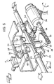
- a shaft 28 is connected rigidly to the support member 24 and carries a toothed sector 30 which meshes with a threaded shaft 32 rotatable by a stepped motor 34 in dependence on the speed of the motor vehicle.
- the support member 24 can thus rotate about an axis perpendicular to its own general plane.
- the servo-control 6, in the embodiment illustrated, comprises a hydraulic valve 36, but could alternatively be an equivalent electrical system, and is provided with a movable member 38 to which is fixed a guide element 40 defining a slot-like aperture 42 which is substantially parallel to the line of the end part of the cable 8 when the rotation of the support member 24 is zero ( Figure 4).
- the end 44 of the pin 26 fixed to the movable blade 12 of the flexible cable 8 is constrained but movable in the slot-like aperture 42.
- the operation of the device is governed by a combination of the rotary movements of the support member 24 and the translational movements of the pin 26 in the slot-like aperture 42.
- the stepped motor 34 rotates the support member 24 and the end part of the cable 8 fixed thereto through an angle 46 which depends, according to a desired relationship, on the speed of the motor vehicle.
- the magnitude of the movement of the movable member 38 depends on the angle 46 between the direction of the slot-like aperture 42 and that of the end part of the cable 8 as a result of the rotation of the support member 24.
- the device can obviously be adjusted so that, for any speed of the motor vehicle, the servo-control 6 achieves an optional ratio between the steering angle of the rear wheels 4 and that of the front wheels 2.
- Figure 6 shows an alternative embodiment of the means for connecting the kinematic steering chain to the servo-control 6.
- parts which are the same as or equivalent to those described above are indicated by the same reference numerals as were used previously.
- a rack rod 48 which supports the pin 26 is fixed to the member 24 by means of the U-bolts 23 so as to be slidable along the line identified by its axis.
- a gear 50 meshes with the rack rod 48 and is connected by means of a ball coupling 52 to a shaft 54 whose rotation is governed, in known manner not illustrated, by the kinematic steering chain. The rotation of the shaft 54 thus causes a translational movement of the rod 48 and a corresponding movement of the end 44 of the pin 26 in the slot-like aperture 42.
- the support member 24 is rotated by the motor 34 in a manner similar to that in the previous case.
- the ball coupling 52 enables a connection to be maintained under all operating conditions between the gear 50 which is driven by the rack 48 during the rotation of the member 24 and the shaft 54 which rotates about its own axis but is not affected by the rotary motion of the member 24.
Landscapes
- Engineering & Computer Science (AREA)
- Chemical & Material Sciences (AREA)
- Combustion & Propulsion (AREA)
- Transportation (AREA)
- Mechanical Engineering (AREA)
- Steering-Linkage Mechanisms And Four-Wheel Steering (AREA)
Description
- The present invention relates to a device for steering the rear wheels of a motor vehicle as described in the precharacterising part of the appended main claim.
- A device of this type is described, for example, in EP-A-0 278 439, wherein the means for varying the ratio between the steering angle of the front wheels and that of the rear wheels is a complex mechanism formed by a plurality of different elements.
- The object of the present invention is to provide a device of the type indicated above whereby the ratio between the steering angle of the front wheels and that of the rear wheels can be varied simply and reliably according to the speed of the vehicle.
- This object is achieved by a device of the type indicated above having the characteristics given in the characterising part of the appended main claim.
- In particular, it is convenient for the device to steer the front and rear wheels in opposite directions at low speeds and in the same direction at high speeds, appreciably improving the manoeuvrability and stability of the vehicle.
- Advantages and characteristics of the present invention will become clear from the following detailed description given with reference to the appended drawings, provided purely by way of non-limiting example, in which:
- Figure 1 is a schematic view of some details of a motor vehicle provided with a device according to the present invention,
- Figure 2 is a cut-away perspective view of a flexible cable used in the device according to the invention,
- Figure 3 is a schematic perspective view of the mechanism which enables the ratio between the steering angle of the front wheels and that of the rear wheels to be varied according to the speed of the vehicle,
- Figures 4 and 5 are schematic plan views of the detail shown in Figure 3 in two different operating conditions, and
- Figure 6 is a schematic perspective view of an alternative embodiment of the mechanism of Figure 3.
- In a motor vehicle (Figure 1), the steering wheel 1 is connected to the front wheels 2 by means of a kinematic steering chain of known type, not shown. An electrical or
hydraulic actuator mechanism 5, also of known type, is situated in correspondence with the axle of therear wheels 4 and is driven by an hydraulic or electrical servo-control 6 to steer therear wheels 4. The kinematic steering chain is connected to the servo-control 6 by means of aflexible cable 8 for transmitting the steering movement to therear wheels 4. By virtue of its flexibility, thecable 8 can be positioned in the free spaces in the motor-vehicle body. - The cable 8 (Figure 2) is formed by a flexible
tubular sheath 10 which houses a flexible,movable blade 12 which constitutes the movement-transmission member and has anend attachment 13 engaged with the kinematic steering chain. Theblade 12 has roundedseats 14 in its main face which enable it to slide relative to two juxtaposed series ofballs 16. Theballs 16 of each series are held apart byrespective strips 18 and can in turn run inrounded grooves 20 formed in profiledelements 22. - Near the
actuator element 6, thecable 8 is fixed (Figure 3) by means of U-bolt-shaped fixing elements 23 to asupport member 24 and has a projectingpin 26 connected to themovable blade 12. Ashaft 28 is connected rigidly to thesupport member 24 and carries atoothed sector 30 which meshes with a threadedshaft 32 rotatable by astepped motor 34 in dependence on the speed of the motor vehicle. Thesupport member 24 can thus rotate about an axis perpendicular to its own general plane. - The servo-
control 6, in the embodiment illustrated, comprises ahydraulic valve 36, but could alternatively be an equivalent electrical system, and is provided with amovable member 38 to which is fixed aguide element 40 defining a slot-like aperture 42 which is substantially parallel to the line of the end part of thecable 8 when the rotation of thesupport member 24 is zero (Figure 4). Theend 44 of thepin 26 fixed to themovable blade 12 of theflexible cable 8 is constrained but movable in the slot-like aperture 42. - The operation of the device is governed by a combination of the rotary movements of the
support member 24 and the translational movements of thepin 26 in the slot-like aperture 42. Thestepped motor 34 rotates thesupport member 24 and the end part of thecable 8 fixed thereto through anangle 46 which depends, according to a desired relationship, on the speed of the motor vehicle. Hence, when the steering movement of the front wheels 2 is transmitted along thecable 8 and causes the translation of theblade 12 and of thepin 26, the latter slides in the slot-like aperture 42 and moves themovable member 38 so as to operate thevalve 36 of the servo-control 6 which activates theactuator 5 and consequently steers the rear wheels 4 (Figure 5). - The magnitude of the movement of the
movable member 38 depends on theangle 46 between the direction of the slot-like aperture 42 and that of the end part of thecable 8 as a result of the rotation of thesupport member 24. The device can obviously be adjusted so that, for any speed of the motor vehicle, the servo-control 6 achieves an optional ratio between the steering angle of therear wheels 4 and that of the front wheels 2. - Figure 6 shows an alternative embodiment of the means for connecting the kinematic steering chain to the servo-
control 6. In this drawing, parts which are the same as or equivalent to those described above are indicated by the same reference numerals as were used previously. - A
rack rod 48 which supports thepin 26 is fixed to themember 24 by means of theU-bolts 23 so as to be slidable along the line identified by its axis. Agear 50 meshes with therack rod 48 and is connected by means of aball coupling 52 to ashaft 54 whose rotation is governed, in known manner not illustrated, by the kinematic steering chain. The rotation of theshaft 54 thus causes a translational movement of therod 48 and a corresponding movement of theend 44 of thepin 26 in the slot-like aperture 42. - The
support member 24 is rotated by themotor 34 in a manner similar to that in the previous case. - The
ball coupling 52 enables a connection to be maintained under all operating conditions between thegear 50 which is driven by therack 48 during the rotation of themember 24 and theshaft 54 which rotates about its own axis but is not affected by the rotary motion of themember 24.
Claims (5)
- A device for steering the rear wheels (4) of a motor vehicle, comprising:- a kinematic steering chain for transmitting the steering movement from the steering wheel (1) to the front wheels (2),- a servo-control (6) which steers the rear wheels (4) through an actuator mechanism (5) said servo-control (6) comprising a control member (38), which is slidable along a first axis, and- connection means for transmitting the movement between the kinematic steering chain and the servo-control (6) in order to steer the rear wheels (4) as a result of the steering of the front wheels (2) said connection means comprising means for varying the ratio between the steering angle of the front wheels (2) and that of the rear wheels (4) according to the speed of the vehicle,
the device being characterised in that the means for varying the ratio between the steering angle of the front wheels (2) and that of the rear wheels (4) according to the speed of the vehicle comprise:- a member (24) which supports the end portion of the connection means, said end portion consisting of a guided member, which can slide along a second axis, which is perpendicular to the first axis, when the support member (24) is in a neutral position corresponding to a condition in which the rear wheels (4) are not steerable, and the support member (24) having means which cause it to rotate about a third axis substantially perpendicular to and intersecting the first axis, the magnitude of the rotation depending on the speed of the motor vehicle, and- a guide element (40) connected rigidly to the control member (38) of the servo-control (6) and defining a slot-like aperture (42) which is substantially parallel to the second axis when the support member (24) is in its neutral position, a pin (26) being fixed to the end portion of the connection means and constrained for movement in the aperture, the movement of the pin (26) in the aperture (42) due to the steering of the front wheels (2) driving a translational movement of the control member (38) the magnitude of which depends on the angle (46) between the slot-like aperture (42) and the end portion of the connection means (8) resulting from the rotation of the support member (24), and the translation causing a corresponding activation of the servo-control(6)and hence of the actuator mechanism (5), with a predetermined steering of the rear wheels (4). - A device according to Claim 1, characterised in that the means for rotating the support member (24) comprise a stepped motor (34) driven in dependence on the speed of the motor vehicle and driving a threaded shaft (32) which meshes with a toothed sector (30) fixed to the support member (24).
- A device according to Claim 1 or Claim 2, characterised in that the connection means comprise a flexible cable (8).
- A device according to Claim 1 or Claim 2, characterised in that the connection means include a rack rod (48) which constitutes the end portion of the connection means and a gear (50) wich meshes with the rack (48) and is driven by a rotary shaft (54).
- A device according to Claim 4, characterised in that the gear wheel (50) is connected to the rotary shaft (54) by means of a ball coupling (52).
Applications Claiming Priority (2)
| Application Number | Priority Date | Filing Date | Title |
|---|---|---|---|
| IT6745489 | 1989-06-07 | ||
| IT8967454A IT1234797B (en) | 1989-06-07 | 1989-06-07 | DEVICE FOR THE CONTROL OF STEERING THE REAR WHEELS OF A VEHICLE |
Publications (2)
| Publication Number | Publication Date |
|---|---|
| EP0401732A1 EP0401732A1 (en) | 1990-12-12 |
| EP0401732B1 true EP0401732B1 (en) | 1993-12-29 |
Family
ID=11302517
Family Applications (1)
| Application Number | Title | Priority Date | Filing Date |
|---|---|---|---|
| EP90110578A Expired - Lifetime EP0401732B1 (en) | 1989-06-07 | 1990-06-05 | A device for steering the rear wheels of a motor vehicle |
Country Status (4)
| Country | Link |
|---|---|
| EP (1) | EP0401732B1 (en) |
| DE (1) | DE69005532T2 (en) |
| ES (1) | ES2047760T3 (en) |
| IT (1) | IT1234797B (en) |
Citations (1)
| Publication number | Priority date | Publication date | Assignee | Title |
|---|---|---|---|---|
| EP0278439A2 (en) * | 1987-02-06 | 1988-08-17 | Mazda Motor Corporation | Method of and apparatus for checking four-wheel steering characteristics of four-wheel-steered vehicle |
Family Cites Families (3)
| Publication number | Priority date | Publication date | Assignee | Title |
|---|---|---|---|---|
| US4505491A (en) * | 1982-03-25 | 1985-03-19 | Honda Giken Kogyo Kabushiki Kaisha | Steering system for vehicles |
| JPS628869A (en) * | 1985-07-08 | 1987-01-16 | Mazda Motor Corp | Four wheel steering device for vehicle |
| WO1989004269A1 (en) * | 1987-11-04 | 1989-05-18 | Zahnradfabrik Friedrichshafen Ag | Steering device for steerable front and rear wheels of vehicles |
-
1989
- 1989-06-07 IT IT8967454A patent/IT1234797B/en active
-
1990
- 1990-06-05 DE DE90110578T patent/DE69005532T2/en not_active Expired - Fee Related
- 1990-06-05 ES ES90110578T patent/ES2047760T3/en not_active Expired - Lifetime
- 1990-06-05 EP EP90110578A patent/EP0401732B1/en not_active Expired - Lifetime
Patent Citations (1)
| Publication number | Priority date | Publication date | Assignee | Title |
|---|---|---|---|---|
| EP0278439A2 (en) * | 1987-02-06 | 1988-08-17 | Mazda Motor Corporation | Method of and apparatus for checking four-wheel steering characteristics of four-wheel-steered vehicle |
Also Published As
| Publication number | Publication date |
|---|---|
| ES2047760T3 (en) | 1994-03-01 |
| IT8967454A0 (en) | 1989-06-07 |
| EP0401732A1 (en) | 1990-12-12 |
| IT1234797B (en) | 1992-05-27 |
| DE69005532T2 (en) | 1994-04-28 |
| DE69005532D1 (en) | 1994-02-10 |
Similar Documents
| Publication | Publication Date | Title |
|---|---|---|
| US5002142A (en) | Vehicle steering system | |
| US5131483A (en) | Single lever control | |
| CA1184507A (en) | Control mechanism for a dual hydrostatic transmission vehicle drive system | |
| SU1362396A3 (en) | Manipulator head | |
| US3903983A (en) | Steering system for vehicles | |
| EP0101579B1 (en) | Steering gear | |
| US5409079A (en) | Independently movable control console for tractors | |
| US3891042A (en) | Control arrangement for a hydraulically powered vehicle | |
| GB2107279A (en) | Improvements relating to robot manipulators | |
| US4373603A (en) | Automatic crab steering | |
| US4934208A (en) | Vehicle transmission shifter | |
| US5409080A (en) | Shiftable control console for tractors | |
| US4418633A (en) | Apparatus for controlling a watercraft | |
| EP0204305B1 (en) | Four-wheel steering system for automotive vehicles | |
| GB2188600A (en) | Steering system for front and rear wheels of automotive vehicle | |
| US4652004A (en) | Steer guiding device | |
| EP0401732A1 (en) | A device for steering the rear wheels of a motor vehicle | |
| CA1266442A (en) | Actuator for steering the rear wheels in front and rear wheel steering device for vehicle | |
| US4874183A (en) | Four-wheel steering apparatus of a vehicle | |
| US4947948A (en) | Control device for differential speed steering of a vehicle | |
| ATE104753T1 (en) | HYDRAULIC ACTUATOR INTENDED FOR CONTROLLING THE GEAR SELECTION AND GEAR SHIFT OPERATIONS OF A MECHANICAL TRANSMISSION FOR MOTOR VEHICLES. | |
| EP3693250B1 (en) | Selectively reconfigurable drive-assembly | |
| US3982603A (en) | Steering systems for guided vehicles | |
| EP0925963A1 (en) | Towing device for coupling a towed vehicle to a towing vehicle comprising a trailer steering device | |
| CN216734470U (en) | Vehicle steering device, steering system and vehicle thereof |
Legal Events
| Date | Code | Title | Description |
|---|---|---|---|
| PUAI | Public reference made under article 153(3) epc to a published international application that has entered the european phase |
Free format text: ORIGINAL CODE: 0009012 |
|
| AK | Designated contracting states |
Kind code of ref document: A1 Designated state(s): DE ES FR GB IT SE |
|
| 17P | Request for examination filed |
Effective date: 19901129 |
|
| 17Q | First examination report despatched |
Effective date: 19920918 |
|
| GRAA | (expected) grant |
Free format text: ORIGINAL CODE: 0009210 |
|
| AK | Designated contracting states |
Kind code of ref document: B1 Designated state(s): DE ES FR GB IT SE |
|
| ITF | It: translation for a ep patent filed | ||
| REF | Corresponds to: |
Ref document number: 69005532 Country of ref document: DE Date of ref document: 19940210 |
|
| REG | Reference to a national code |
Ref country code: ES Ref legal event code: FG2A Ref document number: 2047760 Country of ref document: ES Kind code of ref document: T3 |
|
| ET | Fr: translation filed | ||
| PG25 | Lapsed in a contracting state [announced via postgrant information from national office to epo] |
Ref country code: GB Effective date: 19940605 |
|
| PG25 | Lapsed in a contracting state [announced via postgrant information from national office to epo] |
Ref country code: SE Effective date: 19940606 Ref country code: ES Free format text: LAPSE BECAUSE OF NON-PAYMENT OF DUE FEES Effective date: 19940606 |
|
| PLBE | No opposition filed within time limit |
Free format text: ORIGINAL CODE: 0009261 |
|
| STAA | Information on the status of an ep patent application or granted ep patent |
Free format text: STATUS: NO OPPOSITION FILED WITHIN TIME LIMIT |
|
| 26N | No opposition filed | ||
| EUG | Se: european patent has lapsed |
Ref document number: 90110578.3 Effective date: 19950110 |
|
| GBPC | Gb: european patent ceased through non-payment of renewal fee |
Effective date: 19940605 |
|
| EUG | Se: european patent has lapsed |
Ref document number: 90110578.3 |
|
| PGFP | Annual fee paid to national office [announced via postgrant information from national office to epo] |
Ref country code: DE Payment date: 19980528 Year of fee payment: 9 |
|
| PGFP | Annual fee paid to national office [announced via postgrant information from national office to epo] |
Ref country code: FR Payment date: 19980630 Year of fee payment: 9 |
|
| PG25 | Lapsed in a contracting state [announced via postgrant information from national office to epo] |
Ref country code: FR Free format text: THE PATENT HAS BEEN ANNULLED BY A DECISION OF A NATIONAL AUTHORITY Effective date: 19990630 |
|
| REG | Reference to a national code |
Ref country code: ES Ref legal event code: FD2A Effective date: 20000403 |
|
| PG25 | Lapsed in a contracting state [announced via postgrant information from national office to epo] |
Ref country code: DE Free format text: LAPSE BECAUSE OF NON-PAYMENT OF DUE FEES Effective date: 20000503 |
|
| REG | Reference to a national code |
Ref country code: FR Ref legal event code: ST |
|
| PG25 | Lapsed in a contracting state [announced via postgrant information from national office to epo] |
Ref country code: IT Free format text: LAPSE BECAUSE OF NON-PAYMENT OF DUE FEES Effective date: 20050605 |