EP0401698B1 - Apparatus for conveying products - Google Patents
Apparatus for conveying products Download PDFInfo
- Publication number
- EP0401698B1 EP0401698B1 EP90110459A EP90110459A EP0401698B1 EP 0401698 B1 EP0401698 B1 EP 0401698B1 EP 90110459 A EP90110459 A EP 90110459A EP 90110459 A EP90110459 A EP 90110459A EP 0401698 B1 EP0401698 B1 EP 0401698B1
- Authority
- EP
- European Patent Office
- Prior art keywords
- rotary conveyor
- conveyor
- respect
- sucker
- containers
- Prior art date
- Legal status (The legal status is an assumption and is not a legal conclusion. Google has not performed a legal analysis and makes no representation as to the accuracy of the status listed.)
- Expired - Lifetime
Links
Images


Classifications
-
- B—PERFORMING OPERATIONS; TRANSPORTING
- B65—CONVEYING; PACKING; STORING; HANDLING THIN OR FILAMENTARY MATERIAL
- B65G—TRANSPORT OR STORAGE DEVICES, e.g. CONVEYORS FOR LOADING OR TIPPING, SHOP CONVEYOR SYSTEMS OR PNEUMATIC TUBE CONVEYORS
- B65G47/00—Article or material-handling devices associated with conveyors; Methods employing such devices
- B65G47/74—Feeding, transfer, or discharging devices of particular kinds or types
- B65G47/84—Star-shaped wheels or devices having endless travelling belts or chains, the wheels or devices being equipped with article-engaging elements
- B65G47/846—Star-shaped wheels or wheels equipped with article-engaging elements
- B65G47/848—Star-shaped wheels or wheels equipped with article-engaging elements the article-engaging elements being suction or magnetic means
Definitions
- the present invention relates to an apparatus for conveying products.
- the present invention relates to an apparatus of the above mentioned type which is adapted to be used for example to convey containers in a filling machine.
- the containers are conveyed by rotary conveyors which are peripherally provided with a plurality of equidistant seats adapted to accommodate respective containers.
- the containers accommodated in said seats of filling machines of the conventional type are furthermore retained within said seats by fixed guides against which the containers slide while being conveyed.
- the object of the present invention is to provide an apparatus for conveying products in which it is possible to vary the dimensions of the treated products by means of simple adjustments, without replacing mechanical parts and by means of operations which require only a very short time to carry out.
- a further object of the present invention is to provide an apparatus of the above described type in which the containers are handled in a very delicate manner.
- an apparatus for conveying products which has the features recited in claim 1.
- the reference numeral 1 generally indicates an apparatus for the transfer of products, constituted for example by containers 2.
- the apparatus may constitute part of a machine for filling containers 2 with liquid substances which is only partially illustrated and is generally indicated by 3.
- the transfer apparatus 1 comprises feeder means constituted by a horizontal belt conveyor 4 a first portion whereof is arranged to the side of, and is partially surmounted by, a worm-screw or auger conveyor 5 which is driven by a motor 6 and is capable of transferring the containers 2 in succession toward a rotary conveyor 7, adapted to transfer the containers 2 along a curved path.
- the conveyor 7 passes containers 2 in succession to a rotary filling conveyor 8 which, in a manner which is known and thus not described, fills the containers 2 with a liquid and conveys them to a closure station, which is not illustrated for clarification purposes.
- the filling conveyor 8 essentially comprises a drum 9 with a vertical axis which rotates in a clockwise direction as indicated by the arrow 100 in figure 1.
- the filling conveyor 8 peripherally supports a plurality of mutually equidistant housings or seats 10, each of which is adapted to accommodate a container 2 and to retain it by means of suction means constituted for example by a sucker 11.
- the conveyor 7 comprises a rotary conveyor element 12 with a vertical axis which is adapted to transfer the containers 2 along a curved path by rotating anti-clockwise.
- Said rotary conveyor element 12 is keyed on the upper portion of a vertical hollow shaft 13 which is rotated by motor means, not illustrated, by means of a gearwheel 14 which is keyed to its lower end.
- the shaft 13 is rotatably supported, below the conveyor element 12, by means of a sleeve 15 which is rigidly associated with a horizontal wall 16, advantageously constituting a portion of the base of the filling machine 3, and being arranged coaxial to a lower portion of said shaft 13. Due to reasons which will become apparent hereinafter, said lower portion is connected to a source of compressed air 17.
- a cup-shaped body 18, with its concavity directed upward, is coaxially connected to an upper portion of the sleeve 15 and coaxially supports an annular supporting element 19 which is arranged horizontally.
- the conveyor element 12 comprises a cup-like body 20 which has its concavity directed upward, is keyed coaxially on the shaft 13 directly above the sleeve 15 and supports, in an upward position, a plurality of radially slidable retention elements or holder means 23 (ten in the illustrated case) by means of radial rails 21 defined in an upper surface 22 of said body 20.
- Each retention element 23 comprises a slider 24 adapted to slide within a respective rail 21, which supports a rest element 25 at an end thereof directed toward the outside of the conveyor element 12.
- a retention means, constituted by a sucker 26, protrudes toward the outside of the conveyor element 12 through each rest element 25.
- Each sucker 26 communicates through a duct 27, to an intermediate portion of a vertical duct 28 which is defined in a block 29, supported by a lower wall of the cup-like body 20.
- the duct 28 has an upper end which communicates with the atmosphere and a lower end connected, by means of a duct 30, to a valve element 31 which is also supported by a lower portion of the cup-like body 20.
- Each of the ducts 28 is in the shape of a Venturi tube and has an intermediate neck-like portion to which the duct 27 leads.
- Each valve element 31 has its own inlet connected to the inside of the hollow shaft 13 which, according to what has been described, is connected to the compressed air source 17, and has its outlet connected to the lower end of the related duct 28.
- Each valve element 31 can be actuated, so as to activate or cutoff the connection between the related sucker 26 and the inside of the hollow shaft 13, by a fixed cam means 32 which is supported by the upper surface of the cup-like body 18.
- An adjustment means 33 abuts against the upper surface of the sliders 24 and comprises a disk-like element 34 which is rotatably and coaxially supported by the shaft 13 by means of a sleeve 34′, coaxial to said shaft 13 and constituting an upper extension of a central portion of the cup-like body 20.
- Said disk-like element 34 is traversed, in a downward position, by an actuation means, advantageously constituted by a planar thread 35, which can have one or more starts.
- the thread 35 substantially has the shape of an Archimedean spiral and grips engagement means, expediently constituted by flanking grooves 36, provided on the upper surface of the sliders 24.
- the shaft 13 coaxially and rotatably supports a tubular element 38 which rests, with its lower end, on the upper surface of the disk-like element 34 and is surmounted by a plate 39 which is coaxial to the shaft 13 and is in turn surmounted by a locking element 40.
- Said locking element 40 is constituted by a vertical stem 41 which is threaded and screwed on the upper end of the shaft 13 in a downward position and has an actuation handgrip 42 in an upward position.
- the upper end of the tubular element 38 has a lateral annular protrusion 43 which acts against, in an upward position, a helical spring 44 which is coiled around said tubular element 38 and has a lower end arranged in contact with the upper surface of the disk-like element 34.
- the containers 2 are fed in succession, by means of the belt conveyor 4 and the auger conveyor 5, into contact with respective rest elements 25 and with respective follower elements 37 of the conveyor element 12.
- the containers 2 are retained in contact with said follower elements 37 by the related suckers 26.
- the suckers 26 in fact start to aspirate at the instant in which they receive a container 2, since the valve element 31, under the action of the cam means 32, connects said end of the duct 27 to the inner cavity of the shaft 13, which communicates with the compressed air source 17.
- the containers 2, sliding on the upper surface of the annular element 19, are then conveyed in succession into respective seats 10 of the filling conveyor 8 to which said containers 2 are passed as a consequence of a further actuation of the valve element 31 by the cam means 32.
- Said approach or spacing-apart has the effect of modifying the position of the suckers 26 so as to create, between the pairs of contiguous follower elements 37, a space with such dimensions as to be able to accommodate, in a correct position, a container with different dimensions.
- the disk-like element 34 must then be positioned, with a small rotation about its own axis which does not appreciably affect the position assumed by the suckers 26, so that the follower elements 37 become arranged in such a position as to correctly contact, in a rearward position with reference to the direction of rotation of the conveyor 7, the containers with different dimensions which said conveyor 7 is to convey.
- the stem 41 of the locking element 40 is then screwed back onto the shaft 13 by acting on the actuation handgrip 42 so as to cause the tubular element 38 to firmly engage the upper surface of the disk-like element 34 in abutment engagement relationship therewith, and to rigidly reassociate said disk-like element 34 with the shaft 13.
- the machine is adjusted for the handling of differently sized containers and is ready to be restarted.
- the follower elements 37 may be omitted, since the suckers 26 may be used alone to keep the containers 2 arranged in contact with the rest elements 25.
- the disk-like element 34 may furthermore be replaced with any equivalent kinematic system capable of producing the described radial displacement of the sliders 24.
- suckers 26 may lead directly, by means of the related valve elements 31, to a suction pump 17′ instead of to the compressed air source 17.
- the disk-like element 34 is connected, in an upward position, to a circular plate 45 which is coaxial to the shaft 13 and is keyed to the upper end of a shaft 46 which is contained coaxially within said shaft 13.
- the lower end of the shaft 46 protrudes downward from the shaft 13 and is connected to the output shaft of a motor 47 which is constituted, for example, by a step motor powered by means of sliding brushes 48 arranged resting on a commutator 49 of said motor 47.
- the inner cavity of the shaft 13 communicates, by means of holes 50 defined in the surface of said shaft 13, with a duct 51 which leads to a source of suction which is not illustrated.
- the disk-like element 34 is positioned by the motor 47 so that the follower elements 37 arrange themselves in such a position as to correctly adhere in a rearward position to the containers with new dimensions which said conveyor 7 is to convey.
Landscapes
- Engineering & Computer Science (AREA)
- Mechanical Engineering (AREA)
- Specific Conveyance Elements (AREA)
- Filling Of Jars Or Cans And Processes For Cleaning And Sealing Jars (AREA)
- Branching, Merging, And Special Transfer Between Conveyors (AREA)
- Supplying Of Containers To The Packaging Station (AREA)
Description
- The present invention relates to an apparatus for conveying products.
- More in particular, the present invention relates to an apparatus of the above mentioned type which is adapted to be used for example to convey containers in a filling machine.
- As known, in filling machines the containers are conveyed by rotary conveyors which are peripherally provided with a plurality of equidistant seats adapted to accommodate respective containers.
- In a machine of the above described type it is considerably troublesome, and therefore expensive, to adapt the machine for handling containers with dimensions which differ from those for which the machine has been previously set up. If it is necessary to change the dimensions of the containers to be treated, the seats for the containment of said containers must in fact be modified, and this can be achieved only by replacing mechanical parts and by performing laborious adjustments. This fact naturally also reflects in down time during which the machines involved remain unproductive.
- The containers accommodated in said seats of filling machines of the conventional type are furthermore retained within said seats by fixed guides against which the containers slide while being conveyed.
- This sliding action is the source of considerable disadvantages, since it causes damage to the containers which, especially if they are made of transparent material or if they have silk-screen surface printings, are subject to abrasions which can significantly worsen their appearance.
- An apparatus with the features recited in the precharacterizing part of
claim 1 is disclosed in DE-A-31 43 511. Further apparatuses having means to adjust article receiving pockets or seats to the sizes of the articles by means of articulated arms having to contact or even grasp said articles in a rather energetic manner, are described in the documents JP-A-51-8077 and EP-A-355971. The latter has been published after the priority date of the present application. - The object of the present invention is to provide an apparatus for conveying products in which it is possible to vary the dimensions of the treated products by means of simple adjustments, without replacing mechanical parts and by means of operations which require only a very short time to carry out.
- A further object of the present invention is to provide an apparatus of the above described type in which the containers are handled in a very delicate manner.
- According to the present invention, an apparatus for conveying products is provided which has the features recited in
claim 1. - The present invention will now be described with reference to the accompanying drawings, which illustrate a non-limitative embodiment thereof, wherein:
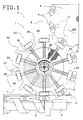
- figure 1 is a schematic plan view, wherein some details have been removed for the sake of clarity, of a filling machine which includes an apparatus according to the present invention;
- figure 2 is a schematic elevation view of the apparatus of figure 1; and
- figure 3 is a schematic elevation view of a further embodiment of the apparatus of figure 2.
- With reference to figure 1, the
reference numeral 1 generally indicates an apparatus for the transfer of products, constituted for example bycontainers 2. The apparatus may constitute part of a machine for fillingcontainers 2 with liquid substances which is only partially illustrated and is generally indicated by 3. - The
transfer apparatus 1 comprises feeder means constituted by a horizontal belt conveyor 4 a first portion whereof is arranged to the side of, and is partially surmounted by, a worm-screw orauger conveyor 5 which is driven by amotor 6 and is capable of transferring thecontainers 2 in succession toward arotary conveyor 7, adapted to transfer thecontainers 2 along a curved path. Theconveyor 7 passescontainers 2 in succession to arotary filling conveyor 8 which, in a manner which is known and thus not described, fills thecontainers 2 with a liquid and conveys them to a closure station, which is not illustrated for clarification purposes. - The
filling conveyor 8 essentially comprises adrum 9 with a vertical axis which rotates in a clockwise direction as indicated by thearrow 100 in figure 1. Thefilling conveyor 8 peripherally supports a plurality of mutually equidistant housings orseats 10, each of which is adapted to accommodate acontainer 2 and to retain it by means of suction means constituted for example by asucker 11. - With particular reference to figure 2, the
conveyor 7 comprises arotary conveyor element 12 with a vertical axis which is adapted to transfer thecontainers 2 along a curved path by rotating anti-clockwise. Saidrotary conveyor element 12 is keyed on the upper portion of a verticalhollow shaft 13 which is rotated by motor means, not illustrated, by means of agearwheel 14 which is keyed to its lower end. Theshaft 13 is rotatably supported, below theconveyor element 12, by means of asleeve 15 which is rigidly associated with ahorizontal wall 16, advantageously constituting a portion of the base of thefilling machine 3, and being arranged coaxial to a lower portion of saidshaft 13. Due to reasons which will become apparent hereinafter, said lower portion is connected to a source of compressedair 17. - A cup-
shaped body 18, with its concavity directed upward, is coaxially connected to an upper portion of thesleeve 15 and coaxially supports an annular supportingelement 19 which is arranged horizontally. - The
conveyor element 12 comprises a cup-like body 20 which has its concavity directed upward, is keyed coaxially on theshaft 13 directly above thesleeve 15 and supports, in an upward position, a plurality of radially slidable retention elements or holder means 23 (ten in the illustrated case) by means ofradial rails 21 defined in anupper surface 22 ofsaid body 20. - Each
retention element 23 comprises aslider 24 adapted to slide within arespective rail 21, which supports arest element 25 at an end thereof directed toward the outside of theconveyor element 12. A retention means, constituted by asucker 26, protrudes toward the outside of theconveyor element 12 through eachrest element 25. - Each
sucker 26 communicates through aduct 27, to an intermediate portion of avertical duct 28 which is defined in ablock 29, supported by a lower wall of the cup-like body 20. Theduct 28 has an upper end which communicates with the atmosphere and a lower end connected, by means of aduct 30, to avalve element 31 which is also supported by a lower portion of the cup-like body 20. - Each of the
ducts 28 is in the shape of a Venturi tube and has an intermediate neck-like portion to which theduct 27 leads. - Each
valve element 31 has its own inlet connected to the inside of thehollow shaft 13 which, according to what has been described, is connected to thecompressed air source 17, and has its outlet connected to the lower end of therelated duct 28. Eachvalve element 31 can be actuated, so as to activate or cutoff the connection between therelated sucker 26 and the inside of thehollow shaft 13, by a fixed cam means 32 which is supported by the upper surface of the cup-like body 18. - An adjustment means 33 abuts against the upper surface of the
sliders 24 and comprises a disk-like element 34 which is rotatably and coaxially supported by theshaft 13 by means of asleeve 34′, coaxial to saidshaft 13 and constituting an upper extension of a central portion of the cup-like body 20. Said disk-like element 34 is traversed, in a downward position, by an actuation means, advantageously constituted by aplanar thread 35, which can have one or more starts. Thethread 35 substantially has the shape of an Archimedean spiral and grips engagement means, expediently constituted byflanking grooves 36, provided on the upper surface of thesliders 24. -
Follower elements 37, equal in number to thesuckers 26, extend toward the outside of theconveyor element 12 from the disk-like element 34 and are, in a rearward position (with reference to the direction of rotation of the conveyor 7), in contact with thecontainers 2 which, as will become apparent hereinafter, are retained by thesuckers 26 during the rotation of theconveyor element 12. - Above the disk-
like element 34, theshaft 13 coaxially and rotatably supports atubular element 38 which rests, with its lower end, on the upper surface of the disk-like element 34 and is surmounted by aplate 39 which is coaxial to theshaft 13 and is in turn surmounted by alocking element 40. Saidlocking element 40 is constituted by avertical stem 41 which is threaded and screwed on the upper end of theshaft 13 in a downward position and has anactuation handgrip 42 in an upward position. The upper end of thetubular element 38 has a lateralannular protrusion 43 which acts against, in an upward position, ahelical spring 44 which is coiled around saidtubular element 38 and has a lower end arranged in contact with the upper surface of the disk-like element 34. - In use, the
containers 2 are fed in succession, by means of thebelt conveyor 4 and theauger conveyor 5, into contact withrespective rest elements 25 and withrespective follower elements 37 of theconveyor element 12. Thecontainers 2 are retained in contact with saidfollower elements 37 by therelated suckers 26. Thesuckers 26 in fact start to aspirate at the instant in which they receive acontainer 2, since thevalve element 31, under the action of the cam means 32, connects said end of theduct 27 to the inner cavity of theshaft 13, which communicates with thecompressed air source 17. - The
containers 2, sliding on the upper surface of theannular element 19, are then conveyed in succession intorespective seats 10 of thefilling conveyor 8 to which saidcontainers 2 are passed as a consequence of a further actuation of thevalve element 31 by the cam means 32. - If it is necessary to adapt the
filling machine 3 to the handling of containers with different dimensions with respect to those of thecontainers 2 for which themachine 3 was preset, it is first of all necessary, with themachine 3 stopped, to unscrew thestem 41 of thelocking element 40 by acting on theactuation handgrip 42. The disk-like element 34 must then be rotated manually about its own axis, in one direction or the other, so as to cause, by virtue of the engagement of theplanar thread 35 with thegrooves 36 of thesliders 24, the approach or respectively the spacing-apart of saidsliders 24 from the axis of theshaft 13. Said approach or spacing-apart has the effect of modifying the position of thesuckers 26 so as to create, between the pairs ofcontiguous follower elements 37, a space with such dimensions as to be able to accommodate, in a correct position, a container with different dimensions. - After the
suckers 26 have assumed their new position, the disk-like element 34 must then be positioned, with a small rotation about its own axis which does not appreciably affect the position assumed by thesuckers 26, so that thefollower elements 37 become arranged in such a position as to correctly contact, in a rearward position with reference to the direction of rotation of theconveyor 7, the containers with different dimensions which saidconveyor 7 is to convey. - The
stem 41 of thelocking element 40 is then screwed back onto theshaft 13 by acting on theactuation handgrip 42 so as to cause thetubular element 38 to firmly engage the upper surface of the disk-like element 34 in abutment engagement relationship therewith, and to rigidly reassociate said disk-like element 34 with theshaft 13. - After these simple adjustments, and with no replacement of any mechanical parts, the machine is adjusted for the handling of differently sized containers and is ready to be restarted.
- Obviously, numerous variations of the
apparatus 1 are possible without altering the concept of the invention. - According to another embodiment of the present invention which is not illustrated, the
follower elements 37 may be omitted, since thesuckers 26 may be used alone to keep thecontainers 2 arranged in contact with therest elements 25. - The disk-
like element 34 may furthermore be replaced with any equivalent kinematic system capable of producing the described radial displacement of thesliders 24. - It should be furthermore noted that, as an alternative embodiment to what has been described, the
suckers 26 may lead directly, by means of therelated valve elements 31, to asuction pump 17′ instead of to thecompressed air source 17. - According to a further embodiment of the present invention, illustrated in figure 3, the disk-
like element 34 is connected, in an upward position, to acircular plate 45 which is coaxial to theshaft 13 and is keyed to the upper end of ashaft 46 which is contained coaxially within saidshaft 13. - The lower end of the
shaft 46 protrudes downward from theshaft 13 and is connected to the output shaft of amotor 47 which is constituted, for example, by a step motor powered by means of slidingbrushes 48 arranged resting on acommutator 49 of saidmotor 47. - Below the
gearwheel 14, the inner cavity of theshaft 13 communicates, by means ofholes 50 defined in the surface of saidshaft 13, with aduct 51 which leads to a source of suction which is not illustrated. - In use, if it is necessary to adapt the
filling machine 3 to the handling of containers with dimensions differing from those of thecontainers 2 for which themachine 3 has been preset, it is sufficient to activate themotor 47 so as to cause such a rotation of the disk-like element 34 so as to produce, by virtue of the engagement of theplanar thread 35 with thegrooves 36 of thesliders 24, the approach or respectively the spacing-apart of saidsliders 24 from the axis of theshaft 13. - When the
suckers 26 have assumed a new position which is substantially adapted to allow the handling of the containers with new dimensions, the disk-like element 34 is positioned by themotor 47 so that thefollower elements 37 arrange themselves in such a position as to correctly adhere in a rearward position to the containers with new dimensions which saidconveyor 7 is to convey. - From what has been described it is evident that the described
apparatus 1 allows to vary the size of the treated products by means of simple adjustments, without replacing mechanical parts and with operations which require extremely short times. - It is furthermore evident that the absence of fixed elements against which the
containers 2 may drag ensures a particularly delicate handling of said containers by theconveyor 7. - Where technical features mentioned in any claim are followed by reference signs, those reference signs have been included for the sole purpose of increasing the intelligibility of the claims and accordingly such reference signs do not have any limiting effect on the scope of each element identified by way of example by such reference signs.
Claims (7)
- Apparatus for conveying containers comprising conveyor means constituted by a rotary conveyor (7) having a plurality of mutually angularly equidistant holder means (23), each adapted to accommodate a single product (21), wherein each of said holder means (23) is mounted so as to be displaceable in a substantially radial direction on said rotary conveyor (7), adjustment means (34) being provided for modifying the position of said holder means (23) in said substantially radial direction with respect to said rotary conveyor (7), characterized in that each holder means (23) is slidably mounted in said rotary conveyor and comprises a sucker means (26) which is supported by a corresponding slider element (24) which is radially slidable with respect to said rotary conveyor (7), said slider element (24) having engagement means (36) for said adjustment means (34), said adjustment means comprising actuation means (35) enterengaging with said engagement means (35) and being adapted to cause the radial displacement of said slider element (24) with respect to said rotary conveyor (7), and wherein said adjustment means comprises a disk-like element (34) which is coaxialy mounted with respect to said rotary conveyor (7) and comprises a planar spiral thread (35) which is a part of said actuation means and grips said engagement means (36), said engagement means comprising grooves (36) which are provided on a surface of each of said slider elements (24) and grip said planar spiral thread (35).
- Apparatus according to claim 1, characterized in that each of said holder means (23) comprises follower elements (37) which are rotatable together with said rotary conveyor (7) and are arranged, with respect to the corresponding sucker means (26), upstream with reference to the direction of rotation of said rotary conveyor (7), said follower elements (37) being rigidly associated with said disk-like element (34).
- Apparatus according to claim 1, characterized in that it further comprises motor means (47) adapted to act on said adjustment means (34) to vary the position of said holder means (23).
- Apparatus according to claim 3, characterized in that said motor means comprises a step motor (47).
- Apparatus according to any one of claims 1 to 3, characterized in that said sucker means (26) lead to a neck of a duct (28) which is internally shaped as a Venturi tube, a source of compressed air (17) being provided, valve means (31) being furthermore provided to connect said compressed air source (17) to an end of said duct (28).
- Apparatus according to any one of claims 1 to 5, characterized in that said sucker means (26) lead to a suction pump (17'), valve means (31) being provided to connect said sucker means (26) to said suction pump (17').
- Apparatus according to claim 1, characterized in that said actuation means (35) are adapted to cause simultaneously equal radial displacement of all of said slider elements (24) with respect to said rotary conveyor (7).
Applications Claiming Priority (2)
| Application Number | Priority Date | Filing Date | Title |
|---|---|---|---|
| IT8903504A IT1233303B (en) | 1989-06-07 | 1989-06-07 | EQUIPMENT FOR CONVEYING PRODUCTS |
| IT350489 | 1989-06-07 |
Publications (3)
| Publication Number | Publication Date |
|---|---|
| EP0401698A2 EP0401698A2 (en) | 1990-12-12 |
| EP0401698A3 EP0401698A3 (en) | 1991-06-05 |
| EP0401698B1 true EP0401698B1 (en) | 1994-08-24 |
Family
ID=11108619
Family Applications (1)
| Application Number | Title | Priority Date | Filing Date |
|---|---|---|---|
| EP90110459A Expired - Lifetime EP0401698B1 (en) | 1989-06-07 | 1990-06-01 | Apparatus for conveying products |
Country Status (6)
| Country | Link |
|---|---|
| US (1) | US5058731A (en) |
| EP (1) | EP0401698B1 (en) |
| JP (1) | JPH0326607A (en) |
| DE (1) | DE69011749T2 (en) |
| ES (1) | ES2057273T3 (en) |
| IT (1) | IT1233303B (en) |
Cited By (11)
| Publication number | Priority date | Publication date | Assignee | Title |
|---|---|---|---|---|
| WO2011139577A1 (en) | 2010-05-07 | 2011-11-10 | The Procter & Gamble Company | Universally adjustable star wheel |
| WO2011139565A1 (en) | 2010-05-07 | 2011-11-10 | The Procter & Gamble Company | Adjustable star wheel |
| AU2008303374B2 (en) * | 2007-09-24 | 2013-06-13 | Zepf Technologies Uk Limited | Adjustable star wheel |
| WO2013109414A1 (en) | 2012-01-17 | 2013-07-25 | The Procter & Gamble Company | Adjustable guide rail assemblies |
| WO2015071111A1 (en) | 2013-11-12 | 2015-05-21 | Khs Gmbh | Transport star having an adjustable star pockets – nonius star |
| DE102013113292A1 (en) | 2013-12-02 | 2015-06-18 | Khs Gmbh | Transport star with adjustable star pockets |
| US9181043B1 (en) | 2014-06-03 | 2015-11-10 | The Procter & Gamble Company | Elevation change system for a rotary device |
| US9302856B2 (en) | 2014-06-03 | 2016-04-05 | The Procter & Gamble Company | Method for adjusting a rotary device |
| US9371195B2 (en) | 2014-06-03 | 2016-06-21 | The Procter & Gamble Company | Adjustment system for a rotary device |
| US10315860B2 (en) | 2016-05-25 | 2019-06-11 | The Procter And Gamble Company | Article handling device |
| US11261037B2 (en) | 2017-11-02 | 2022-03-01 | Bausch + Ströbel Maschinenfabrik Ilshofen GmbH + Co. KG | Adjustable vacuum wheel |
Families Citing this family (22)
| Publication number | Priority date | Publication date | Assignee | Title |
|---|---|---|---|---|
| DE59101826D1 (en) * | 1990-04-20 | 1994-07-14 | Balzers Hochvakuum | Device for holding and cooling adjacent workpieces and carriers for several devices. |
| CH687248A5 (en) * | 1991-10-30 | 1996-10-31 | Mitsubishi Heavy Ind Ltd | Dosenzufuehreinrichtung for a seaming machine. |
| GB9314647D0 (en) * | 1993-07-15 | 1993-08-25 | Pakcentre Limited | Methods for conveying objects through apparatus,packing apparatus and methods for packing materials in cartons |
| JP3563108B2 (en) * | 1994-05-27 | 2004-09-08 | 株式会社アドバンテスト | Device transport mechanism for IC test handler |
| US5681597A (en) * | 1996-02-06 | 1997-10-28 | Liquid Container L.P. | Vacuum conveyor picker for blow bottle container |
| US6652215B1 (en) * | 1998-11-05 | 2003-11-25 | Sepha Pharmaceutical | Rotary deblistering apparatus |
| IL163685A0 (en) | 2002-02-25 | 2005-12-18 | Diffusion Pharmaceuticals Llc | Bipolar trans carotenoid salts and their uses |
| EA017982B1 (en) | 2005-02-24 | 2013-04-30 | ДИФФЬЮЖН ФАРМАСЬЮТИКАЛЗ ЭлЭлСи | Trans carotenoids-based pharmaceutical composition and methods for treating tumour |
| US20080092569A1 (en) * | 2006-10-20 | 2008-04-24 | Doberstein Andrew J | Cooling unit with multi-parameter defrost control |
| EP2146948A4 (en) | 2007-04-13 | 2010-08-04 | Diffusion Pharmaceuticals Llc | Use of bipolar trans carotenoids as a pretreatment and in the treatment of peripheral vascular disease |
| AU2008319225B2 (en) | 2007-10-31 | 2016-09-29 | Diffusion Pharmaceuticals Llc | A new class of therapeutics that enhance small molecule diffusion |
| ITPR20080039A1 (en) | 2008-06-10 | 2009-12-11 | Lanfranchi Srl | MACHINE TO ORDER AND ALIGN PLASTIC CUMULATED CONTAINERS IN A DISORDERED MANNER. |
| EP2575487B1 (en) | 2010-06-02 | 2017-10-18 | Diffusion Pharmaceuticals Llc | Oral formulations of bipolar trans carotenoids |
| DE102011111321A1 (en) | 2011-08-26 | 2013-02-28 | Khs Gmbh | filling |
| FR3026097B1 (en) * | 2014-09-19 | 2017-09-29 | Visio Nerf | DEVICE FOR TRANSFERRING WORKPIECES |
| EP3023366B1 (en) * | 2014-11-24 | 2017-03-15 | Jaime Marti Sala | Rotary conveyor with change of pitch for transferring containers |
| CN106552878B (en) * | 2016-11-08 | 2019-01-25 | 广州庆达汽车零部件有限公司 | A kind of automobile front subframe sheet metal component self-feeding processing unit (plant) |
| CN106583574B (en) * | 2016-11-26 | 2019-01-11 | 宁波宏科汽车部件有限公司 | A kind of vehicle beam welding sub-unit punching press feeding mechanism |
| CN108820915B (en) * | 2018-06-12 | 2020-07-14 | 无锡市盛宝嘉科技有限公司 | Automatic change rotatory feed bin |
| CN114435952B (en) * | 2022-03-02 | 2022-09-06 | 广东建嵘智能设备有限公司 | State adjusting device, arranging system and arranging method for packaging containers |
| CN114589372B (en) * | 2022-04-22 | 2022-11-04 | 明光市锐创电气有限公司 | Small-size transformer unloading mechanism and soldering tin system thereof |
| CN115351570A (en) * | 2022-09-01 | 2022-11-18 | 宁波海信紧固件有限公司 | Locknut inner circle fillet processing equipment |
Citations (1)
| Publication number | Priority date | Publication date | Assignee | Title |
|---|---|---|---|---|
| JPS518077A (en) * | 1974-07-09 | 1976-01-22 | Tokico Ltd | UNBINSOCHI |
Family Cites Families (5)
| Publication number | Priority date | Publication date | Assignee | Title |
|---|---|---|---|---|
| GB1419247A (en) * | 1972-02-17 | 1975-12-24 | Jackson J M | Take off and stacker for container printing machine |
| US3961697A (en) * | 1974-03-20 | 1976-06-08 | R. A. Jones & Company Inc. | Apparatus for shingling and packing of articles |
| DE3143511A1 (en) * | 1981-11-03 | 1983-05-11 | Pirzer, Carl, 8402 Neutraubling | INPUT AND OUTLET STAR |
| DE3760733D1 (en) * | 1986-05-23 | 1989-11-16 | Uhlmann Maschf Josef | Device for picking-up, transferring and depositing flat packaging articles for packaging machines |
| JP2615893B2 (en) * | 1988-08-17 | 1997-06-04 | 澁谷工業株式会社 | Rotary article processing equipment |
-
1989
- 1989-06-07 IT IT8903504A patent/IT1233303B/en active
-
1990
- 1990-05-23 US US07/527,400 patent/US5058731A/en not_active Expired - Fee Related
- 1990-06-01 ES ES90110459T patent/ES2057273T3/en not_active Expired - Lifetime
- 1990-06-01 DE DE69011749T patent/DE69011749T2/en not_active Expired - Fee Related
- 1990-06-01 EP EP90110459A patent/EP0401698B1/en not_active Expired - Lifetime
- 1990-06-07 JP JP2147541A patent/JPH0326607A/en active Pending
Patent Citations (1)
| Publication number | Priority date | Publication date | Assignee | Title |
|---|---|---|---|---|
| JPS518077A (en) * | 1974-07-09 | 1976-01-22 | Tokico Ltd | UNBINSOCHI |
Cited By (15)
| Publication number | Priority date | Publication date | Assignee | Title |
|---|---|---|---|---|
| AU2008303374B2 (en) * | 2007-09-24 | 2013-06-13 | Zepf Technologies Uk Limited | Adjustable star wheel |
| US8820514B2 (en) | 2010-05-07 | 2014-09-02 | The Procter & Gamble Company | Universally adjustable star wheel |
| US9340364B2 (en) | 2010-05-07 | 2016-05-17 | The Procter & Gamble Company | Automated adjustment system for star wheel |
| WO2011139565A1 (en) | 2010-05-07 | 2011-11-10 | The Procter & Gamble Company | Adjustable star wheel |
| US8418836B2 (en) | 2010-05-07 | 2013-04-16 | The Procter & Gamble Company | Universally adjustable star wheel |
| US8813950B2 (en) | 2010-05-07 | 2014-08-26 | The Procter & Gamble Company | Automated adjustment system for star wheel |
| WO2011139577A1 (en) | 2010-05-07 | 2011-11-10 | The Procter & Gamble Company | Universally adjustable star wheel |
| WO2013109414A1 (en) | 2012-01-17 | 2013-07-25 | The Procter & Gamble Company | Adjustable guide rail assemblies |
| WO2015071111A1 (en) | 2013-11-12 | 2015-05-21 | Khs Gmbh | Transport star having an adjustable star pockets – nonius star |
| DE102013113292A1 (en) | 2013-12-02 | 2015-06-18 | Khs Gmbh | Transport star with adjustable star pockets |
| US9181043B1 (en) | 2014-06-03 | 2015-11-10 | The Procter & Gamble Company | Elevation change system for a rotary device |
| US9302856B2 (en) | 2014-06-03 | 2016-04-05 | The Procter & Gamble Company | Method for adjusting a rotary device |
| US9371195B2 (en) | 2014-06-03 | 2016-06-21 | The Procter & Gamble Company | Adjustment system for a rotary device |
| US10315860B2 (en) | 2016-05-25 | 2019-06-11 | The Procter And Gamble Company | Article handling device |
| US11261037B2 (en) | 2017-11-02 | 2022-03-01 | Bausch + Ströbel Maschinenfabrik Ilshofen GmbH + Co. KG | Adjustable vacuum wheel |
Also Published As
| Publication number | Publication date |
|---|---|
| IT1233303B (en) | 1992-03-26 |
| IT8903504A0 (en) | 1989-06-07 |
| JPH0326607A (en) | 1991-02-05 |
| EP0401698A2 (en) | 1990-12-12 |
| ES2057273T3 (en) | 1994-10-16 |
| US5058731A (en) | 1991-10-22 |
| DE69011749T2 (en) | 1995-02-16 |
| DE69011749D1 (en) | 1994-09-29 |
| EP0401698A3 (en) | 1991-06-05 |
Similar Documents
| Publication | Publication Date | Title |
|---|---|---|
| EP0401698B1 (en) | Apparatus for conveying products | |
| EP0113703B1 (en) | Combination machine for assembling container components | |
| EP1597150B1 (en) | Apparatus for forming containers | |
| US5450706A (en) | Single twist bunch wrapping machine | |
| US2359932A (en) | Closure applying machine | |
| US3753509A (en) | Bottle uncaser-single liner | |
| CN111873636A (en) | Vertical ampoule color-jet printing production line | |
| CN212422556U (en) | Vertical ampoule color-jet printing production line | |
| EP0399354A1 (en) | Apparatus for correctly positioning dispensers to be applied to containers | |
| JPS6362410B2 (en) | ||
| US2950671A (en) | Article handling apparatus for offset printers | |
| US4594768A (en) | Trimming ceramic flatware | |
| US2294274A (en) | Apparatus for handling biscuits and like articles | |
| CN1065200A (en) | Equipment for filling capsules | |
| US2319900A (en) | Apparatus for packing foodstuffs in cans | |
| JPH0466414A (en) | Receptacle processing device | |
| EP1808376B1 (en) | Method and assembly for separating opening devices supplied jointly in the form of a sheet and applied individually to respective packages of pourable food products | |
| WO1987002623A1 (en) | Automatic handling and screen printing apparatus | |
| US3176823A (en) | Transfer mechanism for tubular articles | |
| EP0373396A1 (en) | Apparatus for filling containers | |
| EP0483712A1 (en) | Apparatus for applying closures to containers | |
| JP4005309B2 (en) | Feeder mechanism and hopper for two different types of cartons | |
| US4907504A (en) | Apparatus for repositioning containers | |
| JPH04228024A (en) | Apparatus for timely supplying fish into fish-processing machine | |
| US3089614A (en) | Dispenser for conical members |
Legal Events
| Date | Code | Title | Description |
|---|---|---|---|
| PUAI | Public reference made under article 153(3) epc to a published international application that has entered the european phase |
Free format text: ORIGINAL CODE: 0009012 |
|
| AK | Designated contracting states |
Kind code of ref document: A2 Designated state(s): DE ES FR GB |
|
| PUAL | Search report despatched |
Free format text: ORIGINAL CODE: 0009013 |
|
| AK | Designated contracting states |
Kind code of ref document: A3 Designated state(s): DE ES FR GB |
|
| 17P | Request for examination filed |
Effective date: 19911004 |
|
| 17Q | First examination report despatched |
Effective date: 19930312 |
|
| GRAA | (expected) grant |
Free format text: ORIGINAL CODE: 0009210 |
|
| AK | Designated contracting states |
Kind code of ref document: B1 Designated state(s): DE ES FR GB |
|
| REF | Corresponds to: |
Ref document number: 69011749 Country of ref document: DE Date of ref document: 19940929 |
|
| REG | Reference to a national code |
Ref country code: ES Ref legal event code: FG2A Ref document number: 2057273 Country of ref document: ES Kind code of ref document: T3 |
|
| ET | Fr: translation filed | ||
| PLBE | No opposition filed within time limit |
Free format text: ORIGINAL CODE: 0009261 |
|
| STAA | Information on the status of an ep patent application or granted ep patent |
Free format text: STATUS: NO OPPOSITION FILED WITHIN TIME LIMIT |
|
| 26N | No opposition filed | ||
| PGFP | Annual fee paid to national office [announced via postgrant information from national office to epo] |
Ref country code: FR Payment date: 19980422 Year of fee payment: 9 |
|
| PGFP | Annual fee paid to national office [announced via postgrant information from national office to epo] |
Ref country code: DE Payment date: 19980522 Year of fee payment: 9 |
|
| PGFP | Annual fee paid to national office [announced via postgrant information from national office to epo] |
Ref country code: GB Payment date: 19980529 Year of fee payment: 9 |
|
| PGFP | Annual fee paid to national office [announced via postgrant information from national office to epo] |
Ref country code: ES Payment date: 19980615 Year of fee payment: 9 |
|
| PG25 | Lapsed in a contracting state [announced via postgrant information from national office to epo] |
Ref country code: GB Free format text: LAPSE BECAUSE OF NON-PAYMENT OF DUE FEES Effective date: 19990601 |
|
| PG25 | Lapsed in a contracting state [announced via postgrant information from national office to epo] |
Ref country code: ES Free format text: LAPSE BECAUSE OF NON-PAYMENT OF DUE FEES Effective date: 19990602 |
|
| PG25 | Lapsed in a contracting state [announced via postgrant information from national office to epo] |
Ref country code: FR Free format text: THE PATENT HAS BEEN ANNULLED BY A DECISION OF A NATIONAL AUTHORITY Effective date: 19990630 |
|
| GBPC | Gb: european patent ceased through non-payment of renewal fee |
Effective date: 19990601 |
|
| PG25 | Lapsed in a contracting state [announced via postgrant information from national office to epo] |
Ref country code: DE Free format text: LAPSE BECAUSE OF NON-PAYMENT OF DUE FEES Effective date: 20000503 |
|
| REG | Reference to a national code |
Ref country code: FR Ref legal event code: ST |
|
| REG | Reference to a national code |
Ref country code: ES Ref legal event code: FD2A Effective date: 20010503 |