EP0401638B1 - Package structure and transmission of the information generated by a video signal encoder - Google Patents
Package structure and transmission of the information generated by a video signal encoder Download PDFInfo
- Publication number
- EP0401638B1 EP0401638B1 EP90110095A EP90110095A EP0401638B1 EP 0401638 B1 EP0401638 B1 EP 0401638B1 EP 90110095 A EP90110095 A EP 90110095A EP 90110095 A EP90110095 A EP 90110095A EP 0401638 B1 EP0401638 B1 EP 0401638B1
- Authority
- EP
- European Patent Office
- Prior art keywords
- data
- transmission
- packages
- sources
- path
- Prior art date
- Legal status (The legal status is an assumption and is not a legal conclusion. Google has not performed a legal analysis and makes no representation as to the accuracy of the status listed.)
- Expired - Lifetime
Links
Images


Classifications
-
- H—ELECTRICITY
- H04—ELECTRIC COMMUNICATION TECHNIQUE
- H04N—PICTORIAL COMMUNICATION, e.g. TELEVISION
- H04N19/00—Methods or arrangements for coding, decoding, compressing or decompressing digital video signals
-
- H—ELECTRICITY
- H04—ELECTRIC COMMUNICATION TECHNIQUE
- H04N—PICTORIAL COMMUNICATION, e.g. TELEVISION
- H04N19/00—Methods or arrangements for coding, decoding, compressing or decompressing digital video signals
- H04N19/10—Methods or arrangements for coding, decoding, compressing or decompressing digital video signals using adaptive coding
- H04N19/134—Methods or arrangements for coding, decoding, compressing or decompressing digital video signals using adaptive coding characterised by the element, parameter or criterion affecting or controlling the adaptive coding
- H04N19/146—Data rate or code amount at the encoder output
- H04N19/152—Data rate or code amount at the encoder output by measuring the fullness of the transmission buffer
-
- H—ELECTRICITY
- H04—ELECTRIC COMMUNICATION TECHNIQUE
- H04N—PICTORIAL COMMUNICATION, e.g. TELEVISION
- H04N19/00—Methods or arrangements for coding, decoding, compressing or decompressing digital video signals
- H04N19/50—Methods or arrangements for coding, decoding, compressing or decompressing digital video signals using predictive coding
- H04N19/593—Methods or arrangements for coding, decoding, compressing or decompressing digital video signals using predictive coding involving spatial prediction techniques
-
- H—ELECTRICITY
- H04—ELECTRIC COMMUNICATION TECHNIQUE
- H04N—PICTORIAL COMMUNICATION, e.g. TELEVISION
- H04N19/00—Methods or arrangements for coding, decoding, compressing or decompressing digital video signals
- H04N19/60—Methods or arrangements for coding, decoding, compressing or decompressing digital video signals using transform coding
- H04N19/61—Methods or arrangements for coding, decoding, compressing or decompressing digital video signals using transform coding in combination with predictive coding
-
- H—ELECTRICITY
- H04—ELECTRIC COMMUNICATION TECHNIQUE
- H04N—PICTORIAL COMMUNICATION, e.g. TELEVISION
- H04N21/00—Selective content distribution, e.g. interactive television or video on demand [VOD]
- H04N21/20—Servers specifically adapted for the distribution of content, e.g. VOD servers; Operations thereof
- H04N21/23—Processing of content or additional data; Elementary server operations; Server middleware
- H04N21/236—Assembling of a multiplex stream, e.g. transport stream, by combining a video stream with other content or additional data, e.g. inserting a URL [Uniform Resource Locator] into a video stream, multiplexing software data into a video stream; Remultiplexing of multiplex streams; Insertion of stuffing bits into the multiplex stream, e.g. to obtain a constant bit-rate; Assembling of a packetised elementary stream
- H04N21/2365—Multiplexing of several video streams
- H04N21/23655—Statistical multiplexing, e.g. by controlling the encoder to alter its bitrate to optimize the bandwidth utilization
-
- H—ELECTRICITY
- H04—ELECTRIC COMMUNICATION TECHNIQUE
- H04N—PICTORIAL COMMUNICATION, e.g. TELEVISION
- H04N21/00—Selective content distribution, e.g. interactive television or video on demand [VOD]
- H04N21/40—Client devices specifically adapted for the reception of or interaction with content, e.g. set-top-box [STB]; Operations thereof
- H04N21/43—Processing of content or additional data, e.g. demultiplexing additional data from a digital video stream; Elementary client operations, e.g. monitoring of home network or synchronising decoder's clock; Client middleware
- H04N21/434—Disassembling of a multiplex stream, e.g. demultiplexing audio and video streams, extraction of additional data from a video stream; Remultiplexing of multiplex streams; Extraction or processing of SI; Disassembling of packetised elementary stream
- H04N21/4347—Demultiplexing of several video streams
-
- H—ELECTRICITY
- H04—ELECTRIC COMMUNICATION TECHNIQUE
- H04N—PICTORIAL COMMUNICATION, e.g. TELEVISION
- H04N19/00—Methods or arrangements for coding, decoding, compressing or decompressing digital video signals
- H04N19/30—Methods or arrangements for coding, decoding, compressing or decompressing digital video signals using hierarchical techniques, e.g. scalability
-
- H—ELECTRICITY
- H04—ELECTRIC COMMUNICATION TECHNIQUE
- H04N—PICTORIAL COMMUNICATION, e.g. TELEVISION
- H04N19/00—Methods or arrangements for coding, decoding, compressing or decompressing digital video signals
- H04N19/50—Methods or arrangements for coding, decoding, compressing or decompressing digital video signals using predictive coding
-
- H—ELECTRICITY
- H04—ELECTRIC COMMUNICATION TECHNIQUE
- H04N—PICTORIAL COMMUNICATION, e.g. TELEVISION
- H04N19/00—Methods or arrangements for coding, decoding, compressing or decompressing digital video signals
- H04N19/70—Methods or arrangements for coding, decoding, compressing or decompressing digital video signals characterised by syntax aspects related to video coding, e.g. related to compression standards
Definitions
- the invention refers to the structure of an encoder (redundancy and bit rate reducer) for video signal, in which it is present more than one source generating the data, that can be for example the video data, the data related to the audio channels, the data describing the state of the encoder, etc., or if it necessary to have resort to the processing of the video information onto N parallel paths (being N equal or greather than 2).
- N equal or greather than 2
- HDTV high definition television signals
- the generation speed of samples can be higher than 100 MHz (interleaved scanning) or at 200 MHz (progressive scanning).
- the redundancy reduction systems it is normal to use variable length codes that adapt the data flow to the entropy characterizing the source. Further it is used, in combination with the information holding variable length words, also the encoding of equal word sequences. In these cases the data generation speed can be greatly time-variable and this happens in each of N processing paths.
- each path word as a data source having a different and time-variable speeds, and it is necessary that these data are shunted correctly.
- An organization suitable for solving these shunting problems is the package technics.
- Each processing path generates data packages supplied with an heading suitable for identifying them, in particular the heading holding the address of the origin path in the encoder, and the destination path in the decoder.
- the organization of packaged data can be extended advantageosly in addition to the strictly video data, also to all tipical information of a television encoder: the lateral informations suitable for describing the device running state, numerical audio signals and eventual further data.
- All above mentioned data are transmitted on a sole transmission path by means of the multiplexer that provides the interleaving of the data packages according to a prefixed time order based on priority criteria.
- the dimension of the package can be selected according to different criteria, but suitable for allowing the use of modular characteristics with which the devices are manufactured, suitable for different applications.
- the more important criteria are as follows: a sole dimension of the packages for the different information types, for different values of transmission speed on the channel and for different formats of the video input signal. An integral number of packages is hold in each transmission frame. Increasing the package dimensions, it is reduced the added redundancy owing to the package heading.
- This figure shows schematically the encoder structure. This figure is sufficient for explaining also the manner in which the decoder runs, the decoder being described only in the details that are considered necessary.
- the tipical functions developped within the blocks of Figure 1 are well-known; see for example "S. Cucchi, F. Molo, DCT based television codec for DS3 digital transmission", preprint No. 130-12, 130th SMPTE technical conference, October 15-19, 1988, New York.
- the input IV(1) shown in Figure 1 receives the data flow representing the colour audio signal in numerical form.
- the input words correspond to the information of the three components forming the video signal, usually these components are Y (luminance) and the two differences R-Y (red minus luminance) and B-Y (bleu less luminance).
- the interface IF(2) carries out the subdivision of the data flow onto N paths, each of these paths corresponding to a sole of the N zones in which the whole image is divided, by means of horizontal or vertical subdivisions. Further this interface supplies further obvious and well-known functions, not pertaining to the present description of the invention.
- the data speed in each of N paths is now reduced to one nth of the input data speed.
- the data pass to the block DC(4).
- This block carries out the typical operations of the redundancy reduction systems; in particular the data are decorrelated, using e.g. the differential PMC of the Cosine Discrete Transform, and then they are encoded for the transmission.
- the possible data encoding methods used in the transmission it is interesting, within the scope of the present invention and how more general case, to use the methods generating the data organized in fixed length words, but with a time-non-uniform rate at the output U(5) of the encoding block.
- FIG. 2 shows the words generated by an encoder using a variable length code by vertical lines.
- This encoder encodes also the null data sequences and attributes to them the different length words, corresponding to the number of zeroes formimng the same sequences.
- This procedure generates the encoding words with an irregular rate over time, as the word is generated in conjunction with the last zero of the sequence and the sequence length obviously is not constant. Further for making easier the data transfer in the system inside and to the transmission line, it can be necessary to organize the variable length words with fixed length words, how it is illustratated in Figure 2b.
- variable length code has some characteristics suitable for allowing the separation, in the decoder, of the single variable length words, starting from the fixed length words.
- the situation present at the output U(5) of Figure 1 of the block DC(4) is related to the first one of N paths in which it is subdivided the original data flow.
- a similar situation is shown at the outputs of remaininng N-1 blocks of decorrelation and encoding, and for each of them the generation rate of the fixed length words is a function of the complexity of the image zone to which the corresponding path is referred. Therefore each one of the N paths is characterized by a different generation rate of the fixed length words, this rate varying over time according to the structure of the encoded image.
- the fixed length words are stored into the buffer memory B(6) (buffer) from which they are drwan by means of the connection UB(7) for being multiplexed by the multiplexer MUX(8) with the words coming from the other N-1 paths.
- the number of words drawn within the time unit in conjunction to each path is non-constant over time.
- the decoder carries out the operations inverse to the formerly described operations and therefore it is also organized by means of N paths. It is necessary that the words coming from the encoder are redistributed in a correct manner among the N paths of the decoder. This can be obtained only supplying the fixed length words with a suitable address identifying the provenance path.
- each package is formed by a prefixed number of fixed length words, for example 100 words, and it is supplied with a further initial identifying word (heading) that holds the address of the source and destination paths.
- heading initial identifying word
- the block codes for the correction and/or the error survey and the data are organized according to interlaced structures (interleaving).
- the dimensions and the structure of packages can be established according to these schemes of error protection for optimizing its practical fulfilment and its efficiency.
- the multiplexer works onto the packages, or the minimum unit that is transferred by one of the N buffers to the multiplexer MUX(8) is formed by a package.
- each package can correspond to a more o less extended image area, always according to its complexity.
- the buffer controller, the block CB(9) works for assuring that each buffer does not arrive to the complete emptying conditions (underflow) or overload (overflow) and that the packages hold therewithin are drawn from the multiplexer according to the time order with which its generation was started.
- connection SP(10) Each time it is started the generation of a new package in the inside of one of the N buffers, this event is signaled by means of the connection SP(10) to the buffer controller. Then the controller provides to supply, by the connection IP(11), the information of package heading, holding the address of the source and destination path and to store the same informations in its inside.
- the controller can establish the availabile package of older generation time and can order, by means of the connection IP(11), to the buffer of the related path to make the transfer of the above mentioned package to the multiplexer.
- the controller provides further to change, by means of the connection CD(13), the running mode of the decorrelator/encoder with the aim of adapting the generated information flow.
- the lateral information block UL(18) and for example the video sources (connection UD(19)) generate the data with a fixed bit rate and greatly under the bit rate of the transmission line (output Tx(20); the remaining part of the line bit rate is filled with the video data, whose mean bit rate is controlled as indicated above.
- the control of the buffers corresponding to the N paths can be made according to different modalities, according to the applied compromises.
- the buffers can be controlled singularly.
- the controller causes the summation of seizures of the various buffers never to execeed the limit MP and the decorrelators/encoders to work with the same precision.
- This solution does not allow an optimal use of the total buffer capacity, equal to MNP, but allows a notable simplification of the buffer controller.
- control of the single buffers can be carried out as it were a sole buffer, operating onto the single decorrelators/encoders or it is possible to use a sole buffer joined to the outputs of the N decorrelators/encoders.
- FIG. 3 is drawn under the hypotesis that 3 video signal processing paths are present and B(1), B(2), B(3) show the buffers connected in the encoding side onto the three processing paths where the data flows enter respectively the inputs E(1), E(2), E(3); these data flows have for example the structure indicated in Figure 2b and hold the words that supply the package heading suitable allocated over time, so that the package-built data enter the transmission buffers, even when words forming the package enter the buffers with a rate variable over time.
- the packages already stored in the buffers B(1), B82), B(3) are transmitted, according to suitable sequences and by means of the connections C(1), C(2), C(3) to the transmission path, indicated schematically in Figure 3 by means of the connection TR(1) that includes the real transmission path and the signal multiplexer and demultiplexer.
- the packages are sent, without its heading, onto the reception buffers B′(1), B′(2), B′(3).
- the reception buffer outputs read the data (for example the words holding 32 bit, as indicated in Figure 2b) with an irregular rate that allows to reconstruct the parts of video images in reception.
- this line transmits the data on E(1) and U(1) at a mean speed got in a short period, with a rate R1 variable over time but equal with one another.
- the data speed (bit per second) on the connection E(1) for a certain part of television image when the same part of television image is reconstructed in reception, then in this instant the data speed on the connection U(1) is equal to the speed present in E(1) for the same part of television image.
- Ro is the data speed in line (or at least the part of the line speed provided for the video data) and it is constant.
- the product Ro ⁇ ⁇ o is constant, therefore it is obtained that the total seizure of buffers in transmission and reception are complementary with one another, that further assures a constant value of the transmission delay due to the total buffers of transmission and reception.
- the manner for controlling the seizure value of Oo (and then, as consequence, the value of Oo′) is shown in the above mentioned article by S. Cucchi and F. Molo.
- each value Oi can be assumed in general as a function of the related value Ri and further in the generical time To an information proportional to Ri must be transmitted in line in each path; the conditions (3) are now achieved imposing that the sum-mation O1 + O2 + O3 is minimum under the condition that, in the generical time To, an information is transmitted to ( R1 + R2 + R3 ). To, and further imposing that Oi tends to zero with Ri.
- the buffers foreseen in the reception side do not require particular provisions, as in the moment the single words of a package are inserted onto a reception buffer, they can be used immediately.
- the control criteria of the buffer similar to the above mentioned criteria can be used.
- the buffer is made in a structure holding sequencially ordered packages, and each package is assigned to a single processing path at the instant in which this package starts to be formed, being so formed, in the buffer inside, an ordering of packages according to to the generation start time of the same packages.
- the transmission of packages onto the transmission line they are transmistted simply according to the just assigned ordering; it is necessary to apply the precaution of accelerating the generation of a package before its transmission on the line, or when few packages precede it in the transmission order onto the transmission line.
- the block related to the lateral information IL(4) collects all informations coming from the various blocks forming the encoder by means of the connections SI(15), SD(16), SC(17) coming respectively from the input interface, from N decorrelation/encoding paths and from the buffer controller.
- These data can be transmitted to the multiplexer MUX(8) by means of the connection UL(18) and be organized as packages in the same format and dimensions of the packages holding the video informations: the provenance of the various packages can be established by means of the use of a suitable heading.
- other ancillary and/or audio informations can be organized in packages of the same format and sent to the multiplexer MUX(8) by means of the input UD(19).
- the multiplexer MUX(8) can be foreseen for treating all package types, according to the transmission path onto the channel, it can interact by means of the connection RP(12) with the buffer controller CB(9). In this manner the system can be adapted to the different transmission speeds.
- the transmission frame holds a frame alignment word, some words for the ancillary services (for example a phonic service channel) and the data related to the video signal, to the lateral informations and audio channels, all of them being organized under the form of packages.
- the priority assigned in transmission is different for the different package types, being for example convenient to assign a higher priority to the lateral information and lower priority to the video data.
- the other data such as the audio channels and the lateral data that send in reception the information related to the encoder running mode, require a fixed line bit rate, that is a fraction of the bit rate of the line Ro, and the remaining part of Ro is assigned to the video signal coming from the adapted sources, that is to say, it is adapted for filling totally the remaining part of Ro.
- the priority to be assigned to the inside of the data coming from the sources generating a fixed bit rate shall be established on the basis of transmission delays, that these data can support.
- the multiplexer MUX(8) develops the typical functions of the multiplexer and in particular, using a suitable interface, provides the transmission of the data, serialized and encoded according to the preset line code, to the output TX(20).
- the decoder has an organization dual with respect to the encoder organization.
- the incoming packages are shunted correctly according to the address hold in the heading, but the buffer controller must keep under control the filling condition of the different buffers and causes the filling to be complementary to the filling of encoding side buffers.
Landscapes
- Engineering & Computer Science (AREA)
- Multimedia (AREA)
- Signal Processing (AREA)
- Compression Or Coding Systems Of Tv Signals (AREA)
- Color Television Systems (AREA)
- Transmission Systems Not Characterized By The Medium Used For Transmission (AREA)
- Communication Control (AREA)
- Time-Division Multiplex Systems (AREA)
- Data Exchanges In Wide-Area Networks (AREA)
Description
- The invention refers to the structure of an encoder (redundancy and bit rate reducer) for video signal, in which it is present more than one source generating the data, that can be for example the video data, the data related to the audio channels, the data describing the state of the encoder, etc., or if it necessary to have resort to the processing of the video information onto N parallel paths (being N equal or greather than 2). This last case appears owing to the technological limitations in the fulfilment of data processing devices or for simple reasons of convenience when the number of video samples present in the time unit at the encoder input is characterized by a very variable field and then it is suitable to have a modular structure. This is the case, for example, of the encoding of high definition television signals (HDTV), in which the generation speed of samples can be higher than 100 MHz (interleaved scanning) or at 200 MHz (progressive scanning). When the information processing is made onto N paths, it is necessary to organize the data so that, once the data are transmitted to the decoder, one can identify the path from which they arrive and to decode correctly the data. In the case in which the redundancy reduction systems are used, it is normal to use variable length codes that adapt the data flow to the entropy characterizing the source. Further it is used, in combination with the information holding variable length words, also the encoding of equal word sequences. In these cases the data generation speed can be greatly time-variable and this happens in each of N processing paths.
- In pratice each path word as a data source having a different and time-variable speeds, and it is necessary that these data are shunted correctly. An organization suitable for solving these shunting problems is the package technics. Each processing path generates data packages supplied with an heading suitable for identifying them, in particular the heading holding the address of the origin path in the encoder, and the destination path in the decoder.
- Further the organization of packaged data can be extended advantageosly in addition to the strictly video data, also to all tipical information of a television encoder: the lateral informations suitable for describing the device running state, numerical audio signals and eventual further data.
- All above mentioned data are transmitted on a sole transmission path by means of the multiplexer that provides the interleaving of the data packages according to a prefixed time order based on priority criteria.
- If all transmission data are organized in packages having a fixed dimension (all holding the same bit number) it is possible to assign a structure to the transmission frame, so that it is adapted to the packaged format and dimension and in consequence the transmission multiplexer placed on the channel shall show an optimal structure for this data organization.
- The dimension of the package can be selected according to different criteria, but suitable for allowing the use of modular characteristics with which the devices are manufactured, suitable for different applications. The more important criteria are as follows: a sole dimension of the packages for the different information types, for different values of transmission speed on the channel and for different formats of the video input signal. An integral number of packages is hold in each transmission frame. Increasing the package dimensions, it is reduced the added redundancy owing to the package heading.
- The common use of N paths for processing the informations and the data package structure allows notable advantages that are listed hereunder:
- modular structure of the encoder, that can be adapted to video sources characterized by very different generation speeds of samples. The control and interface members suitable for recognizing automatically the number of processors (processing paths) can be manufactured.
- a sole encoding device can work onto a sole video source at input using the N paths in parallel, or using a different input interface, onto more video signals attributing to each signal a subassembly of the N processors and the whole transmission capacity.
- multiplexing frame structure suitable for allowing the multiplexer adapation to the different channel transmission speeds and that are eventually time-variable.
- the modular structure allows to adapt the device to the technological development; for example, if the processing speed in each path can be doubled, it is sufficient to halve the number of processors joined in parallel, keeping practically invariable the remaining function blocks of the co-decoder and the frame structure.
- The advantages of the present invention are particularly evidenced in the described case, in which the processing of the video signal is made by means of separated processors and further separated paths are used for transmitting the lateral information and for transmitting the audio signals. But the advantages of the invention are also appreciated when two sole paths must be multiplexed, these paths generating information with speeds (bit rate) shifted with one another, for example a path generates the video data with associated data related to the encoder state and a second path generates the data related to an audio signals series.
- The invention is better explained in the following, making reference to a preferred fulfilment form, illustrated in the Figures 1, 2, 3 and 4.
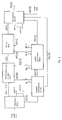
- Figure 1 shows the block scheme of the encoder and evidences the main functions carried out thereby, sufficient for explaining the invention;
- Figure 2 shows a tipical example of the manner in which a video signal processor can generate words having different lengths and with a non-uniform rate (Figure 2a); this rate non-uniformity is mantained and generally increased when the variable length words are packaged for forming fixed length words (Figure 2b).
- Figure 3 shows the case in which three different processing paths (N=3) are used and the three buffers foreseen on the transmission side, the corresponding buffers in the reception side, and further the transmission path intended wholly are shown schematically;
- Figure 4 shows, considering three processing paths, the related time axes with the indication of the time intervals during which the data are stored, these data allowing the formation of the data packages, all having the same length in terms of bit number, these packages using the buffers, in which they are stored temporaneously, and must be transmitted on the transmission line.
- The invention is explained better by the description of a particular fulfilment form thereof, making reference to the Figure 1.
- This figure shows schematically the encoder structure. This figure is sufficient for explaining also the manner in which the decoder runs, the decoder being described only in the details that are considered necessary. Generally the tipical functions developped within the blocks of Figure 1 are well-known; see for example "S. Cucchi, F. Molo, DCT based television codec for DS3 digital transmission", preprint No. 130-12, 130th SMPTE technical conference, October 15-19, 1988, New York.
- The input IV(1) shown in Figure 1 receives the data flow representing the colour audio signal in numerical form. The input words correspond to the information of the three components forming the video signal, usually these components are Y (luminance) and the two differences R-Y (red minus luminance) and B-Y (bleu less luminance).
- The interface IF(2) carries out the subdivision of the data flow onto N paths, each of these paths corresponding to a sole of the N zones in which the whole image is divided, by means of horizontal or vertical subdivisions. Further this interface supplies further obvious and well-known functions, not pertaining to the present description of the invention. The data speed in each of N paths is now reduced to one nth of the input data speed.
- Now it is made reference to any of the N paths: for example, in the case of the first path I(3), the data pass to the block DC(4). This block carries out the typical operations of the redundancy reduction systems; in particular the data are decorrelated, using e.g. the differential PMC of the Cosine Discrete Transform, and then they are encoded for the transmission. Among the possible data encoding methods used in the transmission, it is interesting, within the scope of the present invention and how more general case, to use the methods generating the data organized in fixed length words, but with a time-non-uniform rate at the output U(5) of the encoding block.
- For explaining better this concept, it is made reference to the Figure 2. The Figure 2 shows the words generated by an encoder using a variable length code by vertical lines. This encoder encodes also the null data sequences and attributes to them the different length words, corresponding to the number of zeroes formimng the same sequences. This procedure generates the encoding words with an irregular rate over time, as the word is generated in conjunction with the last zero of the sequence and the sequence length obviously is not constant. Further for making easier the data transfer in the system inside and to the transmission line, it can be necessary to organize the variable length words with fixed length words, how it is illustratated in Figure 2b. This example shows that the fixed length words are formed by 32 bit: the first of these words is formed by 32 bit Pb(1) holding the first four words and a part of the fifth word Pa(2) with variable length shown in Figure 2a. The remaining part of the word Pa(2) added to the following words are held, until the saturation of its capacity equal to 32 bit, into the second fixed length word Pc(3). It is supposed that, how it is made in the practical fulfilments, that the variable length code has some characteristics suitable for allowing the separation, in the decoder, of the single variable length words, starting from the fixed length words. This compacting of the variable length words, just generated with a non-uniform rate, causes the highly irregular generation rate of the fixed length words at the output U(5). As the statistic distribution of the lengths of variable length words depends on the complexity of the encoded image zone, finally this complexity depends also on the generation rate of the fixed length words.
- The situation present at the output U(5) of Figure 1 of the block DC(4) is related to the first one of N paths in which it is subdivided the original data flow. A similar situation is shown at the outputs of remaininng N-1 blocks of decorrelation and encoding, and for each of them the generation rate of the fixed length words is a function of the complexity of the image zone to which the corresponding path is referred. Therefore each one of the N paths is characterized by a different generation rate of the fixed length words, this rate varying over time according to the structure of the encoded image.
- The fixed length words are stored into the buffer memory B(6) (buffer) from which they are drwan by means of the connection UB(7) for being multiplexed by the multiplexer MUX(8) with the words coming from the other N-1 paths. The number of words drawn within the time unit in conjunction to each path is non-constant over time.
- The decoder carries out the operations inverse to the formerly described operations and therefore it is also organized by means of N paths. It is necessary that the words coming from the encoder are redistributed in a correct manner among the N paths of the decoder. This can be obtained only supplying the fixed length words with a suitable address identifying the provenance path.
- For limiting the added redundancy for supplying this address, it can possible to increase the dimension of the single fixed length words, but this can cause the increasing of connections among decorrelator, buffer and multiplexer with unwished effects on the fulfilment circuit complexity. As alternative it can possible to group many fixed length words coming from each single path for forming a package; each package is formed by a prefixed number of fixed length words, for example 100 words, and it is supplied with a further initial identifying word (heading) that holds the address of the source and destination paths. On principle the dimensions of the package can be variable, but for making easier the multiplexing and organization operations of the transmission frame, they are supposed as constant. In particular it is necessary to foresee the introduction of the schemes protecting the information from the errors introduced by the channel: for example it can be used the block codes for the correction and/or the error survey and the data are organized according to interlaced structures (interleaving). The dimensions and the structure of packages can be established according to these schemes of error protection for optimizing its practical fulfilment and its efficiency.
- In the following it is considered as well-known that the packages coming from the different sources are eventually completed with some error protection words (for example in the same multipler) keeping all packages within the same dimension.
- The multiplexer works onto the packages, or the minimum unit that is transferred by one of the N buffers to the multiplexer MUX(8) is formed by a package. As consequence of the time-variable rate, wich each one of the N paths generates the fixed length words, is the non-constant rate, and it is a function of the complexity of the processed image zone, by which each path generates the information packages. Further each package can correspond to a more o less extended image area, always according to its complexity. The buffer controller, the block CB(9) works for assuring that each buffer does not arrive to the complete emptying conditions (underflow) or overload (overflow) and that the packages hold therewithin are drawn from the multiplexer according to the time order with which its generation was started. Each time it is started the generation of a new package in the inside of one of the N buffers, this event is signaled by means of the connection SP(10) to the buffer controller. Then the controller provides to supply, by the connection IP(11), the information of package heading, holding the address of the source and destination path and to store the same informations in its inside. When the multiplexer requires the transmission of a new package by means of the connection RP(12), the controller can establish the availabile package of older generation time and can order, by means of the connection IP(11), to the buffer of the related path to make the transfer of the above mentioned package to the multiplexer.
- In the case in which more packages start to be formed contemporaneously in two or more of the N paths, the arbitrary assignment of the transmission order to these package does not cause underflow problems in the decoder side, owing to the presence of a suitable buffer therewithin, whose existance is in any case necessary.
- According to the situation of buffer seizure, the controller provides further to change, by means of the connection CD(13), the running mode of the decorrelator/encoder with the aim of adapting the generated information flow. Generally speaking, the lateral information block UL(18) and for example the video sources (connection UD(19)) generate the data with a fixed bit rate and greatly under the bit rate of the transmission line (output Tx(20); the remaining part of the line bit rate is filled with the video data, whose mean bit rate is controlled as indicated above.
- The control of the buffers corresponding to the N paths can be made according to different modalities, according to the applied compromises. In particular the buffers can be controlled singularly. In this case, if each buffer has a capacity equal to M.P. package, the controller causes the summation of seizures of the various buffers never to execeed the limit MP and the decorrelators/encoders to work with the same precision. This solution does not allow an optimal use of the total buffer capacity, equal to MNP, but allows a notable simplification of the buffer controller.
- As alternative the control of the single buffers can be carried out as it were a sole buffer, operating onto the single decorrelators/encoders or it is possible to use a sole buffer joined to the outputs of the N decorrelators/encoders. These solutions allow to optimize the dimensions of the buffer memory, but increasing the controller complexity and can be advantageous in the case of an high N value.
- As the normal knowledges of the package transmission of informations coming from more sources are not satisfying for explaining the running of the codec of Figure 1 when the video signal is processed onto more processing paths, each path being supplied with buffer, further details are given in the following with specifical reference to the running manner of the buffers connected in transmission and in reception onto the N processing paths of the video signal and making reference to the Figures 3 and 4.
- The Figure 3 is drawn under the hypotesis that 3 video signal processing paths are present and B(1), B(2), B(3) show the buffers connected in the encoding side onto the three processing paths where the data flows enter respectively the inputs E(1), E(2), E(3); these data flows have for example the structure indicated in Figure 2b and hold the words that supply the package heading suitable allocated over time, so that the package-built data enter the transmission buffers, even when words forming the package enter the buffers with a rate variable over time. The packages already stored in the buffers B(1), B82), B(3) are transmitted, according to suitable sequences and by means of the connections C(1), C(2), C(3) to the transmission path, indicated schematically in Figure 3 by means of the connection TR(1) that includes the real transmission path and the signal multiplexer and demultiplexer. In the reception side, using the connections C(4), C(5), C(6) the packages are sent, without its heading, onto the reception buffers B′(1), B′(2), B′(3). The reception buffer outputs read the data (for example the words holding 32 bit, as indicated in Figure 2b) with an irregular rate that allows to reconstruct the parts of video images in reception.
- If it is considered a particular processing path, e.g. the path starting from the transmission connection E(1) and arriving to the connection path U(1) in reception, both in E(1) and U(1), neglecting the delay caused by the buffers B(1) and B′(1), and further by the transmission line, this line transmits the data on E(1) and U(1) at a mean speed got in a short period, with a rate R1 variable over time but equal with one another. In other terms, if we consider the data speed (bit per second) on the connection E(1) for a certain part of television image, when the same part of television image is reconstructed in reception, then in this instant the data speed on the connection U(1) is equal to the speed present in E(1) for the same part of television image.
- Then in the following the criterium of contemporaneity shall be referred to the above explained criterium. A similar reasoning can be used in the other two processing paths of the signal indicated in Figure 3. If we indicate with Oi (i = 1, 2, 3) the seizure (bit number) of the buffer B(1) and with R(i) the variable data on the path R(i), and further we indicate with Oi′ the seizure of buffers B′(i), the delay ΔO, introduced by the buffers onto the generical path of index i , is given by the expression:

However the values of Ri, Oi and Oi′ are generally different onto three processing paths, the delay value ΔO is equal for the three paths and constant over time. In fact if the three image parts corresponding to the three paths are processed contemporaneously in transmission, they are also processed contemporaneously in reception, therefore the data present in the same instant (excepting little flowings over time, due e.g. to the storage of data in words holding 32 bit and that are stored by the buffers) onto the paths E(i), these same data must be shown in the same time (contemporaneously) on the paths U(i). - The equation (1) supplies really 3 equations for the 3 values of the index i and, summing the three equations, it can be obtained:

where


- The values of Oo, Oo′, Oi, Oi′ and Ri are generally variable over time, but generally the equations (1) and (2) remain valid. In greather detail, being Ro a constant value, the equation:

is valid only in the long period. When the mean complexity of the television image changes, the speeds R1, R2, R3 change, also suddenly, and the above mentioned equation is no more valid in the short period and the difference between the summation of R1, R2 and R3 and the value of Ro is absorbed by the variations of transmission buffer filling, in particular by the variation of Oo and this variation is used on its turn as feedback for the blocks DC(4) of Figure 1 for increasing or reducing the data generation speed. - The equation (1) shows that each single Oi can approach to the maximum allowed value of Oo, in relation to the values assumed by the Ri, therefore each of the three buffers B(i) must have a capacity equal to the maximum allowed capacity, that is to say the maximum value Oo.
- A further binding of the values of Oi, Oi′ and Ri is obtained considering the Figure 4. This figure represents by S(1), S(2), S(3) the three time axes related to the inputs E(1), E(2), E(3) or the outputs U(1), U(2), U(3) and in each axis the time intervals necessary for forming the data packages are limited by vertical lines. For example, in the first path in which the time axis is indicated by S(1), the data package is filled in the time elapsed from T(1) and T(2), the package P(2) is filled in the time elapsed from T(2) and T(3) and similarly for the packages hold in the other paths. Now, if we consider a static condition, in which the data are generated at speed Ri on the three axes S(i), and the data are not sent onto the transmission line TR(1) of Figure 3, the data are stored into the transmission buffers B(i), so that at each instant it is satisfied the equation group:

When it is started the data transmission onto the transmission path TR(1), shown in Figure 3, it is necessary to transmit the data related to the three paths S(i) with speed Ri, and this can be made ordering the whole packages onto the three paths, as regards the order of its transmission onto the transmission line, or according to its order of initial generation time (time T(1) for P(1) in Figure 4) or according to the completion time (T(2) for the package P(1)). The conditions (3) can be achieved also by the following reasoning: each value Oi can be assumed in general as a function of the related value Ri and further in the generical time To an information proportional to Ri must be transmitted in line in each path; the conditions (3) are now achieved imposing that the sum-mation


The equations (3) and (4), in which all variable quantities are variable over time, remain valid in normal running conditions, not considering the data variations in the short period, and are in any case sufficient, together with the equations (1) and (2) to outline a control strategy of buffers (intended on the whole) in transmission and reception. - As reagrds the modalities of package transmission it is remarkably more convenient its transmission according to the corresponding ordering at the start of its generation. In this case it is necessary to control the filling condition of each buffer B(i) on the transmission side, so that in each one of the buffers the filling higher than a package is achieved. This can be obtained in transmission accelerating the generation of the package by means of the insertion of redundancy data that can be recognized and then eliminating these data in the corresponding reception buffer, in this manner accelerating artificially the speed R(i). A similar provision can be used in transmission onto the buffer considered on the whole.
- The buffers foreseen in the reception side do not require particular provisions, as in the moment the single words of a package are inserted onto a reception buffer, they can be used immediately.
- In the case in which we use, instead of a single buffer for each processing path, as indicated in Figure 1, a single buffer in commom to all processing paths, the control criteria of the buffer similar to the above mentioned criteria can be used. In particular the buffer is made in a structure holding sequencially ordered packages, and each package is assigned to a single processing path at the instant in which this package starts to be formed, being so formed, in the buffer inside, an ordering of packages according to to the generation start time of the same packages. As regards the transmission of packages onto the transmission line, they are transmistted simply according to the just assigned ordering; it is necessary to apply the precaution of accelerating the generation of a package before its transmission on the line, or when few packages precede it in the transmission order onto the transmission line. The disdvantage of using a sole buffer as alternative to the single buffers in each processing path is the loss of the modularity in the buffer inside, and further the introduction of informations into the buffer is contested by N processing paths, being so complicated the access control of the information buffer, and further the buffer must operate at an higher speed both in writing and in reading phases.
- The block related to the lateral information IL(4) collects all informations coming from the various blocks forming the encoder by means of the connections SI(15), SD(16), SC(17) coming respectively from the input interface, from N decorrelation/encoding paths and from the buffer controller. These data can be transmitted to the multiplexer MUX(8) by means of the connection UL(18) and be organized as packages in the same format and dimensions of the packages holding the video informations: the provenance of the various packages can be established by means of the use of a suitable heading. Similarly other ancillary and/or audio informations can be organized in packages of the same format and sent to the multiplexer MUX(8) by means of the input UD(19). In the inside of packages coming from the sources of different type, as video, audio sources, etc., different criteria can be used for the data organization and different codes can be used for the error protection, so that they are suited to the particular source characteristics. The multiplexer MUX(8) can be foreseen for treating all package types, according to the transmission path onto the channel, it can interact by means of the connection RP(12) with the buffer controller CB(9). In this manner the system can be adapted to the different transmission speeds.
- The transmission frame holds a frame alignment word, some words for the ancillary services (for example a phonic service channel) and the data related to the video signal, to the lateral informations and audio channels, all of them being organized under the form of packages. The priority assigned in transmission is different for the different package types, being for example convenient to assign a higher priority to the lateral information and lower priority to the video data. It must be noticed that, in any case, excepting the data related to the video signal, the other data, such as the audio channels and the lateral data that send in reception the information related to the encoder running mode, require a fixed line bit rate, that is a fraction of the bit rate of the line Ro, and the remaining part of Ro is assigned to the video signal coming from the adapted sources, that is to say, it is adapted for filling totally the remaining part of Ro. What above mentioned shows the necessity of assigning the higher transmission priority to the signals that occupy (in mean value) a fixed part of the line bit rate.
- The priority to be assigned to the inside of the data coming from the sources generating a fixed bit rate shall be established on the basis of transmission delays, that these data can support. The multiplexer MUX(8) develops the typical functions of the multiplexer and in particular, using a suitable interface, provides the transmission of the data, serialized and encoded according to the preset line code, to the output TX(20).
- As above described, the decoder has an organization dual with respect to the encoder organization. In particular the incoming packages are shunted correctly according to the address hold in the heading, but the buffer controller must keep under control the filling condition of the different buffers and causes the filling to be complementary to the filling of encoding side buffers.
Claims (5)
- A method for transmitting television signals, based on the bit rate reduction and in which the transmission side receives the signals to be transmitted onto the transmission line coming from at least two sources, one of which sources is necessarily the one generating the compressed data related to the video image, the second being a source generating the data describing the state variable over the time of the machine reducing the bit rate of the video signal and/or the source supplying an audio signal under the digital form, these data sources generating the data at a speed variable over time or in any case with speeds that are not correlated in a simple manner, characterized in that:- at the transmission side, the data to be transmitted and generated by two or more sources are structured in packages having an equal length (bit number) and are provided with suitable heading (address) that is used for individualizing at least the source to which the packages belong, these packages being supplied to the transmission line according to a transmission priority;- in the reception path the addresses of the package are recognized and transmitted onto the paths corresponding to the transmission path.
- A method according to claim 1, characterized in that the data packages, formed by data coming from the related sources and under the form of series of binary values or series of words having assigned lengths, are added with words having the aim of making the protection of errors caused by the transmission line.
- A method according to claims 1 and 2, characterized in that the line multiplexer frame holds an integral number of packages coming from the data sources, so that at reception end the recognizing of the transmission frame on the line allows to individualize easily the heading of packages and thus their sorting to the processing paths corresponding to the relevant data source in transmission.
- A method for transmitting television signals based on the bit rate reduction, in which the data of the video source to be processed are shunted onto N processing paths (N ≧ 2), in which each path must now process the data at a speed N-times lower than the speed of the video source and, downstream the processing, each path generates data at a different speed, the data generated by the N sources of processed data must be sent onto the transmission line together with the data coming from other data sources that can be the source of data describing the state of the bit rate machine, both globally and considering the N processing paths, or the source of data related to the audio channels or other signals, characterized in that:- at the transmission end at least the data coming from the N processing paths are grouped, in each single path, under the form of packages having an equal length and supplied with suitable heading used for individualizing at least to which of the N processing paths the package is related, these packages being sent onto the transmission line using a line multiplexer, having a priority assigned to each of the N paths, corresponding to the time order with which the data of the single packages have started to be stored in the package related to each processing path;- on the reception path the source address among the N transmission processing sources is recognized by the reception demultiplexer that provides to send the package onto the reception processing path corresponding to the transmission path.
- A method according to claim 4, characterized in that both for the N processing paths of the video signal and for the sources of the other data, some packages having equal length are formed (number of information bits), supplied each with a heading specifying at least the source that has originated the package, these packages being transmitted onto the transmission line by a suitable line multiplexer, according to a further priority order assigned to the assembly of the processed N video data sources and singularly to the other sources of data to be transmitted onto the transmission line.
Applications Claiming Priority (2)
| Application Number | Priority Date | Filing Date | Title |
|---|---|---|---|
| IT2081089 | 1989-06-07 | ||
| IT8920810A IT1230235B (en) | 1989-06-07 | 1989-06-07 | STRUCTURING AND PACKAGE TRANSMISSION OF THE INFORMATION GENERATED BY CODER FOR VIDEO SIGNALS. |
Publications (2)
| Publication Number | Publication Date |
|---|---|
| EP0401638A1 EP0401638A1 (en) | 1990-12-12 |
| EP0401638B1 true EP0401638B1 (en) | 1994-08-10 |
Family
ID=11172389
Family Applications (1)
| Application Number | Title | Priority Date | Filing Date |
|---|---|---|---|
| EP90110095A Expired - Lifetime EP0401638B1 (en) | 1989-06-07 | 1990-05-28 | Package structure and transmission of the information generated by a video signal encoder |
Country Status (6)
| Country | Link |
|---|---|
| US (1) | US5227876A (en) |
| EP (1) | EP0401638B1 (en) |
| JP (1) | JPH0341884A (en) |
| DE (1) | DE69011422T2 (en) |
| DK (1) | DK0401638T3 (en) |
| IT (1) | IT1230235B (en) |
Families Citing this family (53)
| Publication number | Priority date | Publication date | Assignee | Title |
|---|---|---|---|---|
| SG65702A1 (en) * | 1991-04-10 | 1999-06-22 | Mitsubishi Electric Corp | Encorder and decorder |
| KR0138749B1 (en) * | 1992-01-23 | 1998-05-15 | 강진구 | Deinterleave method and apparatus |
| US5486864A (en) * | 1993-05-13 | 1996-01-23 | Rca Thomson Licensing Corporation | Differential time code method and apparatus as for a compressed video signal |
| US5561466A (en) * | 1993-06-23 | 1996-10-01 | Nec Corporation | Video and audio data multiplexing into ATM cells with no dummy cell used and ATM cell demultiplexing |
| US6125398A (en) * | 1993-11-24 | 2000-09-26 | Intel Corporation | Communications subsystem for computer-based conferencing system using both ISDN B channels for transmission |
| US5574934A (en) * | 1993-11-24 | 1996-11-12 | Intel Corporation | Preemptive priority-based transmission of signals using virtual channels |
| KR960008470B1 (en) * | 1994-01-18 | 1996-06-26 | Daewoo Electronics Co Ltd | Apparatus for transferring bit stream data adaptively in the moving picture |
| US5682386A (en) | 1994-04-19 | 1997-10-28 | Multi-Tech Systems, Inc. | Data/voice/fax compression multiplexer |
| US5757801A (en) * | 1994-04-19 | 1998-05-26 | Multi-Tech Systems, Inc. | Advanced priority statistical multiplexer |
| US5901278A (en) * | 1994-08-18 | 1999-05-04 | Konica Corporation | Image recording apparatus with a memory means to store image data |
| US5677740A (en) * | 1994-08-31 | 1997-10-14 | Toko, Inc. | Video receiver for storing compressed and encoded audio-visual data |
| US5614955A (en) * | 1994-11-09 | 1997-03-25 | Michael I. Rackman | Compressed digital multi-channel video communications system having one or more auxiliary channels to accomodate high bit rates |
| US5543853A (en) * | 1995-01-19 | 1996-08-06 | At&T Corp. | Encoder/decoder buffer control for variable bit-rate channel |
| EP0763915B1 (en) * | 1995-09-18 | 2006-03-08 | Kabushiki Kaisha Toshiba | Packet transfer device and method adaptive to a large number of input ports |
| DE19535327C1 (en) * | 1995-09-22 | 1996-05-15 | Bosch Gmbh Robert | Process for the joint transmission of digitally and analog modulated radio and / or television broadcast signals |
| US5835498A (en) * | 1995-10-05 | 1998-11-10 | Silicon Image, Inc. | System and method for sending multiple data signals over a serial link |
| EP0872148B1 (en) * | 1996-01-04 | 2002-04-17 | Siemens Aktiengesellschaft | Process and device for data transmission in a cellular radio system |
| JP2950231B2 (en) * | 1996-03-21 | 1999-09-20 | 日本電気株式会社 | Cellular transfer data reassembly buffer control apparatus and control method |
| JP3228874B2 (en) * | 1996-06-05 | 2001-11-12 | 松下電器産業株式会社 | Method and apparatus for dividing compressed digital video bit stream and method and apparatus for decoding the same |
| JP3825099B2 (en) * | 1996-09-26 | 2006-09-20 | 富士通株式会社 | Video data transfer method and video server device |
| US6124878A (en) * | 1996-12-20 | 2000-09-26 | Time Warner Cable, A Division Of Time Warner Enterainment Company, L.P. | Optimum bandwidth utilization in a shared cable system data channel |
| JP3213697B2 (en) * | 1997-01-14 | 2001-10-02 | 株式会社ディジタル・ビジョン・ラボラトリーズ | Relay node system and relay control method in the relay node system |
| JP3575215B2 (en) * | 1997-03-05 | 2004-10-13 | 株式会社日立製作所 | Packet communication method and communication terminal device |
| DE69836188T2 (en) * | 1997-06-20 | 2007-09-06 | Matsushita Electric Industrial Co., Ltd., Kadoma | DIGITAL DATA TRANSMISSION DEVICE AND METHOD |
| US6215795B1 (en) * | 1997-06-25 | 2001-04-10 | Sun Microsystems, Inc. | Packet spacing of multiple packet streams |
| US6212551B1 (en) * | 1997-09-15 | 2001-04-03 | Advanced Micro Devices, Inc. | Digitized audio data attachment to text message for electronic mail |
| JPH11112604A (en) * | 1997-10-03 | 1999-04-23 | Fujitsu Ltd | Error determination method of package in transmission device and transmission device using the same |
| US7272298B1 (en) | 1998-05-06 | 2007-09-18 | Burst.Com, Inc. | System and method for time-shifted program viewing |
| US6233389B1 (en) | 1998-07-30 | 2001-05-15 | Tivo, Inc. | Multimedia time warping system |
| US7558472B2 (en) | 2000-08-22 | 2009-07-07 | Tivo Inc. | Multimedia signal processing system |
| US8577205B2 (en) | 1998-07-30 | 2013-11-05 | Tivo Inc. | Digital video recording system |
| US8380041B2 (en) | 1998-07-30 | 2013-02-19 | Tivo Inc. | Transportable digital video recorder system |
| JP3874112B2 (en) * | 2002-05-13 | 2007-01-31 | サクサ株式会社 | Method and apparatus for controlling fluctuation absorbing buffer |
| US20050171843A1 (en) * | 2004-02-03 | 2005-08-04 | Robert Brazell | Systems and methods for optimizing advertising |
| JP4360300B2 (en) * | 2004-08-10 | 2009-11-11 | 富士通株式会社 | Storage control device and control method |
| EP1813111A2 (en) | 2004-11-19 | 2007-08-01 | Tivo, Inc. | Method and apparatus for secure transfer of previously broadcasted content |
| US7656410B2 (en) * | 2006-03-31 | 2010-02-02 | Intel Corporation | Image buffering techniques |
| US8136140B2 (en) | 2007-11-20 | 2012-03-13 | Dish Network L.L.C. | Methods and apparatus for generating metadata utilized to filter content from a video stream using text data |
| US8165451B2 (en) | 2007-11-20 | 2012-04-24 | Echostar Technologies L.L.C. | Methods and apparatus for displaying information regarding interstitials of a video stream |
| US8165450B2 (en) | 2007-11-19 | 2012-04-24 | Echostar Technologies L.L.C. | Methods and apparatus for filtering content in a video stream using text data |
| US8606085B2 (en) | 2008-03-20 | 2013-12-10 | Dish Network L.L.C. | Method and apparatus for replacement of audio data in recorded audio/video stream |
| US8156520B2 (en) | 2008-05-30 | 2012-04-10 | EchoStar Technologies, L.L.C. | Methods and apparatus for presenting substitute content in an audio/video stream using text data |
| US8588579B2 (en) | 2008-12-24 | 2013-11-19 | Echostar Technologies L.L.C. | Methods and apparatus for filtering and inserting content into a presentation stream using signature data |
| US8510771B2 (en) | 2008-12-24 | 2013-08-13 | Echostar Technologies L.L.C. | Methods and apparatus for filtering content from a presentation stream using signature data |
| US8407735B2 (en) | 2008-12-24 | 2013-03-26 | Echostar Technologies L.L.C. | Methods and apparatus for identifying segments of content in a presentation stream using signature data |
| US8437617B2 (en) | 2009-06-17 | 2013-05-07 | Echostar Technologies L.L.C. | Method and apparatus for modifying the presentation of content |
| JP4753057B2 (en) * | 2009-08-11 | 2011-08-17 | 株式会社ユニバーサルトレジャー | Antistatic multifunction carpet |
| US8934758B2 (en) | 2010-02-09 | 2015-01-13 | Echostar Global B.V. | Methods and apparatus for presenting supplemental content in association with recorded content |
| JP2011139908A (en) * | 2011-02-23 | 2011-07-21 | Universal Treasure Inc | Antistatic multifunctional carpet |
| WO2015041647A1 (en) * | 2013-09-19 | 2015-03-26 | Entropic Communications, Inc. | Parallel decode of a progressive jpeg bitstream |
| US10404608B2 (en) * | 2014-10-31 | 2019-09-03 | Huawei Technologies Co., Ltd. | Systems, devices, and methods for low-jitter communication over a packet-switched network |
| CN111091697B (en) * | 2019-11-29 | 2021-08-13 | 湖北航天飞行器研究所 | Telemetry data processing system |
| US11172269B2 (en) | 2020-03-04 | 2021-11-09 | Dish Network L.L.C. | Automated commercial content shifting in a video streaming system |
Family Cites Families (12)
| Publication number | Priority date | Publication date | Assignee | Title |
|---|---|---|---|---|
| US3739083A (en) * | 1971-08-04 | 1973-06-12 | Northrup Corp | Digital system for band width reduction of video signals |
| JPS5564445A (en) * | 1978-11-08 | 1980-05-15 | Nec Corp | Code converter circuit |
| FR2466917A2 (en) * | 1979-09-27 | 1981-04-10 | Telediffusion Fse | DATA DISSEMINATION SYSTEM |
| AU573235B2 (en) * | 1983-07-29 | 1988-06-02 | Sony Corporation | Multi-channel low-frequency high-definition video signal transmission system |
| GB8414665D0 (en) * | 1984-06-08 | 1984-07-11 | Philips Electronic Associated | Television transmission system |
| US4656626A (en) * | 1984-12-14 | 1987-04-07 | Itt Corporation | Apparatus and method for providing dynamically assigned switch paths |
| DE3513074A1 (en) * | 1985-04-12 | 1986-10-23 | Telefunken Fernseh Und Rundfunk Gmbh, 3000 Hannover | DIGITAL MESSAGE TRANSMISSION METHOD |
| JPS62262533A (en) * | 1986-04-30 | 1987-11-14 | ジ−メンス・アクチエンゲゼルシヤフト | DPCM value transmission method |
| CA1309519C (en) * | 1987-03-17 | 1992-10-27 | Antonio Cantoni | Transfer of messages in a multiplexed system |
| US4890283A (en) * | 1987-11-19 | 1989-12-26 | North American Philips Corporation | High definition television augmentation channel |
| US5055927A (en) * | 1988-09-13 | 1991-10-08 | Deutsche Thomson-Brandt Gmbh | Dual channel video signal transmission system |
| US5130797A (en) * | 1989-02-27 | 1992-07-14 | Mitsubishi Denki Kabushiki Kaisha | Digital signal processing system for parallel processing of subsampled data |
-
1989
- 1989-06-07 IT IT8920810A patent/IT1230235B/en active
-
1990
- 1990-05-28 EP EP90110095A patent/EP0401638B1/en not_active Expired - Lifetime
- 1990-05-28 DE DE69011422T patent/DE69011422T2/en not_active Expired - Lifetime
- 1990-05-28 DK DK90110095.8T patent/DK0401638T3/en active
- 1990-06-05 US US07/533,572 patent/US5227876A/en not_active Expired - Lifetime
- 1990-06-07 JP JP2147527A patent/JPH0341884A/en active Pending
Also Published As
| Publication number | Publication date |
|---|---|
| JPH0341884A (en) | 1991-02-22 |
| DK0401638T3 (en) | 1994-10-03 |
| DE69011422T2 (en) | 1994-12-15 |
| IT8920810A0 (en) | 1989-06-07 |
| DE69011422D1 (en) | 1994-09-15 |
| US5227876A (en) | 1993-07-13 |
| EP0401638A1 (en) | 1990-12-12 |
| IT1230235B (en) | 1991-10-18 |
Similar Documents
| Publication | Publication Date | Title |
|---|---|---|
| EP0401638A1 (en) | Package structure and transmission of the information generated by a video signal encoder | |
| US5838664A (en) | Video teleconferencing system with digital transcoding | |
| US4369464A (en) | Digital video signal encoding and decoding system | |
| US5684527A (en) | Adaptively controlled multipoint videoconferencing system | |
| EP0388889B1 (en) | Block transformation coding system | |
| EP0227439A2 (en) | Method of and apparatus for transmitting digital data and apparatus for decoding digital data | |
| WO1996023388A1 (en) | Video teleconferencing system with digital transcoding | |
| US4979049A (en) | Efficient encoding/decoding in the decomposition and recomposition of a high resolution image utilizing its low resolution replica | |
| AU2866084A (en) | System for switching multirate digitized voice and data | |
| KR20070078783A (en) | Encoding device, decoding device, encoding method, decoding method, program of encoding method, recording medium program, recording medium recording program of encoding method and recording medium recording program of decoding method | |
| EP0589504B1 (en) | System comprising at least one encoder for coding a digital signal and at least one decoder for decoding a digital signal | |
| US4259693A (en) | Device for compressing binary signals | |
| US8811471B2 (en) | Moving picture decoding method, moving picture decoding program, moving picture decoding apparatus, moving picture encoding method, moving picture encoding program, and moving picture encoding apparatus | |
| US5771102A (en) | Process for the transmission of images | |
| EP0374548B1 (en) | System for package multiplexing in transmission of data streams generated by the same algorithm | |
| EP0304938B1 (en) | Digital signal multiplexing apparatus | |
| CA2382053A1 (en) | Method and apparatus for combining a plurality of 8b/10b encoded data streams | |
| KR920009678B1 (en) | Information transmissing system | |
| US5774457A (en) | Multi-point video conference control apparatus | |
| KR100340827B1 (en) | Complexity determining apparatus | |
| JPH0662393A (en) | Multiplexed dynamic image encoding method and device | |
| US5500676A (en) | Method of encoding and multiplexing picture signals and apparatus utilizing the same | |
| JP2527202B2 (en) | Multipoint image transmission system | |
| GB2245396A (en) | Television studio apparatus. | |
| US5061991A (en) | Emission-reception system for the transmission of animated color pictures and sound from two independent channels |
Legal Events
| Date | Code | Title | Description |
|---|---|---|---|
| PUAI | Public reference made under article 153(3) epc to a published international application that has entered the european phase |
Free format text: ORIGINAL CODE: 0009012 |
|
| AK | Designated contracting states |
Kind code of ref document: A1 Designated state(s): BE CH DE DK ES FR GB GR LI NL SE |
|
| 17P | Request for examination filed |
Effective date: 19910524 |
|
| RAP1 | Party data changed (applicant data changed or rights of an application transferred) |
Owner name: ALCATEL ITALIA SOCIETA PER AZIONI |
|
| 17Q | First examination report despatched |
Effective date: 19930817 |
|
| GRAA | (expected) grant |
Free format text: ORIGINAL CODE: 0009210 |
|
| AK | Designated contracting states |
Kind code of ref document: B1 Designated state(s): BE CH DE DK ES FR GB GR LI NL SE |
|
| PG25 | Lapsed in a contracting state [announced via postgrant information from national office to epo] |
Ref country code: ES Free format text: THE PATENT HAS BEEN ANNULLED BY A DECISION OF A NATIONAL AUTHORITY Effective date: 19940810 Ref country code: NL Effective date: 19940810 Ref country code: GR Free format text: LAPSE BECAUSE OF FAILURE TO SUBMIT A TRANSLATION OF THE DESCRIPTION OR TO PAY THE FEE WITHIN THE PRESCRIBED TIME-LIMIT Effective date: 19940810 Ref country code: LI Effective date: 19940810 Ref country code: CH Effective date: 19940810 Ref country code: BE Effective date: 19940810 |
|
| REF | Corresponds to: |
Ref document number: 69011422 Country of ref document: DE Date of ref document: 19940915 |
|
| REG | Reference to a national code |
Ref country code: DK Ref legal event code: T3 |
|
| REG | Reference to a national code |
Ref country code: CH Ref legal event code: PL |
|
| ET | Fr: translation filed | ||
| NLV1 | Nl: lapsed or annulled due to failure to fulfill the requirements of art. 29p and 29m of the patents act | ||
| EAL | Se: european patent in force in sweden |
Ref document number: 90110095.8 |
|
| PLBE | No opposition filed within time limit |
Free format text: ORIGINAL CODE: 0009261 |
|
| STAA | Information on the status of an ep patent application or granted ep patent |
Free format text: STATUS: NO OPPOSITION FILED WITHIN TIME LIMIT |
|
| 26N | No opposition filed | ||
| PGFP | Annual fee paid to national office [announced via postgrant information from national office to epo] |
Ref country code: DK Payment date: 20000425 Year of fee payment: 11 |
|
| PG25 | Lapsed in a contracting state [announced via postgrant information from national office to epo] |
Ref country code: DK Free format text: LAPSE BECAUSE OF NON-PAYMENT OF DUE FEES Effective date: 20010528 |
|
| REG | Reference to a national code |
Ref country code: GB Ref legal event code: IF02 |
|
| REG | Reference to a national code |
Ref country code: DK Ref legal event code: EBP |
|
| PGFP | Annual fee paid to national office [announced via postgrant information from national office to epo] |
Ref country code: FR Payment date: 20090513 Year of fee payment: 20 Ref country code: DE Payment date: 20090525 Year of fee payment: 20 Ref country code: SE Payment date: 20090514 Year of fee payment: 20 |
|
| PGFP | Annual fee paid to national office [announced via postgrant information from national office to epo] |
Ref country code: GB Payment date: 20090522 Year of fee payment: 20 |
|
| EUG | Se: european patent has lapsed | ||
| PG25 | Lapsed in a contracting state [announced via postgrant information from national office to epo] |
Ref country code: GB Free format text: LAPSE BECAUSE OF EXPIRATION OF PROTECTION Effective date: 20100527 |
|
| PG25 | Lapsed in a contracting state [announced via postgrant information from national office to epo] |
Ref country code: DE Free format text: LAPSE BECAUSE OF EXPIRATION OF PROTECTION Effective date: 20100528 |