EP0398687B1 - Method and apparatus for detecting odors - Google Patents
Method and apparatus for detecting odors Download PDFInfo
- Publication number
- EP0398687B1 EP0398687B1 EP90305294A EP90305294A EP0398687B1 EP 0398687 B1 EP0398687 B1 EP 0398687B1 EP 90305294 A EP90305294 A EP 90305294A EP 90305294 A EP90305294 A EP 90305294A EP 0398687 B1 EP0398687 B1 EP 0398687B1
- Authority
- EP
- European Patent Office
- Prior art keywords
- sensing means
- zero setting
- initial zero
- electrical property
- odor
- Prior art date
- Legal status (The legal status is an assumption and is not a legal conclusion. Google has not performed a legal analysis and makes no representation as to the accuracy of the status listed.)
- Expired - Lifetime
Links
- 235000019645 odor Nutrition 0.000 title claims description 70
- 238000000034 method Methods 0.000 title claims description 13
- 238000012360 testing method Methods 0.000 claims description 46
- 239000000126 substance Substances 0.000 claims description 30
- 239000003205 fragrance Substances 0.000 claims description 28
- 238000001514 detection method Methods 0.000 claims description 23
- CBENFWSGALASAD-UHFFFAOYSA-N Ozone Chemical compound [O-][O+]=O CBENFWSGALASAD-UHFFFAOYSA-N 0.000 claims description 19
- 238000010926 purge Methods 0.000 claims description 19
- 239000004065 semiconductor Substances 0.000 claims description 11
- 230000007423 decrease Effects 0.000 claims description 6
- 230000004044 response Effects 0.000 claims description 4
- 239000003570 air Substances 0.000 description 18
- 239000007789 gas Substances 0.000 description 17
- 238000009423 ventilation Methods 0.000 description 13
- 239000012080 ambient air Substances 0.000 description 4
- 238000010586 diagram Methods 0.000 description 3
- 229910044991 metal oxide Inorganic materials 0.000 description 3
- 150000004706 metal oxides Chemical class 0.000 description 3
- 238000001179 sorption measurement Methods 0.000 description 3
- OKTJSMMVPCPJKN-UHFFFAOYSA-N Carbon Chemical compound [C] OKTJSMMVPCPJKN-UHFFFAOYSA-N 0.000 description 2
- LFQSCWFLJHTTHZ-UHFFFAOYSA-N Ethanol Chemical compound CCO LFQSCWFLJHTTHZ-UHFFFAOYSA-N 0.000 description 2
- 230000004913 activation Effects 0.000 description 2
- 230000008859 change Effects 0.000 description 2
- 238000004817 gas chromatography Methods 0.000 description 2
- 239000000463 material Substances 0.000 description 2
- 230000009965 odorless effect Effects 0.000 description 2
- 238000011084 recovery Methods 0.000 description 2
- 238000007789 sealing Methods 0.000 description 2
- 229910001220 stainless steel Inorganic materials 0.000 description 2
- 239000010935 stainless steel Substances 0.000 description 2
- XOLBLPGZBRYERU-UHFFFAOYSA-N tin dioxide Chemical compound O=[Sn]=O XOLBLPGZBRYERU-UHFFFAOYSA-N 0.000 description 2
- CSCPPACGZOOCGX-UHFFFAOYSA-N Acetone Chemical compound CC(C)=O CSCPPACGZOOCGX-UHFFFAOYSA-N 0.000 description 1
- 231100000643 Substance intoxication Toxicity 0.000 description 1
- 206010070863 Toxicity to various agents Diseases 0.000 description 1
- XLOMVQKBTHCTTD-UHFFFAOYSA-N Zinc monoxide Chemical compound [Zn]=O XLOMVQKBTHCTTD-UHFFFAOYSA-N 0.000 description 1
- 230000002745 absorbent Effects 0.000 description 1
- 239000002250 absorbent Substances 0.000 description 1
- 239000000853 adhesive Substances 0.000 description 1
- 230000001070 adhesive effect Effects 0.000 description 1
- PNEYBMLMFCGWSK-UHFFFAOYSA-N aluminium oxide Inorganic materials [O-2].[O-2].[O-2].[Al+3].[Al+3] PNEYBMLMFCGWSK-UHFFFAOYSA-N 0.000 description 1
- 238000004458 analytical method Methods 0.000 description 1
- 239000011230 binding agent Substances 0.000 description 1
- 239000000919 ceramic Substances 0.000 description 1
- 238000004891 communication Methods 0.000 description 1
- 230000000052 comparative effect Effects 0.000 description 1
- 229910052593 corundum Inorganic materials 0.000 description 1
- 239000002537 cosmetic Substances 0.000 description 1
- 238000004332 deodorization Methods 0.000 description 1
- 230000001877 deodorizing effect Effects 0.000 description 1
- 230000000694 effects Effects 0.000 description 1
- 238000000855 fermentation Methods 0.000 description 1
- 230000004151 fermentation Effects 0.000 description 1
- 235000013305 food Nutrition 0.000 description 1
- 238000010438 heat treatment Methods 0.000 description 1
- 238000003780 insertion Methods 0.000 description 1
- 230000037431 insertion Effects 0.000 description 1
- 238000007689 inspection Methods 0.000 description 1
- 230000002452 interceptive effect Effects 0.000 description 1
- 239000000203 mixture Substances 0.000 description 1
- 239000002304 perfume Substances 0.000 description 1
- 238000012545 processing Methods 0.000 description 1
- 239000002994 raw material Substances 0.000 description 1
- 230000003134 recirculating effect Effects 0.000 description 1
- 230000009467 reduction Effects 0.000 description 1
- 238000005070 sampling Methods 0.000 description 1
- 238000011012 sanitization Methods 0.000 description 1
- 238000004904 shortening Methods 0.000 description 1
- 239000010409 thin film Substances 0.000 description 1
- 229910001887 tin oxide Inorganic materials 0.000 description 1
- 238000007740 vapor deposition Methods 0.000 description 1
- 229910001845 yogo sapphire Inorganic materials 0.000 description 1
Images


Classifications
-
- G—PHYSICS
- G01—MEASURING; TESTING
- G01N—INVESTIGATING OR ANALYSING MATERIALS BY DETERMINING THEIR CHEMICAL OR PHYSICAL PROPERTIES
- G01N27/00—Investigating or analysing materials by the use of electric, electrochemical, or magnetic means
-
- G—PHYSICS
- G01—MEASURING; TESTING
- G01N—INVESTIGATING OR ANALYSING MATERIALS BY DETERMINING THEIR CHEMICAL OR PHYSICAL PROPERTIES
- G01N33/00—Investigating or analysing materials by specific methods not covered by groups G01N1/00 - G01N31/00
- G01N33/0004—Gaseous mixtures, e.g. polluted air
- G01N33/0006—Calibrating gas analysers
Definitions
- This invention relates to odor detectors and, are particularly, to a method and apparatus for shortening the time required to bring such an odor detector to a predetermined initial setting for the next detection cycle by purging a detection chamber containing the odor detector through a controlled operation of an ozonizer and a ventilation fan.
- a plurality of tables provided for use with a computer to enable a rapid and efficient recovery of detector readings to the initial setting by reference to a specific table which is selected by an operator from among the tables depending upon certain factors including the identity and concentration of previously detected odorant substances.
- Odorimetry plays an important role in the field of quality inspection. For example, objective odor determination can be made in the food processing industries, where the freshness and the quality of comestible products can be determined objectively through use of various odor detectors. An odor detector could also have many other applications such as control of fermentation, analysis of raw materials, testing of alcholic or other drug intoxication, etc. Likewise, there are many uses for such a device in the perfume and cosmetic industries. Gas chromatography has frequently been used for detecting the identity and concentration of odorant substances.
- U.S. Patent No. 4,770,027 to Ehara et al discloses one such arrangement which provides the total concentration of odors emitting from an object such as comestible products as an indication of its specific quality including freshness and maturity.
- an n-type metal oxide semiconductor is utilized as a sensing means which is heated to a predetermined high operating temperature by an electric heater disposed adjacent thereto.
- the n-type semiconductor when heated, is responsive to odor molecules adsorbed thereonto. Adsorption of odor molecules will cause electrons to be exchanged between the molecules and the semiconductor surface to cause a change in the electron concentration in the semiconductor.
- the changing electron concentration varies the electric resistance of the semiconductor thus permitting an accurate determination of the total concentration of the odors.
- U.S. Patent No. 3,776,023 issued on 4 December 1973 to Allan L. Budd discloses a calibration system for gas analyzers that employs a permeation tube which introduces a source gas into a purified air stream to form a diluted calibrating source gas mixture of precise concentration.
- the invention consists in a method for detecting odors, comprising the steps of: providing a test compartment for accommodating odorant substances therein; providing an odor sensing means in said test compartment, said odor sensing means having an electrical property responsive to odor molecules adsorbed onto said sensing means; detecting the electrical property of said sensing means prior to placing a first sample of odorant substances within said test compartment, for the purpose of using the detected property value for an initial zero setting; placing said first sample of odorant substances within said test compartment; detecting the electrical property of said sensing means relative to said initial zero setting as an indication of the total concentration of the odors emitting from said first sample of odorant substances; removing said first sample of odorant substances from said test compartment; contacting said sensing means with an ozone gas by allowing the gas to pass through said sensing means until the electrical property of said sensing means returns to said initial zero setting; contacting said sensing means with purging air rather than the ozone gas if the electrical property of said sensing means overshoots
- the invention also consists in apparatus for the detection of odors, comprising: a test compartment for accommodating odorant substances therein; an odor sensing means disposed within said test compartment and having electrical property responsive to odor molecules adsorbed onto said sensing means; means for generating an ozone gas in said test compartment and for allowing the generated ozone gas to pass through said sensing means so as to contact it until the electrical property of said sensing means returns to an initial zero setting; means for detecting the electrical property of said sensing means relative to said initial zero setting as an indication of the odors emitting from said odorant substances; and a fan means provided on said test compartment to draw a purging air into the compartment, said fan means being operable in response to the electrical property of said sensing means overshooting the initial zero setting, thereby causing the electrical property to converge into the initial zero setting, further comprising a computer means for selectively actuating said ozone gas generating means and said fan means in such a manner as to cause the electrical property to converge into said initial zero setting
- the odor detector 10 comprises a suitable housing 12 to house the several parts, to be detailed hereinafter.
- the housing 12 is provided with a hinged door 14 for access to a test compartment 16 defined in the housing 12.
- the door 14 when in the illustrated position, sealingly closes the test compartment 16 to isolate it from the surrounding atmosphere.
- the test compartment 16 may be lined with stainless steel or other suitable anti-corrosive materials.
- a sensor 18 is provided on the ceiling of the test compartment away from the door 14.
- the senor 18 comprises a simple substance of an n-type metal oxide semiconductor such as a sintered body of 99.999% pure tin oxide (SnO2) containing Al2O3 as a binder.
- a simple substance of n-type zinc oxide (ZnO) may also be used to form the sensor 18.
- the sensor 18 has associated therewith a suitable electric heater for maintaining the sensor at a predetermined constant, operating temperature so that sensor readings may be independent of the temperature and humidity of the ambient air.
- the sensor 18 may not be required to have the capability of discriminating various kinds of odors but is sufficient to be able to give an indication of the total concentration of such odors.
- a plurality of like sensors having their characteristic curves staggered by maintaining the respective sensors at different temperatures may be used in place of a single sensor.
- the odor detector 10 includes an ozonizer in the form of an ultraviolet lamp 20 which is provided on the back surface of the door 14.
- an ultraviolet lamp manufactured under the designation of QGUL-11-65Z by Prince Electric Co., Japan
- the test compartment 16 is suitably formed to allow easy access for insertion and removal of an odor carrying object and is lined with stainless steel, as described above.
- the ceiling of the test compartment 16 is formed near its center with a purging gas or air inlet port 22.
- the air inlet port 22 is in communication with a ventilation fan compartment 16 through a vertically disposed cylindrical conduit 26 and a horizontally disposed cylindrical conduit 28 which are coupled to each other in an air-tight manner.
- a ventilation fan 30 is provided in the compartment 16 to draw the ambient air into the test compartment so as to purge it in the manner to be described later in more detail.
- the vertically disposed conduit 26 includes a filter containing various absorbent materials such as activated charcoal, which are capable of irreversibly removing from the incoming air certain undesirable or interfering molecules.
- the purging air inlet port 22 has associated therewith a first isolating valve 32 which, when closed, acts to prevent entry of the ambient air through the inlet port 22 into the test compartment 16.
- the first isolating valve 32 comprises a generally square plate 34 which normally is horizontally disposed so as to seal off the lower circumferential end of the vertically disposed conduit 26 that extends slightly downward from the ceiling of the test compartment 16.
- the square plate 34 has provided near its corners four studs 36 which extend through holes formed in the compartment ceiling in a manner to surround the air inlet port 22.
- a coiled spring 38 is provided on each stud 36 between its head portion and the upper surface of the ceiling to normally biase the square plate 34 upwardly to close off the air inlet port 22.
- an operating link 40 is provided in a manner to connect the head portions of the two studs 36 and is operatively associated with a horizontally disposed operating rod 42 which forms a part of a solenoid device 44.
- the solenoid device 44 when actuated, acts to move the horizontally disposed operating rod 42 downwardly, causing the operating link 40 to move downwardly so as to move the square plate 34 away from sealing engagement with the air inlet port 22.
- the test compartment 16 includes a purging gas or air outlet port 50 formed in the opposite inside surface to the door 14.
- Another horizontally disposed conduit 52 extends through the test compartment 16 and the back surface of the housing 12 to serve as the air outlet port 50.
- the air outlet port 50 has associated therewith a second isolating valve 54 which is similar in structure to the first isolating valve 32.
- a vertically disposed plate 56 is normally biased against the circumferential end of the conduit 52 by coiled springs 58 on four studs 60 extending from the plate 56, in a manner to seal off the outlet port 50.
- Another operating link 62 is provided which connects the head portions of two adjacent studs 60 and includes a wire 64 having one end secured to the operating link 62 at its midpoint.
- Two pulleys 66 and 68 are provided to operatively connect the operating link 62 to the solenoid device 44 by way of the wire 64.
- the solenoid device 44 when actuated, acts to pull the wire 64 upwardly, causing the operating link 62 to move toward the back surface of the test compartment 16 so that the vertically disposed plate 56 is moved away from sealing engagement with the circumferential end of the conduit 52 to open the outlet port 50.
- the operations of the ventilation fan 30, the first and second isolating valves 32 and 54 are coordinated such that in response to an operator command both of the isolating valves are moved to the open positions simultaneously with the activation of the ventilation fan to purge the test compartment 16 in an effective and efficient manner.
- the housing 12 is provided with a control panel 70 which includes a display 72 for providing a digital reading of the electric current through the sensor 18 as an indication of the concentration of odors.
- a power switch 74 is provided for a suitable power supply (not shown) which may be self-contained or supplied from an external power line (not shown).
- a fan switch 76 which permits a selective activation of the ventilation fan 30.
- a control knob 78 is provided to vary the magnitude of the voltage to be applied to the sensor 18.
- Another control knob 80 is provided just below the knob 78 to enable a zero adjustment of the digital reading on display 72.
- a voltmeter 82 Disposed above these control knobs is a voltmeter 82 for providing a reading of the voltage applied to the sensor.
- a knob 84 for holding a peak value of the concentration of odors as detected is also provided on the control panel 70.
- FIG. 4 is a block diagram showing the exemplary hardware for controlling the atmosphere in the test compartment 16 so as to make the odor detector 10 ready to start a new detection cycle.
- the hardware includes a computer 86 which may take the form of a personal computer or a mini-computer.
- the computer 86 is coupled via an RS 232C cable to the ozonizer 20 and the ventilation fan 30 to receive therefrom electric signals indicative of the operational status of the ozonizer and the ventilation fan.
- the computer is also connected to an interface 88 including relays R1 and R2 which are in turn connected to the ozonizer 20 and the ventilation fan 30, respectively. Command signals from the computer 86 will control the operations of the relays R1 and R2 which determine the operational status of the ozonizer and the ventilation fan.
- the power switch 74 is turned “ON” and then the control knob 78 is manually adjusted to provide a predetermined voltage to the sensor 18, with the door 14 closed. This will start heating the sensor to a predetermined, constant operating temperature.
- the next step is to determine that the sensor current on the digital display 72 has become stable, which means that the semiconductor sensor 18 is ready for operation so that the new detection cycle can start.
- the fan switch 76 is then actuated, which simultaneously causes the first and second isolating valves 32 and 54 to open, as described above. This will introduce the purging gas or air into the test compartment 16 to make the compartment odorless, enabling the odor detector 10 to be calibrated to a predetermined initial zero setting. Specifically, this calibration is accomplished by turning the control knob 80 for zero adjustment. It should be understood that it may not be necessary to purge the test compartment 16 with the purging air prior to commencing a first detection cycle. In this case, the detection cycle can be started immediately after the zero adjustment of the odor concentration reading on the digital display 72 is made.
- the door 14 is opened to place a sample of odorant substances in the test compartment 16, and the door 14 is closed to seal off the compartment.
- Gases carrying the odors start to fill the test compartment, coming into contact with the semiconductor sensor 18.
- Adsorption of the odorant substances will occur on the semiconductor sensor, causing the sensor to undergo an electric resistance change.
- the changing resistance alters the electric current through the sensor, causing a corresponding variation in the digital reading on the display 72.
- the peak value of the digital reading is proportional to the amount of adsorption taking place on the sensor, accordingly the total concentration of odors emitted from the sample.
- FIG. 5 A flow chart of the steps performed by the computer 86 of Figure 4 is illustrated in Figure 5. As shown, the first step is to provide the start command to the computer 86, as described above. The next step is to select a specific table from among a plurality of tables stored in the computer memory (not shown), based on the identity and the peak concentration recorded from the previous detection cycle, the estimated rate of decrease of odor concentration toward the zero setting, the expected time interval between check points, the "ON" duration for the ultraviolet lamp 20, the ON duration for the ventilation fan 30, etc.
- the computer 86 is programmed to execute a series of steps in accordance with the specific software stored in the memory so as to bring the odor concentration the test compartment 16 to the zero setting by periodically comparing the concentration reading with that specified by the selected table at every check point to selectively operate the ozonizer 20 and the ventilation fan 30.
- a typical example of a table by reference to which the atmosphere in the test compartment 16 is controlled into the zero setting is shown below: Odor Concentration Rate of Decrease Check Interval UV Lamp Duration Ventil.
- the ultraviolet lamp 20 is generally maintained in an "ON" condition until the odor concentration decreases to the zero setting. This is accomplished by causing the relay R1 to be kept energized in response to a computer command.
- the ultraviolet lamp acts as an ozonizer to neutralize the odors remaining in the test compartment 16. If the ultraviolet lamp 20 is kept “ON” too long, it has been found that the odor concentration decreases below the zero setting. When this occurs, the computer 86 automatically gives a command to the interface 88 that causes the relay R2 to be energized to actuate the ventilation fan 30. It has been found through experimentation that introducing the purging air will cause the odor concentration in the compartment to increase toward the zero setting. Once the odor concentration has been returned to the zero setting, it will be appreciated that the odor detector 10 is ready to perform the next detection cycle.
- the odor detector can be brought to the initial zero setting in a minimum of time.
- the use of the ozonizer and the ventillation fan which are selectively activated depending upon the current concentration of odors from the previously tested odorant substances will result in a remarkable reduction in the time required to bring the detector to the zero setting.
- computer control of the atmosphere in the test compartment using a plurality of stored tables will contribute greatly to a quick return to the zero setting, which will accommodate more detection cycles within a certain period of time.
- the following table shows comparative data between the odor detector of the invention and a typical detector of conventional type, regarding the time required to bring the detector to the zero setting after a detection cycle of four minutes during which a particular sample was placed in the test compartment.
- Sample Time Required To Return To Zero Setting This Invention Conventional Type Soy Sauce 4 mins. 10 mins. Ground Coffee 6 mins. 8 mins. Adhesive 10 mins. 25 mins. Ethanol 10 mins. 50 mins. Aceton 10 mins. 60 mins.
- the present invention can shorten the time required to bring the odor detector to the zero setting, by the factor of 3/4 to 1/6 as compared to the conventional detectors.
Landscapes
- Chemical & Material Sciences (AREA)
- Life Sciences & Earth Sciences (AREA)
- Health & Medical Sciences (AREA)
- Engineering & Computer Science (AREA)
- Analytical Chemistry (AREA)
- General Physics & Mathematics (AREA)
- Pathology (AREA)
- Physics & Mathematics (AREA)
- Immunology (AREA)
- Biochemistry (AREA)
- General Health & Medical Sciences (AREA)
- Combustion & Propulsion (AREA)
- Food Science & Technology (AREA)
- Medicinal Chemistry (AREA)
- Chemical Kinetics & Catalysis (AREA)
- Electrochemistry (AREA)
- Investigating Or Analyzing Materials By The Use Of Fluid Adsorption Or Reactions (AREA)
- Investigating Or Analyzing Materials By The Use Of Electric Means (AREA)
Description
- This invention relates to odor detectors and, are particularly, to a method and apparatus for shortening the time required to bring such an odor detector to a predetermined initial setting for the next detection cycle by purging a detection chamber containing the odor detector through a controlled operation of an ozonizer and a ventilation fan. In this invention, a plurality of tables provided for use with a computer to enable a rapid and efficient recovery of detector readings to the initial setting by reference to a specific table which is selected by an operator from among the tables depending upon certain factors including the identity and concentration of previously detected odorant substances.
- Odorimetry plays an important role in the field of quality inspection. For example, objective odor determination can be made in the food processing industries, where the freshness and the quality of comestible products can be determined objectively through use of various odor detectors. An odor detector could also have many other applications such as control of fermentation, analysis of raw materials, testing of alcholic or other drug intoxication, etc. Likewise, there are many uses for such a device in the perfume and cosmetic industries. Gas chromatography has frequently been used for detecting the identity and concentration of odorant substances. This technique, however, has certain shortcomings: (1) Results of detection vary depending upon the particular sampling method used; (2) The detections have to be carried out by a person reasonably skilled in the test; (3) Apparatus useful in such gas chromatography is generally costly; and (4) it takes a considerable time before the results are given.
- Various types of odor or gas detectors have been proposed and developed which are capable of reliably detecting minutes concentrations of odorant substances. U.S. Patent No. 4,770,027 to Ehara et al discloses one such arrangement which provides the total concentration of odors emitting from an object such as comestible products as an indication of its specific quality including freshness and maturity. In the U.S. patent, an n-type metal oxide semiconductor is utilized as a sensing means which is heated to a predetermined high operating temperature by an electric heater disposed adjacent thereto. The n-type semiconductor, when heated, is responsive to odor molecules adsorbed thereonto. Adsorption of odor molecules will cause electrons to be exchanged between the molecules and the semiconductor surface to cause a change in the electron concentration in the semiconductor. The changing electron concentration varies the electric resistance of the semiconductor thus permitting an accurate determination of the total concentration of the odors.
- In order to detect odorant substances using the detector of this type, it is necessary to bring the detector to an initial zero setting where the detector chamber is odorless, prior to starting a new detection cycle. Depending upon the identity and concentration of odorant substances, it usually takes ten to fifty minutes before such initial setting is attained. This will disadvantageously place a limitation on the number of detection cycles accommodated within a certain period of time. If odorant substances of high retentivity have been tested in the previous detection cycle or if a detection was made relatively close to a source of,strong smell, the ambient air around the odor detector is "contaminated", or contains minute concentrations of such odors, which may require an unreasonably long time of recovery to the zero setting and sometimes make it impossible to restart detection cycles.
- US. Patent No. 4,724,008 issued on 9 February 1988 to William E. Bell et al. discloses a method for restoring the sensing capacity of an electrical sensor in a gas detector. According to the teachings of this U.S. patent, accumulated component on the sensor is oxidized by reacting the component with ozone.
- U.S. Patent No. 3,752,748 issued on 14 August 1973 to Robert D. McMillan describes an ozone generating system which provides substantially constant, controlled concentrations of ozonized gas for repeated operating cycles.
- U.S. Patent No. 3,776,023 issued on 4 December 1973 to Allan L. Budd discloses a calibration system for gas analyzers that employs a permeation tube which introduces a source gas into a purified air stream to form a diluted calibrating source gas mixture of precise concentration.
- U.S. Patent No. 4,244,712 issued on 13 January 1981 to Stewart R. Tongret discloses a deodorizing and cleansing system which uses treated recirculating air to effect deodorization and sanitization in fairly confined areas such as an automobile.
- It is a principal object of this invention to provide an improved method and apparatus which enable repeated detections of odorant substances in a quick and efficient manner with a view to overcoming the above-stated shortcomings of the prior art.
- The invention consists in a method for detecting odors, comprising the steps of: providing a test compartment for accommodating odorant substances therein; providing an odor sensing means in said test compartment, said odor sensing means having an electrical property responsive to odor molecules adsorbed onto said sensing means; detecting the electrical property of said sensing means prior to placing a first sample of odorant substances within said test compartment, for the purpose of using the detected property value for an initial zero setting; placing said first sample of odorant substances within said test compartment; detecting the electrical property of said sensing means relative to said initial zero setting as an indication of the total concentration of the odors emitting from said first sample of odorant substances; removing said first sample of odorant substances from said test compartment; contacting said sensing means with an ozone gas by allowing the gas to pass through said sensing means until the electrical property of said sensing means returns to said initial zero setting; contacting said sensing means with purging air rather than the ozone gas if the electrical property of said sensing means overshoots the initial zero setting, thereby causing the electrical property to converge into the initial zero setting; placing a second sample of odorant substances within said test compartment; and detecting the electrical property of said sensing means relative to said initial zero setting as an indication of the odors emitting from said second sample of odorant substances, whereby said ozone gas and said purging air contacting steps are selectively carried out by using a computer which operates to cause the electrical property of said sensing means to converge into said initial zero setting by reference to a specific table which is selected by an operator from among a plurality of tables stored in the computer for quick return to said initial zero setting.
- The invention also consists in apparatus for the detection of odors, comprising: a test compartment for accommodating odorant substances therein; an odor sensing means disposed within said test compartment and having electrical property responsive to odor molecules adsorbed onto said sensing means; means for generating an ozone gas in said test compartment and for allowing the generated ozone gas to pass through said sensing means so as to contact it until the electrical property of said sensing means returns to an initial zero setting; means for detecting the electrical property of said sensing means relative to said initial zero setting as an indication of the odors emitting from said odorant substances; and a fan means provided on said test compartment to draw a purging air into the compartment, said fan means being operable in response to the electrical property of said sensing means overshooting the initial zero setting, thereby causing the electrical property to converge into the initial zero setting, further comprising a computer means for selectively actuating said ozone gas generating means and said fan means in such a manner as to cause the electrical property to converge into said initial zero setting, by reference to a specific table which is selected by an operator from among a plurality of tables stored in the computer means for quick return to said initial zero setting.
- The above, as well as other features and advantages of the invention, will become apparent through consideration of the following detailed description in connection with the accompanying drawings, in which:
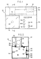
- Figure 1 is a front elevation showing an odor detector embodying the present invention;
- Figure 2 is a side elevation of the odor detector shown in Figure 1;
- Figure 3 is an exploded perspective view of the odor detector shown in Figures 1 and 2;
- Figure 4 is a simplified block diagram showing how the odor detector is brought to an initial zero setting using a computer; and
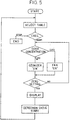
- Figure 5 is a flow diagram showing in more detail the manner of control shown in Figure 4.
- Referring now to the drawings, and particular to Figures 1, 2 and 3, there is illustrated an odor detector of the present invention generally designated by the
numeral 10. As shown, theodor detector 10 comprises asuitable housing 12 to house the several parts, to be detailed hereinafter. Thehousing 12 is provided with a hingeddoor 14 for access to atest compartment 16 defined in thehousing 12. Thedoor 14, when in the illustrated position, sealingly closes thetest compartment 16 to isolate it from the surrounding atmosphere. Preferably, thetest compartment 16 may be lined with stainless steel or other suitable anti-corrosive materials. Asensor 18 is provided on the ceiling of the test compartment away from thedoor 14. - In accordance with a preferred embodiment of the invention, the
sensor 18 comprises a simple substance of an n-type metal oxide semiconductor such as a sintered body of 99.999% pure tin oxide (SnO₂) containing Al₂O₃ as a binder. As an alternative, a 0.6 mm thick ceramic plate having a thin film of such a metal oxide deposited thereon by vacuum vapor deposition may be employed. A simple substance of n-type zinc oxide (ZnO) may also be used to form thesensor 18. Although not specifically shown, thesensor 18 has associated therewith a suitable electric heater for maintaining the sensor at a predetermined constant, operating temperature so that sensor readings may be independent of the temperature and humidity of the ambient air. Thesensor 18 may not be required to have the capability of discriminating various kinds of odors but is sufficient to be able to give an indication of the total concentration of such odors. A plurality of like sensors having their characteristic curves staggered by maintaining the respective sensors at different temperatures may be used in place of a single sensor. - As best seen in Figure 2, the
odor detector 10 includes an ozonizer in the form of anultraviolet lamp 20 which is provided on the back surface of thedoor 14. For this purpose, for example, an ultraviolet lamp manufactured under the designation of QGUL-11-65Z by Prince Electric Co., Japan, may be employed. In an alternate embodiment of the invention, it is possible to provide such an ultraviolet lamp outside thetest compartment 16 such that after completion of one detection cylcle, thesensor 18 may be removed from the compartment for exposure to the ultraviolet lamp outside thereof. Thetest compartment 16 is suitably formed to allow easy access for insertion and removal of an odor carrying object and is lined with stainless steel, as described above. The ceiling of thetest compartment 16 is formed near its center with a purging gas orair inlet port 22. Theair inlet port 22 is in communication with aventilation fan compartment 16 through a vertically disposedcylindrical conduit 26 and a horizontally disposedcylindrical conduit 28 which are coupled to each other in an air-tight manner. Although not shown in Figure 3 for clarity of illustration, aventilation fan 30 is provided in thecompartment 16 to draw the ambient air into the test compartment so as to purge it in the manner to be described later in more detail. Also, it is preferred that the vertically disposedconduit 26 includes a filter containing various absorbent materials such as activated charcoal, which are capable of irreversibly removing from the incoming air certain undesirable or interfering molecules. - The purging
air inlet port 22 has associated therewith afirst isolating valve 32 which, when closed, acts to prevent entry of the ambient air through theinlet port 22 into thetest compartment 16. In the illustrated embodiment, thefirst isolating valve 32 comprises a generallysquare plate 34 which normally is horizontally disposed so as to seal off the lower circumferential end of the vertically disposedconduit 26 that extends slightly downward from the ceiling of thetest compartment 16. Thesquare plate 34 has provided near its corners fourstuds 36 which extend through holes formed in the compartment ceiling in a manner to surround theair inlet port 22. A coiledspring 38 is provided on eachstud 36 between its head portion and the upper surface of the ceiling to normally biase thesquare plate 34 upwardly to close off theair inlet port 22. As best seen in Figure 3, anoperating link 40 is provided in a manner to connect the head portions of the twostuds 36 and is operatively associated with a horizontally disposedoperating rod 42 which forms a part of asolenoid device 44. Thesolenoid device 44, when actuated, acts to move the horizontally disposedoperating rod 42 downwardly, causing theoperating link 40 to move downwardly so as to move thesquare plate 34 away from sealing engagement with theair inlet port 22. - Referring back to Figure 2, the
test compartment 16 includes a purging gas orair outlet port 50 formed in the opposite inside surface to thedoor 14. Another horizontally disposedconduit 52 extends through thetest compartment 16 and the back surface of thehousing 12 to serve as theair outlet port 50. Theair outlet port 50 has associated therewith asecond isolating valve 54 which is similar in structure to thefirst isolating valve 32. A vertically disposedplate 56 is normally biased against the circumferential end of theconduit 52 by coiledsprings 58 on fourstuds 60 extending from theplate 56, in a manner to seal off theoutlet port 50. Anotheroperating link 62 is provided which connects the head portions of twoadjacent studs 60 and includes awire 64 having one end secured to theoperating link 62 at its midpoint. Twopulleys operating link 62 to thesolenoid device 44 by way of thewire 64. In this arrangement, thesolenoid device 44, when actuated, acts to pull thewire 64 upwardly, causing theoperating link 62 to move toward the back surface of thetest compartment 16 so that the vertically disposedplate 56 is moved away from sealing engagement with the circumferential end of theconduit 52 to open theoutlet port 50. It should be noted that, in the illustrated embodiment, the operations of theventilation fan 30, the first and second isolatingvalves test compartment 16 in an effective and efficient manner. - Referring back to Figure 1, the
housing 12 is provided with acontrol panel 70 which includes adisplay 72 for providing a digital reading of the electric current through thesensor 18 as an indication of the concentration of odors. Apower switch 74 is provided for a suitable power supply (not shown) which may be self-contained or supplied from an external power line (not shown). Also shown on thehousing 12 is a fan switch 76 which permits a selective activation of theventilation fan 30. A control knob 78 is provided to vary the magnitude of the voltage to be applied to thesensor 18. Another control knob 80 is provided just below the knob 78 to enable a zero adjustment of the digital reading ondisplay 72. Disposed above these control knobs is avoltmeter 82 for providing a reading of the voltage applied to the sensor. Aknob 84 for holding a peak value of the concentration of odors as detected is also provided on thecontrol panel 70. - Figure 4 is a block diagram showing the exemplary hardware for controlling the atmosphere in the
test compartment 16 so as to make theodor detector 10 ready to start a new detection cycle. As shown, the hardware includes acomputer 86 which may take the form of a personal computer or a mini-computer. Thecomputer 86 is coupled via an RS 232C cable to theozonizer 20 and theventilation fan 30 to receive therefrom electric signals indicative of the operational status of the ozonizer and the ventilation fan. The computer is also connected to aninterface 88 including relays R1 and R2 which are in turn connected to theozonizer 20 and theventilation fan 30, respectively. Command signals from thecomputer 86 will control the operations of the relays R1 and R2 which determine the operational status of the ozonizer and the ventilation fan. - In operation, the
power switch 74 is turned "ON" and then the control knob 78 is manually adjusted to provide a predetermined voltage to thesensor 18, with thedoor 14 closed. This will start heating the sensor to a predetermined, constant operating temperature. The next step is to determine that the sensor current on thedigital display 72 has become stable, which means that thesemiconductor sensor 18 is ready for operation so that the new detection cycle can start. The fan switch 76 is then actuated, which simultaneously causes the first and second isolatingvalves test compartment 16 to make the compartment odorless, enabling theodor detector 10 to be calibrated to a predetermined initial zero setting. Specifically, this calibration is accomplished by turning the control knob 80 for zero adjustment. It should be understood that it may not be necessary to purge thetest compartment 16 with the purging air prior to commencing a first detection cycle. In this case, the detection cycle can be started immediately after the zero adjustment of the odor concentration reading on thedigital display 72 is made. - Next, the
door 14 is opened to place a sample of odorant substances in thetest compartment 16, and thedoor 14 is closed to seal off the compartment. Gases carrying the odors start to fill the test compartment, coming into contact with thesemiconductor sensor 18. Adsorption of the odorant substances will occur on the semiconductor sensor, causing the sensor to undergo an electric resistance change. The changing resistance alters the electric current through the sensor, causing a corresponding variation in the digital reading on thedisplay 72. The peak value of the digital reading is proportional to the amount of adsorption taking place on the sensor, accordingly the total concentration of odors emitted from the sample. - Once the detection cycle has been completed, an operator gives a specific command to the
computer 86 to start the necessary procedure for bringing theodor detector 10 to the initial zero setting for subseqent detection. A flow chart of the steps performed by thecomputer 86 of Figure 4 is illustrated in Figure 5. As shown, the first step is to provide the start command to thecomputer 86, as described above. The next step is to select a specific table from among a plurality of tables stored in the computer memory (not shown), based on the identity and the peak concentration recorded from the previous detection cycle, the estimated rate of decrease of odor concentration toward the zero setting, the expected time interval between check points, the "ON" duration for theultraviolet lamp 20, the ON duration for theventilation fan 30, etc. Thecomputer 86 is programmed to execute a series of steps in accordance with the specific software stored in the memory so as to bring the odor concentration thetest compartment 16 to the zero setting by periodically comparing the concentration reading with that specified by the selected table at every check point to selectively operate theozonizer 20 and theventilation fan 30. A typical example of a table by reference to which the atmosphere in thetest compartment 16 is controlled into the zero setting is shown below:Odor Concentration Rate of Decrease Check Interval UV Lamp Duration Ventil. Fan Duration >1800 4(/sec.) 30(sec.) 30(sec.) >1600 4 30 30 >1400 4 30 30 >1200 4 30 30 >1000 4 30 30 > 800 4 30 30 > 600 4 30 30 > 400 4 30 30 > 200 4 30 30 > 100 4 30 30 > 50 4 30 30 > 20 4 20 20 0 4 20 20 <- 20 2 20 3(sec.) <-100 1 20 3 <-200 1 20 5 <-800 1 20 5 - As will be seen, the
ultraviolet lamp 20 is generally maintained in an "ON" condition until the odor concentration decreases to the zero setting. This is accomplished by causing the relay R1 to be kept energized in response to a computer command. The ultraviolet lamp acts as an ozonizer to neutralize the odors remaining in thetest compartment 16. If theultraviolet lamp 20 is kept "ON" too long, it has been found that the odor concentration decreases below the zero setting. When this occurs, thecomputer 86 automatically gives a command to theinterface 88 that causes the relay R2 to be energized to actuate theventilation fan 30. It has been found through experimentation that introducing the purging air will cause the odor concentration in the compartment to increase toward the zero setting. Once the odor concentration has been returned to the zero setting, it will be appreciated that theodor detector 10 is ready to perform the next detection cycle. - It should be understood that in accordance with the preferred embodiment of the present invention, the odor detector can be brought to the initial zero setting in a minimum of time. The use of the ozonizer and the ventillation fan which are selectively activated depending upon the current concentration of odors from the previously tested odorant substances will result in a remarkable reduction in the time required to bring the detector to the zero setting. Furthermore, computer control of the atmosphere in the test compartment using a plurality of stored tables will contribute greatly to a quick return to the zero setting, which will accommodate more detection cycles within a certain period of time. The following table shows comparative data between the odor detector of the invention and a typical detector of conventional type, regarding the time required to bring the detector to the zero setting after a detection cycle of four minutes during which a particular sample was placed in the test compartment.
Sample Time Required To Return To Zero Setting This Invention Conventional Type Soy Sauce 4 mins. 10 mins. Ground Coffee 6 mins. 8 mins. Adhesive 10 mins. 25 mins. Ethanol 10 mins. 50 mins. Aceton 10 mins. 60 mins. - As will be seen, the present invention can shorten the time required to bring the odor detector to the zero setting, by the factor of 3/4 to 1/6 as compared to the conventional detectors.
- Although the present invention has been described in terms of what are at present believed to be its preferred embodiments, it will be apparent to those skilled in the art that various changes may be made without departing from the scope of the invention. It is therefore intended that the appended claims cover such changes.
Claims (9)
- A method for detecting odors, comprising the steps of:
providing a test compartment (16) for accommodating odorant substances therein; providing an odor sensing means (18) in said test compartment, said odor sensing means having an electrical property responsive to odor molecules adsorbed onto said sensing means; detecting the electrical property of said sensing means prior to placing a first sample of odorant substances within said test compartment, for the purpose of using the detected property value for an initial zero setting; placing said first sample of odorant substances within said test compartment; detecting the electrical property of said sensing means relative to said initial zero setting as an indication of the total concentration of the odors emitting from said first sample of odorant substances; removing said first sample of odorant substances from said test compartment; contacting said sensing means with an ozone gas by allowing the gas to pass through said sensing means until the electrical property of said sensing means returns to said initial zero setting; contacting said sensing means with purging air rather than the ozone gas if the electrical property of said sensing means overshoots the initial zero setting, thereby causing the electrical property to converge into the initial zero setting; placing a second sample of odorant substances within said test compartment; and detecting the electrical property of said sensing means relative to said initial zero setting as an indication of the odors emitting from said second sample of odorant substances, whereby said ozone gas and said purging air contacting steps are selectively carried out by using a computer (86) which operates to cause the electrical property of said sensing means to converge into said initial zero setting by reference to a specific table which is selected by an operator from among a plurality of tables stored in the computer for quick return to said initial zero setting. - The method of claim 1 wherein said specific table is selected based on known factors including a peak concentration of said first sample, the estimated rate of decrease in the peak odor concentration toward the initial zero setting, the time during which said ozone gas is caused to contact the sensing means and the time during which said purging air is caused to contact the sensing means.
- The method of claim 2, further comprising the step of periodically comparing the sensed odor concentration with the peak concentration specified by said specific table to selectively carry out said ozone gas contacting step and said purging air contacting step on the basis of results of the comparison.
- The method of claim I wherein said sensing means (18) comprises an n-type semiconductor (18) having an electrical resistance responsive to odor molecules adsorbed thereonto.
- The method of claim I wherein said ozone gas is generated by an ultraviolet lamp (20).
- An apparatus (10) for the detection of odors, comprising: a test compartment (16) for accommodating odorant substances therein; an odor sensing means (18) disposed within said test compartment and having electrical property responsive to odor molecules adsorbed onto said sensing means; means (20) for generating an ozone gas in said test compartment and for allowing the generated ozone gas to pass through said sensing means so as to contact it until the electrical property of said sensing means returns to an initial zero setting; means (72) for detecting the electrical property of said sensing means relative to said initial zero setting as an indication of the odors emitting from said odorant substances; and a fan means (30) provided on said test compartment to draw a purging air into the compartment, said fan means being operable in response to the electrical property of said sensing means overshooting the initial zero setting, thereby causing the electrical property to converge into the initial zero setting, further comprising a computer means (86) for selectively actuating said ozone gas generating means and said fan means in such a manner as to cause the electrical property to converge into said initial zero setting, by reference to a specific table which is selected by an operator from among a plurality of tables stored in the computer means for quick return to said initial zero setting.
- The apparatus of claim 6 wherein said specific table is selected based on known factors including a peak concentration of said first sample, the estimated rate of decrease in the peak odor concentration toward the initial zero setting, the time during which said ozone gas is caused to contact the sensing means and the time during which said purging air is caused to contact the sensing means.
- The apparatus of claim 6 wherein said sensing means (18) comprises an n-type semiconductor (18) having electrical resistance responsive to odor molecules adsorbed thereonto.
- The apparatus of claim 6 wherein said ozone gas is generated by an ultraviolet lamp (20).
Applications Claiming Priority (2)
| Application Number | Priority Date | Filing Date | Title |
|---|---|---|---|
| JP1127694A JP2542259B2 (en) | 1989-05-19 | 1989-05-19 | Method and apparatus for measuring odor concentration |
| JP127694/89 | 1989-05-19 |
Publications (3)
| Publication Number | Publication Date |
|---|---|
| EP0398687A2 EP0398687A2 (en) | 1990-11-22 |
| EP0398687A3 EP0398687A3 (en) | 1991-02-06 |
| EP0398687B1 true EP0398687B1 (en) | 1996-05-08 |
Family
ID=14966393
Family Applications (1)
| Application Number | Title | Priority Date | Filing Date |
|---|---|---|---|
| EP90305294A Expired - Lifetime EP0398687B1 (en) | 1989-05-19 | 1990-05-16 | Method and apparatus for detecting odors |
Country Status (7)
| Country | Link |
|---|---|
| US (1) | US5090232A (en) |
| EP (1) | EP0398687B1 (en) |
| JP (1) | JP2542259B2 (en) |
| KR (1) | KR0163037B1 (en) |
| AU (1) | AU629934B2 (en) |
| CA (1) | CA2017207A1 (en) |
| DE (1) | DE69026862T2 (en) |
Families Citing this family (18)
| Publication number | Priority date | Publication date | Assignee | Title |
|---|---|---|---|---|
| JP2816870B2 (en) * | 1989-08-10 | 1998-10-27 | 能美防災株式会社 | Purging device for odor detection element |
| US5466605A (en) * | 1993-03-15 | 1995-11-14 | Arizona Board Of Regents | Method for detection of chemical components |
| FR2710153B1 (en) * | 1993-09-17 | 1995-12-01 | Alpha Mos Sa | Methods and apparatus for detecting odorous substances and applications. |
| US5985673A (en) * | 1994-12-22 | 1999-11-16 | Arizona Baord Of Regents | Method for regeneration of a sensor |
| US6282458B1 (en) | 1996-09-17 | 2001-08-28 | Ricoh Company, Ltd. | Methods and systems for controlling olfactory stimuli |
| JP3638201B2 (en) * | 1996-09-17 | 2005-04-13 | 株式会社リコー | Control type fragrance output device and fragrance sheet |
| FR2779826B1 (en) * | 1998-06-12 | 2002-05-31 | Europhtal | DETECTOR OF OZONE, NITROGEN DIOXIDE OR ANY OTHER POLLUTANT GAS AND USE THEREOF |
| JP4042232B2 (en) * | 1998-11-20 | 2008-02-06 | 株式会社島津製作所 | Gas measuring device |
| JP2004508570A (en) * | 2000-09-18 | 2004-03-18 | エレクトロ‐オプティクス リサーチ アンド デベロップメント リミテッド | Odor identification based on spectral markers |
| JP3912317B2 (en) * | 2002-05-28 | 2007-05-09 | ソニー株式会社 | Gas detector |
| US8053744B2 (en) * | 2009-04-13 | 2011-11-08 | Src, Inc. | Location analysis using nucleic acid-labeled tags |
| US8703493B2 (en) | 2010-06-15 | 2014-04-22 | Src, Inc. | Location analysis using fire retardant-protected nucleic acid-labeled tags |
| US8716027B2 (en) | 2010-08-03 | 2014-05-06 | Src, Inc. | Nucleic acid-labeled tags associated with odorant |
| EP2873971A1 (en) * | 2013-07-01 | 2015-05-20 | Universiti Putra Malaysia | An artificial olfactory system and an application thereof |
| US20160223549A1 (en) * | 2015-01-30 | 2016-08-04 | Toto Ltd. | Biological information measurement system |
| CN106290746B (en) * | 2016-10-31 | 2018-09-18 | 长虹美菱股份有限公司 | A kind of peculiar smell test box |
| IT201700093397A1 (en) * | 2017-08-11 | 2019-02-11 | Maselli Misure S P A | DEVICE AND METHOD FOR VERIFICATION OF A CO2 SENSOR |
| CN107632085B (en) * | 2017-09-11 | 2023-04-18 | 通标标准技术服务(上海)有限公司 | Device for dynamically simulating odor substance emission trend in whole vehicle environment and analysis method thereof |
Family Cites Families (10)
| Publication number | Priority date | Publication date | Assignee | Title |
|---|---|---|---|---|
| US3752748A (en) * | 1971-04-19 | 1973-08-14 | Mcmillan Electronics Corp | Ozone generating apparatus and method |
| US3776023A (en) * | 1971-12-22 | 1973-12-04 | Monitor Labs Inc | Calibration system for gas analyzers |
| US4244712A (en) * | 1979-03-05 | 1981-01-13 | Tongret Stewart R | Cleansing system using treated recirculating air |
| US4240799A (en) * | 1979-08-03 | 1980-12-23 | Energy For Independence, Inc. | Sensing the presence of ozone |
| US4563893A (en) * | 1983-04-22 | 1986-01-14 | Necmi Tanyolac | Methods and apparatus for detection and identification of volatile materials and odors |
| US4724008A (en) * | 1983-09-06 | 1988-02-09 | Arizona Instruments | Method for restoring the sensing capacity of an electrical sensor |
| JPS61131214A (en) * | 1984-11-30 | 1986-06-18 | Fujitsu Ltd | Magnetic head for floppy disk |
| US4770027A (en) * | 1986-03-24 | 1988-09-13 | Katuo Ehara | Method of measuring concentrations of odors and a device therefor |
| JPH01131444A (en) * | 1987-11-17 | 1989-05-24 | Katsuo Ebara | Smell discrimination device |
| JPH02208548A (en) * | 1989-02-09 | 1990-08-20 | Kirin Brewery Co Ltd | Method of zero-point return of smell sensor for detecting volatile component |
-
1989
- 1989-05-19 JP JP1127694A patent/JP2542259B2/en not_active Expired - Fee Related
-
1990
- 1990-02-09 KR KR1019900001590A patent/KR0163037B1/en not_active Expired - Fee Related
- 1990-05-16 DE DE69026862T patent/DE69026862T2/en not_active Expired - Fee Related
- 1990-05-16 US US07/523,809 patent/US5090232A/en not_active Expired - Lifetime
- 1990-05-16 EP EP90305294A patent/EP0398687B1/en not_active Expired - Lifetime
- 1990-05-18 CA CA002017207A patent/CA2017207A1/en not_active Abandoned
- 1990-05-21 AU AU55705/90A patent/AU629934B2/en not_active Ceased
Also Published As
| Publication number | Publication date |
|---|---|
| JP2542259B2 (en) | 1996-10-09 |
| KR900018667A (en) | 1990-12-22 |
| DE69026862T2 (en) | 1996-12-12 |
| US5090232A (en) | 1992-02-25 |
| AU629934B2 (en) | 1992-10-15 |
| JPH02306150A (en) | 1990-12-19 |
| EP0398687A2 (en) | 1990-11-22 |
| AU5570590A (en) | 1990-11-22 |
| CA2017207A1 (en) | 1990-11-19 |
| DE69026862D1 (en) | 1996-06-13 |
| KR0163037B1 (en) | 1999-05-01 |
| EP0398687A3 (en) | 1991-02-06 |
Similar Documents
| Publication | Publication Date | Title |
|---|---|---|
| US5090232A (en) | Method and apparatus for detecting odors | |
| EP0239233B1 (en) | A method of measuring concentrations of odors and a device therefor | |
| US4884435A (en) | Odor identifying apparatus and method | |
| US5801297A (en) | Methods and devices for the detection of odorous substances and applications | |
| US3925022A (en) | Detecting apparatus | |
| US4890478A (en) | Gas-in-oil monitoring apparatus and method | |
| US4327575A (en) | Monitoring apparatus and method for toxic vapors | |
| US6774613B1 (en) | Semiconductor gas sensor, gas sensor system and method of gas analysis | |
| WO2002063275A1 (en) | Apparatus and method of extracting volatime components | |
| US5014009A (en) | Detector for gas chromatograph for detecting ammonia and amine compounds | |
| WO1996006348A1 (en) | Discharge monitoring system | |
| US4166379A (en) | Apparatus for the detection of volatile organic substances | |
| Hofmann et al. | High resolution gas chromatography/selective odorant measurement by multisensor array (HRGC/SOMSA): a useful approach to standardise multisensor arrays for use in the detection of key food odorants | |
| JP3832073B2 (en) | Gas measuring device | |
| JP7819692B2 (en) | Gas detection method, information processing device, plant diagnostic method and plant diagnostic device | |
| JP2004012193A (en) | Gas identification detection method | |
| JP3367398B2 (en) | Odor measurement device | |
| JP4253971B2 (en) | Odor identification device | |
| GB2237880A (en) | Determining concentration of pollutant gas in an atmosphere | |
| KR101205032B1 (en) | Deodorization rate measuring system for fabrics | |
| EP1214590A1 (en) | Chemical sensing system | |
| US5689073A (en) | Verification circuit for a fluid handling analytical instrument | |
| JP2006064554A (en) | Odor measuring device and odor measuring method | |
| Matsuoka et al. | Development of quantitative odour supplier for plant leaf sensor system | |
| JP3395471B2 (en) | Trace organic matter analyzer |
Legal Events
| Date | Code | Title | Description |
|---|---|---|---|
| PUAI | Public reference made under article 153(3) epc to a published international application that has entered the european phase |
Free format text: ORIGINAL CODE: 0009012 |
|
| AK | Designated contracting states |
Kind code of ref document: A2 Designated state(s): DE FR GB IT NL |
|
| PUAL | Search report despatched |
Free format text: ORIGINAL CODE: 0009013 |
|
| AK | Designated contracting states |
Kind code of ref document: A3 Designated state(s): DE FR GB IT NL |
|
| 17P | Request for examination filed |
Effective date: 19910729 |
|
| 17Q | First examination report despatched |
Effective date: 19931207 |
|
| GRAA | (expected) grant |
Free format text: ORIGINAL CODE: 0009210 |
|
| AK | Designated contracting states |
Kind code of ref document: B1 Designated state(s): DE FR GB IT NL |
|
| REF | Corresponds to: |
Ref document number: 69026862 Country of ref document: DE Date of ref document: 19960613 |
|
| ET | Fr: translation filed | ||
| ITF | It: translation for a ep patent filed | ||
| PLBE | No opposition filed within time limit |
Free format text: ORIGINAL CODE: 0009261 |
|
| STAA | Information on the status of an ep patent application or granted ep patent |
Free format text: STATUS: NO OPPOSITION FILED WITHIN TIME LIMIT |
|
| 26N | No opposition filed | ||
| PGFP | Annual fee paid to national office [announced via postgrant information from national office to epo] |
Ref country code: FR Payment date: 19990504 Year of fee payment: 10 |
|
| PGFP | Annual fee paid to national office [announced via postgrant information from national office to epo] |
Ref country code: NL Payment date: 20000531 Year of fee payment: 11 |
|
| PG25 | Lapsed in a contracting state [announced via postgrant information from national office to epo] |
Ref country code: FR Free format text: LAPSE BECAUSE OF NON-PAYMENT OF DUE FEES Effective date: 20010131 |
|
| REG | Reference to a national code |
Ref country code: FR Ref legal event code: ST |
|
| PG25 | Lapsed in a contracting state [announced via postgrant information from national office to epo] |
Ref country code: NL Free format text: LAPSE BECAUSE OF NON-PAYMENT OF DUE FEES Effective date: 20011201 |
|
| REG | Reference to a national code |
Ref country code: GB Ref legal event code: IF02 |
|
| NLV4 | Nl: lapsed or anulled due to non-payment of the annual fee |
Effective date: 20011201 |
|
| PGFP | Annual fee paid to national office [announced via postgrant information from national office to epo] |
Ref country code: GB Payment date: 20020503 Year of fee payment: 13 |
|
| PGFP | Annual fee paid to national office [announced via postgrant information from national office to epo] |
Ref country code: DE Payment date: 20020715 Year of fee payment: 13 |
|
| PG25 | Lapsed in a contracting state [announced via postgrant information from national office to epo] |
Ref country code: GB Free format text: LAPSE BECAUSE OF NON-PAYMENT OF DUE FEES Effective date: 20030516 |
|
| PG25 | Lapsed in a contracting state [announced via postgrant information from national office to epo] |
Ref country code: DE Free format text: LAPSE BECAUSE OF NON-PAYMENT OF DUE FEES Effective date: 20031202 |
|
| GBPC | Gb: european patent ceased through non-payment of renewal fee |
Effective date: 20030516 |
|
| PG25 | Lapsed in a contracting state [announced via postgrant information from national office to epo] |
Ref country code: IT Free format text: LAPSE BECAUSE OF NON-PAYMENT OF DUE FEES;WARNING: LAPSES OF ITALIAN PATENTS WITH EFFECTIVE DATE BEFORE 2007 MAY HAVE OCCURRED AT ANY TIME BEFORE 2007. THE CORRECT EFFECTIVE DATE MAY BE DIFFERENT FROM THE ONE RECORDED. Effective date: 20050516 |