EP0394390B1 - Vehicle with multiple driven axles - Google Patents
Vehicle with multiple driven axles Download PDFInfo
- Publication number
- EP0394390B1 EP0394390B1 EP89910172A EP89910172A EP0394390B1 EP 0394390 B1 EP0394390 B1 EP 0394390B1 EP 89910172 A EP89910172 A EP 89910172A EP 89910172 A EP89910172 A EP 89910172A EP 0394390 B1 EP0394390 B1 EP 0394390B1
- Authority
- EP
- European Patent Office
- Prior art keywords
- locking means
- inter
- axle
- vehicle
- differential
- Prior art date
- Legal status (The legal status is an assumption and is not a legal conclusion. Google has not performed a legal analysis and makes no representation as to the accuracy of the status listed.)
- Expired - Lifetime
Links
Images

Classifications
-
- B—PERFORMING OPERATIONS; TRANSPORTING
- B60—VEHICLES IN GENERAL
- B60K—ARRANGEMENT OR MOUNTING OF PROPULSION UNITS OR OF TRANSMISSIONS IN VEHICLES; ARRANGEMENT OR MOUNTING OF PLURAL DIVERSE PRIME-MOVERS IN VEHICLES; AUXILIARY DRIVES FOR VEHICLES; INSTRUMENTATION OR DASHBOARDS FOR VEHICLES; ARRANGEMENTS IN CONNECTION WITH COOLING, AIR INTAKE, GAS EXHAUST OR FUEL SUPPLY OF PROPULSION UNITS IN VEHICLES
- B60K17/00—Arrangement or mounting of transmissions in vehicles
- B60K17/34—Arrangement or mounting of transmissions in vehicles for driving both front and rear wheels, e.g. four wheel drive vehicles
- B60K17/344—Arrangement or mounting of transmissions in vehicles for driving both front and rear wheels, e.g. four wheel drive vehicles having a transfer gear
- B60K17/346—Arrangement or mounting of transmissions in vehicles for driving both front and rear wheels, e.g. four wheel drive vehicles having a transfer gear the transfer gear being a differential gear
-
- B—PERFORMING OPERATIONS; TRANSPORTING
- B60—VEHICLES IN GENERAL
- B60K—ARRANGEMENT OR MOUNTING OF PROPULSION UNITS OR OF TRANSMISSIONS IN VEHICLES; ARRANGEMENT OR MOUNTING OF PLURAL DIVERSE PRIME-MOVERS IN VEHICLES; AUXILIARY DRIVES FOR VEHICLES; INSTRUMENTATION OR DASHBOARDS FOR VEHICLES; ARRANGEMENTS IN CONNECTION WITH COOLING, AIR INTAKE, GAS EXHAUST OR FUEL SUPPLY OF PROPULSION UNITS IN VEHICLES
- B60K23/00—Arrangement or mounting of control devices for vehicle transmissions, or parts thereof, not otherwise provided for
- B60K23/08—Arrangement or mounting of control devices for vehicle transmissions, or parts thereof, not otherwise provided for for changing number of driven wheels, for switching from driving one axle to driving two or more axles
- B60K23/0808—Arrangement or mounting of control devices for vehicle transmissions, or parts thereof, not otherwise provided for for changing number of driven wheels, for switching from driving one axle to driving two or more axles for varying torque distribution between driven axles, e.g. by transfer clutch
Definitions
- This invention relates to vehicles with multiple driven axles and particularly to agricultural and industrial tractors with front and rear driven axles.
- Such tractors conventionally have a clutch for connecting and disconnecting drive to the front axle to switch between two and four wheel drive.
- This clutch is necessary since it is essential to disconnect drive to the front wheels in certain operating conditions, for example, when the tractor is being driven at speed on a road in order to prevent excessive wear to the tyres due to unequal peripheral tyre speed.
- a vehicle having front and rear drive axles driven from a prime mover via an inter-axle differential, locking means for locking up the inter-axle differential and an actuating means for the locking means, the vehicle being characterised in that it also has independently operable left and right brakes on the rear axle, a control system for the actuating means and sensors to sense when the rear axle brakes are applied, the control system being arranged, in response to signals from the sensors, indicating that both rear axle brakes are being applied simultaneously, to cause the actuating means to engage the locking means.
- control system will be arranged not to engage the locking means if only one brake is applied to turn the tractor.
- an operator control is provided to allow a vehicle operator to override the control means to engage or disengage the locking means when he determines that the operating conditions so require.
- the inter-axle differential will be of the unequal torque split type in which the torque distribution to the front and rear axles reflects the weight distribution.
- the control system preferably operates automatically to engage the locking means of the inter-axle differential when the links are in their lowered work position and to disengage the locking means when the links are raised to their transport position.
- the control system also preferably operates to disengage automatically the locking means when the vehicle is travelling above a preselected speed.
- a speed of the order of 14 k.p.h. has been found an appropriate preselected speed for tractors.
- inter-wheel differentials may also be provided with its own locking means which may be arranged to operate in unison with the inter-axle differential locking means under the control of the same control system.
- the actuating means for the locking means of the inter-axle differential may include spring means to bias the locking means into its engaged condition so that the locking means is automatically engaged should any failure occur in the control system or the actuating system.
- this shows a tractor in which an engine E drives a front axle (represented by a crown wheel and pinion 10) and a rear axle (represented by a crown wheel and pinion 11) via an inter-axle differential 12, a gearbox G and a main drive clutch C.
- Each axle carries ground engaging wheels (not shown) with tyres.
- the tractor is provided with right and left hand separately operable brakes (indicated schematically at 40) associated with the right and left hand sides of the rear axle of the tractor.
- these brakes are operated by independent right and left brake pedals (not shown) to allow the application of one brake only in order to facilitate turning of the tractor.
- these two brake pedals are connected so that both right and left rear axle brakes must be applied simultaneously.
- the tractor is also provided with conventional rear implement attachment links (not shown).
- the inter-axle differential 12 comprises an input sun gear 13 driven from a gearbox output shaft 14, an output sun gear 15, orbiting compound planet gears 16, meshing with sun gears 13 and 15 and a planet gear carrier 17, which carries a front axle drive gear 18 which meshes with a gear 19 on a front axle drive shaft 20.
- Drive to the rear crown wheel and pinion 11 is via a shaft 21 connected with output sun gear 15.
- the inter-axle differential gear 12 also includes a locking means in the form of a dog clutch member 22, which is axially slidable on splines 21a on shaft 21 and has teeth 23 engageable with corresponding dog teeth 24 formed on planet carrier 17.
- a locking means in the form of a dog clutch member 22, which is axially slidable on splines 21a on shaft 21 and has teeth 23 engageable with corresponding dog teeth 24 formed on planet carrier 17.
- the sun gear 15 is in fact locked against rotation relative to the planet carrier 17 so that the entire inter-axle differential 12 rotates as a single unit, thus providing a rigid drive connection between shafts 14, 21 and 20.
- the teeth 23 and 24 are arranged to be biased into engagement by a spring 25 which acts on the clutch member 22 via a lever 26.
- the inter-axle differential is disengaged by the application of fluid under pressure to an actuator 27 acting on lever 26.
- the actuator 27 may be, for example, hydraulically or pneumatically operated.
- the actuator 27 is supplied with pressurised hydraulic fluid by a pump 28 via a solenoid operated control valve 29.
- a pressure relief valve 39 controls the level of hydraulic pressure in the pump circuit.
- Control valve 29 it itself controlled by an electronic control syszem CS shown diagramatically in Figure 1 whose control criteria are discussed below. If any failure occurs in actuator 27 or the associated hydraulic or electrical circuitry the teeth 23 and 24 are automatically engaged by spring 25.
- the tractor is also provided with an operator controlled press button B, which is of the push-on push-off type which allows the operator to override the control system CS to engage or disengage the inter-axle differential lock when he judges that the operating conditions of the tractor require him to intervene.
- An indicator light L is also provided to indicate to the operator when the inter-axle differential lock is engaged.
- the Control System In addition to the input from switch B, the Control System also receives inputs from various sensors 30, 31, 32, 33, etc. which indicate various operating parameters of the tractor such as right and left brake application (sensors 30 and 31), tractor forward speed (sensor 32) and the position of the tractor implement attachment links (sensor 33). Since the actual constructional details of sensors 30, 31, 32, 33, etc. form no part of the present invention, no further details of these sensors will be give:.. Any one of the many well-known sensors capable of sensing each parameter may be used.
- the control system CS controls the inter-axle differential locking means in accordance with the following criteria.
- the actuator 27 When the implement attachment links are in their working positions (sensed by sensor 33) the actuator 27 is again depressurised to engage the differential lock since under these working conditions it is desirable to lock the differential action between front and rear axle drive shaft 20 and 21 to prevent excessive wheelslip in bad ground conditions.
- the actuator 27 When the implement attachment links are raised to their transport condition (again sensed by sensor 33) indicating that the implement is now no longer in actual use, the actuator 27 is pressurised to disengage the differential locking means.
- actuator 27 is arranged to be pressurised if it is not already in this condition to prevent excessive tyre wear due to possible unequal peripheral tyre speed of the front and rear wheels which might arise if no differential action is allowed between the front and rear drive shafts 20 and 21.
- the front and rear axles have their own inter-wheel differentials provided by the crown wheel and pinion assemblies 10 and 11 respectively.
- One or both of these inter-wheel differentials may be provided with a locking means controlled in unison with the locking means of the inter-axle differential 12 by the control system CS.
- the inter-axle differential 12 is arranged to provide an unequal torque split to the front and rear crown wheel and pinion assemblies 10 and 11 respectively.
- This torque split is arranged to reflect the relative weight distribution on the front and rear axle.
- the torque split may be 30-70 in favour of the rear axle.
- control system CS may be arranged to ensure depressurisation of actuator 27 at slip levels above a preset limit (say 15% slip) to engage the locking means of the inter-axle differential 12 and the inter-wheel differentials 10 and 11.
- control system of the present invention may be integrated into a larger control system controlling other parts of thi vehicle, such as that provided on the previously mentioned Massey-Ferguson "Datatronic" tractors.
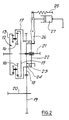
- Figure 2 shows an alternative inter-axle differential arrangement in which components of a similar function to those shown in Figure 1 have been similarly numbered.
- the input gear 13 to the inter-axle differential is increased in diameter and is internally toothed to engage the planet gears 16 externally as is the output gear 15.
- This alternative gear arrangement is designed to minimise the loading on the teeth of the differential gear elements by maximising the radius of gears 13 and 15 respectively. It must be remembered here that that space available for fitting the inter-axle differential 12 is often limited by the close proximity of other parts of the tractor and the use of this alternative gear arrangement maximises the radius of gears 13 and 15 within the available space.
Landscapes
- Engineering & Computer Science (AREA)
- Chemical & Material Sciences (AREA)
- Combustion & Propulsion (AREA)
- Transportation (AREA)
- Mechanical Engineering (AREA)
- Arrangement And Driving Of Transmission Devices (AREA)
- Arrangement And Mounting Of Devices That Control Transmission Of Motive Force (AREA)
Abstract
Description
- This invention relates to vehicles with multiple driven axles and particularly to agricultural and industrial tractors with front and rear driven axles.
- Such tractors conventionally have a clutch for connecting and disconnecting drive to the front axle to switch between two and four wheel drive. This clutch is necessary since it is essential to disconnect drive to the front wheels in certain operating conditions, for example, when the tractor is being driven at speed on a road in order to prevent excessive wear to the tyres due to unequal peripheral tyre speed.
- It is also necessary to dis-engage the clutch when the tractor is required to turn very sharply. In these circumstances, the front wheels have to travel appreciably faster than the rear wheels and the turn is impeded if the front wheels are mechanically driven at the same peripheral speed as the rear wheels.
- It is well know on four wheel drive highway vehicles to use a differential between the front and rear axles, thus eliminating the excess tyre wear at high speed and the restriction of sharp turns. However, this system is unsatisfactory on a tractor due to the normal variation in front/rear weight distribution, which can vary between 80/20 and 20/80.
- It is also known to be advantageous in a tractor provided with rear axle brakes only, to ensure that drive to the front wheels is directly connected to the rear wheels whenever such a tractor is braked in order to ensure that both front and rear axles can contribute to the braking effect via their contact with the ground.
- Various systems have therefore been proposed which, for example, take account of the requirement to disconnect front wheel drive at speed on the road and which ensure that when both rear axle brakes are applied, drive is automatically connected to the front axle.
- Other systems have been proposed which change the gear ratio between the front and rear axles when the tractor is turning sharply; this causes the peripheral speed of the front wheels to increase relative to the rear wheels so that the front wheel drive aids rather than impedes the sharpness of the turn.
- It is an object of the present invention to provide a vehicle with multiple driven axles which takes account of the operating conditions of an agricultural or industrial tractor and which obviates the need for a clutch to connect or disconnect drive to the front axle and for an inter-axle ratio changing device to facilitate sharp turns, as discussed above.
- Thus according to the present invention, there is provided a vehicle having front and rear drive axles driven from a prime mover via an inter-axle differential, locking means for locking up the inter-axle differential and an actuating means for the locking means, the vehicle being characterised in that it also has independently operable left and right brakes on the rear axle, a control system for the actuating means and sensors to sense when the rear axle brakes are applied, the control system being arranged, in response to signals from the sensors, indicating that both rear axle brakes are being applied simultaneously, to cause the actuating means to engage the locking means.
- If the vehicle is a tractor with independently operable left and right brakes, the control system will be arranged not to engage the locking means if only one brake is applied to turn the tractor.
- Preferably an operator control is provided to allow a vehicle operator to override the control means to engage or disengage the locking means when he determines that the operating conditions so require.
- Preferably in a vehicle such as a tractor, in which the front to rear axle weight distribution is unequal, the inter-axle differential will be of the unequal torque split type in which the torque distribution to the front and rear axles reflects the weight distribution.
- If the vehicle is a tractor with implement attachment links movable between a lowered work position and a raised transport position, the control system preferably operates automatically to engage the locking means of the inter-axle differential when the links are in their lowered work position and to disengage the locking means when the links are raised to their transport position.
- The control system also preferably operates to disengage automatically the locking means when the vehicle is travelling above a preselected speed. A speed of the order of 14 k.p.h. has been found an appropriate preselected speed for tractors.
- If the vehicle has an inter-wheel differential on each axle at least one of these inter-wheel differentials may also be provided with its own locking means which may be arranged to operate in unison with the inter-axle differential locking means under the control of the same control system.
- The actuating means for the locking means of the inter-axle differential may include spring means to bias the locking means into its engaged condition so that the locking means is automatically engaged should any failure occur in the control system or the actuating system.
- One embodiment of the present invention will now be described, by way of example only, with reference to the accompanying drawings in which:
- Figure 1 is a schematic representation of a tractor embodying an inter-axle differential lock control arrangement in accordance with the present invention, and
- Figure 2 is a schematic representation of an alternative inter-axle differential arrangement for use in the tractor of Figure 1.
- Referring to Figure 1, this shows a tractor in which an engine E drives a front axle (represented by a crown wheel and pinion 10) and a rear axle (represented by a crown wheel and pinion 11) via an
inter-axle differential 12, a gearbox G and a main drive clutch C. Each axle carries ground engaging wheels (not shown) with tyres. - The tractor is provided with right and left hand separately operable brakes (indicated schematically at 40) associated with the right and left hand sides of the rear axle of the tractor. In the conventional manner these brakes are operated by independent right and left brake pedals (not shown) to allow the application of one brake only in order to facilitate turning of the tractor. As is normal for road use of the tractor, these two brake pedals are connected so that both right and left rear axle brakes must be applied simultaneously.
- The tractor is also provided with conventional rear implement attachment links (not shown).
- The
inter-axle differential 12 comprises aninput sun gear 13 driven from agearbox output shaft 14, anoutput sun gear 15, orbitingcompound planet gears 16, meshing withsun gears planet gear carrier 17, which carries a frontaxle drive gear 18 which meshes with agear 19 on a frontaxle drive shaft 20. Drive to the rear crown wheel andpinion 11 is via ashaft 21 connected withoutput sun gear 15. - The inter-axle
differential gear 12 also includes a locking means in the form of adog clutch member 22, which is axially slidable onsplines 21a onshaft 21 and hasteeth 23 engageable withcorresponding dog teeth 24 formed onplanet carrier 17. As will be appreciated when theteeth sun gear 15 is in fact locked against rotation relative to theplanet carrier 17 so that the entireinter-axle differential 12 rotates as a single unit, thus providing a rigid drive connection betweenshafts - The
teeth spring 25 which acts on theclutch member 22 via alever 26. The inter-axle differential is disengaged by the application of fluid under pressure to anactuator 27 acting onlever 26. Theactuator 27 may be, for example, hydraulically or pneumatically operated. - In the illustrated example, the
actuator 27 is supplied with pressurised hydraulic fluid by apump 28 via a solenoid operatedcontrol valve 29. Apressure relief valve 39 controls the level of hydraulic pressure in the pump circuit.Control valve 29 it itself controlled by an electronic control syszem CS shown diagramatically in Figure 1 whose control criteria are discussed below. If any failure occurs inactuator 27 or the associated hydraulic or electrical circuitry theteeth spring 25. - The tractor is also provided with an operator controlled press button B, which is of the push-on push-off type which allows the operator to override the control system CS to engage or disengage the inter-axle differential lock when he judges that the operating conditions of the tractor require him to intervene. An indicator light L is also provided to indicate to the operator when the inter-axle differential lock is engaged.
- In addition to the input from switch B, the Control System also receives inputs from
various sensors sensors 30 and 31), tractor forward speed (sensor 32) and the position of the tractor implement attachment links (sensor 33). Since the actual constructional details ofsensors - The control system CS controls the inter-axle differential locking means in accordance with the following criteria.
- When the engine E is started up the
actuator 27 is depressurised, thus allowingspring 25 to engage thedifferential lock - As previously indicated, whenever the operator control button B is pressed this enables the tractor operator to override the command currently being issued by the control system CS if he feels that an override is necessary.
- Whenever both left and right hand rear axle brakes are applied simultaneously (sensed by
sensors 30 and 31) theactuator 27 is again depressurised to engage thedifferential lock pinion assemblies actuator 27. - When the implement attachment links are in their working positions (sensed by sensor 33) the
actuator 27 is again depressurised to engage the differential lock since under these working conditions it is desirable to lock the differential action between front and rearaxle drive shaft actuator 27 is pressurised to disengage the differential locking means. - Additionally, if the tractor is travelling above a preselected speed of say 14 k.p.h (sensed by sensor 32),
actuator 27 is arranged to be pressurised if it is not already in this condition to prevent excessive tyre wear due to possible unequal peripheral tyre speed of the front and rear wheels which might arise if no differential action is allowed between the front andrear drive shafts - As will be appreciated in the described tractor application, the front and rear axles have their own inter-wheel differentials provided by the crown wheel and
pinion assemblies inter-axle differential 12 by the control system CS. - In a vehicle such as a tractor, the weight distribution between the front and rear axles is normally far from equal with the majority of the weight being taken on the rear axle. In these circumstances, the
inter-axle differential 12 is arranged to provide an unequal torque split to the front and rear crown wheel andpinion assemblies - If the tractor is fitted with a means for determining wheel slip relative to the ground (as for example provided on the Massey-Ferguson "Datatronic" tractors), the control system CS may be arranged to ensure depressurisation of
actuator 27 at slip levels above a preset limit (say 15% slip) to engage the locking means of theinter-axle differential 12 and theinter-wheel differentials - As will be appreciated, not all the above control criteria need be employed in any one system and the most basic system need only employ the brake application criteria.
- Also the control system of the present invention may be integrated into a larger control system controlling other parts of thi vehicle, such as that provided on the previously mentioned Massey-Ferguson "Datatronic" tractors.
- Figure 2 shows an alternative inter-axle differential arrangement in which components of a similar function to those shown in Figure 1 have been similarly numbered. As tan be seen from Figure 2, the
input gear 13 to the inter-axle differential is increased in diameter and is internally toothed to engage theplanet gears 16 externally as is theoutput gear 15. This alternative gear arrangement is designed to minimise the loading on the teeth of the differential gear elements by maximising the radius ofgears gears
Claims (9)
- A vehicle having front and rear drive axles (10, 11) driven from a prime mover (E) via an inter-axle differential (12), locking means (22, 23, 24) for locking up the inter-axle differential (12) and an actuating means (25, 26, 27, 29) for the locking means, the vehicle being characterised in that it also has independently operable left and right brakes on the rear axle, a control system (CS) for the actuating means and sensors (30, 31) to sense when the rear axle brakes are applied, the control system being arranged, in response to signals from the sensors, indicating that both rear axle brakes are being applied simultaneously, to cause the actuating means to engage the locking means.
- A vehicle according to Claim 1 characterised by the provision of an operator control (B) to allow a vehicle operator to override the control system (CS) to engage or disengage the locking means (22, 23, 24) when he determines that the operating conditions so require.
- A vehicle according to Claim 1 or Claim 2 characterised in that the control system (CS) initiates automatic disengagement of the locking means (22, 23, 24) when the vehicle is travelling above a preselected speed.
- A vehicle according to any one of Claims 1 to 3 having an interwheel differential on each axle, the vehicle being characterised in that at least one of said inter-wheel differentials is provided with its own locking means which is arranged to operate in unison with the inter-axle differential locking means (22, 23, 24) under the control of the same control system (CS).
- A vehicle according to any one of Claims 1 to 4 in which the front to rear axle weight distribution is unequal, the vehicle being characterised in that the inter-axle differential (12) is of an unequal torque split type (13, 15, 16, It) in which the torque distribution to the front and rear axles (10, 11) reflects the weight distribution.
- A vehicle according to any one of Claims 1 to 5 characterised in that the actuating means (25, 26, 27, 29) for the locking means (22, 23, 24) of the inter-axle differential (12) includes spring means (25) to bias the locking means into its engaged condition so that the locking means is automatically engaged should any failure occur in the control system (CS) or the actuating system (25, 26, 27, 29).
- A vehicle according to any one of Claims 1 to 6 in the form of a tractor with implement attachment links movable between a lowered work position and a raised transport position, the vehicle being characterised in that the control system (CS) automatically engages the locking means (22, 23, 24) of the inter-axle differential (12) when the links are in their lowered work position and disengages the locking means when the links are raised to their transport position.
- A vehicle according to any one of Claims 1 to 7 characterised in that the inter-axle differential (12) comprises two sun gears (13, 15) engaged by compound planet gears (16) mounted on a carrier (17), one (13) of the sun gears acting as the input member of the differential from the prime mover (E) and the other sun gear (15) and the carrier (17) acting as the outputs from the differential to the two drive axles (10, 11).
- A vehicle according to Claim 8 characterised in that the two sun gears (13, 15 Figure 2) extend radially outward of the planet gears (16) and are internally toothed to engage the planet gears externally thus minimising the tooth loading on the sun and planet gears.
Applications Claiming Priority (2)
| Application Number | Priority Date | Filing Date | Title |
|---|---|---|---|
| GB8819325 | 1988-08-13 | ||
| GB888819325A GB8819325D0 (en) | 1988-08-13 | 1988-08-13 | Vehicle with multiple driven axles |
Publications (2)
| Publication Number | Publication Date |
|---|---|
| EP0394390A1 EP0394390A1 (en) | 1990-10-31 |
| EP0394390B1 true EP0394390B1 (en) | 1992-12-23 |
Family
ID=10642126
Family Applications (1)
| Application Number | Title | Priority Date | Filing Date |
|---|---|---|---|
| EP89910172A Expired - Lifetime EP0394390B1 (en) | 1988-08-13 | 1989-08-14 | Vehicle with multiple driven axles |
Country Status (4)
| Country | Link |
|---|---|
| US (1) | US5054573A (en) |
| EP (1) | EP0394390B1 (en) |
| GB (2) | GB8819325D0 (en) |
| WO (1) | WO1990001430A1 (en) |
Families Citing this family (16)
| Publication number | Priority date | Publication date | Assignee | Title |
|---|---|---|---|---|
| JP2652709B2 (en) * | 1989-07-29 | 1997-09-10 | 富士重工業株式会社 | 4-wheel drive vehicle with center differential device |
| US5802489A (en) * | 1994-11-14 | 1998-09-01 | Case Corporation | Front wheel drive engagement control system for agricultural vehicles |
| JP2002172951A (en) * | 2000-12-07 | 2002-06-18 | Yamaha Motor Co Ltd | Vehicle differential lock device |
| US7438147B2 (en) | 2003-04-02 | 2008-10-21 | Yamaha Hatsudoki Kabushiki Kaisha | Transmission for off-road vehicle |
| US7287619B2 (en) * | 2003-04-02 | 2007-10-30 | Yamaha Hatsudoki Kabushiki Kaisha | Air intake system for off-road vehicle |
| US7510199B2 (en) | 2003-04-02 | 2009-03-31 | Yamaha Hatsudoki Kabushiki Kaisha | Off-road vehicle with wheel suspension |
| US7506712B2 (en) | 2003-04-02 | 2009-03-24 | Yamaha Hatsudoki Kabushiki Kaisha | Off road vehicle with air intake system |
| US7367417B2 (en) | 2003-04-02 | 2008-05-06 | Yamaha Hatsudoki Kabushiki Kaisha | Floor arrangement for off-road vehicle |
| US7650959B2 (en) | 2003-04-02 | 2010-01-26 | Yamaha Hatsudoki Kabushiki Kaisha | Frame arrangement for off-road vehicle |
| US7147076B2 (en) * | 2003-04-02 | 2006-12-12 | Yamaha Hatsudoki Kabushiki Kaisha | Drive system for off-road vehicle |
| US7357211B2 (en) | 2003-04-02 | 2008-04-15 | Yamaha Hatsudoki Kabushiki Kaisha | Steering system for off-road vehicle |
| US6976553B1 (en) | 2004-02-19 | 2005-12-20 | Polaris Industries Inc. | Multimodal vehicle traction system |
| GB2414217B (en) * | 2004-05-21 | 2007-08-01 | Ford Global Tech Llc | Vehicle differential control |
| US20070292068A1 (en) * | 2006-05-31 | 2007-12-20 | Jody Mayne | Free-wheel drive mechanism |
| US8544588B2 (en) * | 2007-11-09 | 2013-10-01 | Ford Global Technologies, Llc | Power takeoff for all-wheel-drive systems |
| US9429220B2 (en) | 2013-03-15 | 2016-08-30 | Brandt Road Rail Corporation | Vehicle differential lock disengagement bypass |
Family Cites Families (11)
| Publication number | Priority date | Publication date | Assignee | Title |
|---|---|---|---|---|
| DE301537C (en) * | ||||
| US1341223A (en) * | 1916-08-28 | 1920-05-25 | Thomas Foreign Patents Ltd | Transmission of power |
| AT355920B (en) * | 1978-05-08 | 1980-03-25 | Schreiner Joachim | STEERING GEARBOX FOR TRACKED VEHICLES |
| DE3015379A1 (en) * | 1980-04-22 | 1981-10-29 | Audi Nsu Auto Union Ag, 7107 Neckarsulm | Brake control for four-wheel drive transmission - has equalising gear drive to lock front and rear drives during braking |
| JPS59154427U (en) * | 1983-04-01 | 1984-10-17 | 日産自動車株式会社 | 4 wheel drive vehicle |
| JPS59184027A (en) * | 1983-04-04 | 1984-10-19 | Nissan Motor Co Ltd | Four-wheel-drive vehicle |
| DE3313823A1 (en) * | 1983-04-16 | 1984-10-18 | Faun-Werke Kommunalfahrzeuge und Lastkraftwagen Karl Schmidt, 8500 Nürnberg | DRIVE FOR A MOTOR VEHICLE, ESPECIALLY A COMMERCIAL VEHICLE, WITH AT LEAST ONE LOCKING DIFFERENTIAL |
| DE3643831A1 (en) * | 1986-12-20 | 1988-07-07 | Deere & Co | DRIVE SYSTEM FOR THE WHEELS OF TWO WHEEL COUPLES |
| JP2572064B2 (en) * | 1987-04-27 | 1997-01-16 | マツダ株式会社 | Operating device for four-wheel drive vehicles |
| GB8715759D0 (en) * | 1987-07-03 | 1987-08-12 | Drew M J | Selecting 4-wheel drive farm tractor |
| US4811811A (en) * | 1988-02-16 | 1989-03-14 | Deere & Company | Brake system for four-wheel drive vehicles |
-
1988
- 1988-08-13 GB GB888819325A patent/GB8819325D0/en active Pending
-
1989
- 1989-08-14 GB GB8918461A patent/GB2223284B/en not_active Revoked
- 1989-08-14 WO PCT/GB1989/000948 patent/WO1990001430A1/en not_active Ceased
- 1989-08-14 EP EP89910172A patent/EP0394390B1/en not_active Expired - Lifetime
- 1989-08-14 US US07/469,411 patent/US5054573A/en not_active Expired - Lifetime
Also Published As
| Publication number | Publication date |
|---|---|
| US5054573A (en) | 1991-10-08 |
| GB2223284A (en) | 1990-04-04 |
| GB2223284B (en) | 1992-05-13 |
| WO1990001430A1 (en) | 1990-02-22 |
| EP0394390A1 (en) | 1990-10-31 |
| GB8819325D0 (en) | 1988-09-14 |
| GB8918461D0 (en) | 1989-09-20 |
Similar Documents
| Publication | Publication Date | Title |
|---|---|---|
| US5054573A (en) | Vehicle with multiple driven axles | |
| US6085138A (en) | Differential lock control system | |
| US4050534A (en) | Drive axle system useable in 6 × 6 vehicle | |
| US5505267A (en) | Differential lock control system for agricultural vehicles | |
| EP0217087B1 (en) | Brake control system for four-wheel drive vehicle | |
| US5301769A (en) | Vehicle power distribution and control system | |
| US5802489A (en) | Front wheel drive engagement control system for agricultural vehicles | |
| US6554731B2 (en) | On-demand transfer case with synchronized range shift and adaptive clutch control | |
| US4669559A (en) | Four-wheel driven vehicles | |
| US5125490A (en) | Center differential lock mechanism controlling device | |
| US5161636A (en) | All-wheel drive tractor | |
| GB2058274A (en) | Controlling transfer clutch in four-wheel drive vehicle | |
| US5443429A (en) | Automatic powershifting transfer case for a vehicle | |
| GB2140104A (en) | Drive for a motor vehicle having at least one locking differential | |
| US6199653B1 (en) | Four-wheel driven vehicle | |
| GB2058273A (en) | Controlling transfer clutch in four-wheel drive vehicle | |
| DE102009000452B4 (en) | working vehicle | |
| US5044458A (en) | Drive engagement for a selectively engageable wheelset | |
| US7291094B2 (en) | Driving system for off-road utility vehicle | |
| EP0112421B1 (en) | Four-wheel drive vehicle | |
| US5323890A (en) | Transmission assembly for working vehicles | |
| JPH10264788A (en) | Work vehicle shift control device | |
| EP0246884B1 (en) | Power transmission system for a four-wheel drive vehicle | |
| JPS601030A (en) | Drive force transmission for four wheel drive car | |
| EP0457742B1 (en) | Method and arrangement for automatic switching on/off of the power transmission of a driving front axle of a tractor or working machine |
Legal Events
| Date | Code | Title | Description |
|---|---|---|---|
| PUAI | Public reference made under article 153(3) epc to a published international application that has entered the european phase |
Free format text: ORIGINAL CODE: 0009012 |
|
| 17P | Request for examination filed |
Effective date: 19900615 |
|
| AK | Designated contracting states |
Kind code of ref document: A1 Designated state(s): DE FR GB IT |
|
| 17Q | First examination report despatched |
Effective date: 19920113 |
|
| GRAA | (expected) grant |
Free format text: ORIGINAL CODE: 0009210 |
|
| AK | Designated contracting states |
Kind code of ref document: B1 Designated state(s): DE FR GB IT |
|
| PG25 | Lapsed in a contracting state [announced via postgrant information from national office to epo] |
Ref country code: IT Free format text: LAPSE BECAUSE OF FAILURE TO SUBMIT A TRANSLATION OF THE DESCRIPTION OR TO PAY THE FEE WITHIN THE PRE;WARNING: LAPSES OF ITALIAN PATENTS WITH EFFECTIVE DATE BEFORE 2007 MAY HAVE OCCURRED AT ANY TIME BEFORE 2007. THE CORRECT EFFECTIVE DATE MAY BE DIFFERENT FROM THE ONE RECORDED.SCRIBED TIME-LIMIT Effective date: 19921223 |
|
| RAP2 | Party data changed (patent owner data changed or rights of a patent transferred) |
Owner name: MASSEY-FERGUSON MANUFACTURING LIMITED |
|
| REF | Corresponds to: |
Ref document number: 68904068 Country of ref document: DE Date of ref document: 19930204 |
|
| ET | Fr: translation filed | ||
| PLBE | No opposition filed within time limit |
Free format text: ORIGINAL CODE: 0009261 |
|
| STAA | Information on the status of an ep patent application or granted ep patent |
Free format text: STATUS: NO OPPOSITION FILED WITHIN TIME LIMIT |
|
| 26N | No opposition filed | ||
| REG | Reference to a national code |
Ref country code: GB Ref legal event code: 732E |
|
| REG | Reference to a national code |
Ref country code: FR Ref legal event code: TP |
|
| REG | Reference to a national code |
Ref country code: FR Ref legal event code: CD |
|
| REG | Reference to a national code |
Ref country code: GB Ref legal event code: IF02 |
|
| REG | Reference to a national code |
Ref country code: GB Ref legal event code: 732E |
|
| PGFP | Annual fee paid to national office [announced via postgrant information from national office to epo] |
Ref country code: DE Payment date: 20040716 Year of fee payment: 16 |
|
| PG25 | Lapsed in a contracting state [announced via postgrant information from national office to epo] |
Ref country code: DE Free format text: LAPSE BECAUSE OF NON-PAYMENT OF DUE FEES Effective date: 20060301 |
|
| PGFP | Annual fee paid to national office [announced via postgrant information from national office to epo] |
Ref country code: FR Payment date: 20080714 Year of fee payment: 20 |
|
| PGFP | Annual fee paid to national office [announced via postgrant information from national office to epo] |
Ref country code: GB Payment date: 20080722 Year of fee payment: 20 |
|
| PG25 | Lapsed in a contracting state [announced via postgrant information from national office to epo] |
Ref country code: GB Free format text: LAPSE BECAUSE OF EXPIRATION OF PROTECTION Effective date: 20090813 |