EP0394010B1 - Heating apparatus - Google Patents
Heating apparatus Download PDFInfo
- Publication number
- EP0394010B1 EP0394010B1 EP90304139A EP90304139A EP0394010B1 EP 0394010 B1 EP0394010 B1 EP 0394010B1 EP 90304139 A EP90304139 A EP 90304139A EP 90304139 A EP90304139 A EP 90304139A EP 0394010 B1 EP0394010 B1 EP 0394010B1
- Authority
- EP
- European Patent Office
- Prior art keywords
- value
- heating
- voltage
- pyroelectric element
- sensor signal
- Prior art date
- Legal status (The legal status is an assumption and is not a legal conclusion. Google has not performed a legal analysis and makes no representation as to the accuracy of the status listed.)
- Expired - Lifetime
Links
Images



Classifications
-
- F—MECHANICAL ENGINEERING; LIGHTING; HEATING; WEAPONS; BLASTING
- F24—HEATING; RANGES; VENTILATING
- F24C—DOMESTIC STOVES OR RANGES ; DETAILS OF DOMESTIC STOVES OR RANGES, OF GENERAL APPLICATION
- F24C7/00—Stoves or ranges heated by electric energy
- F24C7/08—Arrangement or mounting of control or safety devices
-
- H—ELECTRICITY
- H05—ELECTRIC TECHNIQUES NOT OTHERWISE PROVIDED FOR
- H05B—ELECTRIC HEATING; ELECTRIC LIGHT SOURCES NOT OTHERWISE PROVIDED FOR; CIRCUIT ARRANGEMENTS FOR ELECTRIC LIGHT SOURCES, IN GENERAL
- H05B6/00—Heating by electric, magnetic or electromagnetic fields
- H05B6/64—Heating using microwaves
- H05B6/647—Aspects related to microwave heating combined with other heating techniques
- H05B6/6482—Aspects related to microwave heating combined with other heating techniques combined with radiant heating, e.g. infrared heating
-
- H—ELECTRICITY
- H05—ELECTRIC TECHNIQUES NOT OTHERWISE PROVIDED FOR
- H05B—ELECTRIC HEATING; ELECTRIC LIGHT SOURCES NOT OTHERWISE PROVIDED FOR; CIRCUIT ARRANGEMENTS FOR ELECTRIC LIGHT SOURCES, IN GENERAL
- H05B6/00—Heating by electric, magnetic or electromagnetic fields
- H05B6/64—Heating using microwaves
- H05B6/6408—Supports or covers specially adapted for use in microwave heating apparatus
- H05B6/6411—Supports or covers specially adapted for use in microwave heating apparatus the supports being rotated
-
- H—ELECTRICITY
- H05—ELECTRIC TECHNIQUES NOT OTHERWISE PROVIDED FOR
- H05B—ELECTRIC HEATING; ELECTRIC LIGHT SOURCES NOT OTHERWISE PROVIDED FOR; CIRCUIT ARRANGEMENTS FOR ELECTRIC LIGHT SOURCES, IN GENERAL
- H05B6/00—Heating by electric, magnetic or electromagnetic fields
- H05B6/64—Heating using microwaves
- H05B6/6447—Method of operation or details of the microwave heating apparatus related to the use of detectors or sensors
- H05B6/6458—Method of operation or details of the microwave heating apparatus related to the use of detectors or sensors using humidity or vapor sensors
-
- H—ELECTRICITY
- H05—ELECTRIC TECHNIQUES NOT OTHERWISE PROVIDED FOR
- H05B—ELECTRIC HEATING; ELECTRIC LIGHT SOURCES NOT OTHERWISE PROVIDED FOR; CIRCUIT ARRANGEMENTS FOR ELECTRIC LIGHT SOURCES, IN GENERAL
- H05B6/00—Heating by electric, magnetic or electromagnetic fields
- H05B6/64—Heating using microwaves
- H05B6/66—Circuits
- H05B6/68—Circuits for monitoring or control
-
- Y—GENERAL TAGGING OF NEW TECHNOLOGICAL DEVELOPMENTS; GENERAL TAGGING OF CROSS-SECTIONAL TECHNOLOGIES SPANNING OVER SEVERAL SECTIONS OF THE IPC; TECHNICAL SUBJECTS COVERED BY FORMER USPC CROSS-REFERENCE ART COLLECTIONS [XRACs] AND DIGESTS
- Y10—TECHNICAL SUBJECTS COVERED BY FORMER USPC
- Y10S—TECHNICAL SUBJECTS COVERED BY FORMER USPC CROSS-REFERENCE ART COLLECTIONS [XRACs] AND DIGESTS
- Y10S99/00—Foods and beverages: apparatus
- Y10S99/14—Induction heating
Definitions
- the present invention relates to a heating apparatus comprising a detection system for detecting high temperature water vapor emanating from an object and controlling a heat source by using the detection signal.
- a heating apparatus having a system for detecting automatically a finished state of a heated object finds applications in various forms.
- a humidity sensor for detecting humidity changes is most widely used as a detector for the detection system of such an automatic heating apparatus.
- the humidity sensor is used to detect changes in electrical resistance of an element due to the water molecules adsorbed on the surface thereof.
- the inventors are studying a system in which the water vapor or other vaporized substance of a high humidity emanating from an object being heated, is collected by way of a vent formed in the wall of a heating chamber and is applied against a pyroelectric element outside of the heating chamber to detect a finished state of heating through a voltage generated from the pyroelectric element.
- This system is based on a physical phenomenon of a detection mechanism exchanging heat between the pyroelectric element and the vapor, and therefore unlike in conventional humidity sensors, the sensitivity would not be substantially affected by the smear of the element surface, thereby leading to the advantage of constructing a detection system in a very simple manner in principle.
- EP-A-0198430 discloses a heating apparatus which utilizes a piezoelectric sensor in a similar way.
- both these systems utilize temperature changes of a pyroelectric element caused by the heat of the vapor they both suffer the disadvantage that the pyroelectric element can be undesirably energized to generate a voltage not only by vapor generated from an object but also by high-temperature air, that is, hot air applied suddenly thereto.
- a microwave oven comprising an electric or gas heater as a secondary heat source other than the microwave, hot air from the heat source remains in substantial amounts immediately after a heating operation.
- the pyroelectric element responsive to the residual hot air can generate a voltage regardless of the temperature of the food, with the result that there is a failure to discriminate a voltage due to the vapor emanating from the heating of the food, which can lead to an erroneous detection.
- This problem is liable to be caused also after a long heating operation with a microwave alone, as well as after heating with an auxiliary heater of a microwave oven, because of a similar phenomenon to the one mentioned above due to an increased temperature of the heating chamber or the like, thus making it difficult to detect a heated condition of the object food (a finished condition by heat) with high accuracy without error.
- an object of the present invention is to provide a heating system using a pyroelectric element which is capable of detecting a high vapor temperature accurately without erroneously detecting residual heat in the heating chamber in repeated continuous operations of the heating apparatus when the apparatus body is heated to some degree such as immediately after the completion of a heater operation and besides regardless of a change in the sensitivity.
- a heating apparatus comprising:
- One embodiment of the invention includes a section associated with sensor signal processing means for processing a voltage generated by the pyroelectric element and a control section for controlling various operations of the apparatus in response to a signal voltage processed by the sensor signal processing means.
- the sensor signal processing means is configured to selectively eliminate a voltage of the polarity generated by the discharge of heat from a pyroelectric element (such as when temperature drops) among the voltages generated with the heat exchange of the pyroelectric element.
- the sensitivity to heat is thus reduced below that of the sensitivity to vapor.
- a second feature lies in that, of all the voltages generated from the pyroelectric element, the comparatively low frequency components generated by the pyroelectric element as a result of heat exchange with the residual hot air in the heating chamber are eliminated to remove the factors of erroneous detection.
- This residual hot air is induced with the drive of a turntable or like means for assuring uniform microwave heating which operates slower than the heat exchange caused by fluctuations of vapor from the object to be heated.
- the voltage generated by the heat of the residual hot air or the like other than the vapor generated from the object of heating is greatly dampened and eliminated as compared with the signal voltage generated by the vapor from the object, thereby preventing erroneous detection.
- control section for receiving a signal voltage from the sensor signal processing means to effect detection and control.
- the voltage output of the pyroelectric element immediately after starting the heating operation is measured for a first predetermined length of time, and a threshold value providing a detection level is set from a formula based on the measured signal level as a noise level.
- the control section thus has a function to decide a finished condition by detecting a voltage output higher than the threshold produced by the pyroelectric element in response to the vapor emanating from the object food.
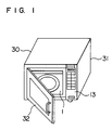
- Fig. 1 is a perspective view of the external appearance of a heating apparatus according to an embodiment of the present invention.
- Fig. 2 is a diagram showing a system block configuration of the essential parts of the same heating apparatus.
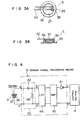
- Figs. 3A and 3B are diagrams for explaining a pyroelectric element of the heating apparatus in detail, of which Fig. 3A is a plan view and Fig. 3B is a sectional view.
- Fig. 4 shows a configuration of the essential parts arranged around sensor processing means and a pyroelectric element of the heating apparatus.
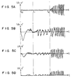
- Figs. 5A, 5B, 5C and 5D show waveforms observed at specific points (a-a′, b-b′, c-c′) in the circuit of Fig. 4.
- Figs. 6A and 6B are diagrams showing the detection signal of the pyroelectric element produced through sensor signal processing means of the heating apparatus and changes with time thereof.
- Fig. 7 is a flowchart showing a program structure for the heating control and the detection operation of an embodiment of the present invention.
- a microwave oven 30 comprises an operating section 13 for designating and applying an operation control command for the units on the front thereof, a body 31 on the outside thereof, and a freely openable door 32 in the opening of a heating chamber 1.
- the heating chamber 1 has mounted on the walls thereof a magnetron 3 for supplying microwave energy for heating an object 2 to be heated, an upper heater 35 and a lower heater 34 making up a second heat source for heating the object 2, and a lamp 14 for illuminating the interior of the heating chamber 1.
- a turntable 33 carrying the object 2 in the heating chamber 1 is driven by a turntable motor 18 and rotates to assure uniform heating of the object 2 while being heated.
- a fan motor 16 produces an airflow for cooling a high-voltage transformer 15 for supplying a high voltage to the magnetron 3 and the lamp 14 and also generates an airflow supplied into the heating chamber 1 for exhausting the water vapor and the like generated from the object 2 out of the heating chamber.
- the direction and amountof the airflow generated is regulated by an orifice 17 formed beside the fan motor 16.
- the high-voltage transformer 15, the fan motor 16 and the turntable motor 18 are controlled by drive means 11, the operation of which is in turn controlled by a control signal generated by the control section 4.
- a first exhaust path is formed of a route including a first exhaust port 1, a first exhaust guide 21 and a first vent 26 in that order
- a second exhaust path is formed of a route including a second exhaust port 20, a second exhaust guide 22, a vent pipe 23, exhaust guides A24 and B25 and a second vent 27 in that order.
- the heat-sensitive surface of a pyroelectric element having a pyroelectric characteristic is exposed from the interior wall surface of the second exhaust path.
- Figs. 3A and 3B are diagrams for explaining the pyroelectric element 5 in detail.
- the pyroelectric element 5 includes a flat ceramic plate 36 having a pyroelectric effect, electrodes 37 and 38 formed on the sides of the ceramic plate 36, and a metal plate 39 made of stainless steel or the like bonded to the surface of one of the electrodes 37 and 38.
- This metal plate 39 functions as a heat-sensitive surface of the pyroelectric element 5.
- a high-temperature gas like water vapor comes into contact with the metal plate 39, heat is transmitted to the ceramic plate 36 through the metal plate 39, and the ceramic plate 36 generates a voltage by the pyroelectric effect.
- the electrode 38 to which the metal plate 39 is bonded is partially extended to the opposite side of the ceramic plate 36 by way of a part of the periphery thereof, so that a lead wire 40 from the electrodes 37 and 38 may be taken out only by the side of the electrodes 37 and 38 to which the metal plate 39 is not bonded.
- the ceramic plate 36 may be composed of PZT (lead zirconate-titanate ceramics), for example.
- the pyroelectric element 5 is polarized in such a manner that the electrode 37 has a positive polarity and the electrode 38 a negative polarity. Under this condition of polarization, a positive (plus) voltage is generated across the electrode 37 with the increase in temperature of the pyroelectric element 5.
- the object to be heated (food) 2 placed in the heating chamber 1 is heated dielectrically by the microwave (high-frequency wave) of 2450 MHz generated from the magnetron 3.
- the object 2 gradually increases in temperature, and when it reaches a temperature near the boiling point of water, generates a large amount of high-temperature vapor.
- This vapor is passed through the second exhaust vent 20 formed in the ceiling of the heating chamber 1 and is applied against the pyroelectric element 5 through a cylindrical ventilation pipe 23.
- the vapor brought into contact with the pyroelectric element 5 supplies a great amount of thermal energy to the pyroelectric element 5.
- This thermal energy contains a great amount of latent heat generated by the vapor dewing on the surface of the pyroelectric element 5.
- the sharp temperature increase of the pyroelectric element 5 disturbs the equilibrium of polarization in the pyroelectric element 5, and generates a pulse signal with sharp voltage changes at the electrodes on the surface of the element.
- a similar pulse signal having opposite characteristics, also appears during a sharp temperature decrease such as when a heated pyroelectric element comes into contact with a cold air.
- the vapor generated from the object (food) 2 flows non-uniformly through the air lower in temperature than the vapor, and therefore the amount of the vapor coming into contact with the pyroelectric element 5 fluctuates with time and space. Even after the vapor comes to be generated steadily with the object 2 (food) increased beyond a certain temperture, temperature changes (fluctuations), that is, heat exchanges are repeated in which the pyroelectric element 5 increases in temperature due to a great amount of vapor at some moment while the temperature thereof decreases with the vapor amount decreased at a next moment, followed by a temperature increase due a great amount of vapor generated.
- the pyroelectric element 5 continues to generate an irregular pulse signal voltage (AC voltage) of positive and negative polarities in response to the heat exchange (temperature fluctuations) described above, while the object (food) 2 continues to generate a high-temperature vapor.
- AC voltage irregular pulse signal voltage
- the control section 4 decides the de-energization of the magnetron 3 and the cooling fan 16 as the basic principle of a detection system.
- Fig. 4 is a diagram showing a circuit configuration of the essential parts centered on the pyroelectric element 5 and the sensor signal processing means 12 of a heating apparatus, that is, a microwave oven according to an embodiment of the present invention, and Figs. 5A, 5B, 5C and 5D voltage waveforms observed at specific points (a-a', b-b', c-c') in the circuit configuration.
- Fig. 5A shows a waveform observed between the section a-a' when the microwave oven is energized a sufficient length of time after the previous use, that is, from a cold state
- Fig. 5B a waveform observed when the microwave oven is energized immediately after heating by the second heat source, that is, from a hot state.
- Fig. 5A showing the case of energization in a cold state
- the microwave oven is energized for heating at time t 0
- a signal is generated after a time t 2 when a great volume of vapor emanates from the food, namely the object 2 to be heated.
- Fig. 5B showing a case in which the second heat source including the upper heater 35 and the lower heater 34 has been used, a noise signal due to the residual vapor is generated and is mixed with the vapor signal requiring to be detected.
- the noise signal of Fig. 5B will be explained more in detail below.
- the fan motor 15 is energized and the cold air generated thereby cools the pyroelectric element 5.
- the temperature of the pyroelectric element 5 is reduced to generate a positive voltage (on the electrode 38) immediately after the start of the microwave oven.
- the airflow from the cooling fan 16 then causes the hot air remaining in the heating chamber 1 to reach the pyroelectric element 5 through the air path and increases the temperature of the pyroelectric element 5.
- the voltage across the element swings greatly to a negative value, thus generating a maximum voltage.
- the voltage thus swung to the negative value is shifted to a positive value with the temperature of the pyroelectric element 5 reaching the ceiling and decreasing again. Zero voltage is subsequently reached at equilibrium.
- This process of change occurs during a short period of several to several tens of seconds immediately after the energization of the microwave oven and is finished substantially within first 30 seconds (before time t 1 ). Even after termination of this transient voltage generated immediately after starting, however, the hot air remaining in the heating chamber 1 causes a noise voltage unlike under a cold state so that it coexists with the vapor signal requiring to be detected (Fig. 5B). The voltage waveform in the time period from t 1 to t 0 is caused by such a residual vapor.
- the signal is half-wave rectified by a rectification diode 41 before being read by the control sectin 4, and the polarity of the pyroelectric element 5 is selected in such a manner that the voltage (positive voltages in Figs. 5A - 5C) remains due to the negative temperature change of the pyroelectric element 5.
- the detecting operation is not affected by the negative voltage containing a maximum amplitude voltage generated by residual hot air and most liable to cause erroneous detection, among the voltages generated during a period of scores of seconds immediately following the start of the cooling fan 16.
- the voltages generated due to vapor or hot air by the pyroelectric element 5 are different in their manner of response, though both are caused by heat.
- a voltage of substantially the same positive or negative degree is generated either in the temperature rise time or in the temperature fall time, while, in response to hot air, a voltage comparatively lower is generated in the temperature fall time than in the temperature rise time. This is considered to be due to the fact that the temperature decrease is largely affected by the vaporization heat of waterdrops adhered when vapor is involved, while the voltage generation due to hot air is not accompanied by any similar physical change.
- the sensitivity characteristic of the pyroelectric element 5 is such that, in the process of vapor detection after the heater energization, the noise voltage generated by hot air has a small voltage amplitude as compared with that of the detection voltage due to vapor during a temperature decrease.
- the present circuit configuration and the polarity of connection of the pyroelectric element 5 reduces remarkably the possibility of detecting a noise voltage erroneously as a vapor signal.
- the frequency components of the detection signal generated by the resistor 46 spread over a comparatively wide area up to the frequency range higher than 6 Hz, while the noise voltage due to hot air is mainly caused by the fluctuations of hot air induced by the revolution of the turntable 33 of one rotation for each ten seconds.
- the change in the noise voltage therefore, is comparatively slow with the frequency components thereof distributed mainly in the range from 1/T 1 Hz (T 1 : Rotational period of the turntable 33) to two Hz.
- the low-frequency control means including the high-pass RC circuit 43 attenuates the noise components due to the residual vapor mainly comprised-of low frequencies to a degree more than the signal components due to vapor. Determination of the frequency range to be suppressed depends on the relationship between the frequency components of the signal voltage to be detected and that of the noise voltage to attenuated. The above-mentioned conditions, however, make it a best solution to set the upper limit of the frequency to be dampened substantially in a range from two to 1/T 1 Hz, or more specifically, in a range from one to two Hz.
- the high-pass RC circuit 43 functions also as a DC-cutting circuit for preventing the DC voltage from being applied to the pyroelectric element 5.
- the pyroelectric element 5 generally includes a silver electrode, and the application thereto of a DC voltage is required to be prevented to avoid the deterioration of insulation caused by migration of silver.
- Fig. 5C shows a voltage waveform passed through the high-pass RC circuit in this way, and Fig. 5D the same voltage waveform further half-wave rectified by the rectification diode 41 and applied to the control section 4. The noise voltage generated by residual vapor in the heating chamber 1 is thus greatly dampened by the sensor signal processing means 12 before being applied to the control section 4.
- the control section has the function of not only applying an indication output signal to the operating section 13 in response to an input signal from the input keyboard of the operating means 13 and producing a signal for driving the drive means 11 to heat the object 2 by energization of the magnetron 3 or rotating the turntable 3, but also making decisions for controlling various parts on the basis of a signal voltage transmitted from the pyroelectric element 5 through the sensor signal processing means 12.
- a control signal from the control section 4 is applied to the drive means 11 which then causes the operations of the magnetron 3 (high-voltage transformer 15), the fan motor 16 and the turntable 18 to be started (step a).
- the counting of the heating time T is started in the control section 4 (step b).
- the next step is to wait until the heating time T reaches a starting time T 1 of a predetermined length of time (step c).
- the voltage value D of the signal voltage is read by measuring means 6 (step d).
- the voltage value D read is recorded by the recording means 7 and the recording means 7 determines the largest voltage value D as a maximum value D m , and the voltage value D read subsequently is assumed as a new maximum value D m if larger than the recorded maximum value D m (step e).
- the steps d and e are repeated until the time T 2 where the predetermined time elapses.
- a threshold value corresponding to the maximum value D m recorded in the recording means 7 is determined by threshold value-setting means 8 (step g).
- the maximum value D m among the voltage values D measured repeatedly during a predetermined period of time (from T 1 to T 2 ) after heating start by the measuring means 6 in the control section 4 is recorded by the recording means 7.
- the threshold value selection means 8 of the control section 4 determines a threshold value providing a detection level for the value D m recorded by the recording means 7.
- the count N of the counter reaches a predetermined number, say, five
- the detection time td is recorded as a time when the object 2 has been heated optimally.
- the number of times the pulse signal exceeds the threshold value is counted in such a manner that when the threshold level is exceeded for a predetermined length of time or more, for example, 100 ms or more, one count is added.
- Table 1 shown below is an example of a classification table used for selecting a threshold value.
- Table 1 D m Threshold value 0v ⁇ D m ⁇ 0.3v 0.5v 0.3v ⁇ D m ⁇ 2.5v D m + 0.4v 2.5v ⁇ D m 3.0v
- Table 1 three constants including 0.5, 0.4 and 3.0 are prepared for setting a threshold level respectively for the three ranges of D m , and a threshold value is determined according to this table.
- Fig. 6A shows an example of starting the heating operation from the cold state of the microwave oven (after being left to stand for at least a predetermined length of time from the preceding operation).
- Fig. 6B shows an example of starting a heating operation immediately after the heater operation when a great amount of residual hot air remains in the heating chamber 1.
- the signal level remains substantially zero during the period from the heating start to generation of vapor from the object 2, and the maximum value D m detected during a first predetermined period of time (T 1 to T 2 ) is 0.2v.
- the threshold value is thus set to 0.5v.
- the comparison-decision means 9 comes to determine a finish detection time as t d .
- the great amount of residual hot air in the heating chamber 1 causes a signal level of a considerable amplitude to be observed from the time immediately after starting the heating operation, and the maximum value D m is 0.7v.
- the threshold value is thus set to a level of 1.1v which is higher than the signal level (D m ) generated by the residual hot air, which level is of course higher than the level set for the cold start in Fig. 6A.
- the threshold level for determining the finish detection time t d is set in accordance with a signal voltage due to the residual hot air or the like detected before generation of vapor from the object 2. Erroneous detection (premature de-energization) is therefore prevented which otherwise might be caused by a signal voltage due to the residual hot air such as when the apparatus is started in a hot condition immediately after the heating with the heater.
- the threshold level is fixed at 3.0v regardless of the value D m for the purpose of preventing an excessive threshold level from leading to a detection failure (preventing the signal due to the vapor generated from the object from reaching a threshold level).
- the pyroelectric element 5 composed of a ceramic element having a pyroelectricity according to the present embodiment may have piezoelectricity at the same time.
- a piezoelectric buzzer or an ultrasonic microphone using the characteristics of a piezoelectric element, for example, is of course applicable to the present invention with equal effect to the extent that they have pyroelectricity.
- the comparison-decision means counts signal pulses exceeding the threshold level for a predetermined length of time.
Landscapes
- Physics & Mathematics (AREA)
- Electromagnetism (AREA)
- Engineering & Computer Science (AREA)
- Chemical & Material Sciences (AREA)
- Combustion & Propulsion (AREA)
- Mechanical Engineering (AREA)
- General Engineering & Computer Science (AREA)
- Electric Ovens (AREA)
- Control Of High-Frequency Heating Circuits (AREA)
Description
- The present invention relates to a heating apparatus comprising a detection system for detecting high temperature water vapor emanating from an object and controlling a heat source by using the detection signal.
- A heating apparatus having a system for detecting automatically a finished state of a heated object finds applications in various forms. A humidity sensor for detecting humidity changes is most widely used as a detector for the detection system of such an automatic heating apparatus. The humidity sensor is used to detect changes in electrical resistance of an element due to the water molecules adsorbed on the surface thereof. In order to prevent the deterioration in sensitivity due to the smear of the element surface and to maintain a stable performance over a long period, it is necessary to burn off the smear from the element surface or take any other complicated procedure at regular intervals of time.
- As disclosed in EP-A-0367186 on the other hand, the inventors are studying a system in which the water vapor or other vaporized substance of a high humidity emanating from an object being heated, is collected by way of a vent formed in the wall of a heating chamber and is applied against a pyroelectric element outside of the heating chamber to detect a finished state of heating through a voltage generated from the pyroelectric element. This system is based on a physical phenomenon of a detection mechanism exchanging heat between the pyroelectric element and the vapor, and therefore unlike in conventional humidity sensors, the sensitivity would not be substantially affected by the smear of the element surface, thereby leading to the advantage of constructing a detection system in a very simple manner in principle.
- EP-A-0198430 discloses a heating apparatus which utilizes a piezoelectric sensor in a similar way.
- However, because both these systems utilize temperature changes of a pyroelectric element caused by the heat of the vapor they both suffer the disadvantage that the pyroelectric element can be undesirably energized to generate a voltage not only by vapor generated from an object but also by high-temperature air, that is, hot air applied suddenly thereto. In the case of a microwave oven comprising an electric or gas heater as a secondary heat source other than the microwave, hot air from the heat source remains in substantial amounts immediately after a heating operation. If an object is heated with the microwave under this condition, the pyroelectric element responsive to the residual hot air can generate a voltage regardless of the temperature of the food, with the result that there is a failure to discriminate a voltage due to the vapor emanating from the heating of the food, which can lead to an erroneous detection.
- This problem is liable to be caused also after a long heating operation with a microwave alone, as well as after heating with an auxiliary heater of a microwave oven, because of a similar phenomenon to the one mentioned above due to an increased temperature of the heating chamber or the like, thus making it difficult to detect a heated condition of the object food (a finished condition by heat) with high accuracy without error.
- With the increase in the temperature of the pyroelectric element, the smaller temperature difference with the vapor generated from the food reduces the detection sensitivity. The detection sensitivity undergoing changes in various fashions in this way according to the operating conditions has presented the problem of the difficulty of securing stable detection accuracy.
- An example of a prior art arrangement which makes use of a pyroelectric element is described in EP-A-0353691.
- It is to be noted that both EP-A-0367186 and EP-A-0353691, despite having an earlier priority date than the present invention, were published after the priority date of the present invention. Therefore, these documents are not to be considered in deciding whether the present invention involves an inventive step.
- In view of the foregoing background, an object of the present invention is to provide a heating system using a pyroelectric element which is capable of detecting a high vapor temperature accurately without erroneously detecting residual heat in the heating chamber in repeated continuous operations of the heating apparatus when the apparatus body is heated to some degree such as immediately after the completion of a heater operation and besides regardless of a change in the sensitivity.
- According to a first aspect of the present invention there is provided a heating apparatus comprising:
- a heating chamber (1) for accommodating an object (2) to be heated;
- a heating means (3) for heating the object;
- an air path (20) for leading air in the heating chamber (1) to the exterior of said chamber (1);
- a pyroelectric element (5) disposed in the air path (20) for sensing temperature fluctuations in said air;
- wherein said pyroelectric element (5) generates, in use, a sensor signal including a noise signal caused by residual heat in said air and a vapor signal caused by hot water vapor produced from the object (2); and
- a control section comprising:
- a comparison-decision means (9) for deciding whether said voltage has reached a predetermined detection level and outputting a result of the decision; and
- a drive means (11) for controlling the heating means (3) on the basis of said result;
- said apparatus being characterized in that s a i d control section further comprises:
- a measuring means for measuring said voltage;
- a recording means for recording a peak value of said voltage during a predetermined length of time after the commencement of heating;
- a threshold setting means for setting a threshold value corresponding to said peak value;
- wherein said threshold voltage is set in accordance with the signal voltage caused by the residual heat of said air when said heating is commenced with said air in a hot state;
- whereby even if said heating is commenced with said air in a hot state, said threshold is not exceeded before hot water vapor is produced from said object and hence premature de-energization is prevented.
- According to a second aspect of the present invention there is provided a method of controlling a heating apparatus according to the first aspect of the present invention characterised by the steps of:
- detecting a peak value of said sensor signal during a predetermined length of time and storing a first value representing said peak value,
- obtaining a second value representing a threshold level from a table which has been set beforehand in accordance with the first value and storing the second value, and
- deciding the value of at least a selected one of:
- a frequency at which the sensor signal continuously exceeds the second value for a length of time longer than a predetermined length of time; and
- an accumulated time during which the sensor signal continuously exceeds the second value; and
- controlling the operation of said heating means by detecting that the value thus decided has reached a predetermined value.
- One embodiment of the invention includes a section associated with sensor signal processing means for processing a voltage generated by the pyroelectric element and a control section for controlling various operations of the apparatus in response to a signal voltage processed by the sensor signal processing means.
- First, the part of the embodiment relating to the sensor signal processing means will be explained. A first feature of this part is that the sensor signal processing means is configured to selectively eliminate a voltage of the polarity generated by the discharge of heat from a pyroelectric element (such as when temperature drops) among the voltages generated with the heat exchange of the pyroelectric element. The sensitivity to heat is thus reduced below that of the sensitivity to vapor. A second feature lies in that, of all the voltages generated from the pyroelectric element, the comparatively low frequency components generated by the pyroelectric element as a result of heat exchange with the residual hot air in the heating chamber are eliminated to remove the factors of erroneous detection. This residual hot air is induced with the drive of a turntable or like means for assuring uniform microwave heating which operates slower than the heat exchange caused by fluctuations of vapor from the object to be heated.
- By use of the aforementioned two means, the voltage generated by the heat of the residual hot air or the like other than the vapor generated from the object of heating is greatly dampened and eliminated as compared with the signal voltage generated by the vapor from the object, thereby preventing erroneous detection.
- Now, an explanation will be made of the control section for receiving a signal voltage from the sensor signal processing means to effect detection and control. The voltage output of the pyroelectric element immediately after starting the heating operation is measured for a first predetermined length of time, and a threshold value providing a detection level is set from a formula based on the measured signal level as a noise level. The control section thus has a function to decide a finished condition by detecting a voltage output higher than the threshold produced by the pyroelectric element in response to the vapor emanating from the object food.
- As a result, erroneous detection, (premature de-energization) due to residual heat or detection result dispersion due to sensor sensitivity dispersion can be minimized.
- The invention will be described now by way of example only, with particular reference to the accompanying drawings. In the drawings:
- Fig. 1 is a perspective view of the external appearance of a heating apparatus according to an embodiment of the present invention.
- Fig. 2 is a diagram showing a system block configuration of the essential parts of the same heating apparatus.
- Figs. 3A and 3B are diagrams for explaining a pyroelectric element of the heating apparatus in detail, of which Fig. 3A is a plan view and Fig. 3B is a sectional view.
- Fig. 4 shows a configuration of the essential parts arranged around sensor processing means and a pyroelectric element of the heating apparatus.
- Figs. 5A, 5B, 5C and 5D show waveforms observed at specific points (a-a′, b-b′, c-c′) in the circuit of Fig. 4.
- Figs. 6A and 6B are diagrams showing the detection signal of the pyroelectric element produced through sensor signal processing means of the heating apparatus and changes with time thereof.
- Fig. 7 is a flowchart showing a program structure for the heating control and the detection operation of an embodiment of the present invention.
- A microwave oven with a heater providing a heating apparatus according to an embodiment of the present invention will be explained below with reference to the accompanying drawings.
- As shown in Fig. 1, a
microwave oven 30 comprises anoperating section 13 for designating and applying an operation control command for the units on the front thereof, abody 31 on the outside thereof, and a freelyopenable door 32 in the opening of aheating chamber 1. - It is seen from Fig. 2, on the other hand, that the
heating chamber 1 has mounted on the walls thereof amagnetron 3 for supplying microwave energy for heating anobject 2 to be heated, anupper heater 35 and alower heater 34 making up a second heat source for heating theobject 2, and alamp 14 for illuminating the interior of theheating chamber 1. Aturntable 33 carrying theobject 2 in theheating chamber 1 is driven by aturntable motor 18 and rotates to assure uniform heating of theobject 2 while being heated. Afan motor 16 produces an airflow for cooling a high-voltage transformer 15 for supplying a high voltage to themagnetron 3 and thelamp 14 and also generates an airflow supplied into theheating chamber 1 for exhausting the water vapor and the like generated from theobject 2 out of the heating chamber. The direction and amountof the airflow generated is regulated by anorifice 17 formed beside thefan motor 16. - The high-
voltage transformer 15, thefan motor 16 and theturntable motor 18 are controlled by drive means 11, the operation of which is in turn controlled by a control signal generated by thecontrol section 4. - The air sent from the
fan motor 16, after entering theheating chamber 1, is exhausted out of the apparatus containing a water vapor gas of theobject 2 by way of two exhaust paths. A first exhaust path is formed of a route including afirst exhaust port 1, a first exhaust guide 21 and afirst vent 26 in that order, and a second exhaust path is formed of a route including asecond exhaust port 20, asecond exhaust guide 22, avent pipe 23, exhaust guides A24 and B25 and a second vent 27 in that order. The heat-sensitive surface of a pyroelectric element having a pyroelectric characteristic is exposed from the interior wall surface of the second exhaust path. - Figs. 3A and 3B are diagrams for explaining the
pyroelectric element 5 in detail. Thepyroelectric element 5 includes a flatceramic plate 36 having a pyroelectric effect,electrodes ceramic plate 36, and ametal plate 39 made of stainless steel or the like bonded to the surface of one of theelectrodes metal plate 39 functions as a heat-sensitive surface of thepyroelectric element 5. When a high-temperature gas like water vapor comes into contact with themetal plate 39, heat is transmitted to theceramic plate 36 through themetal plate 39, and theceramic plate 36 generates a voltage by the pyroelectric effect. In the case of thepyroelectric element 5 shown in Fig. 3, theelectrode 38 to which themetal plate 39 is bonded is partially extended to the opposite side of theceramic plate 36 by way of a part of the periphery thereof, so that alead wire 40 from theelectrodes electrodes metal plate 39 is not bonded. - The
ceramic plate 36 may be composed of PZT (lead zirconate-titanate ceramics), for example. Thepyroelectric element 5 is polarized in such a manner that theelectrode 37 has a positive polarity and the electrode 38 a negative polarity. Under this condition of polarization, a positive (plus) voltage is generated across theelectrode 37 with the increase in temperature of thepyroelectric element 5. - As shown in Fig. 2, the object to be heated (food) 2 placed in the
heating chamber 1 is heated dielectrically by the microwave (high-frequency wave) of 2450 MHz generated from themagnetron 3. Theobject 2 gradually increases in temperature, and when it reaches a temperature near the boiling point of water, generates a large amount of high-temperature vapor. This vapor is passed through thesecond exhaust vent 20 formed in the ceiling of theheating chamber 1 and is applied against thepyroelectric element 5 through acylindrical ventilation pipe 23. The vapor brought into contact with thepyroelectric element 5 supplies a great amount of thermal energy to thepyroelectric element 5. This thermal energy of course contains a great amount of latent heat generated by the vapor dewing on the surface of thepyroelectric element 5. - The sharp temperature increase of the
pyroelectric element 5 disturbs the equilibrium of polarization in thepyroelectric element 5, and generates a pulse signal with sharp voltage changes at the electrodes on the surface of the element. A similar pulse signal, having opposite characteristics, also appears during a sharp temperature decrease such as when a heated pyroelectric element comes into contact with a cold air. - The vapor generated from the object (food) 2 flows non-uniformly through the air lower in temperature than the vapor, and therefore the amount of the vapor coming into contact with the
pyroelectric element 5 fluctuates with time and space. Even after the vapor comes to be generated steadily with the object 2 (food) increased beyond a certain temperture, temperature changes (fluctuations), that is, heat exchanges are repeated in which thepyroelectric element 5 increases in temperature due to a great amount of vapor at some moment while the temperature thereof decreases with the vapor amount decreased at a next moment, followed by a temperature increase due a great amount of vapor generated. - As a result, the
pyroelectric element 5 continues to generate an irregular pulse signal voltage (AC voltage) of positive and negative polarities in response to the heat exchange (temperature fluctuations) described above, while the object (food) 2 continues to generate a high-temperature vapor. - In this way, as the temperature of the
object 2 approaches the boiling point of water with the heating operation of the microwave oven, vapor is abruptly generated from theobject 2, thereby causing generation of a pulse voltage (AC voltage) v (several mv) of positive and negative polarities in large amplitude corresponding to the fluctuations between the electrodes of thepyroelectric element 5. The voltage thus generated by thepyroelectric element 5 is transmitted through the sensor signal processing means 12 to thecontrol section 4. - If the
object 2 is in a reheating (food-reheating) menu, for instance, a substantially sufficient temperature is reached for the purpose of heating when a great amount of vapor begins to emanate. When the voltage generated from thepyroelectric element 5 reaches a predetermined detection level (threshold value), therefore, thecontrol section 4 decides the de-energization of themagnetron 3 and the coolingfan 16 as the basic principle of a detection system. - Fig. 4 is a diagram showing a circuit configuration of the essential parts centered on the
pyroelectric element 5 and the sensor signal processing means 12 of a heating apparatus, that is, a microwave oven according to an embodiment of the present invention, and Figs. 5A, 5B, 5C and 5D voltage waveforms observed at specific points (a-a', b-b', c-c') in the circuit configuration. - Fig. 5A shows a waveform observed between the section a-a' when the microwave oven is energized a sufficient length of time after the previous use, that is, from a cold state, and Fig. 5B a waveform observed when the microwave oven is energized immediately after heating by the second heat source, that is, from a hot state.
- In Fig. 5A showing the case of energization in a cold state, the microwave oven is energized for heating at time t0, and a signal is generated after a time t2 when a great volume of vapor emanates from the food, namely the
object 2 to be heated. In Fig. 5B showing a case in which the second heat source including theupper heater 35 and thelower heater 34 has been used, a noise signal due to the residual vapor is generated and is mixed with the vapor signal requiring to be detected. The noise signal of Fig. 5B will be explained more in detail below. - Simultaneously with the start of the heating operation of the microwave oven at time t0, the
fan motor 15 is energized and the cold air generated thereby cools thepyroelectric element 5. As a result, the temperature of thepyroelectric element 5 is reduced to generate a positive voltage (on the electrode 38) immediately after the start of the microwave oven. The airflow from the coolingfan 16 then causes the hot air remaining in theheating chamber 1 to reach thepyroelectric element 5 through the air path and increases the temperature of thepyroelectric element 5. The voltage across the element swings greatly to a negative value, thus generating a maximum voltage. The voltage thus swung to the negative value is shifted to a positive value with the temperature of thepyroelectric element 5 reaching the ceiling and decreasing again. Zero voltage is subsequently reached at equilibrium. - This process of change occurs during a short period of several to several tens of seconds immediately after the energization of the microwave oven and is finished substantially within first 30 seconds (before time t1). Even after termination of this transient voltage generated immediately after starting, however, the hot air remaining in the
heating chamber 1 causes a noise voltage unlike under a cold state so that it coexists with the vapor signal requiring to be detected (Fig. 5B). The voltage waveform in the time period from t1 to t0is caused by such a residual vapor. - In a circuit configuration including the sensor signal processing means 12 and the
pyroelectric element 5 shown in Fig. 4 the signal is half-wave rectified by arectification diode 41 before being read by thecontrol sectin 4, and the polarity of thepyroelectric element 5 is selected in such a manner that the voltage (positive voltages in Figs. 5A - 5C) remains due to the negative temperature change of thepyroelectric element 5. As seen from Fig. 5B, therefore, the detecting operation is not affected by the negative voltage containing a maximum amplitude voltage generated by residual hot air and most liable to cause erroneous detection, among the voltages generated during a period of scores of seconds immediately following the start of the coolingfan 16. - Further, the voltages generated due to vapor or hot air by the
pyroelectric element 5 are different in their manner of response, though both are caused by heat. In response to vapor, a voltage of substantially the same positive or negative degree is generated either in the temperature rise time or in the temperature fall time, while, in response to hot air, a voltage comparatively lower is generated in the temperature fall time than in the temperature rise time. This is considered to be due to the fact that the temperature decrease is largely affected by the vaporization heat of waterdrops adhered when vapor is involved, while the voltage generation due to hot air is not accompanied by any similar physical change. The sensitivity characteristic of thepyroelectric element 5 is such that, in the process of vapor detection after the heater energization, the noise voltage generated by hot air has a small voltage amplitude as compared with that of the detection voltage due to vapor during a temperature decrease. The present circuit configuration and the polarity of connection of thepyroelectric element 5 reduces remarkably the possibility of detecting a noise voltage erroneously as a vapor signal. - The sensor signal processing means shown in Fig. 4 further includes a high-
pass RC circuit 43 having acapacitor 42 and aresistor 46 with a time constant thereof determined approximately as T = 0.5 or 1.0. The frequency components of the detection signal generated by theresistor 46 spread over a comparatively wide area up to the frequency range higher than 6 Hz, while the noise voltage due to hot air is mainly caused by the fluctuations of hot air induced by the revolution of theturntable 33 of one rotation for each ten seconds. The change in the noise voltage, therefore, is comparatively slow with the frequency components thereof distributed mainly in the range from 1/T1 Hz (T1 : Rotational period of the turntable 33) to two Hz. Even in the case where the noise is mixed under a hot state as mentioned above, the low-frequency control means including the high-pass RC circuit 43 attenuates the noise components due to the residual vapor mainly comprised-of low frequencies to a degree more than the signal components due to vapor. Determination of the frequency range to be suppressed depends on the relationship between the frequency components of the signal voltage to be detected and that of the noise voltage to attenuated. The above-mentioned conditions, however, make it a best solution to set the upper limit of the frequency to be dampened substantially in a range from two to 1/T1 Hz, or more specifically, in a range from one to two Hz. The result is an improved signal-to-noise ratio of the vapor signal and a greatly reduced probability of erroneous detection. The high-pass RC circuit 43 of course functions also as a DC-cutting circuit for preventing the DC voltage from being applied to thepyroelectric element 5. Thepyroelectric element 5 generally includes a silver electrode, and the application thereto of a DC voltage is required to be prevented to avoid the deterioration of insulation caused by migration of silver. Fig. 5C shows a voltage waveform passed through the high-pass RC circuit in this way, and Fig. 5D the same voltage waveform further half-wave rectified by therectification diode 41 and applied to thecontrol section 4. The noise voltage generated by residual vapor in theheating chamber 1 is thus greatly dampened by the sensor signal processing means 12 before being applied to thecontrol section 4. - The control section has the function of not only applying an indication output signal to the
operating section 13 in response to an input signal from the input keyboard of the operating means 13 and producing a signal for driving the drive means 11 to heat theobject 2 by energization of themagnetron 3 or rotating theturntable 3, but also making decisions for controlling various parts on the basis of a signal voltage transmitted from thepyroelectric element 5 through the sensor signal processing means 12. - Now, a method of detection and control by the
control section 4 will be explained with reference to Figs. 6A, 6B and 7. - First, the sequence and method of heating and automatic detection according to the present embodiment will be explained with reference to the flowchart of Fig. 7. Upon depression of a heating start key with an
object 2 placed in theheating chamber 1, a control signal from thecontrol section 4 is applied to the drive means 11 which then causes the operations of the magnetron 3 (high-voltage transformer 15), thefan motor 16 and theturntable 18 to be started (step a). The counting of the heating time T is started in the control section 4 (step b). The next step is to wait until the heating time T reaches a starting time T1 of a predetermined length of time (step c). The voltage value D of the signal voltage is read by measuring means 6 (step d). The voltage value D read is recorded by the recording means 7 and the recording means 7 determines the largest voltage value D as a maximum value Dm, and the voltage value D read subsequently is assumed as a new maximum value Dm if larger than the recorded maximum value Dm (step e). The steps d and e are repeated until the time T2 where the predetermined time elapses. A threshold value corresponding to the maximum value Dm recorded in the recording means 7 is determined by threshold value-setting means 8 (step g). After time T2, comparison-decision means 9 adds "1" to the count N (N = N + 1), if the signal voltage exceeds the threshold value for a predetermined length of time (step h). This step h is repeated until the count N reaches a predetermined value (say, 5) (step i). When N reaches 5, T = td is recorded as a detection time, and various parts including the magnetron are controlled accordingly (step j). - A method of decision and control has been explained above with reference to a flowchart. Now, the relationship between an output signal and a decision will be explained mainly with reference to Figs. 6A and 6B.
- The maximum value Dm among the voltage values D measured repeatedly during a predetermined period of time (from T1 to T2) after heating start by the measuring means 6 in the
control section 4 is recorded by the recording means 7. The threshold value selection means 8 of thecontrol section 4 determines a threshold value providing a detection level for the value Dm recorded by the recording means 7. - After time T2, the comparison-decision means 9 determines whether the detection signal has reached the threshold level, and if the threshold level is exceeded a predetermined number of times in succession, the count N of the counter in the comparison-decision means 9 is incremented by one (N = N + 1). When the count N of the counter reaches a predetermined number, say, five, the detection time td is recorded as a time when the
object 2 has been heated optimally. In the process, the number of times the pulse signal exceeds the threshold value is counted in such a manner that when the threshold level is exceeded for a predetermined length of time or more, for example, 100 ms or more, one count is added. - Table 1 shown below is an example of a classification table used for selecting a threshold value.
Table 1 Dm Threshold value 0v ≦ Dm < 0.3v 0.5v 0.3v ≦ Dm < 2.5v Dm + 0.4v 2.5v ≦ Dm 3.0v - In Table 1, three constants including 0.5, 0.4 and 3.0 are prepared for setting a threshold level respectively for the three ranges of Dm, and a threshold value is determined according to this table.
- The relationship between the signal level and detection time td based on Table 1 will be explained with reference to Figs. 6A and 6B. Fig. 6A shows an example of starting the heating operation from the cold state of the microwave oven (after being left to stand for at least a predetermined length of time from the preceding operation). Fig. 6B shows an example of starting a heating operation immediately after the heater operation when a great amount of residual hot air remains in the
heating chamber 1. In the case of Fig. 6A, the signal level remains substantially zero during the period from the heating start to generation of vapor from theobject 2, and the maximum value Dm detected during a first predetermined period of time (T1 to T2) is 0.2v. The threshold value is thus set to 0.5v. As a result, the comparison-decision means 9 comes to determine a finish detection time as td. In the case of Fig. 6B, on the other hand, the great amount of residual hot air in theheating chamber 1 causes a signal level of a considerable amplitude to be observed from the time immediately after starting the heating operation, and the maximum value Dm is 0.7v. The threshold value is thus set to a level of 1.1v which is higher than the signal level (Dm) generated by the residual hot air, which level is of course higher than the level set for the cold start in Fig. 6A. - As explained above, the threshold level for determining the finish detection time td is set in accordance with a signal voltage due to the residual hot air or the like detected before generation of vapor from the
object 2. Erroneous detection (premature de-energization) is therefore prevented which otherwise might be caused by a signal voltage due to the residual hot air such as when the apparatus is started in a hot condition immediately after the heating with the heater. - In addition, in the case where the maximum value Dm is larger than a predetermined value, or when 2.5 < Dm as shown in Table 1, the threshold level is fixed at 3.0v regardless of the value Dm for the purpose of preventing an excessive threshold level from leading to a detection failure (preventing the signal due to the vapor generated from the object from reaching a threshold level).
- The
pyroelectric element 5 composed of a ceramic element having a pyroelectricity according to the present embodiment may have piezoelectricity at the same time. A piezoelectric buzzer or an ultrasonic microphone using the characteristics of a piezoelectric element, for example, is of course applicable to the present invention with equal effect to the extent that they have pyroelectricity. - The advantages of the present heating apparatus are as follows.
- (1) The sensor signal processing means is so configured as to selectively eliminate a voltage of the polarity (half wave) generated during the temperature decrease of a pyroelectric element among the voltages generated by the pyroelectric element. Further, even when the apparatus is started with a great amount of hot air remaining in the heating chamber after the operation of the heater, the voltage of a large amplitude generated with a temperature rise of the pyroelectric element due to the residual hot air for several tens of seconds immediately after the start of operation can be removed thereby to prevent erroneous detection which otherwise might be caused by this type of residual hot air. Further, the pyroelectric element has such a sensitivity characteristic that the sensitivity thereof to the hot air fluctuations during temperature decrease is lower than that to the vapor fluctuations. Erroneous detection due to the residual hot air occurs less.
- (2) The sensor signal processing means comprise low-frequency wave dampening means for removing a slowly changing frequency component, and therefore it is adapted to remove the voltage component caused by heat exchange with the residual hot air induced by the operation of the turntable or the like having a lower change rate than the fluctuation signal of the vapor generated from the object. The probability of occurrence of erroneous detection due to the residual hot air is thus remarkably reduced.
- (3) In making a decision on the detection at the control section, a maximum value of the signal voltage is detected for a predetermined length of time (first predetermined time) after the heating operation has started. The number of times is counted by which a voltage pulse longer than a predetermined time width exceeds a threshold level set as a detection level for the maximum value according to a predetermined rule. The time when the count reaches a predetermined number (say, five) is regarded as a detection time point td. This method permits detection of an effective voltage signal level and obviates the problem of premature de-energization by erroneously detecting a noise signal of a high level due to the vapor remaining in the heating chamber immediately after the heater operation.
- In particular, while the first discrimination means detects a substantial maximum value and determines a corresponding threshold level, the comparison-decision means counts signal pulses exceeding the threshold level for a predetermined length of time. By changing the method of deciding a signal voltage in this way, a noise signal and a vapor signal can be discriminated from each other with higher accuracy.
Claims (8)
- A heating apparatus comprising:a heating chamber (1) for accommodating an object (2) to be heated;a heating means (3) for heating the object;an air path (20) for leading air in the heating chamber (1) to the exterior of said chamber (1);a pyroelectric element (5) disposed in the air path (20) for sensing temperature fluctuations in said gas;wherein said pyroelectric element (5) generates, in use, a sensor signal including a noise signal caused by residual heat in said air and a vapor signal caused by hot water vapor produced from the object (2); anda control section comprising:a comparison-decision means (9) for deciding whether said voltage has reached a predetermined detection level and outputting a result of the decision; anda drive means (11) for controlling the heating means (3) on the basis of said result;said apparatus being characterized in that s a i d control section further comprises:a measuring means (6) for measuring said voltage;a recording means (7) for recording a peak value of said voltage during a predetermined length of time after the commencement of heating;a threshold setting means (8) for setting a threshold value corresponding to said peak value;wherein said threshold voltage is set in accordance with the signal voltage caused by the residual heat of said gas when said heating is commenced with said air in a hot state;whereby even if said heating is commenced with said air in a hot state, said threshold is not exceeded before hot water vapor is produced from said object and hence premature de-energization is prevented.
- A heating apparatus according to claim 1, further comprising:a sensor signal processing means (12) for suppressing said noise signal from said sensor signal;wherein at least one of said sensor signal processing means (12) and said control section (4) includes selection means (41) for selectively accepting a voltage of a preselected polarity of the sensor signal generated by said pyroelectric element (5), said voltage of the preselected polarity being generated when the temperature of said pyroelectric element (5) falls, thereby suppressing the noise signal having a peak value of the reverse polarity produced by a temperature rise of said pyroelectric element (5) owing to heat exchange between said residual hot air and said pyroelectric element (5) after a heating operation is started and before a substantial amount of hot water vapor is produced from the object (2).
- A heating apparatus according to claim 2, wherein said sensor signal processing means (12) includes a diode (41).
- A heating apparatus according to claim 1, further comprisinga rotary means (33) for assuring uniform microwave heating and for mounting the object (2) thereon, said rotary means (33) rotating at a rotational period of T1 which is longer than 0.5 seconds;wherein said sensor signal processing means (12) includes low-frequency suppressing means (43) for suppressing said noise signal, said low-frequency eliminating means (43) having an upper limit frequency in a range from 1/T1 Hz to 2 Hz, thereby suppressing said noise signal having a low frequency in a range from 1/T1 Hz to 2 Hz caused by fluctuations of said residual hot air caused by the rotation of said rotary means, said noise signal caused by the fluctuations of said residual hot air being generated subsequent to the generation of said noise signal having a peak value of a negative polarity produced by a temperature rise of said pyroelectric element (5) caused by heat exchange between said residual hot air and said pyroelectric element (5) after a heating operation is started and before a substantial amount of hot water vapor is produced from the object (2).
- A heating apparatus according to claim 4, wherein said low-frequency suppressing means is a high-pass RC circuit (43).
- A heating apparatus according to claim 1, wherein said threshold setting means (8) decides said threshold value by using a predetermined table on the basis of said peak value (Dm) and stores the threshold value thus calculated.
- A method of controlling a heating apparatus as set out in claim 1, said method being characterized by the steps of:detecting a peak value (Dm) of said sensor signal during a predetermined length of time and storing a first value representing said peak value (Dm),obtaining a second value representing a threshold level from a table which has been set beforehand in accordance with the first value and storing the second value, anda third step of deciding the value of at least a selected one of:a frequency at which the sensor signal continuously exceeds the second value for a length of time longer than a predetermined length of time; andan accumulated time during which the sensor signal continuously exceeds the second value; andcontrolling the operation of said heating means (3) by detecting that the value thus decided has reached a predetermined value.
- A method of controlling a heating apparatus according to claim 7, wherein the table which has been set beforehand for use in the second step is such that the second value is set to a predetermined fixed value regardless of the magnitude of the first value when the first value is larger than a predetermined value.
Applications Claiming Priority (4)
| Application Number | Priority Date | Filing Date | Title |
|---|---|---|---|
| JP9940789 | 1989-04-19 | ||
| JP99407/89 | 1989-04-19 | ||
| JP115330/89 | 1989-05-09 | ||
| JP11533089 | 1989-05-09 |
Publications (3)
| Publication Number | Publication Date |
|---|---|
| EP0394010A2 EP0394010A2 (en) | 1990-10-24 |
| EP0394010A3 EP0394010A3 (en) | 1992-04-22 |
| EP0394010B1 true EP0394010B1 (en) | 1996-09-11 |
Family
ID=26440547
Family Applications (1)
| Application Number | Title | Priority Date | Filing Date |
|---|---|---|---|
| EP90304139A Expired - Lifetime EP0394010B1 (en) | 1989-04-19 | 1990-04-18 | Heating apparatus |
Country Status (6)
| Country | Link |
|---|---|
| US (1) | US5235148A (en) |
| EP (1) | EP0394010B1 (en) |
| KR (1) | KR930008249B1 (en) |
| AU (1) | AU613830B2 (en) |
| CA (1) | CA2014823C (en) |
| DE (1) | DE69028431T2 (en) |
Families Citing this family (29)
| Publication number | Priority date | Publication date | Assignee | Title |
|---|---|---|---|---|
| GB2243461B (en) * | 1990-03-30 | 1994-01-26 | Toshiba Kk | Microwave oven |
| CA2144201C (en) * | 1994-03-17 | 1999-05-25 | Charles A. Maher, Jr. | Electronic control system for a heating apparatus |
| KR0133476B1 (en) * | 1994-03-18 | 1998-04-23 | 구자홍 | Microwave oven |
| EP0673182B1 (en) * | 1994-03-18 | 2000-03-29 | Lg Electronics Inc. | Method for automatic control of a microwave oven |
| US6018150A (en) * | 1995-03-23 | 2000-01-25 | Tridelta Industries, Inc. | Method of heating a medium to a desired temperature |
| US5582755A (en) * | 1995-04-04 | 1996-12-10 | Tridelta Industries, Inc. | Apparatus and method for classifying a medium in a cooking chamber |
| JPH08308742A (en) * | 1995-05-24 | 1996-11-26 | Fuji Electric Co Ltd | Control circuit of automatic cooking device |
| KR0154626B1 (en) * | 1995-09-29 | 1998-11-16 | 배순훈 | Polarity discrimination method using output signal of steam sensor |
| US5809994A (en) * | 1996-09-11 | 1998-09-22 | Tridelta Industries, Inc. | Electronic control system for a heating apparatus |
| US5827556A (en) * | 1996-10-23 | 1998-10-27 | Tridelta Industries, Inc. | Electronic controller for heating apparatus |
| US20010039884A1 (en) | 1997-07-07 | 2001-11-15 | Alan L. Backus | Simplified device to quickly cook food |
| KR100277580B1 (en) * | 1997-12-30 | 2001-02-01 | 윤종용 | microwave |
| US6874408B2 (en) | 1998-12-21 | 2005-04-05 | Advantage Partners Ip, Llc | Rotisserie cooker |
| US7325484B1 (en) | 1998-12-21 | 2008-02-05 | Ronco Acquisition Corporation | Enclosed rotisserie with added convenience |
| US6658991B2 (en) | 1998-12-21 | 2003-12-09 | Alan L. Backus | Barbeque grill spit assembly |
| US7021204B2 (en) | 1998-12-21 | 2006-04-04 | Backus Alan L | Enclosed rotisserie with detachable electronic components |
| US6988445B1 (en) | 1998-12-21 | 2006-01-24 | Advantage Partners, Llc | Enclosed rotisserie with added convenience |
| US6170390B1 (en) | 1998-12-21 | 2001-01-09 | Alan L. Backus | Enclosed rotisserie with added convenience |
| US6173645B1 (en) | 1999-11-09 | 2001-01-16 | Alan L. Backus | Convenient food supporting vessel for use on a rotisserie cooking spit |
| US6450087B2 (en) | 1998-12-21 | 2002-09-17 | Alan L. Backus | Rotisserie oven having a shaped food basket |
| RU2208774C2 (en) * | 2001-06-04 | 2003-07-20 | Открытое акционерное общество "АВТОВАЗ" | Tem-chamber for testing vehicles for electromagnetic conpatibility |
| US6568316B1 (en) | 2001-12-05 | 2003-05-27 | Alan L. Backus | Rotisserie spit attachment |
| US6774347B2 (en) * | 2001-12-07 | 2004-08-10 | Samsung Electronics Co., Ltd. | Microwave oven with humidity sensor |
| US6878915B1 (en) * | 2004-03-19 | 2005-04-12 | Maytag Corporation | Air flow system for microwave cooking appliance |
| US6965095B1 (en) | 2004-09-20 | 2005-11-15 | Ronco Inventions, Llc | Rotisserie oven having horizontally and vertically oriented cooking elements |
| JP4843100B1 (en) * | 2010-08-31 | 2011-12-21 | シャープ株式会社 | Cooker |
| US8849604B2 (en) * | 2011-05-24 | 2014-09-30 | Clark Equipment Company | Method for calculating the probability of moisture build-up in a compressor |
| DE102014117693A1 (en) * | 2013-12-06 | 2015-06-11 | Topinox Sarl | Method for detecting an influence of microwaves on a measured value of a temperature sensor, cooking appliance and core temperature probe |
| US20170292713A1 (en) * | 2016-04-07 | 2017-10-12 | General Electric Company | System and Method for Controlling Oven Humidity |
Family Cites Families (14)
| Publication number | Priority date | Publication date | Assignee | Title |
|---|---|---|---|---|
| SE361998B (en) * | 1972-02-14 | 1973-11-19 | Husqvarna Vapenfabriks Ab | |
| JPS5613692A (en) * | 1979-07-11 | 1981-02-10 | Matsushita Electric Industrial Co Ltd | High frequency heater |
| CA1199076A (en) * | 1981-07-06 | 1986-01-07 | Takeshi Tanabe | Microwave heating appliance with simplified user's operation |
| JPS5885125A (en) * | 1981-11-16 | 1983-05-21 | Toshiba Corp | Electronic oven |
| US4587393A (en) * | 1984-01-05 | 1986-05-06 | Matsushita Electric Industrial Co., Ltd. | Heating apparatus having a sensor for terminating operation |
| JPH06103103B2 (en) * | 1985-04-11 | 1994-12-14 | 松下電器産業株式会社 | Microwave oven with piezoelectric element sensor |
| GB2186968B (en) * | 1986-02-20 | 1990-03-21 | Metal Box Co Ltd | Temperature monitoring systems |
| JPH0697096B2 (en) * | 1986-03-20 | 1994-11-30 | 松下電器産業株式会社 | Heating device |
| EP0268329B1 (en) * | 1986-11-13 | 1994-01-26 | Koninklijke Philips Electronics N.V. | Microwave oven |
| EP0289000B1 (en) * | 1987-04-30 | 1993-08-25 | Matsushita Electric Industrial Co., Ltd. | Automatic heating apparatus |
| KR900003965B1 (en) * | 1987-12-22 | 1990-06-05 | 주식회사 금성사 | Auto cooking method of microwave |
| JP2523805B2 (en) * | 1988-08-03 | 1996-08-14 | 松下電器産業株式会社 | High frequency heating device with piezoelectric element sensor |
| JPH0820910B2 (en) * | 1988-10-31 | 1996-03-04 | 松下電器産業株式会社 | Piezoelectric element applied sensor |
| JP2584053B2 (en) * | 1989-04-19 | 1997-02-19 | 松下電器産業株式会社 | Automatic heating device |
-
1990
- 1990-04-17 US US07/509,749 patent/US5235148A/en not_active Expired - Lifetime
- 1990-04-18 EP EP90304139A patent/EP0394010B1/en not_active Expired - Lifetime
- 1990-04-18 AU AU53662/90A patent/AU613830B2/en not_active Expired
- 1990-04-18 CA CA002014823A patent/CA2014823C/en not_active Expired - Lifetime
- 1990-04-18 KR KR1019900005444A patent/KR930008249B1/en not_active Expired - Lifetime
- 1990-04-18 DE DE69028431T patent/DE69028431T2/en not_active Expired - Lifetime
Also Published As
| Publication number | Publication date |
|---|---|
| KR900016688A (en) | 1990-11-14 |
| KR930008249B1 (en) | 1993-08-27 |
| DE69028431T2 (en) | 1997-02-06 |
| AU5366290A (en) | 1990-10-25 |
| CA2014823C (en) | 1994-10-25 |
| US5235148A (en) | 1993-08-10 |
| CA2014823A1 (en) | 1990-10-19 |
| AU613830B2 (en) | 1991-08-08 |
| EP0394010A3 (en) | 1992-04-22 |
| EP0394010A2 (en) | 1990-10-24 |
| DE69028431D1 (en) | 1996-10-17 |
Similar Documents
| Publication | Publication Date | Title |
|---|---|---|
| US5235148A (en) | Heating apparatus | |
| US6875969B2 (en) | Microwave oven and method of controlling the same | |
| US4672180A (en) | Heating apparatus with piezoelectric device sensor | |
| EP0093173A1 (en) | High frequency heating device | |
| EP0394009A2 (en) | Heating apparatus | |
| JPH0820910B2 (en) | Piezoelectric element applied sensor | |
| JP2623904B2 (en) | Heating device and control method thereof | |
| JPH0325697B2 (en) | ||
| JP2558918B2 (en) | Heating device | |
| KR940007230B1 (en) | Automatic heating control method of microwave oven | |
| JP2507004B2 (en) | Piezoelectric element applied sensor device | |
| KR940003015B1 (en) | Automatic heating device of microwave oven using pyroelectric sensor | |
| KR950004357B1 (en) | Automatic control system for a microwave range | |
| KR0133414B1 (en) | Automatic cooking method and apparatus of microwave oven | |
| KR920004323B1 (en) | Cooking method of microwave oven | |
| JP2658468B2 (en) | Automatic heating device | |
| JP2532547B2 (en) | High frequency heating device with piezoelectric element sensor | |
| KR0142491B1 (en) | Malfunction control device and control method of microwave oven using steam sensor | |
| JP2960580B2 (en) | Temperature sensor for cooker | |
| JPH05164329A (en) | Cooker | |
| KR940006523B1 (en) | Automatic heating apparatus of microwave oven | |
| JP2989418B2 (en) | Humidity detector of cooking device | |
| JPH05149547A (en) | Cooker | |
| JP2839738B2 (en) | microwave | |
| JP3055251B2 (en) | Rice cooker control circuit |
Legal Events
| Date | Code | Title | Description |
|---|---|---|---|
| PUAI | Public reference made under article 153(3) epc to a published international application that has entered the european phase |
Free format text: ORIGINAL CODE: 0009012 |
|
| AK | Designated contracting states |
Kind code of ref document: A2 Designated state(s): DE FR GB IT SE |
|
| 17P | Request for examination filed |
Effective date: 19901228 |
|
| PUAL | Search report despatched |
Free format text: ORIGINAL CODE: 0009013 |
|
| AK | Designated contracting states |
Kind code of ref document: A3 Designated state(s): DE FR GB IT SE |
|
| 17Q | First examination report despatched |
Effective date: 19940908 |
|
| GRAG | Despatch of communication of intention to grant |
Free format text: ORIGINAL CODE: EPIDOS AGRA |
|
| GRAH | Despatch of communication of intention to grant a patent |
Free format text: ORIGINAL CODE: EPIDOS IGRA |
|
| GRAH | Despatch of communication of intention to grant a patent |
Free format text: ORIGINAL CODE: EPIDOS IGRA |
|
| GRAA | (expected) grant |
Free format text: ORIGINAL CODE: 0009210 |
|
| ITF | It: translation for a ep patent filed | ||
| AK | Designated contracting states |
Kind code of ref document: B1 Designated state(s): DE FR GB IT SE |
|
| REF | Corresponds to: |
Ref document number: 69028431 Country of ref document: DE Date of ref document: 19961017 |
|
| ET | Fr: translation filed | ||
| PLBE | No opposition filed within time limit |
Free format text: ORIGINAL CODE: 0009261 |
|
| STAA | Information on the status of an ep patent application or granted ep patent |
Free format text: STATUS: NO OPPOSITION FILED WITHIN TIME LIMIT |
|
| 26N | No opposition filed | ||
| REG | Reference to a national code |
Ref country code: GB Ref legal event code: IF02 |
|
| PGFP | Annual fee paid to national office [announced via postgrant information from national office to epo] |
Ref country code: DE Payment date: 20090420 Year of fee payment: 20 Ref country code: SE Payment date: 20090407 Year of fee payment: 20 Ref country code: FR Payment date: 20090417 Year of fee payment: 20 Ref country code: IT Payment date: 20090422 Year of fee payment: 20 |
|
| PGFP | Annual fee paid to national office [announced via postgrant information from national office to epo] |
Ref country code: GB Payment date: 20090415 Year of fee payment: 20 |
|
| REG | Reference to a national code |
Ref country code: GB Ref legal event code: PE20 Expiry date: 20100417 |
|
| EUG | Se: european patent has lapsed | ||
| PG25 | Lapsed in a contracting state [announced via postgrant information from national office to epo] |
Ref country code: GB Free format text: LAPSE BECAUSE OF EXPIRATION OF PROTECTION Effective date: 20100417 |
|
| PG25 | Lapsed in a contracting state [announced via postgrant information from national office to epo] |
Ref country code: DE Free format text: LAPSE BECAUSE OF EXPIRATION OF PROTECTION Effective date: 20100418 |