EP0393697B1 - Electrohydraulic system - Google Patents
Electrohydraulic system Download PDFInfo
- Publication number
- EP0393697B1 EP0393697B1 EP90107523A EP90107523A EP0393697B1 EP 0393697 B1 EP0393697 B1 EP 0393697B1 EP 90107523 A EP90107523 A EP 90107523A EP 90107523 A EP90107523 A EP 90107523A EP 0393697 B1 EP0393697 B1 EP 0393697B1
- Authority
- EP
- European Patent Office
- Prior art keywords
- profile
- signal
- set forth
- valve
- control
- Prior art date
- Legal status (The legal status is an assumption and is not a legal conclusion. Google has not performed a legal analysis and makes no representation as to the accuracy of the status listed.)
- Expired - Lifetime
Links
Images
Classifications
-
- G—PHYSICS
- G05—CONTROLLING; REGULATING
- G05B—CONTROL OR REGULATING SYSTEMS IN GENERAL; FUNCTIONAL ELEMENTS OF SUCH SYSTEMS; MONITORING OR TESTING ARRANGEMENTS FOR SUCH SYSTEMS OR ELEMENTS
- G05B19/00—Program-control systems
- G05B19/02—Program-control systems electric
- G05B19/18—Numerical control [NC], i.e. automatically operating machines, in particular machine tools, e.g. in a manufacturing environment, so as to execute positioning, movement or co-ordinated operations by means of program data in numerical form
- G05B19/416—Numerical control [NC], i.e. automatically operating machines, in particular machine tools, e.g. in a manufacturing environment, so as to execute positioning, movement or co-ordinated operations by means of program data in numerical form characterised by control of velocity, acceleration or deceleration
-
- B—PERFORMING OPERATIONS; TRANSPORTING
- B22—CASTING; POWDER METALLURGY
- B22D—CASTING OF METALS; CASTING OF OTHER SUBSTANCES BY THE SAME PROCESSES OR DEVICES
- B22D17/00—Pressure die casting or injection die casting, i.e. casting in which the metal is forced into a mould under high pressure
- B22D17/20—Accessories: Details
- B22D17/32—Controlling equipment
-
- G—PHYSICS
- G05—CONTROLLING; REGULATING
- G05B—CONTROL OR REGULATING SYSTEMS IN GENERAL; FUNCTIONAL ELEMENTS OF SUCH SYSTEMS; MONITORING OR TESTING ARRANGEMENTS FOR SUCH SYSTEMS OR ELEMENTS
- G05B2219/00—Program-control systems
- G05B2219/30—Nc systems
- G05B2219/34—Director, elements to supervisory
- G05B2219/34215—Microprocessor
-
- G—PHYSICS
- G05—CONTROLLING; REGULATING
- G05B—CONTROL OR REGULATING SYSTEMS IN GENERAL; FUNCTIONAL ELEMENTS OF SUCH SYSTEMS; MONITORING OR TESTING ARRANGEMENTS FOR SUCH SYSTEMS OR ELEMENTS
- G05B2219/00—Program-control systems
- G05B2219/30—Nc systems
- G05B2219/35—Nc in input of data, input till input file format
- G05B2219/35312—Display working state, process
-
- G—PHYSICS
- G05—CONTROLLING; REGULATING
- G05B—CONTROL OR REGULATING SYSTEMS IN GENERAL; FUNCTIONAL ELEMENTS OF SUCH SYSTEMS; MONITORING OR TESTING ARRANGEMENTS FOR SUCH SYSTEMS OR ELEMENTS
- G05B2219/00—Program-control systems
- G05B2219/30—Nc systems
- G05B2219/36—Nc in input of data, input key till input tape
- G05B2219/36171—Edit velocity, motion profile, graphic plot of speed as function of time, position
-
- G—PHYSICS
- G05—CONTROLLING; REGULATING
- G05B—CONTROL OR REGULATING SYSTEMS IN GENERAL; FUNCTIONAL ELEMENTS OF SUCH SYSTEMS; MONITORING OR TESTING ARRANGEMENTS FOR SUCH SYSTEMS OR ELEMENTS
- G05B2219/00—Program-control systems
- G05B2219/30—Nc systems
- G05B2219/36—Nc in input of data, input key till input tape
- G05B2219/36513—Select out of a plurality of programs, patterns
-
- G—PHYSICS
- G05—CONTROLLING; REGULATING
- G05B—CONTROL OR REGULATING SYSTEMS IN GENERAL; FUNCTIONAL ELEMENTS OF SUCH SYSTEMS; MONITORING OR TESTING ARRANGEMENTS FOR SUCH SYSTEMS OR ELEMENTS
- G05B2219/00—Program-control systems
- G05B2219/30—Nc systems
- G05B2219/37—Measurements
- G05B2219/37133—Linear, rotary variable differential transformer, lvdt, rvdt
-
- G—PHYSICS
- G05—CONTROLLING; REGULATING
- G05B—CONTROL OR REGULATING SYSTEMS IN GENERAL; FUNCTIONAL ELEMENTS OF SUCH SYSTEMS; MONITORING OR TESTING ARRANGEMENTS FOR SUCH SYSTEMS OR ELEMENTS
- G05B2219/00—Program-control systems
- G05B2219/30—Nc systems
- G05B2219/37—Measurements
- G05B2219/37313—Derive speed from position
-
- G—PHYSICS
- G05—CONTROLLING; REGULATING
- G05B—CONTROL OR REGULATING SYSTEMS IN GENERAL; FUNCTIONAL ELEMENTS OF SUCH SYSTEMS; MONITORING OR TESTING ARRANGEMENTS FOR SUCH SYSTEMS OR ELEMENTS
- G05B2219/00—Program-control systems
- G05B2219/30—Nc systems
- G05B2219/37—Measurements
- G05B2219/37333—Position of control valve and position of controlled actuator
-
- G—PHYSICS
- G05—CONTROLLING; REGULATING
- G05B—CONTROL OR REGULATING SYSTEMS IN GENERAL; FUNCTIONAL ELEMENTS OF SUCH SYSTEMS; MONITORING OR TESTING ARRANGEMENTS FOR SUCH SYSTEMS OR ELEMENTS
- G05B2219/00—Program-control systems
- G05B2219/30—Nc systems
- G05B2219/37—Measurements
- G05B2219/37399—Pressure
-
- G—PHYSICS
- G05—CONTROLLING; REGULATING
- G05B—CONTROL OR REGULATING SYSTEMS IN GENERAL; FUNCTIONAL ELEMENTS OF SUCH SYSTEMS; MONITORING OR TESTING ARRANGEMENTS FOR SUCH SYSTEMS OR ELEMENTS
- G05B2219/00—Program-control systems
- G05B2219/30—Nc systems
- G05B2219/41—Servomotor, servo controller till figures
- G05B2219/41301—Pilot valve, linear fluid control valve and power cylinder
-
- G—PHYSICS
- G05—CONTROLLING; REGULATING
- G05B—CONTROL OR REGULATING SYSTEMS IN GENERAL; FUNCTIONAL ELEMENTS OF SUCH SYSTEMS; MONITORING OR TESTING ARRANGEMENTS FOR SUCH SYSTEMS OR ELEMENTS
- G05B2219/00—Program-control systems
- G05B2219/30—Nc systems
- G05B2219/42—Servomotor, servo controller kind till VSS
- G05B2219/42123—Position loop then force, current loop
-
- G—PHYSICS
- G05—CONTROLLING; REGULATING
- G05B—CONTROL OR REGULATING SYSTEMS IN GENERAL; FUNCTIONAL ELEMENTS OF SUCH SYSTEMS; MONITORING OR TESTING ARRANGEMENTS FOR SUCH SYSTEMS OR ELEMENTS
- G05B2219/00—Program-control systems
- G05B2219/30—Nc systems
- G05B2219/45—Nc applications
- G05B2219/45244—Injection molding
Definitions
- the present invention is directed to an electrohydraulic system according to the preamble of claim 1. Control of motion is particularly important in a die casting machine where the control of the ram velocity of the shot cylinder is desired.
- Electrohydraulic systems of the preamble to claim 1 are known (US-A-4,757,747). Also known is a hydraulic valve with feedback including two sensors (US-A-4,635,682) which sense the position and the flow of the valve. A compare circuit decides, which of the signals indicating flow or position, is effective for the feedback control of the valve.
- An advantage of the present invention is that the system embodies state-of-the-art electronic control capability, and yet is easy and economical to implement both in new system construction and in retrofit of existing systems.
- a related feature of the invention is to provide a shot cylinder control system for a die casting machine that includes facility for programming and storing a plurality of operator-selectable velocity versus position control profiles, for adjustment of impact force at the end of the ram stroke for reducing die separation and flashing at the machine, and/or for graphic display of desired and/or actual velocity profile at the hydraulic cylinder and ram.
- the control system employs PC-compatible or other conventional hardware familiar to the operator, and user-friendly state-of-the-art control programming that is easy to employ and yet features enhanced control precision and versatility.
- the electrohydraulic system for controlling motion at a load coupled to a hydraulic actuator in accordance with a first important aspect of the present invention includes an electrohydraulic valve having a valve element. Hydraulic fluid is supplied to the actuator as a function of position of the valve element, which in turn is controlled by electronic valve control signals supplied to the valve. A first position sensor is coupled to the actuator for providing a corresponding signal as a function of motion at the actuator and load. A second position sensor is coupled to the movable element of the valve for providing a corresponding sensor signal as a function of motion at the valve element. Control electronics includes an inner servo loop that supplies control signals to the valve as a function of a differences between a valve command input signal and the signal from the second sensor coupled to the valve element.
- An outer servo loop supplies a load position error signal as a function of a difference between a load position command input signal and the signal from the first sensor coupled to the actuator and load.
- a switch is controlled to select between the load position error signal and a separate valve element position command signal to provide the valve command signal to the inner servo loop.
- the control electronics which is preferably microprocessor-based, includes facility for programmed or manual selection of dual control modes of operation for enhanced control flexibility and precision.
- the control electronics includes facility for entering a desired profile of velocity versus position or time at the actuator and load. Signals indicative of actual position at the actuator and load are received from the sensor coupled to the load, and corresponding command signals are supplied to the valve for obtaining desired load velocity.
- the control electronics is microprocessor-based and includes facility for receiving and storing a plurality of desired velocity/position profiles and selecting from among the plurality of prestored profiles for operation of the system. Actual velocity/position profile is graphically displayed, preferably superimposed on a graphic display of desired profile for operator observation and adjustment as required.
- an electrohydraulic system for controlling operation of the shot cylinder includes an actuator coupled to the shot cylinder ram.
- a valve supplies hydraulic fluid to the actuator cylinder as a function of valve control signals.
- Microprocessor-based digital control electronics includes memory for storing a desired ram velocity profile as an incremental function of ram position.
- the control circuitry is responsive to signals from a sensor coupled to the actuator indicative of position at the ram for retrieving corresponding velocity signals from memory, and supplying control signals to the valve as a function of such profile velocity signals.
- the control circuitry further includes facility for adjusting impact of the shot cylinder ram at the end of a cavity-filling stroke as a function of ram and actuator position and/or pressure independently of the velocity/position profile to reduce separation and flashing at the die cavity, and to reduce impact wear and fatigue on the overall die casting machine.
- a keyboard and associated operator display provide operator programmability and selection from a plurality of velocity/position profiles.
- the actuator and cylinder ram may be advanced in a manual mode of operation for adjustment and calibration proposes.
- a display associated with the keyboard graphically illustrates desired and actual velocity/position profiles during operation, together with a profile of actuator drive pressure versus position.
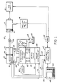
- Fig. 1 illustrates a die casting machine 10 that includes a shot cylinder 12 having a ram 14 for forcing metal from a reservoir 16 into a die cavity 18.
- Ram 14 is coupled to the piston 20 of a hydraulic actuator 22.
- the cylinder 24 of actuator 22 is connected by suitable hydraulic lines to a directional control valve 28 that receives hydraulic fluid from a pump 28, an accumulator 29 and a reservoir 30 under control of a servo or pilot valve 32.
- Directional control valve 26 boosts or amplifies the output flow of valve 32 to a level necessary to operate actuator 22 and ram 14.
- a valve controller 34 supplies valve control signals U and driver signals I (Fig. 5) to the electric motor of servo or pilot valve 32.
- An electro-acoustic sensor 30 is mounted on cylinder 24 of actuator 22 and supplies a signal Ym to valve controller 34 indicative of position of actuator piston 20 within cylinder 24.
- a pair of pressure sensors 38 are responsive to pressure of hydraulic fluid on both sides of actuator piston 20 for supplying corrsponding signals P to controller 42 indicative of fluid pressure.
- An LVDT 40 is coupled to the valve element of directional control valve 26 for supplying a corresponding signal Ys to controller 34 indicative of element position. (In systems of lower hydraulic capacity that do not require a boost valve 26, LVDT 40 may be coupled to the valve element of servo valve 32.)
- a control computer 42 is connected to valve controller 34, preferably by a high-speed bidirectional serial data bus 43, for supplying input command signals to the valve controller and receiving signals from the valve controller indicative of system operation.
- Control computer 42 also receives actuator position signal Ym from sensor 36 through controller 34 and bus 43.
- a programmable logic controller or PLC 44 is connected to control computer 42.
- PLC 44 also controls die cavity 18 for opening and closing the die elements, and reservoir 16 for selectively filling shot cylinder 12.
- An operator console 46 is connected to control computer 42.
- Console 46 includes a screen 48 for graphic display of pressure and velocity profiles as will be described, and a keyboard 50 for operator entry and modification of profile information and other operating parameters.
- keyboard 50 is of standard IBM PC or compatible configuration.
- Directional control valve 26, servo valve 32 and valve controller 34 preferably take the form of a unitary assembly 52 (FIGS. 1-3).
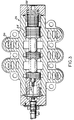
- Valve 26 includes a spool 54 (FIG. 3) mounted within a housing or manifold 56 for controlling the flow of hydraulic fluid through the various manifold control passages.
- a spring 58 is positioned adjacent to one end of spool 54 and urges the spool to a full-reverse position for terminating operation of actuator 22 (FIG. 1) and shot cylinder 12 in the event of system failure.
- LVDT 40 is mounted on housing 56 and has a rod 60 connected to the opposing end of spool 54.
- Servo valve 32 (FIGS. 1 and 2) is mounted by a tap plate 62 on housing 56 of directional control valve 26.
- Tap plate 62 provides for pilot connection to pump 28 and reservoir 30 (FIG. 1). Fluid supply to directional valve 26 and actuator 22 is obtained through manifold 56. Valve 26 has two supply sources: “pump” (FIG. 3) for limited reverse travel and “accumulator” for high-speed extension. Valve controller 34 is mounted on servo valve 32 and has multiple connectors for connection to control computer 42, LVDT 40, pressure sensor 38 and electro-acoustic sensor 36 (FIG. 1).
- U.S. Patent No. 4,757,747 discloses a presently preferred embodiment of controller 34 and servo valve 32 in a unitary assembly that includes microprocessor-based control electronics for providing control signals to the torque motor of valve 32.
- the control electronics disclosed in such patent also includes facility for actuating electro-acoustic sensor 36 and receiving therefrom signals Ym indicative of actuator piston position.
- U.S. Patent No. 4,811,561 discloses an electrohydraulic system that includes actuators with associated servo valves and controllers coupled to a master controller by a high-speed bidirectional serial communication and control bus 43.
- U.S. Patent No. 4,635,682 discloses a valve control system that includes electrohydraulic pilot and main valve stages, and selectable position and flow control loops. The discloses of such U.S. Patents, all assigned to the assignee hereof, are incorporated herein by reference.
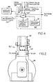
- FIG. 4 is a functional block diagram of control computer 42, which includes a microprocessor 64 having I/O ports for connection to PLC 44, display screen 48 and keyboard 50. Microprocessor 64 is also connected through a serial I/O coupler 66 and through bus 43 to valve controller 34, and receives signals from sensors 38 through an A/D converter 68.
- a program memory 70 such as an EPROM, contains suitable programming and algorithms for operation of computer 42.
- a second memory 72 such as a batteried RAM, provides for storage of multiple velocity/position and ram impact profiles as will be discussed.
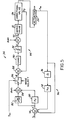
- FIG. 5 is a functional block diagram of valve controller 34 coupled to servo valve 32, directional control valve 26 and actuator 22 in a presently preferred mode of valve controller operation.
- a comparator 74 receives an input load position command signal Yc (from control computer 42 in Fig. 1). Sensor signal Ym is fed to a second input of comparator 74, and through a differentiator 76 and a gain stage 78 to a third comparator input.Comparator 74 thus effectively receives from sensor 36 (Fig.1) a composite signal indicative of actual position at the actuator and load that has been filtered at stages 76, 78 to mask transient variations.
- An output E indicative of the difference or error between desired and actual load position signals, is fed through a gain stage 80 and a deadband jumper 82 to respective inputs of a summing junction 84.
- Jumper 82 helps eliminate error due to lag and non-linearity of valve motion.
- the output of comparator 84 adjusted for actuator bias, is fed to one input of a mode-selection switch 86.
- the second input of switch 86 receives a command signal Ysc from control computer 42 indicative of desired position of directional control valve element 54 (Fig. 3), and the output of switch 86, as a reference or valve command signal R, is fed to a comparator 88.
- Comparator 88 also receives output signal Ys from directional control valve LVDT 40 (Figs.1 and 3) and provides an output as a function of a difference therebetween.
- This output U fed through an appropriate gain stage 90 and deadband jumper 92, and adjusted at 93 for servo and directional valve bias, is supplied as a valve driver signal I to the electric motor of servo valve 32.
- valve controller 34 includes an inner servo control loop 94 that supplies control signals to the torque motor of servo valve 32 as a function of a difference between the valve command input signal R from switch 86 and LVDT sensor signal Ys.
- An outer servo control loop 96 receives load position command Yc, and provides an error signal E as a function of a difference between such load position command signal and actual load position signal Ym.
- Switch 86 connects either error signal E or valve element command signal Ysc to inner loop 94.
- the double-loop control scheme of Fig. 5 provides enhanced versatility and accuracy of control of either the control valve element or actual actuator position.
- Control computer 42 includes menu-driven programming in memory 70 (Fig. 4) for automatic and manual control modes, a shot profile entry/edit mode, and tuning, calibration, system configuration and diagnostic modes of operation.
- profile entry/edit mode of operation the operator is prompted at screen 48 to enter a desired velocity/position profile at keyboard 50.
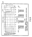
- Fig. 6 illustrates display 48 following entry by the operator of a desired velocity/position profile 100. This profile is entered by movement of the screen cursor 104 among the various incremental position/velocity indicia 102 and entry of appropriate information at keyboard 50.
- the operator has indicted that, at a position of 1.00 inches (25,4 mm) from start of operation, an actuator and ram velocity of 220.00 inches per second (5588 mm/s) is desired.
- This desired velocity is to remain constant up to a position of 18.00 inches (457 mm), followed by a decrease to a velocity of 80.00 inches per second (2032 mm/s) at a position of 19.00 inches (483 mm), constant velocity up to a position of 22.00 inches (559 mm), a decrease at that position to 20.00 inches per second (508 mm/s), and a decrease to zero velocity at the full stroke position of 22.5 inches (571,5 mm). It is thus necessary to enter only points of velocity change.
- Control computer 42 automatically completes profile graph 100 between the selected change points, and displays such profile as illustrated in Fig. 6.
- the operator may shift screen cursor 104 to the appropriate screen location, and enter the corresponding desired change in position or velocity.
- a title 106 is selected by the operator and assigned to the profile, and the profile is stored under that title in memory 72 (Fig. 4) by depression of the ENTER key at keyboard 50. Thereafter, the profile of Fig. 6 may be modified as desired by simply recalling the profile by title (GBNEW in the example of Fig. 6) and entering desired changes.
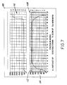
- screen 48 is configured to contain two graphic displays 108, 110 (FIG. 7).
- Display 108 contains superimposed images of desired and actual position/velocity profiles, and display 110 illustrates actual pressure/position profile obtained during system operation.
- the operator selects a preprogrammed velocity/position profile, and this profile 112 is displayed.
- this profile 112 is displayed.
- the operator desires to increase velocity at actuator 22 and shot cylinder 12 (FIG. 1) rapidly to a velocity of 220 inches per second, and to maintain this velocity throughout the entire stroke of 22 inches. (Stroke length is selectable, with different lengths being illustrated in FIGS.
- actuator 22 Upon depression of the F1 function key at keyboard 50, actuator 22 is driver by computer 42 and controller 34 through a complete stroke in the cavity-filling direction 116 (FIG. 1). At each incremental position of actuator piston 20, the corresponding actual velocity is determined as a function of a change in position feedback signal Ym, and the computed velocity is graphically displayed at 114. Likewise, actuator drive pressure P (FIG. 1) is read for incremental display at 110. The operator may thus observe actual versus desired velocity/position profile, as well as changes in hydraulic pressure corresponding to such profile. Desired modifications may be made by returning to the profile editor mode of operation (FIG. 6). Upon completion of a stroke, the shot cylinder and actuator may be retracted to the original or home positions (FIG. 1) by depression of the F2 function key.
- the F3 function key provides for slow execution of a stroke for calibration or maintenance proposes.
- the displays at screen 48 are similar to those illustrated in FIG. 7, with the exception that automatic mode status is displayed along the bottom of the screen rather then the manual function key selections illustrated in FIG. 7.
- Control computer 42 automatically displays actual velocity/position profile 114 and pressure profile 110 of the most recent ten shots, preferably in different colors so that the operator may observe any changes in operation.
- Each "shot” is initiated by a command signal from PLC, which among other functions correspondingly controls reservoir 16 and die cavity 18 (FIG. 1). Status information is transmitted to PLC for management information and control purposes.
- the operator In a calibration mode of operation, the operator has the ability to calibrate the end positions of the actuator, and also to adjust actuator speed through adjustment of fluid flow to the actuator from directional control valve 26. Return velocity of actuator 22 and ram 14 are preferably constant, and set at this point. Likewise, in a system configuration mode of operation, desired maximum velocities, pressure, stroke length and other parameters may be entered by the operator.
- Velocity of the actuator and shot cylinder at the end of a cavity-filling stroke, and thus impact of the shot cylinder when the cavity is full, may be adjusted to reduce separation of the die elements and consequent flash of material out of the die. This is accomplished by selection of the desired impact level (0 through 9) in the configuration mode, the shot profile entry/edit mode or the automatic mode.
- the selected value corresponds to a predefined acceleration profile near the end of the stroke. This profile is based upon the actual position of actuator 22 and/or the pressure signals from sensors 38.
Landscapes
- Engineering & Computer Science (AREA)
- Mechanical Engineering (AREA)
- Manufacturing & Machinery (AREA)
- Physics & Mathematics (AREA)
- General Physics & Mathematics (AREA)
- Automation & Control Theory (AREA)
- Human Computer Interaction (AREA)
- Injection Moulding Of Plastics Or The Like (AREA)
- Fluid-Pressure Circuits (AREA)
- Moulds For Moulding Plastics Or The Like (AREA)
- Feedback Control In General (AREA)
- Programmable Controllers (AREA)
- Servomotors (AREA)
Description
- The present invention is directed to an electrohydraulic system according to the preamble of
claim 1. Control of motion is particularly important in a die casting machine where the control of the ram velocity of the shot cylinder is desired. - Electrohydraulic systems of the preamble to claim 1 are known (US-A-4,757,747). Also known is a hydraulic valve with feedback including two sensors (US-A-4,635,682) which sense the position and the flow of the valve. A compare circuit decides, which of the signals indicating flow or position, is effective for the feedback control of the valve.
- There are numerous applications in the electrohydraulic control field in which it is desired to control motion at an actuator system and load. In a die casting machine, for example, it is desirable closely to control the profile of motion at the so-called shot cylinder that pushes molten metal into the machine die cavity. Specifically, velocity of the shot cylinder ram must be closely controlled as a function of ram position to obtain optimum machine efficiency and throughput, while maintaining product quality and reducing material waste through die separation and flashing, etc. Wear at the cylinder and die cavity are also reduced, and machine productivity therefore increased, when both velocity and stroke of the shot cylinder ram can be closely controlled and tailored to die cavity volume and configuration.
- It is therefore a general object of the present invention to provide an electrohydraulic actuator system that obtains enhanced and precise control of motion at the actuator and load. This problem is solved by the teaching of
claim 1. An advantage of the present invention is that the system embodies state-of-the-art electronic control capability, and yet is easy and economical to implement both in new system construction and in retrofit of existing systems. - Further developments are set forth in the dependent claims. These include an electrohydraulic system for controlling velocity at an actuator load, such as the shot cylinder of a die casting machine, as a precise yet programmable function of position. A related feature of the invention is to provide a shot cylinder control system for a die casting machine that includes facility for programming and storing a plurality of operator-selectable velocity versus position control profiles, for adjustment of impact force at the end of the ram stroke for reducing die separation and flashing at the machine, and/or for graphic display of desired and/or actual velocity profile at the hydraulic cylinder and ram. Yet another advantage of the invention is that the control system employs PC-compatible or other conventional hardware familiar to the operator, and user-friendly state-of-the-art control programming that is easy to employ and yet features enhanced control precision and versatility.
- The electrohydraulic system for controlling motion at a load coupled to a hydraulic actuator in accordance with a first important aspect of the present invention includes an electrohydraulic valve having a valve element. Hydraulic fluid is supplied to the actuator as a function of position of the valve element, which in turn is controlled by electronic valve control signals supplied to the valve. A first position sensor is coupled to the actuator for providing a corresponding signal as a function of motion at the actuator and load. A second position sensor is coupled to the movable element of the valve for providing a corresponding sensor signal as a function of motion at the valve element. Control electronics includes an inner servo loop that supplies control signals to the valve as a function of a differences between a valve command input signal and the signal from the second sensor coupled to the valve element. An outer servo loop supplies a load position error signal as a function of a difference between a load position command input signal and the signal from the first sensor coupled to the actuator and load. A switch is controlled to select between the load position error signal and a separate valve element position command signal to provide the valve command signal to the inner servo loop. Thus, the control electronics, which is preferably microprocessor-based, includes facility for programmed or manual selection of dual control modes of operation for enhanced control flexibility and precision.
- In accordance with a second important aspect of the present invention, the control electronics includes facility for entering a desired profile of velocity versus position or time at the actuator and load. Signals indicative of actual position at the actuator and load are received from the sensor coupled to the load, and corresponding command signals are supplied to the valve for obtaining desired load velocity. Preferably, the control electronics is microprocessor-based and includes facility for receiving and storing a plurality of desired velocity/position profiles and selecting from among the plurality of prestored profiles for operation of the system. Actual velocity/position profile is graphically displayed, preferably superimposed on a graphic display of desired profile for operator observation and adjustment as required.
- In a die casting machine in accordance with a preferred implementation of the invention, which includes a shot cylinder having a ram for injecting metal into a die cavity, an electrohydraulic system for controlling operation of the shot cylinder includes an actuator coupled to the shot cylinder ram. A valve supplies hydraulic fluid to the actuator cylinder as a function of valve control signals. Microprocessor-based digital control electronics includes memory for storing a desired ram velocity profile as an incremental function of ram position. The control circuitry is responsive to signals from a sensor coupled to the actuator indicative of position at the ram for retrieving corresponding velocity signals from memory, and supplying control signals to the valve as a function of such profile velocity signals. The control circuitry further includes facility for adjusting impact of the shot cylinder ram at the end of a cavity-filling stroke as a function of ram and actuator position and/or pressure independently of the velocity/position profile to reduce separation and flashing at the die cavity, and to reduce impact wear and fatigue on the overall die casting machine. A keyboard and associated operator display provide operator programmability and selection from a plurality of velocity/position profiles. The actuator and cylinder ram may be advanced in a manual mode of operation for adjustment and calibration proposes. A display associated with the keyboard graphically illustrates desired and actual velocity/position profiles during operation, together with a profile of actuator drive pressure versus position.
- The invention, together with additional objects, features and advantages thereof, will be best understood from the following description, the appended claims and the accompanying drawings in which:
- FIG. 1 is a functional block diagram of a die casting machine and associated control system in accordance with a presently preferred implementation of the invention;
- FIG. 2 is a side elevational view of the valve and associated controller assembly illustrated functionally in FIG. 1;
- Fig. 3 is a section veiw of the hydraulic directional control valve illustrated in Figs. 1 and 2,
- Fig. 4 is a functional block diagram of the machine control computer in Fig. 1,
- Fig. 5 is a functional block diagram of the valve controller in Fig. 1, and
- Figs. 6 and 7 are graphic illustrations useful in discussing operation of the invention.
- Fig. 1 illustrates a
die casting machine 10 that includes ashot cylinder 12 having aram 14 for forcing metal from areservoir 16 into adie cavity 18. Ram 14 is coupled to thepiston 20 of ahydraulic actuator 22. The cylinder 24 ofactuator 22 is connected by suitable hydraulic lines to adirectional control valve 28 that receives hydraulic fluid from apump 28, anaccumulator 29 and areservoir 30 under control of a servo orpilot valve 32.Directional control valve 26 boosts or amplifies the output flow ofvalve 32 to a level necessary to operateactuator 22 andram 14. Avalve controller 34 supplies valve control signals U and driver signals I (Fig. 5) to the electric motor of servo orpilot valve 32. An electro-acoustic sensor 30 is mounted on cylinder 24 ofactuator 22 and supplies a signal Ym tovalve controller 34 indicative of position ofactuator piston 20 within cylinder 24. A pair ofpressure sensors 38 are responsive to pressure of hydraulic fluid on both sides ofactuator piston 20 for supplying corrsponding signals P to controller 42 indicative of fluid pressure. An LVDT 40 is coupled to the valve element ofdirectional control valve 26 for supplying a corresponding signal Ys to controller 34 indicative of element position. (In systems of lower hydraulic capacity that do not require aboost valve 26,LVDT 40 may be coupled to the valve element ofservo valve 32.) - A
control computer 42 is connected tovalve controller 34, preferably by a high-speed bidirectionalserial data bus 43, for supplying input command signals to the valve controller and receiving signals from the valve controller indicative of system operation.Control computer 42 also receives actuator position signal Ym fromsensor 36 throughcontroller 34 andbus 43. A programmable logic controller orPLC 44 is connected to controlcomputer 42.PLC 44 also controls diecavity 18 for opening and closing the die elements, andreservoir 16 for selectively fillingshot cylinder 12. Anoperator console 46 is connected tocontrol computer 42.Console 46 includes ascreen 48 for graphic display of pressure and velocity profiles as will be described, and akeyboard 50 for operator entry and modification of profile information and other operating parameters. Preferably,keyboard 50 is of standard IBM PC or compatible configuration. -
Directional control valve 26,servo valve 32 andvalve controller 34 preferably take the form of a unitary assembly 52 (FIGS. 1-3). Valve 26 includes a spool 54 (FIG. 3) mounted within a housing ormanifold 56 for controlling the flow of hydraulic fluid through the various manifold control passages. A spring 58 is positioned adjacent to one end ofspool 54 and urges the spool to a full-reverse position for terminating operation of actuator 22 (FIG. 1) and shotcylinder 12 in the event of system failure. LVDT 40 is mounted onhousing 56 and has arod 60 connected to the opposing end ofspool 54. Servo valve 32 (FIGS. 1 and 2) is mounted by atap plate 62 onhousing 56 ofdirectional control valve 26.Tap plate 62 provides for pilot connection to pump 28 and reservoir 30 (FIG. 1). Fluid supply todirectional valve 26 andactuator 22 is obtained throughmanifold 56.Valve 26 has two supply sources: "pump" (FIG. 3) for limited reverse travel and "accumulator" for high-speed extension.Valve controller 34 is mounted onservo valve 32 and has multiple connectors for connection to controlcomputer 42,LVDT 40,pressure sensor 38 and electro-acoustic sensor 36 (FIG. 1). - U.S. Patent No. 4,757,747 discloses a presently preferred embodiment of
controller 34 andservo valve 32 in a unitary assembly that includes microprocessor-based control electronics for providing control signals to the torque motor ofvalve 32. The control electronics disclosed in such patent also includes facility for actuating electro-acoustic sensor 36 and receiving therefrom signals Ym indicative of actuator piston position. U.S. Patent No. 4,811,561 discloses an electrohydraulic system that includes actuators with associated servo valves and controllers coupled to a master controller by a high-speed bidirectional serial communication andcontrol bus 43. U.S. Patent No. 4,635,682 discloses a valve control system that includes electrohydraulic pilot and main valve stages, and selectable position and flow control loops. The discloses of such U.S. Patents, all assigned to the assignee hereof, are incorporated herein by reference. - FIG. 4 is a functional block diagram of
control computer 42, which includes amicroprocessor 64 having I/O ports for connection toPLC 44,display screen 48 andkeyboard 50.Microprocessor 64 is also connected through a serial I/O coupler 66 and throughbus 43 tovalve controller 34, and receives signals fromsensors 38 through an A/D converter 68. Aprogram memory 70, such as an EPROM, contains suitable programming and algorithms for operation ofcomputer 42. Asecond memory 72, such as a batteried RAM, provides for storage of multiple velocity/position and ram impact profiles as will be discussed. - FIG. 5 is a functional block diagram of
valve controller 34 coupled toservo valve 32,directional control valve 26 andactuator 22 in a presently preferred mode of valve controller operation. Acomparator 74 receives an input load position command signal Yc (fromcontrol computer 42 in Fig. 1). Sensor signal Ym is fed to a second input ofcomparator 74, and through adifferentiator 76 and again stage 78 to a thirdcomparator input.Comparator 74 thus effectively receives from sensor 36 (Fig.1) a composite signal indicative of actual position at the actuator and load that has been filtered atstages gain stage 80 and adeadband jumper 82 to respective inputs of a summingjunction 84.Jumper 82 helps eliminate error due to lag and non-linearity of valve motion. The output ofcomparator 84, adjusted for actuator bias, is fed to one input of a mode-selection switch 86. The second input ofswitch 86 receives a command signal Ysc fromcontrol computer 42 indicative of desired position of directional control valve element 54 (Fig. 3), and the output ofswitch 86, as a reference or valve command signal R, is fed to acomparator 88.Comparator 88 also receives output signal Ys from directional control valve LVDT 40 (Figs.1 and 3) and provides an output as a function of a difference therebetween. This output U, fed through anappropriate gain stage 90 anddeadband jumper 92, and adjusted at 93 for servo and directional valve bias, is supplied as a valve driver signal I to the electric motor ofservo valve 32. - Thus,
valve controller 34 includes an inner servo control loop 94 that supplies control signals to the torque motor ofservo valve 32 as a function of a difference between the valve command input signal R fromswitch 86 and LVDT sensor signal Ys. An outer servo control loop 96 receives load position command Yc, and provides an error signal E as a function of a difference between such load position command signal and actual load position signal Ym.Switch 86 connects either error signal E or valve element command signal Ysc to inner loop 94. The double-loop control scheme of Fig. 5 provides enhanced versatility and accuracy of control of either the control valve element or actual actuator position. -
Control computer 42 includes menu-driven programming in memory 70 (Fig. 4) for automatic and manual control modes, a shot profile entry/edit mode, and tuning, calibration, system configuration and diagnostic modes of operation. In the profile entry/edit mode of operation, the operator is prompted atscreen 48 to enter a desired velocity/position profile atkeyboard 50. (The operator also has the option of entering a velocity/time profile.) Fig. 6 illustratesdisplay 48 following entry by the operator of a desired velocity/position profile 100. This profile is entered by movement of thescreen cursor 104 among the various incremental position/velocity indicia 102 and entry of appropriate information atkeyboard 50. In the example of Fig. 6, the operator has indicted that, at a position of 1.00 inches (25,4 mm) from start of operation, an actuator and ram velocity of 220.00 inches per second (5588 mm/s) is desired. This desired velocity is to remain constant up to a position of 18.00 inches (457 mm), followed by a decrease to a velocity of 80.00 inches per second (2032 mm/s) at a position of 19.00 inches (483 mm), constant velocity up to a position of 22.00 inches (559 mm), a decrease at that position to 20.00 inches per second (508 mm/s), and a decrease to zero velocity at the full stroke position of 22.5 inches (571,5 mm). It is thus necessary to enter only points of velocity change.Control computer 42 automatically completesprofile graph 100 between the selected change points, and displays such profile as illustrated in Fig. 6. In the event that a modification is desired, the operator may shiftscreen cursor 104 to the appropriate screen location, and enter the corresponding desired change in position or velocity. Atitle 106 is selected by the operator and assigned to the profile, and the profile is stored under that title in memory 72 (Fig. 4) by depression of the ENTER key atkeyboard 50. Thereafter, the profile of Fig. 6 may be modified as desired by simply recalling the profile by title (GBNEW in the example of Fig. 6) and entering desired changes. - In the manual and automatic modes of operation,
screen 48 is configured to contain twographic displays 108, 110 (FIG. 7).Display 108 contains superimposed images of desired and actual position/velocity profiles, anddisplay 110 illustrates actual pressure/position profile obtained during system operation. Initially, in a manual mode of operation for which an exemplary display is illustrated in FIG. 7, the operator selects a preprogrammed velocity/position profile, and thisprofile 112 is displayed. In theexemplary profile 112, the operator desires to increase velocity atactuator 22 and shot cylinder 12 (FIG. 1) rapidly to a velocity of 220 inches per second, and to maintain this velocity throughout the entire stroke of 22 inches. (Stroke length is selectable, with different lengths being illustrated in FIGS. 6 and 7 for purposes of example.) Upon depression of the F1 function key atkeyboard 50,actuator 22 is driver bycomputer 42 andcontroller 34 through a complete stroke in the cavity-filling direction 116 (FIG. 1). At each incremental position ofactuator piston 20, the corresponding actual velocity is determined as a function of a change in position feedback signal Ym, and the computed velocity is graphically displayed at 114. Likewise, actuator drive pressure P (FIG. 1) is read for incremental display at 110. The operator may thus observe actual versus desired velocity/position profile, as well as changes in hydraulic pressure corresponding to such profile. Desired modifications may be made by returning to the profile editor mode of operation (FIG. 6). Upon completion of a stroke, the shot cylinder and actuator may be retracted to the original or home positions (FIG. 1) by depression of the F2 function key. The F3 function key provides for slow execution of a stroke for calibration or maintenance proposes. - In the automatic mode of operation, selectable by the operator from the main menu at display 48 (FIG. 1), the displays at
screen 48 are similar to those illustrated in FIG. 7, with the exception that automatic mode status is displayed along the bottom of the screen rather then the manual function key selections illustrated in FIG. 7.Control computer 42 automatically displays actual velocity/position profile 114 andpressure profile 110 of the most recent ten shots, preferably in different colors so that the operator may observe any changes in operation. Each "shot" is initiated by a command signal from PLC, which among other functions correspondingly controlsreservoir 16 and die cavity 18 (FIG. 1). Status information is transmitted to PLC for management information and control purposes. - In a calibration mode of operation, the operator has the ability to calibrate the end positions of the actuator, and also to adjust actuator speed through adjustment of fluid flow to the actuator from
directional control valve 26. Return velocity ofactuator 22 and ram 14 are preferably constant, and set at this point. Likewise, in a system configuration mode of operation, desired maximum velocities, pressure, stroke length and other parameters may be entered by the operator. - Velocity of the actuator and shot cylinder at the end of a cavity-filling stroke, and thus impact of the shot cylinder when the cavity is full, may be adjusted to reduce separation of the die elements and consequent flash of material out of the die. This is accomplished by selection of the desired impact level (0 through 9) in the configuration mode, the shot profile entry/edit mode or the automatic mode. The selected value corresponds to a predefined acceleration profile near the end of the stroke. This profile is based upon the actual position of
actuator 22 and/or the pressure signals fromsensors 38.
Claims (19)
- An electrohydraulic system for controlling motion of a load (10) coupled to hydraulic actuation means (22), said system comprising
electrohydraulic valve means (26, 32) that includes a valve element (54), means (56) for supplying hydraulic fluid to said actuation means (22) as a function of position of said valve element (54), and means (32) responsive to electronic valve control signals (U) for controlling position of said valve element (54), and
electronic valve control means (34) that includes first sensor means (36) coupled to said actuator means (22) for providing a first sensor signal (Ym) as a function of motion at the load (10), command means (42) for providing a first command signal (Yc) as a function of desired motion at the load (10), error-signal-providing means (74) for providing an error signal (E) as a function of a difference between said first command signal (Yc) and said first sensor signal (Ym),
characterized in that said electronic valve control means (34) also includes second sensor means (40) coupled to said valve means (26, 32) for providing a second sensor signal (Ys) as a function of motion at said valve element (54), in that said command means (42) also provides a second command signal (Ysc) as a function of desired motion at said valve element (54), in that selecting means (86) is included for selecting between said error signal (E) and said second command signal (Ysc) to provide a command control signal (R), and in that comparator means (88) is included for providing said valve control signal (U) as a function of a difference between said command control signal (R) and said second sensor signal (Ys). - The system set forth in claim 1
wherein said first and second command signals (Yc, Ysc) comprises respective position command signals, and wherein said first and second sensors (36, 40) supply said sensor signals (Ym, Ys) as respective functions of position at said load (10) and said valve element (54). - The system set forth in claim 2
wherein said error-signal providing means (74) includes means (76) for differentiating said first sensor signal (Ym). - The system set forth in claim 2 or 3
wherein said electronic valve control means (34) comprises an inner electronic servo control loop (94) that includes said comparator means (88), and
an outer electronic servo control loop (96) that includes said error-signal providing means (74), said selecting means (86) being provided for receiving said valve element position command signal (Ysc) and selecting between said load position error signal (E) and said valve element position command signal (Ysc) to provide said valve command signal (R) to said inner servo loop (94). - The system set forth in claim 4
wherein said means (76) for differentiating said first sensor signal (Ym) is included in said outer servo control loop (96) to filter said first sensor signal (Ym). - The system set forth in any of claims 1 to 5
further comprising
control means (42) which includes said command means and profile control means for controlling profile of load velocity versus position comprising
entering means (50, 104) for entering a desired profile (100, 112) of velocity versus position at said load,
storing means (72) for receiving and storing said desired profile (100),
receiving means (43, 66) for said first sensor signals (Ym) and
processor means (64) responsive to said receiving-and-storing means (43, 66, 72) for supplying said input command signals (Yc, Ysc) to said valve controller (34). - The system set forth in claim 6
wherein said receiving-and-storing means (43, 66, 72) comprises memory means (72) for receiving and storing a plurality of said desired profiles (100, 112) and profile selecting means (46, 50) for selecting among said plurality of profiles for operation of said system. - The system set forth in claim 6 or 7
further comprising display means (48) for graphically displaying said desired velocity/position profile (100, 112). - The system set forth in claim 8
wherein said display means (48) further includes means (108) responsive to said first sensor signals (Ym) for graphically displaying actual velocity/position profile (114) at said load (10). - The system set forth in claim 9
wherein said graphically-displaying means (48) includes means (108) for displaying said actual profile (114) superimposed on said desired profile (112). - The system set forth in any of claims 1 to 10
further comprising third sensor means (38) for supplying a pressure signal (P) as a function of hydraulic fluid pressure at said actuator (22), and wherein graphically-displaying means (48) further comprises means (64, 66, 68, 110) responsive to said pressure signal (P) and to said first sensor signals (Ym) for displaying profile (110) of pressure versus position at said actuator. - The system set forth in any of claims 6 to 11
wherein said control means (42) further includes means for selectively adjusting velocity or impact at a limit of travel of said load (10) independently of said profile. - The system set forth in any of claims 6 to 12
wherein said control means (42) comprises menu-driven microprocessor-based control means (70). - The system set forth in any of claims 6 to 13
wherein said profile-entering means (50) comprises means (102, 104) for selectively varying parameters of said profile (100). - The system set forth in any of claims 6 to 14
wherein said control means (42) further comprises means (70) for selectively initiating a manual mode of operation, and means for moving said actuator in said manual mode of operation. - The system set forth in any of claims 1 to 15
wherein said load comprises a shot cylinder (12) having a ram (14) for injecting metal into a die cavity (18) of a die casting machine (10). - The system of claim 16
wherein said control means (42) includes means (102, 104) for controlling profile of shot cylinder ram velocity versus position comprising
digital memory means (72) for storing a desired ram velocity profile as an incremental function of ram position,
means (64) coupled to said memory means (72) and responsive to increments of said position-indicative signal (Ym) for retrieving from said memory means corresponding velocity signals, and
means for supplying said valve control signals as a function of said velocity signals. - The system set forth in claim 17
wherein said memory means (72) further includes means for storing adjusted impact control data associated with each said profile. - The system set forth in any of claims 6 to 18
wherein said control means (42) further includes means for optionally entering a desired profile of velocity versus time, and means for supplying said input command signals as a function of said velocity/time profile.
Applications Claiming Priority (2)
| Application Number | Priority Date | Filing Date | Title |
|---|---|---|---|
| US07/341,580 US5289388A (en) | 1989-04-21 | 1989-04-21 | Electrohydraulic control of a die casting machine |
| US341580 | 1989-04-21 |
Publications (3)
| Publication Number | Publication Date |
|---|---|
| EP0393697A2 EP0393697A2 (en) | 1990-10-24 |
| EP0393697A3 EP0393697A3 (en) | 1991-01-23 |
| EP0393697B1 true EP0393697B1 (en) | 1995-06-28 |
Family
ID=23338160
Family Applications (1)
| Application Number | Title | Priority Date | Filing Date |
|---|---|---|---|
| EP90107523A Expired - Lifetime EP0393697B1 (en) | 1989-04-21 | 1990-04-20 | Electrohydraulic system |
Country Status (5)
| Country | Link |
|---|---|
| US (1) | US5289388A (en) |
| EP (1) | EP0393697B1 (en) |
| JP (1) | JPH033003A (en) |
| CN (1) | CN1022855C (en) |
| DE (1) | DE69020415T2 (en) |
Families Citing this family (29)
| Publication number | Priority date | Publication date | Assignee | Title |
|---|---|---|---|---|
| US5092449A (en) * | 1989-12-08 | 1992-03-03 | Liberty Glass Co. | Article transfer apparatus |
| JP2772592B2 (en) * | 1991-08-15 | 1998-07-02 | ファナック株式会社 | Method and apparatus for monitoring injection molding machine |
| WO1993013935A1 (en) * | 1992-01-07 | 1993-07-22 | Signature Technologies, Inc. | Method and apparatus for controlling a press |
| JPH0742705A (en) * | 1993-07-30 | 1995-02-10 | Yutani Heavy Ind Ltd | Hydraulic system of work machine |
| US5500580A (en) * | 1994-09-19 | 1996-03-19 | Hr Textron Inc. | Integrated compliance servovalve |
| US5623093A (en) * | 1995-11-30 | 1997-04-22 | Caterpillar Inc. | Method and apparatus for calibrating an electrohydraulic system |
| US5884894A (en) * | 1996-08-20 | 1999-03-23 | Valtek, Inc. | Inner-loop valve spool positioning control apparatus |
| US6289259B1 (en) * | 1998-10-16 | 2001-09-11 | Husky Injection Molding Systems Ltd. | Intelligent hydraulic manifold used in an injection molding machine |
| DE19953189A1 (en) * | 1999-11-05 | 2001-05-10 | Bosch Gmbh Robert | Control arrangement for a hydraulic or pneumatic system |
| DE102004057878B4 (en) * | 2003-12-08 | 2014-01-23 | Continental Teves Ag & Co. Ohg | Method for calibrating analog controlled hydraulic valves |
| CN100344395C (en) * | 2005-07-28 | 2007-10-24 | 西安重型机械研究所 | Hydraulic system of crystallizer full hydraulic clamping |
| CN100371107C (en) * | 2005-08-08 | 2008-02-27 | 西安重型机械研究所 | Vibrating device hydraulic system |
| CN100343000C (en) * | 2005-11-28 | 2007-10-17 | 深圳领威科技有限公司 | Pressure jetting unit for pressure casting machine and its control method |
| GB0613662D0 (en) | 2006-07-10 | 2006-08-16 | Rotork Controls | Improvements to valve actuators |
| US9457853B2 (en) * | 2013-03-14 | 2016-10-04 | Millenworks | Track tensioner |
| US9999921B2 (en) | 2015-06-15 | 2018-06-19 | Gm Global Technology Operatioins Llc | Method of making aluminum or magnesium based composite engine blocks or other parts with in-situ formed reinforced phases through squeeze casting or semi-solid metal forming and post heat treatment |
| WO2017076430A1 (en) * | 2015-11-03 | 2017-05-11 | Festo Ag & Co. Kg | Application-based control of pneumatic valve assemblies |
| JP6639997B2 (en) * | 2016-03-31 | 2020-02-05 | 住友重機械工業株式会社 | Injection molding machine |
| CN105867304A (en) * | 2016-05-30 | 2016-08-17 | 莱顿汽车部件(苏州)有限公司 | Locking machine with press function and machining method thereof |
| RU2647804C1 (en) * | 2016-12-21 | 2018-03-19 | Общество с ограниченной ответственностью "Газпром трансгаз Томск" (ООО "Газпром трансгаз Томск") | Drive unit with pressure accumulators, method for drive unit control and method for controlling pressure accumulators of a drive unit |
| EP3428461B1 (en) * | 2017-07-14 | 2021-01-20 | Hydraulique Production Systems | Hydraulic cylinder and installation using at least one such hydraulic cylinder |
| CN108626206B (en) * | 2018-05-18 | 2019-12-03 | 太原理工大学 | State parameter acquisition device for electro-hydraulic servo control system |
| EP3657028B1 (en) * | 2018-11-21 | 2023-08-16 | Danfoss Power Solutions Aps | Method for controlling a hydraulic actuator |
| CN111496223B (en) * | 2020-01-19 | 2021-10-29 | 宁波海天金属成型设备有限公司 | A kind of control method and control system of metal liquid entrainment in intelligent pressure chamber of die casting machine |
| JP7234975B2 (en) * | 2020-02-27 | 2023-03-08 | トヨタ自動車株式会社 | Die casting method and die casting apparatus |
| CN111451480B (en) * | 2020-05-15 | 2021-12-21 | 深圳领威科技有限公司 | Electric tilt valve control method, device and equipment of die casting machine and die casting machine |
| JP7556278B2 (en) * | 2020-12-08 | 2024-09-26 | Ubeマシナリー株式会社 | Quality control method for die castings |
| CN114516544B (en) * | 2022-03-14 | 2024-03-15 | 南华大学 | Pneumatic conveying material supply method and supply system |
| CN114680372B (en) * | 2022-05-26 | 2022-11-22 | 南华大学 | Pneumatic conveying control method, computer readable medium, pneumatic conveying control system and tobacco shred pneumatic conveying system |
Family Cites Families (19)
| Publication number | Priority date | Publication date | Assignee | Title |
|---|---|---|---|---|
| US4460324A (en) * | 1981-04-23 | 1984-07-17 | Prince Corporation | Shot cylinder controller for die casting machines and the like |
| US4734869A (en) * | 1981-08-12 | 1988-03-29 | John Mickowski | Diagnostic method for analyzing and monitoring the process parameters in the operation of reciprocating equipment |
| FR2512977A1 (en) * | 1981-09-11 | 1983-03-18 | Thomson Csf | ELECTROHYDRAULIC SERVOVALVE DEVICE |
| JPS58174701A (en) * | 1982-04-07 | 1983-10-13 | Diesel Kiki Co Ltd | Hydraulic actuator device |
| DE3222008A1 (en) * | 1982-06-11 | 1983-12-15 | Sperry-Vickers Zweigniederlassung der Sperry GmbH, 6380 Bad Homburg | HYDROSTATIC OR PNEUMATIC DRIVE AND METHOD FOR ITS OPERATION |
| AU1587183A (en) * | 1982-07-02 | 1984-01-05 | Sperry Corp. | Hydraulic valve with dual feedback control |
| US4486693A (en) * | 1982-07-06 | 1984-12-04 | Contitronix, Inc. | Motor velocity control |
| US4506321A (en) * | 1982-09-08 | 1985-03-19 | Imec Corporation | Motion control system with adaptive deceleration |
| JPS59158237A (en) * | 1983-02-28 | 1984-09-07 | Toshiba Mach Co Ltd | Control apparatus of injection molding apparatus |
| DE3423094A1 (en) * | 1984-06-22 | 1986-01-02 | J. Wagner Gmbh, 7990 Friedrichshafen | METHOD AND DEVICE FOR ADJUSTING A FLOW CONTROL VALVE OF A PAINT SPRAY GUN |
| DE3430654A1 (en) * | 1984-08-21 | 1986-03-06 | Robert Bosch Gmbh, 7000 Stuttgart | FUEL INJECTION PUMP FOR INTERNAL COMBUSTION ENGINES |
| JPS61106219A (en) * | 1984-10-31 | 1986-05-24 | Fanuc Ltd | Monitor circuit for injection molding machine |
| JPS61114832A (en) * | 1984-11-09 | 1986-06-02 | Fanuc Ltd | Injection molding machine capable of monitoring progress |
| JPH0622839B2 (en) * | 1985-04-30 | 1994-03-30 | フアナツク株式会社 | Manual operation method of machine controlled by numerical controller |
| DE3526050C2 (en) * | 1985-07-20 | 1994-11-17 | Krupp Ag Hoesch Krupp | Process for operating an extruder |
| US4757747A (en) * | 1986-04-08 | 1988-07-19 | Vickers, Incorporated | Power transmission |
| US4714005A (en) * | 1986-07-28 | 1987-12-22 | Vickers, Incorporated | Power transmission |
| US5117668A (en) * | 1988-10-17 | 1992-06-02 | Sleeper & Hartley Corp. | Computer controlled coiling machine |
| GB2224370B (en) * | 1988-11-01 | 1993-08-04 | Toshiba Machine Co Ltd | Input display apparatus |
-
1989
- 1989-04-21 US US07/341,580 patent/US5289388A/en not_active Expired - Lifetime
-
1990
- 1990-04-20 DE DE69020415T patent/DE69020415T2/en not_active Expired - Fee Related
- 1990-04-20 JP JP2105135A patent/JPH033003A/en active Pending
- 1990-04-20 EP EP90107523A patent/EP0393697B1/en not_active Expired - Lifetime
- 1990-04-21 CN CN90102379A patent/CN1022855C/en not_active Expired - Fee Related
Also Published As
| Publication number | Publication date |
|---|---|
| US5289388A (en) | 1994-02-22 |
| CN1022855C (en) | 1993-11-24 |
| EP0393697A3 (en) | 1991-01-23 |
| DE69020415D1 (en) | 1995-08-03 |
| EP0393697A2 (en) | 1990-10-24 |
| DE69020415T2 (en) | 1996-02-29 |
| JPH033003A (en) | 1991-01-09 |
| CN1047724A (en) | 1990-12-12 |
Similar Documents
| Publication | Publication Date | Title |
|---|---|---|
| US5289388A (en) | Electrohydraulic control of a die casting machine | |
| EP0332132B1 (en) | Electrohydraulic servo system, especially for injection molding machines | |
| US5316707A (en) | Injection molding apparatus control system and method of injection molding | |
| US4741159A (en) | Power transmission | |
| US6401456B1 (en) | Method and device for controlling work machine | |
| EP0667451B1 (en) | Hydraulic pump control device for construction machinery | |
| EP0193947B1 (en) | Power transmission | |
| DE4327667A1 (en) | Control arrangement for adjustable hydraulic machines | |
| US5540049A (en) | Control system and method for a hydraulic actuator with velocity and force modulation control | |
| EP2657536A1 (en) | Relief pressure control device for hydraulic work machine | |
| KR100476602B1 (en) | Multiple-slide die-casting system | |
| EP0411151B1 (en) | Hydraulic circuit for working machines | |
| EP0812964B1 (en) | Hydraulic actuator operation controller | |
| US4488589A (en) | Shot cylinder controller | |
| EP0402594B1 (en) | Electrohydraulic system | |
| JP2003214351A (en) | Pressure and flow rate control method and apparatus for bidirectional variable discharge pump | |
| GB2099610A (en) | A control device for the hydraulic circuit of an injection moulding machine | |
| JPS60168218A (en) | Flow rate control method | |
| US5079989A (en) | Electrohydraulic valve system with a pressure feedback signal modulated by a velocity feedback signal when the velocity exceeds a veloity limit | |
| JP3172957B2 (en) | Die casting machine control panel | |
| JPH0767607B2 (en) | Cylinder position control method and device | |
| JPH0552248B2 (en) | ||
| JPH0366522B2 (en) | ||
| JPH0361521A (en) | Device and method for controlling injection moldable material into cavity of mold | |
| JPS59127960A (en) | Method and device for injecting with die casting machine |
Legal Events
| Date | Code | Title | Description |
|---|---|---|---|
| PUAI | Public reference made under article 153(3) epc to a published international application that has entered the european phase |
Free format text: ORIGINAL CODE: 0009012 |
|
| AK | Designated contracting states |
Kind code of ref document: A2 Designated state(s): DE FR GB IT SE |
|
| PUAL | Search report despatched |
Free format text: ORIGINAL CODE: 0009013 |
|
| AK | Designated contracting states |
Kind code of ref document: A3 Designated state(s): DE FR GB IT SE |
|
| 17P | Request for examination filed |
Effective date: 19910705 |
|
| 17Q | First examination report despatched |
Effective date: 19930920 |
|
| GRAA | (expected) grant |
Free format text: ORIGINAL CODE: 0009210 |
|
| ITF | It: translation for a ep patent filed | ||
| AK | Designated contracting states |
Kind code of ref document: B1 Designated state(s): DE FR GB IT SE |
|
| REF | Corresponds to: |
Ref document number: 69020415 Country of ref document: DE Date of ref document: 19950803 |
|
| ET | Fr: translation filed | ||
| PLBI | Opposition filed |
Free format text: ORIGINAL CODE: 0009260 |
|
| PG25 | Lapsed in a contracting state [announced via postgrant information from national office to epo] |
Ref country code: SE Effective date: 19960421 |
|
| PLBF | Reply of patent proprietor to notice(s) of opposition |
Free format text: ORIGINAL CODE: EPIDOS OBSO |
|
| 26 | Opposition filed |
Opponent name: MANNESMANN REXROTH GMBH Effective date: 19960326 |
|
| PLBF | Reply of patent proprietor to notice(s) of opposition |
Free format text: ORIGINAL CODE: EPIDOS OBSO |
|
| PLBF | Reply of patent proprietor to notice(s) of opposition |
Free format text: ORIGINAL CODE: EPIDOS OBSO |
|
| PLBF | Reply of patent proprietor to notice(s) of opposition |
Free format text: ORIGINAL CODE: EPIDOS OBSO |
|
| EUG | Se: european patent has lapsed |
Ref document number: 90107523.4 |
|
| PGFP | Annual fee paid to national office [announced via postgrant information from national office to epo] |
Ref country code: FR Payment date: 19970318 Year of fee payment: 8 |
|
| PGFP | Annual fee paid to national office [announced via postgrant information from national office to epo] |
Ref country code: DE Payment date: 19970324 Year of fee payment: 8 |
|
| PGFP | Annual fee paid to national office [announced via postgrant information from national office to epo] |
Ref country code: GB Payment date: 19970326 Year of fee payment: 8 |
|
| PG25 | Lapsed in a contracting state [announced via postgrant information from national office to epo] |
Ref country code: GB Free format text: LAPSE BECAUSE OF NON-PAYMENT OF DUE FEES Effective date: 19980420 |
|
| PG25 | Lapsed in a contracting state [announced via postgrant information from national office to epo] |
Ref country code: FR Free format text: THE PATENT HAS BEEN ANNULLED BY A DECISION OF A NATIONAL AUTHORITY Effective date: 19980430 |
|
| PLBO | Opposition rejected |
Free format text: ORIGINAL CODE: EPIDOS REJO |
|
| PLBN | Opposition rejected |
Free format text: ORIGINAL CODE: 0009273 |
|
| STAA | Information on the status of an ep patent application or granted ep patent |
Free format text: STATUS: OPPOSITION REJECTED |
|
| 27O | Opposition rejected |
Effective date: 19980529 |
|
| GBPC | Gb: european patent ceased through non-payment of renewal fee |
Effective date: 19980420 |
|
| PG25 | Lapsed in a contracting state [announced via postgrant information from national office to epo] |
Ref country code: DE Free format text: LAPSE BECAUSE OF NON-PAYMENT OF DUE FEES Effective date: 19990202 |
|
| REG | Reference to a national code |
Ref country code: FR Ref legal event code: ST |
|
| PG25 | Lapsed in a contracting state [announced via postgrant information from national office to epo] |
Ref country code: IT Free format text: LAPSE BECAUSE OF NON-PAYMENT OF DUE FEES;WARNING: LAPSES OF ITALIAN PATENTS WITH EFFECTIVE DATE BEFORE 2007 MAY HAVE OCCURRED AT ANY TIME BEFORE 2007. THE CORRECT EFFECTIVE DATE MAY BE DIFFERENT FROM THE ONE RECORDED. Effective date: 20050420 |