EP0393157B1 - Arrangement for fixing a knee-joint in defined positions and for positional control of instruments for replacing the knee-joint with a prosthesis - Google Patents
Arrangement for fixing a knee-joint in defined positions and for positional control of instruments for replacing the knee-joint with a prosthesis Download PDFInfo
- Publication number
- EP0393157B1 EP0393157B1 EP19890904660 EP89904660A EP0393157B1 EP 0393157 B1 EP0393157 B1 EP 0393157B1 EP 19890904660 EP19890904660 EP 19890904660 EP 89904660 A EP89904660 A EP 89904660A EP 0393157 B1 EP0393157 B1 EP 0393157B1
- Authority
- EP
- European Patent Office
- Prior art keywords
- joint
- knee
- fixing
- fixation
- arrangement
- Prior art date
- Legal status (The legal status is an assumption and is not a legal conclusion. Google has not performed a legal analysis and makes no representation as to the accuracy of the status listed.)
- Expired - Lifetime
Links
- 210000000629 knee joint Anatomy 0.000 title claims abstract description 41
- 210000002303 tibia Anatomy 0.000 claims abstract description 21
- 210000000689 upper leg Anatomy 0.000 claims abstract description 14
- 238000006073 displacement reaction Methods 0.000 claims abstract description 11
- 210000003414 extremity Anatomy 0.000 claims description 8
- 210000000544 articulatio talocruralis Anatomy 0.000 claims description 7
- 238000001356 surgical procedure Methods 0.000 abstract description 4
- 210000002414 leg Anatomy 0.000 description 10
- 238000004873 anchoring Methods 0.000 description 7
- 210000000988 bone and bone Anatomy 0.000 description 6
- 230000007246 mechanism Effects 0.000 description 5
- 210000003423 ankle Anatomy 0.000 description 4
- 210000001699 lower leg Anatomy 0.000 description 3
- 210000001981 hip bone Anatomy 0.000 description 2
- 210000003127 knee Anatomy 0.000 description 2
- 238000000034 method Methods 0.000 description 2
- 238000011477 surgical intervention Methods 0.000 description 2
- 238000010276 construction Methods 0.000 description 1
- 230000000694 effects Effects 0.000 description 1
- 238000005516 engineering process Methods 0.000 description 1
- 210000004394 hip joint Anatomy 0.000 description 1
- 238000002513 implantation Methods 0.000 description 1
- 238000004519 manufacturing process Methods 0.000 description 1
- 238000005259 measurement Methods 0.000 description 1
- 238000010883 osseointegration Methods 0.000 description 1
- 239000000523 sample Substances 0.000 description 1
- 238000012216 screening Methods 0.000 description 1
- 230000000472 traumatic effect Effects 0.000 description 1
Images




Classifications
-
- A—HUMAN NECESSITIES
- A61—MEDICAL OR VETERINARY SCIENCE; HYGIENE
- A61F—FILTERS IMPLANTABLE INTO BLOOD VESSELS; PROSTHESES; DEVICES PROVIDING PATENCY TO, OR PREVENTING COLLAPSING OF, TUBULAR STRUCTURES OF THE BODY, e.g. STENTS; ORTHOPAEDIC, NURSING OR CONTRACEPTIVE DEVICES; FOMENTATION; TREATMENT OR PROTECTION OF EYES OR EARS; BANDAGES, DRESSINGS OR ABSORBENT PADS; FIRST-AID KITS
- A61F5/00—Orthopaedic methods or devices for non-surgical treatment of bones or joints; Nursing devices ; Anti-rape devices
- A61F5/01—Orthopaedic devices, e.g. long-term immobilising or pressure directing devices for treating broken or deformed bones such as splints, casts or braces
- A61F5/04—Devices for stretching or reducing fractured limbs; Devices for distractions; Splints
-
- A—HUMAN NECESSITIES
- A61—MEDICAL OR VETERINARY SCIENCE; HYGIENE
- A61F—FILTERS IMPLANTABLE INTO BLOOD VESSELS; PROSTHESES; DEVICES PROVIDING PATENCY TO, OR PREVENTING COLLAPSING OF, TUBULAR STRUCTURES OF THE BODY, e.g. STENTS; ORTHOPAEDIC, NURSING OR CONTRACEPTIVE DEVICES; FOMENTATION; TREATMENT OR PROTECTION OF EYES OR EARS; BANDAGES, DRESSINGS OR ABSORBENT PADS; FIRST-AID KITS
- A61F2/00—Filters implantable into blood vessels; Prostheses, i.e. artificial substitutes or replacements for parts of the body; Appliances for connecting them with the body; Devices providing patency to, or preventing collapsing of, tubular structures of the body, e.g. stents
- A61F2/02—Prostheses implantable into the body
- A61F2/30—Joints
- A61F2/46—Special tools for implanting artificial joints
- A61F2/4603—Special tools for implanting artificial joints for insertion or extraction of endoprosthetic joints or of accessories thereof
- A61F2/461—Special tools for implanting artificial joints for insertion or extraction of endoprosthetic joints or of accessories thereof of knees
-
- A—HUMAN NECESSITIES
- A61—MEDICAL OR VETERINARY SCIENCE; HYGIENE
- A61B—DIAGNOSIS; SURGERY; IDENTIFICATION
- A61B17/00—Surgical instruments, devices or methods
- A61B17/14—Surgical saws
- A61B17/15—Guides therefor
Definitions
- the present invention relates to an arrangement for fixing a knee-joint in defined positions and for positional control of instruments for replacing the knee-joint of a patient with a prosthesis, which arrangement is designed to be connected to an operating table intended to support the patient, according to the preamble of Claim 1.
- the aim of the present invention is to provide a technique for exact atraumatic cutting of bone ends constituting a seat for the knee prosthesis which, by means of the arrangement, can be placed in the desired position.
- the arrangement comprises, on the one hand, a stand which can be connected to the operating table, an alignment instrument which is supported by the stand and is used for aligning both the femur and tibia relative to a reference axis, and, on the other hand, a positional control unit which can be connected to the stand in defined positions and is used for positional control of at least one instrument relative to the knee-joint,
- which alignment instrument comprises a fixture, supported by the stand, for the trunk of the patient, which trunk fixture is adjustable and can be locked in selected positions by displacement transverse to the said reference axis, and a limb fixture, supported by the stand, for fixing the knee-joint and ankle-joint of the patient, in that the said limb fixture for fixing the knee-joint and ankle-joint consists of a fixation frame which is pivotably mounted on the stand by means of a pivot hinge and which, by means of its pivotability, can be set in different
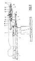
- Fig. 1 shows a plan view of an alignment instrument incorporated in the arrangement according to the invention
- Fig. 2 shows the alignment instrument set in an operating position
- Fig. 3 shows the arrangement with the alignment instrument and a cutting and assembly tool connected to it
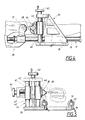
- Figs. 4 and 5 show two different views of the cutting and assembly tool on a larger scale
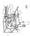
- Fig. 6 shows a perspective view of the alignment instrument supplemented with a positional control unit for a second cutting instrument according to the invention
- Fig. 7 shows a separate side view of the positional control unit with the said cutting instrument
- Fig. 8 shows a side view of an operating table with the patient, and with the arrangement according to the invention in operation.
- the arrangement according to the invention forms a unit which can be integrated with a conventional operating table 1, as is shown, for example, in Figs. 1 and 2.
- the arrangement can either be designed as a separate additional element, which can be assembled subsequently on existing operating tables, or can from the start be integrated with operating tables specially designed for the type of surgical intervention in question, which in this case is knee-joint replacement.
- the arrangement according to the invention comprises an alignment instrument 2 and a stand 3, fixed at the bottom end of the operating table, in which respect the alignment instrument has a fixture 4 for the trunk of the patient.
- the fixture 4 comprises a slide 5 which can be displaced relative to the stand 3 transverse to the longitudinal direction of the patient.
- the displacement movement is made possible by means of a guide arrangement 6 which, in the example shown, is made up of two parallel bars 7, which are at least partially surrounded by runner members 8 connected to the slide 5.
- a locking arrangement in connection with at least one of the runner members, the slide 5 can be locked in a chosen lateral displacement position.
- This locking arrangement can be of a type conventional per se, for example with clamping members which lock against the associated rod with frictional locking.
- the slide 5 has two padded hip-positioning members 9 which, by means of an adjustable attachment 10, can be adjusted so as to vary the space between the positioning members 9 between different positions in the longitudinal direction of the patient.
- the attachments 10 are moreover designed so that they automatically take up an angular position adapted to the contour of the patient.
- the arrangement described thus forms an adjustable fixture 4 for the trunk or hip-bones of the patient, which parts of the body can therefore be moved sideways and fixed in a defined position.
- the alignment instrument 2 furthermore comprises an adjustable limb fixture 11.
- this fixture will be referred to from now on as the leg fixture 11.
- the leg fixture consists of a fixation frame which is pivotably mounted relative to the stand 3 and, thus, also to the operating table 1, and whose pivoting movement takes place about a pivot hinge 13 adapted to the range of movement of the knee-joint.
- the pivot hinge 13 extends transverse to the longitudinal direction of the operating table and the patient. It determines the pivoting movement of the leg fixture, which movement takes place in the sagittal plane of the leg. In this way the lower leg 12 of the patient can be swung in a defined plane relative to a fixed reference axis.
- the pivot hinge is placed at such a height and is supported by two brackets 14 on the stand in such a way that the thigh 15 of the patient is held essentially horizontal.
- the angle of the femur relative to a horizontal axis can suitably be set by means of a height-adjusting mechanism (not shown) for the trunk fixture 4.
- the fixation frame essentially consists of two guide bars 16 which run parallel to each other at such a distance that the lower leg 12 of the patient is accommodated between these with a necessary margin for lateral movement.
- the leg fixture 11 has three fixation members 17, 18, 19, namely a first fixation member 17 for fixing the knee-joint part 20 belonging to the femur 66, a second fixation member 18 for fixing the upper end of the tibia 21 and, thus, the knee-joint part 22 belonging to the tibia, and a third fixation member 19 for fixing the lower end 23 of the lower leg, i.e. essentially the ankle.
- the first two fixation members 17, 18 expediently consist of rod elements which are either driven completely through the bone tissue or are driven in to bear against the femur or tibia.
- fixation members 17, 18 are adjustably fixed on the fixation frame 11 by means of displaceable runner members 24, 25 in the form of, for example, sleeve-shaped elements which can be moved along the guide bars and which can be locked, by means of locking members, at selected positions along the guide bars.
- the runner members have transverse openings through which the rod elements extend.
- the third fixation member has an element, for example in the form of a rod 26, extending between the guide bars in conformity with the direction of the rod elements, which rod 26 is likewise supported by two runner members 27, of the same type as support the first two fixation members, and can be locked in a corresponding manner.
- the transverse element 26 has a holder element which constitutes the fixation member and which is padded to bear against the ankle.
- the element is advantageously adjustable in such a way that it can be adapted to different sizes of ankle, or alternatively the holder element is designed to permit secure positional holding regardless of the dimensions of the ankle.
- the position of the lower part of the tibia can be adjusted sideways by means of a lockable adjustment device, which can comprise a locking arrangement known per se for the transverse element 26, which can be moved sideways in the associated runner members 27.
- the fixation instrument 11 also includes a stretching device 29 (tensor), an example of whose construction is shown in Fig. 2.
- the stretching device is designed as a tensile screw 30 for each guide bar 16, which bars are axially displaceable in a mounting 31 which is connected to the pivot hinge 13.
- the tensile screw 30 is threaded in the mounting and is displaced axially relative to this by means of screwing and thus acts on the end of the associated guide bar 16.
- the tibia 21 can be stretched in order thereby to separate the parts of the knee-joint, as is necessary in surgery of the knee-joint.
- the fixation frame 11 and, thus, the tibia 21 can be set in different angular positions relative to the main plane of the operating table 1, i.e. the normal horizontal plane and the frontal plane of the patient.
- the tibia can thus be swung in the sagittal plane of the leg.
- the fixation frame 11 can be locked in the chosen angular position by means of a locking device on the pivot hinge 13 which, in the simplest case, can be made up of a locking pin which locks through locking holes 32 situated opposite each other in the mounting 31 and the bracket 14, in which respect, for example, the bracket has a number of alternative holes for different angular positions.
- the locking device can consist of a mechanism known per se for frictional locking, where secure clamping on the axle of the pivot hinge is effected, for example, by a locking screw. This can be supplemented by angle-reading (not shown), for example a graduated arc for confirming the correct angular position.
- the important positions for knee-joint replacement are essentially the position in which the leg is straight according to Fig. 1, and in which the leg is bent according to Fig. 2.
- the knee-joint 20, 22 is fixed by means of alignment of the limb 12 which is to be treated.
- This fixation is carried out in order to achieve a well-defined, fixed position of the tibia 21 and femur 66 with respect to each other and relative to the stand 3, which defines a reference position in space so that a correct surgical intervention can be performed with accurate cutting and with correct assembly of the joint prosthesis.
- the knee-joint parts 20, 22 of the femur 66 and tibia 21 are thus fixed by means of fixation members 17, 18, and the lower end 23 of the tibia is fixed in the third fixation member 19, and the trunk is fixed in its support device 4 by tightening and locking the hip-positioning members 9 against the hip-bones.
- the femur 66 is aligned relative to the tibia 21 by means of lateral displacement of the trunk, which is achieved by moving the slide 5 of the support device 4. This is expediently carried out with x-ray screening of the limb and checking that the desired geometry has been achieved.
- the centre of the knee-joint parts 20, 22 is in a straight line between the centre of the hip-joint 33 and the centre of the ankle-joint.
- the said alignment is carried out by fixing the tibia and moving the femur 66 by means of lateral displacement of the trunk of the patient, which is achieved by moving the support device 4 on the guide device 6 and locking it in the selected position.
- a lesser lateral adjustment can also be obtained by moving the lower end 23 of the tibia sideways by means of the fixation member 19 being laterally displaced and locked in the chosen position.
- the trunk can also advantageously be moved vertically by raising and lowering the support device 4 by means of a mechanism which can vary the vertical distance of the support device from the guide device 6.
- the arrangement according to the invention comprises, in addition to the alignment instrument 2, cutting equipments for surgical treatment of the knee-joint.
- Certain types of knee-joint prostheses have anchoring elements intended to be anchored in the knee-joint parts of the femur or tibia from the side.
- a cutting and assembly tool 34 is incorporated in the arrangement according to the invention, which tool is shown in Fig. 3 mounted on the alignment instrument 2 and, more specifically, on the two guide bars 16 of the fixation frame 11.
- An example of the cutting instrument 34 is shown on a larger scale in Figs.
- the cutting tool consists of a rotating, for example electrically or pneumatically driven, machine 38 which rotates a drill 39 or a cutter in order to produce a channel in the bone tissue for the anchoring element.
- the rotating machine 38 is supported by a tool holder 40 designed to set the cutting tool in the desired position both vertically and horizontally. This is achieved by means of setting mechanisms for both the vertical and horizontal directions.
- these consist of a vertical shaft 41 and a horizontal shaft 42 which are threaded and can be rotated by means of rotating wheels 43, 44.
- the holder 40 has a part 45 which can be moved vertically by means of the screw shaft 41 and which in turn has a part 46 which can be moved horizontally by means of the screw shaft 42 and which in turn supports the rotating machine.
- a complete adjustability of the cutting tool in the vicinity of the knee-joint is thus obtained in three coordinate axes at right angles to each other.
- the cutting is preceded by a precise setting of the tool to the correct position in front of the cutting site. Thereafter, the tool is put into operation and is moved successively along the shaft 42 to a chosen position, which is read off on a length scale.
- the arrangement according to the invention also includes a positional control unit 47 for a measuring and cutting instrument 48.
- This instrument is intended to produce with high precision, in the knee-joint parts of both the femur and tibia, an atraumatic cutting of the bone tissue in order to permit osseointegration with the joint prosthesis.
- This positional control unit 47 consists of an additional frame which is arranged on specially provided attachment devices 49 on the stand 3. In the example shown, these consist of four sleeve-shaped units which are arranged securely on the stand and in each case have a locking device 50 for locking the positional control unit, which has four legs intended to be moved down and locked in the attachment device by means of, for example, locking screws or locking pins.
- the positional control unit 47 is intended to be arranged with the fixation frame 11 of the alignment instrument swung down, and is made up of three sets of guide arrangements 51, 52, 53 which extend at right angles to each other and are supported by a stand 54, which is secured in the attachment devices 49.
- the three guide arrangements are directed at right angles to each other along three coordinate axes at right angles to each other in order to permit, within a necessary range, the adjustment of the measuring and cutting tool 48 in each desired position in space.
- the measuring and cutting tool 48 is in reality two separate tools, which can be arranged exchangeably on the slide 57 so as to be used in two separate moments, the measuring tool being used during a measuring moment and the cutting tool being used during a cutting moment.
- the measuring tool consists of a conventional measuring probe with associated surrounding equipment and is arranged on the slide 57. Exact measurement of the surface geometry of the knee-joint and, thus, its condition gives the value for its subsequent cutting.
- the cutting tool consists of a rotating machine 59 in the form of a drill with variable speed.
- the slide 55 and, thus, also the remaining slides 56, 57 are roughly adjusted as regards the displacement in the horizontal plane, i.e. in the direction to or from the knee-joint of the patient. This is achieved by means of a manual displacement of the slide and a locking in a suitable starting position by means of a locking device 60.
- the displacement movement for the other slides relative to the first slide is achieved by means of separate adjusting mechanisms 61, 62, 63 which, in the example shown, consist of screw axes which are rotated by means of manoeuvring knobs 64.
- the slide 56 can moreover be locked by means of a locking device 65.
- the positional control unit 47 described above allows for cutting with high precision, in which respect tools can be set with great precision in predetermined positions relative to the knee-joint. Plane and also perpendicular cutting surfaces are obtained simply by virtue of the fact that the cutting tool can be moved in one plane at a time.
- the above description has not dealt with the moments which relate to assembly of the anchoring element or prosthesis parts, the sequence of which depends on the actual procedure.
- the assembly of the anchoring elements can, for example, be effected by using the associated cutting tools.
- the remaining assembly can be effected with the positional control unit 47 removed, but expediently with the leg still aligned by means of the alignment instrument.
- the invention is not limited to the exemplary embodiment described above and shown in the drawings, but can be varied within the scope of the subsequent patent claims.
- the cutting tool shown in Figs. 3, 4 and 5 can be omitted and replaced by the cutting tool shown in Figs. 6, 7 and 8.
- the positional control unit 47 can be designed in a number of different ways in order to permit a positional control of the cutting tool in space.
- Both the cutting tools can, for example, be designed to be turned and, thus, set at an angle relative to the horizontal plane and/or vertical plane in order to permit an angled positioning of the anchoring elements or inclined cutting surfaces.
Landscapes
- Health & Medical Sciences (AREA)
- Orthopedic Medicine & Surgery (AREA)
- Animal Behavior & Ethology (AREA)
- General Health & Medical Sciences (AREA)
- Biomedical Technology (AREA)
- Heart & Thoracic Surgery (AREA)
- Vascular Medicine (AREA)
- Life Sciences & Earth Sciences (AREA)
- Transplantation (AREA)
- Engineering & Computer Science (AREA)
- Public Health (AREA)
- Veterinary Medicine (AREA)
- Physical Education & Sports Medicine (AREA)
- Nursing (AREA)
- Cardiology (AREA)
- Oral & Maxillofacial Surgery (AREA)
- Prostheses (AREA)
- Surgical Instruments (AREA)
Abstract
Description
- The present invention relates to an arrangement for fixing a knee-joint in defined positions and for positional control of instruments for replacing the knee-joint of a patient with a prosthesis, which arrangement is designed to be connected to an operating table intended to support the patient, according to the preamble of Claim 1.
- Such an arrangement is known from US-A-4 574 794.
- In connection with the implantation of knee-joint prostheses in knee-joints for prosthetic surgery of the knee, relatively primative means are used for fixing the knee-joint and for positional control of the surgical instrument. Previously known arrangements involve very inexact cutting of those parts which are to be removed in the operation. Furthermore, in many cases the operating time is unfavourably long and results in high heat production, with the risk of the patient suffering traumatic effects. A very important disadvantage with the known arrangements is that the poor precision in cutting of the bone tissue results in an inexact fitting between prosthesis and bone, which can jeopardize the anchoring of the prosthesis. The previously known technology has mainly been used for knee-joint replacements in patients with low activity, such as persons older than about 60 years of age. Even in these cases, knee-joint replacement has involved a limited prosthesis life.
- The aim of the present invention is to provide a technique for exact atraumatic cutting of bone ends constituting a seat for the knee prosthesis which, by means of the arrangement, can be placed in the desired position.
- The said aim is achieved by means of an arrangement according to the present invention, which is characterized in that the arrangement comprises, on the one hand, a stand which can be connected to the operating table, an alignment instrument which is supported by the stand and is used for aligning both the femur and tibia relative to a reference axis, and, on the other hand, a positional control unit which can be connected to the stand in defined positions and is used for positional control of at least one instrument relative to the knee-joint, which alignment instrument comprises a fixture, supported by the stand, for the trunk of the patient, which trunk fixture is adjustable and can be locked in selected positions by displacement transverse to the said reference axis, and a limb fixture, supported by the stand, for fixing the knee-joint and ankle-joint of the patient, in that the said limb fixture for fixing the knee-joint and ankle-joint consists of a fixation frame which is pivotably mounted on the stand by means of a pivot hinge and which, by means of its pivotability, can be set in different angular positions relative to the operating table.
- The invention will be illustrated in greater detail below on the basis of an exemplary embodiment and with reference to the attached drawings, in which Fig. 1 shows a plan view of an alignment instrument incorporated in the arrangement according to the invention, Fig. 2 shows the alignment instrument set in an operating position, Fig. 3 shows the arrangement with the alignment instrument and a cutting and assembly tool connected to it, while Figs. 4 and 5 show two different views of the cutting and assembly tool on a larger scale. Fig. 6 shows a perspective view of the alignment instrument supplemented with a positional control unit for a second cutting instrument according to the invention, Fig. 7 shows a separate side view of the positional control unit with the said cutting instrument, and Fig. 8 shows a side view of an operating table with the patient, and with the arrangement according to the invention in operation.
- The arrangement according to the invention forms a unit which can be integrated with a conventional operating table 1, as is shown, for example, in Figs. 1 and 2. The arrangement can either be designed as a separate additional element, which can be assembled subsequently on existing operating tables, or can from the start be integrated with operating tables specially designed for the type of surgical intervention in question, which in this case is knee-joint replacement. The arrangement according to the invention comprises an
alignment instrument 2 and astand 3, fixed at the bottom end of the operating table, in which respect the alignment instrument has a fixture 4 for the trunk of the patient. As emerges most clearly from Fig. 1, the fixture 4 comprises aslide 5 which can be displaced relative to thestand 3 transverse to the longitudinal direction of the patient. The displacement movement is made possible by means of aguide arrangement 6 which, in the example shown, is made up of twoparallel bars 7, which are at least partially surrounded byrunner members 8 connected to theslide 5. By means of a locking arrangement in connection with at least one of the runner members, theslide 5 can be locked in a chosen lateral displacement position. This locking arrangement can be of a type conventional per se, for example with clamping members which lock against the associated rod with frictional locking. Theslide 5 has two padded hip-positioning members 9 which, by means of anadjustable attachment 10, can be adjusted so as to vary the space between thepositioning members 9 between different positions in the longitudinal direction of the patient. Theattachments 10 are moreover designed so that they automatically take up an angular position adapted to the contour of the patient. The arrangement described thus forms an adjustable fixture 4 for the trunk or hip-bones of the patient, which parts of the body can therefore be moved sideways and fixed in a defined position. - The
alignment instrument 2 furthermore comprises anadjustable limb fixture 11. For the sake of simplicity, this fixture will be referred to from now on as theleg fixture 11. The leg fixture consists of a fixation frame which is pivotably mounted relative to thestand 3 and, thus, also to the operating table 1, and whose pivoting movement takes place about apivot hinge 13 adapted to the range of movement of the knee-joint. Thepivot hinge 13 extends transverse to the longitudinal direction of the operating table and the patient. It determines the pivoting movement of the leg fixture, which movement takes place in the sagittal plane of the leg. In this way thelower leg 12 of the patient can be swung in a defined plane relative to a fixed reference axis. The pivot hinge is placed at such a height and is supported by twobrackets 14 on the stand in such a way that thethigh 15 of the patient is held essentially horizontal. The angle of the femur relative to a horizontal axis can suitably be set by means of a height-adjusting mechanism (not shown) for the trunk fixture 4. The fixation frame essentially consists of twoguide bars 16 which run parallel to each other at such a distance that thelower leg 12 of the patient is accommodated between these with a necessary margin for lateral movement. Theleg fixture 11 has threefixation members first fixation member 17 for fixing the knee-joint part 20 belonging to thefemur 66, asecond fixation member 18 for fixing the upper end of thetibia 21 and, thus, the knee-joint part 22 belonging to the tibia, and athird fixation member 19 for fixing thelower end 23 of the lower leg, i.e. essentially the ankle. The first twofixation members fixation members fixation frame 11 by means ofdisplaceable runner members rod 26, extending between the guide bars in conformity with the direction of the rod elements, whichrod 26 is likewise supported by tworunner members 27, of the same type as support the first two fixation members, and can be locked in a corresponding manner. Thetransverse element 26 has a holder element which constitutes the fixation member and which is padded to bear against the ankle. The element is advantageously adjustable in such a way that it can be adapted to different sizes of ankle, or alternatively the holder element is designed to permit secure positional holding regardless of the dimensions of the ankle. As indicated by the two-way arrow 28, the position of the lower part of the tibia can be adjusted sideways by means of a lockable adjustment device, which can comprise a locking arrangement known per se for thetransverse element 26, which can be moved sideways in the associatedrunner members 27. - The
fixation instrument 11 also includes a stretching device 29 (tensor), an example of whose construction is shown in Fig. 2. The stretching device is designed as atensile screw 30 for eachguide bar 16, which bars are axially displaceable in amounting 31 which is connected to thepivot hinge 13. Thetensile screw 30 is threaded in the mounting and is displaced axially relative to this by means of screwing and thus acts on the end of the associatedguide bar 16. Thus, by means of thestretching device 29, thetibia 21 can be stretched in order thereby to separate the parts of the knee-joint, as is necessary in surgery of the knee-joint. - As a result of its pivotability about the
hinge 13, thefixation frame 11 and, thus, thetibia 21 can be set in different angular positions relative to the main plane of the operating table 1, i.e. the normal horizontal plane and the frontal plane of the patient. The tibia can thus be swung in the sagittal plane of the leg. Thefixation frame 11 can be locked in the chosen angular position by means of a locking device on thepivot hinge 13 which, in the simplest case, can be made up of a locking pin which locks throughlocking holes 32 situated opposite each other in themounting 31 and thebracket 14, in which respect, for example, the bracket has a number of alternative holes for different angular positions. Alternatively, the locking device can consist of a mechanism known per se for frictional locking, where secure clamping on the axle of the pivot hinge is effected, for example, by a locking screw. This can be supplemented by angle-reading (not shown), for example a graduated arc for confirming the correct angular position. - The important positions for knee-joint replacement are essentially the position in which the leg is straight according to Fig. 1, and in which the leg is bent according to Fig. 2. In the position according to Fig. 1, i.e. with the
fixation frame 11 and thetibia 21 horizontal, the knee-joint limb 12 which is to be treated. This fixation is carried out in order to achieve a well-defined, fixed position of thetibia 21 andfemur 66 with respect to each other and relative to thestand 3, which defines a reference position in space so that a correct surgical intervention can be performed with accurate cutting and with correct assembly of the joint prosthesis. The knee-joint parts femur 66 andtibia 21 are thus fixed by means offixation members lower end 23 of the tibia is fixed in thethird fixation member 19, and the trunk is fixed in its support device 4 by tightening and locking the hip-positioning members 9 against the hip-bones. Thereafter, thefemur 66 is aligned relative to thetibia 21 by means of lateral displacement of the trunk, which is achieved by moving theslide 5 of the support device 4. This is expediently carried out with x-ray screening of the limb and checking that the desired geometry has been achieved. For example, in a normal case, it is desirable for the centre of the knee-joint parts joint 33 and the centre of the ankle-joint. The said alignment is carried out by fixing the tibia and moving thefemur 66 by means of lateral displacement of the trunk of the patient, which is achieved by moving the support device 4 on theguide device 6 and locking it in the selected position. A lesser lateral adjustment can also be obtained by moving thelower end 23 of the tibia sideways by means of thefixation member 19 being laterally displaced and locked in the chosen position. As has been mentioned above, the trunk can also advantageously be moved vertically by raising and lowering the support device 4 by means of a mechanism which can vary the vertical distance of the support device from theguide device 6. - The arrangement according to the invention comprises, in addition to the
alignment instrument 2, cutting equipments for surgical treatment of the knee-joint. Certain types of knee-joint prostheses have anchoring elements intended to be anchored in the knee-joint parts of the femur or tibia from the side. For this purpose, a cutting andassembly tool 34 is incorporated in the arrangement according to the invention, which tool is shown in Fig. 3 mounted on thealignment instrument 2 and, more specifically, on the twoguide bars 16 of thefixation frame 11. An example of thecutting instrument 34 is shown on a larger scale in Figs. 4 and 5, from which it emerges that the instrument is supported on abracket 35 which is designed as a slide, displaceable along theguide bars 16 and lockable in the desired displacement position by means of alocking device 36, for example by means of frictional locking. This is achieved, for example, by means of securing sleeve-shapedparts 37 around the guide bars. The cutting tool consists of a rotating, for example electrically or pneumatically driven,machine 38 which rotates adrill 39 or a cutter in order to produce a channel in the bone tissue for the anchoring element. The rotatingmachine 38 is supported by atool holder 40 designed to set the cutting tool in the desired position both vertically and horizontally. This is achieved by means of setting mechanisms for both the vertical and horizontal directions. In the example shown, these consist of avertical shaft 41 and ahorizontal shaft 42 which are threaded and can be rotated by means of rotatingwheels holder 40 has apart 45 which can be moved vertically by means of thescrew shaft 41 and which in turn has apart 46 which can be moved horizontally by means of thescrew shaft 42 and which in turn supports the rotating machine. In connection with the displaceability along the fixation frame of the alignment instrument, a complete adjustability of the cutting tool in the vicinity of the knee-joint is thus obtained in three coordinate axes at right angles to each other. The cutting is preceded by a precise setting of the tool to the correct position in front of the cutting site. Thereafter, the tool is put into operation and is moved successively along theshaft 42 to a chosen position, which is read off on a length scale. - The arrangement according to the invention also includes a
positional control unit 47 for a measuring and cuttinginstrument 48. This instrument is intended to produce with high precision, in the knee-joint parts of both the femur and tibia, an atraumatic cutting of the bone tissue in order to permit osseointegration with the joint prosthesis. Thispositional control unit 47 consists of an additional frame which is arranged on specially providedattachment devices 49 on thestand 3. In the example shown, these consist of four sleeve-shaped units which are arranged securely on the stand and in each case have alocking device 50 for locking the positional control unit, which has four legs intended to be moved down and locked in the attachment device by means of, for example, locking screws or locking pins. Thepositional control unit 47 is intended to be arranged with thefixation frame 11 of the alignment instrument swung down, and is made up of three sets ofguide arrangements stand 54, which is secured in theattachment devices 49. The three guide arrangements are directed at right angles to each other along three coordinate axes at right angles to each other in order to permit, within a necessary range, the adjustment of the measuring and cuttingtool 48 in each desired position in space. The measuring and cuttingtool 48 is in reality two separate tools, which can be arranged exchangeably on theslide 57 so as to be used in two separate moments, the measuring tool being used during a measuring moment and the cutting tool being used during a cutting moment. The measuring tool consists of a conventional measuring probe with associated surrounding equipment and is arranged on theslide 57. Exact measurement of the surface geometry of the knee-joint and, thus, its condition gives the value for its subsequent cutting. The cutting tool consists of a rotatingmachine 59 in the form of a drill with variable speed. Theslide 55 and, thus, also the remainingslides locking device 60. The displacement movement for the other slides relative to the first slide is achieved by means ofseparate adjusting mechanisms knobs 64. Theslide 56 can moreover be locked by means of alocking device 65. - The
positional control unit 47 described above allows for cutting with high precision, in which respect tools can be set with great precision in predetermined positions relative to the knee-joint. Plane and also perpendicular cutting surfaces are obtained simply by virtue of the fact that the cutting tool can be moved in one plane at a time. - The above description has not dealt with the moments which relate to assembly of the anchoring element or prosthesis parts, the sequence of which depends on the actual procedure. The assembly of the anchoring elements can, for example, be effected by using the associated cutting tools. The remaining assembly can be effected with the
positional control unit 47 removed, but expediently with the leg still aligned by means of the alignment instrument. - The invention is not limited to the exemplary embodiment described above and shown in the drawings, but can be varied within the scope of the subsequent patent claims. For example, when using anchoring elements directed from the front, the cutting tool shown in Figs. 3, 4 and 5 can be omitted and replaced by the cutting tool shown in Figs. 6, 7 and 8. Moreover, the
positional control unit 47 can be designed in a number of different ways in order to permit a positional control of the cutting tool in space. Both the cutting tools can, for example, be designed to be turned and, thus, set at an angle relative to the horizontal plane and/or vertical plane in order to permit an angled positioning of the anchoring elements or inclined cutting surfaces.
Claims (9)
- Arrangement for fixing a knee-joint in defined positions and for positional control of instruments for replacing the knee-joint of a patient with a prosthesis, which arrangement is designed to be connected to an operating table (1) intended to support the patient, characterized in that the arrangement comprises, on the one hand, a stand (3) which can be connected to the operating table (1), an alignment instrument (2) which is supported by the stand and is used for aligning both femur and the tibia relative to a reference axis, and, on the other hand, a positional control unit (47) which can be connected to the stand in defined positions and is used for positional control of at least one instrument (48) relative to the knee-joint, which alignment instrument comprises a fixture (4), supported by the stand, for the trunk of the patient, which trunk fixture is adjustable and can be locked in selected positions by displacement transverse to the said reference axis, and a limb fixture, supported by the stand, for fixing the knee-joint (20, 22) and ankle-joint (23) of the patient, in that the said limb fixture (11) for fixing the knee-joint and ankle-joint consists of a fixation frame which is pivotably mounted on the stand by means of a pivot hinge (13) and which, by means of its pivotability, can be set in different angular positions relative to the operating table.
- Arrangement according to patent claim 1, characterized in that the trunk fixture (4) consists of a lockable slide (5) which is displaceable between different positions relative to the said reference axis and transverse to it, with a fixation arrangement (9) for the trunk.
- Arrangement according to patent claim 1, characterized in that the limb fixture has fixation members (17, 18) for fixing, on the one hand, the knee-joint in connection with the pivot hinge and, on the other hand, a fixation member (19) for fixing the ankle-joint in the fixation frame.
- Arrangement according to patent claim 1, characterized in that the said fixation members consist of a first fixation member (17) for fixing the knee-joint part (20) belonging to the femur (66), a second fixation member (18) for fixing the knee-joint part belonging to the tibia (21) in the fixation frame (11), and a third fixation member (19) for fixing the ankle-joint in the fixation frame.
- Arrangement according to patent claim 4, characterized in that the first fixation member (17) is supported by the pivot hinge and the two other fixation members (18, 19) are supported by the fixation frame, and a stretching device (29) is also included, by means of which the distance between the first fixation member and the two other fixation members can be adjusted.
- Arrangement according to patent claim 1, characterized in that the positional control unit (47) consists of an additional part designed to be releasably fixed on the stand (3).
- Arrangement according to patent claim 1, characterized in that the positional control unit (47) is designed to support a cutting instrument (59).
- Arrangement according to patent claim 1, characterized in that the arrangement comprises a second positional control unit (34), which is supported by the fixation frame and can be set in different positions along the latter.
- Arrangement according to patent claim 8, characterized in that the said second positional control unit (34) is designed to support a second cutting instrument.
Priority Applications (1)
| Application Number | Priority Date | Filing Date | Title |
|---|---|---|---|
| AT89904660T ATE96297T1 (en) | 1988-04-11 | 1989-04-11 | DEVICE FOR FIXING A KNEE JOINT IN A SPECIFIC POSITION AND FOR CHECKING THE POSITION OF INSTRUMENTS USED WHEN REPLACING THE KNEE JOINT BY A PROSTHESIS. |
Applications Claiming Priority (2)
| Application Number | Priority Date | Filing Date | Title |
|---|---|---|---|
| SE8801310A SE468878B (en) | 1988-04-11 | 1988-04-11 | DEVICE FOR FIXING THE KNEEL |
| SE8801310 | 1988-04-11 |
Publications (2)
| Publication Number | Publication Date |
|---|---|
| EP0393157A1 EP0393157A1 (en) | 1990-10-24 |
| EP0393157B1 true EP0393157B1 (en) | 1993-10-27 |
Family
ID=20371951
Family Applications (1)
| Application Number | Title | Priority Date | Filing Date |
|---|---|---|---|
| EP19890904660 Expired - Lifetime EP0393157B1 (en) | 1988-04-11 | 1989-04-11 | Arrangement for fixing a knee-joint in defined positions and for positional control of instruments for replacing the knee-joint with a prosthesis |
Country Status (4)
| Country | Link |
|---|---|
| EP (1) | EP0393157B1 (en) |
| DE (1) | DE68910305D1 (en) |
| SE (1) | SE468878B (en) |
| WO (1) | WO1989009570A1 (en) |
Families Citing this family (7)
| Publication number | Priority date | Publication date | Assignee | Title |
|---|---|---|---|---|
| DE9217171U1 (en) * | 1992-12-16 | 1993-03-25 | Howmedica GmbH, 2314 Schönkirchen | Device for repositioning vertebrae of the human spine |
| WO1999037220A1 (en) * | 1998-01-23 | 1999-07-29 | Sm Scienzia Machinale S.R.L. | Orthopaedic surgery apparatus for guiding a tool and for supporting a limb |
| DE10012042C1 (en) * | 2000-03-14 | 2001-08-23 | Eska Implants Gmbh & Co | System for the preparation and execution of a milling of an acetabulum in the natural hip pelvic bone |
| US7547307B2 (en) | 2001-02-27 | 2009-06-16 | Smith & Nephew, Inc. | Computer assisted knee arthroplasty instrumentation, systems, and processes |
| AU2003217389B2 (en) | 2002-02-11 | 2008-10-30 | Smith & Nephew, Inc. | Image-guided fracture reduction |
| ITMI20030123A1 (en) * | 2003-01-27 | 2004-07-28 | Medacta Int Sa | ROBOTIZABLE MOTORIZED DRIVING SYSTEM FOR OPERATING INSTRUMENTS. |
| JP2007531596A (en) | 2004-03-31 | 2007-11-08 | スミス アンド ネフュー インコーポレーテッド | Method and apparatus for providing a reference array input device |
Family Cites Families (2)
| Publication number | Priority date | Publication date | Assignee | Title |
|---|---|---|---|---|
| US4574794A (en) * | 1984-06-01 | 1986-03-11 | Queen's University At Kingston | Orthopaedic bone cutting jig and alignment device |
| WO1986000521A1 (en) * | 1984-07-13 | 1986-01-30 | Unisearch Limited | Leg holding and positioning device |
-
1988
- 1988-04-11 SE SE8801310A patent/SE468878B/en not_active IP Right Cessation
-
1989
- 1989-04-11 EP EP19890904660 patent/EP0393157B1/en not_active Expired - Lifetime
- 1989-04-11 DE DE89904660T patent/DE68910305D1/en not_active Expired - Lifetime
- 1989-04-11 WO PCT/SE1989/000192 patent/WO1989009570A1/en not_active Ceased
Also Published As
| Publication number | Publication date |
|---|---|
| EP0393157A1 (en) | 1990-10-24 |
| WO1989009570A1 (en) | 1989-10-19 |
| SE8801310D0 (en) | 1988-04-11 |
| DE68910305D1 (en) | 1993-12-02 |
| SE468878B (en) | 1993-04-05 |
| SE8801310L (en) | 1989-10-12 |
Similar Documents
| Publication | Publication Date | Title |
|---|---|---|
| US5007912A (en) | Arrangement for fixing a knee-joint in defined positions and for positional control of instruments for replacing the knee-joint with a prosthesis | |
| US6056756A (en) | Femoral tensing and sizing device | |
| AU696251B2 (en) | Distal femoral cutting guide | |
| US4938762A (en) | Reference system for implantation of condylar total knee prostheses | |
| US6090114A (en) | Tibial plateau resection guide | |
| CA1231017A (en) | Orthopaedic bone cutting jig and alignment device | |
| US5916219A (en) | Tibial plateau resection guide | |
| US5702460A (en) | Revision femoral trial prosthesis | |
| US6554837B1 (en) | Device and method for inserting a prosthetic knee | |
| CN112932606B (en) | Adjustable tibia osteotomy guider | |
| US5597379A (en) | Method and apparatus for femoral resection alignment | |
| EP0778751B1 (en) | Tibial resection method and apparatus | |
| EP0555003B1 (en) | Orthopaedic instrument | |
| US5376093A (en) | Tibiofemoral alignment guide | |
| AU2016398429A1 (en) | Fixation apparatus and method for total ankle replacement | |
| CN110169848B (en) | System for measuring abduction angle and anteversion angle in total hip arthroplasty | |
| WO2022189892A1 (en) | Instrument | |
| WO1989009570A1 (en) | Arrangement for fixing a knee-joint in defined positions and for positional control of instruments for replacing the knee-joint with a prosthesis | |
| CN119279871B (en) | A femoral prosthesis placement position controller for total hip replacement | |
| KR20250127306A (en) | Adjusting tools for support devices and such support devices |
Legal Events
| Date | Code | Title | Description |
|---|---|---|---|
| PUAI | Public reference made under article 153(3) epc to a published international application that has entered the european phase |
Free format text: ORIGINAL CODE: 0009012 |
|
| 17P | Request for examination filed |
Effective date: 19900427 |
|
| AK | Designated contracting states |
Kind code of ref document: A1 Designated state(s): AT BE CH DE FR GB IT LI LU NL SE |
|
| 17Q | First examination report despatched |
Effective date: 19921110 |
|
| RAP1 | Party data changed (applicant data changed or rights of an application transferred) |
Owner name: AB ASTRA |
|
| RIN1 | Information on inventor provided before grant (corrected) |
Inventor name: ALBREKTSSON, BJOERN Inventor name: WENNBERG, STIG |
|
| GRAA | (expected) grant |
Free format text: ORIGINAL CODE: 0009210 |
|
| AK | Designated contracting states |
Kind code of ref document: B1 Designated state(s): AT BE CH DE FR GB IT LI LU NL SE |
|
| PG25 | Lapsed in a contracting state [announced via postgrant information from national office to epo] |
Ref country code: IT Free format text: LAPSE BECAUSE OF FAILURE TO SUBMIT A TRANSLATION OF THE DESCRIPTION OR TO PAY THE FEE WITHIN THE PRESCRIBED TIME-LIMIT;WARNING: LAPSES OF ITALIAN PATENTS WITH EFFECTIVE DATE BEFORE 2007 MAY HAVE OCCURRED AT ANY TIME BEFORE 2007. THE CORRECT EFFECTIVE DATE MAY BE DIFFERENT FROM THE ONE RECORDED. Effective date: 19931027 Ref country code: NL Effective date: 19931027 Ref country code: SE Effective date: 19931027 Ref country code: CH Effective date: 19931027 Ref country code: FR Effective date: 19931027 Ref country code: LI Effective date: 19931027 Ref country code: DE Effective date: 19931027 Ref country code: BE Effective date: 19931027 Ref country code: AT Effective date: 19931027 |
|
| REF | Corresponds to: |
Ref document number: 96297 Country of ref document: AT Date of ref document: 19931115 Kind code of ref document: T |
|
| REF | Corresponds to: |
Ref document number: 68910305 Country of ref document: DE Date of ref document: 19931202 |
|
| REG | Reference to a national code |
Ref country code: CH Ref legal event code: PL |
|
| EN | Fr: translation not filed | ||
| PG25 | Lapsed in a contracting state [announced via postgrant information from national office to epo] |
Ref country code: GB Effective date: 19940411 |
|
| NLV1 | Nl: lapsed or annulled due to failure to fulfill the requirements of art. 29p and 29m of the patents act | ||
| PG25 | Lapsed in a contracting state [announced via postgrant information from national office to epo] |
Ref country code: LU Free format text: LAPSE BECAUSE OF NON-PAYMENT OF DUE FEES Effective date: 19940430 |
|
| PLBE | No opposition filed within time limit |
Free format text: ORIGINAL CODE: 0009261 |
|
| STAA | Information on the status of an ep patent application or granted ep patent |
Free format text: STATUS: NO OPPOSITION FILED WITHIN TIME LIMIT |
|
| 26N | No opposition filed | ||
| GBPC | Gb: european patent ceased through non-payment of renewal fee |
Effective date: 19940411 |