EP0393151B1 - Multi purpose orthopedic ratcheting forceps - Google Patents
Multi purpose orthopedic ratcheting forceps Download PDFInfo
- Publication number
- EP0393151B1 EP0393151B1 EP89902587A EP89902587A EP0393151B1 EP 0393151 B1 EP0393151 B1 EP 0393151B1 EP 89902587 A EP89902587 A EP 89902587A EP 89902587 A EP89902587 A EP 89902587A EP 0393151 B1 EP0393151 B1 EP 0393151B1
- Authority
- EP
- European Patent Office
- Prior art keywords
- forceps
- portions
- ratchet
- pawl
- tip
- Prior art date
- Legal status (The legal status is an assumption and is not a legal conclusion. Google has not performed a legal analysis and makes no representation as to the accuracy of the status listed.)
- Expired - Lifetime
Links
- 230000000399 orthopedic effect Effects 0.000 title abstract description 6
- 230000006835 compression Effects 0.000 abstract description 6
- 238000007906 compression Methods 0.000 abstract description 6
- 230000002441 reversible effect Effects 0.000 abstract description 4
- 238000001356 surgical procedure Methods 0.000 abstract description 4
- 210000000988 bone and bone Anatomy 0.000 description 8
- 208000010392 Bone Fractures Diseases 0.000 description 5
- 238000000034 method Methods 0.000 description 3
- 240000007594 Oryza sativa Species 0.000 description 1
- 239000002874 hemostatic agent Substances 0.000 description 1
Images

Classifications
-
- A—HUMAN NECESSITIES
- A61—MEDICAL OR VETERINARY SCIENCE; HYGIENE
- A61B—DIAGNOSIS; SURGERY; IDENTIFICATION
- A61B17/00—Surgical instruments, devices or methods
- A61B17/28—Surgical forceps
- A61B17/2812—Surgical forceps with a single pivotal connection
-
- A—HUMAN NECESSITIES
- A61—MEDICAL OR VETERINARY SCIENCE; HYGIENE
- A61B—DIAGNOSIS; SURGERY; IDENTIFICATION
- A61B17/00—Surgical instruments, devices or methods
- A61B17/56—Surgical instruments or methods for treatment of bones or joints; Devices specially adapted therefor
- A61B17/58—Surgical instruments or methods for treatment of bones or joints; Devices specially adapted therefor for osteosynthesis, e.g. bone plates, screws or setting implements
- A61B17/88—Osteosynthesis instruments; Methods or means for implanting or extracting internal or external fixation devices
- A61B17/8866—Osteosynthesis instruments; Methods or means for implanting or extracting internal or external fixation devices for gripping or pushing bones, e.g. approximators
-
- A—HUMAN NECESSITIES
- A61—MEDICAL OR VETERINARY SCIENCE; HYGIENE
- A61B—DIAGNOSIS; SURGERY; IDENTIFICATION
- A61B17/00—Surgical instruments, devices or methods
- A61B17/56—Surgical instruments or methods for treatment of bones or joints; Devices specially adapted therefor
- A61B17/58—Surgical instruments or methods for treatment of bones or joints; Devices specially adapted therefor for osteosynthesis, e.g. bone plates, screws or setting implements
- A61B17/68—Internal fixation devices, including fasteners and spinal fixators, even if a part thereof projects from the skin
- A61B17/80—Cortical plates, i.e. bone plates; Instruments for holding or positioning cortical plates, or for compressing bones attached to cortical plates
- A61B17/8004—Cortical plates, i.e. bone plates; Instruments for holding or positioning cortical plates, or for compressing bones attached to cortical plates with means for distracting or compressing the bone or bones
-
- A—HUMAN NECESSITIES
- A61—MEDICAL OR VETERINARY SCIENCE; HYGIENE
- A61B—DIAGNOSIS; SURGERY; IDENTIFICATION
- A61B17/00—Surgical instruments, devices or methods
- A61B17/28—Surgical forceps
- A61B17/2812—Surgical forceps with a single pivotal connection
- A61B17/2833—Locking means
- A61B2017/2837—Locking means with a locking ratchet
Definitions
- This invention relates broadly to clamping devices used in orthopedic surgery and more specifically to forceps used to manipulate and hold the bone for fixation of fractures.
- the present invention is for a forceps having interchangeable tip elements and a reversible ratchet mechanism for controlling such tip elements, all as defined in Claim 1.
- a forceps is particularly useful in orthopedic procedures because a variety of tip elements can be used for compression and distraction of plate and screw fixation systems as well as gripping and manipulating the bone.
- the reversible ratchet mechanism permits controlled increments of force in either opening or closing the forceps jaws.
- the hand grip of the forceps of the invention has been shaped for comfort and ease of use.
- the forceps of the invention are particularly useful as a part of a modular system of internal fixation of bone fractures.
- a modular system of internal fixation of bone fractures utilizes a minimum number of plates that are employed interactively as to permit compressive, distractive and turning manipulation of the bone parts.
- the forceps of the invention make such manipulations possible by permitting use of a wide range easily of interchangeable tip configurations and providing incremental ratchet adjustment of either compressive or distractive forces.
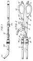
- a side view of a forceps device in accordance with the invention.
- the device is formed by joining elongated arms 10, 20 by pivot pin 30 thereby forming opposing coplanar jaw portions 40, 50 at one end of arms 10, 20.
- Each arm 10, 20 has at its other end an ovoid opening 60, 70 which, in conjunction with finger rests 62, 64, 72 and 74, form a hand grip for the forceps device.
- the jaw portions 40, 50 have a mechanism for securing removable tip portions.
- This mechanism consists of respective sleeves 80, 90.
- each of sleeves 80, 90 are spring loaded by springs 84, 94 between stops 42, 52 and retainer rings 44, 54 on hollow cylindrical extensions 45, 55 of jaw portions 40, 50 respectively.
- Detent balls 82, 92 are held in respective detent holes by sleeves 80, 90.
- a tip such as shown in Fig. 5 is removably secured by this mechanism by inserting the grooved end portion of the tip into hollow cylindrical extension 45 for example.
- physically identical portions of the tips shown in Figs. 1, 5, 10, 11 and 12 bear the same numerical designation.
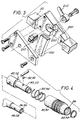
- FIG. 2 there is shown the ratchet mechanism of the forceps of the invention.
- a curved ratchet toothed member 100 is secured in a suitable channel of arm 10 by pin 110.
- Member 100 extends inwardly from arm 10 towards arm 20 and passes through pawl mechanism chamber 200 of arm 20.
- a pawl 210 controlled by pawl lever 215, is urged towards the teeth of member 100 by spring loaded ball 220.
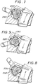
- Pawl lever 215 is used to position pawl 210 at one of the three detents; Fig.
- FIG. 9 shows detent 230 engaged by ball 220 to permit ratcheting open jaws 40, 50;
- Fig. 7 shows detent 240 engaged by ball 220 to disengage pawl 210 permitting jaws 40, 50 to open or close without ratcheting;
- Fig. 8 shows detent 250 engaged by ball 220 to permit ratcheting closed jaws 40, 50.
- the forceps of the invention are uniquely adapted to use with fixation systems utilizing plates screwed to the fractured bone and intended to span and compress the fracture.
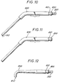
- the tip shown in Fig. 10 is a fixed tip 500 used in the forceps of the invention for compression and distraction in a plate and screw fixation system.
- This tip is a fixed position tip wherein square stud 300 fits into recesses 48, 58 of jaw portions 40, 50 and is thereby prevented from rotating about its axis.
- movable plates spanning a fracture can be adjusted by inserting tip ends 510 into holes in the plates and then ratcheting the jaws closed for a controlled compression or ratcheting the jaws open for distraction. Once the desired position and compression are achieved, the forceps will stay locked in position until the plates are permanently fixed.
- a tip of this type in one jaw of the forceps of the invention utilized with a fixed tip 500 in the other jaw permits axial rotation of the bone during manipulation prior to fixation.
- FIG. 1 there is shown another tip 700 with a specialized end piece 710 for use with plate fixation systems specifically designed with holes for accommodating such tip ends.
- a tenaculum tip 800 for use with the forceps of the invention.
- Two such tips secured in the jaw portion such that the points 810 are in opposition are used to grip and manipulate bones with the forceps of the invention.
Landscapes
- Health & Medical Sciences (AREA)
- Surgery (AREA)
- Life Sciences & Earth Sciences (AREA)
- Medical Informatics (AREA)
- Animal Behavior & Ethology (AREA)
- Engineering & Computer Science (AREA)
- Biomedical Technology (AREA)
- Heart & Thoracic Surgery (AREA)
- Orthopedic Medicine & Surgery (AREA)
- Molecular Biology (AREA)
- Nuclear Medicine, Radiotherapy & Molecular Imaging (AREA)
- General Health & Medical Sciences (AREA)
- Public Health (AREA)
- Veterinary Medicine (AREA)
- Ophthalmology & Optometry (AREA)
- Surgical Instruments (AREA)
- Orthopedics, Nursing, And Contraception (AREA)
- Prostheses (AREA)
Abstract
Description
- This invention relates broadly to clamping devices used in orthopedic surgery and more specifically to forceps used to manipulate and hold the bone for fixation of fractures.
- A number of efforts have been made in the art to provide bone-clamping and manipulating devices for use during orthopedic surgery. An exemplary clamping device using a hemostat clamp design is shown in U.S. Patent. No. 4,475,544 to Reis. It has also been known to adapt locking jaw pliers to the temporary clamping of a fractured bone under repair. A ratcheting arrangement for temporary clamping is shown in U.S. Patent No. 4,009,712 to Burstein, et al. A forceps according to the first part of claim 1 is known from DE-A-2 461 452.
- None of these prior art devices are entirely satisfactory for the wide range of manipulative procedures typically required in employing an internal screw and plate fixation system for the treatment of bone fractures. In addition, more than one such device is required to provide clamping, compression and distraction. It is an object of the present invention to provide all of these functions by utilizing easily changed tip portions on a forceps device having a reversible ratchet mechanism.
- The present invention is for a forceps having interchangeable tip elements and a reversible ratchet mechanism for controlling such tip elements, all as defined in Claim 1. Such a forceps is particularly useful in orthopedic procedures because a variety of tip elements can be used for compression and distraction of plate and screw fixation systems as well as gripping and manipulating the bone. The reversible ratchet mechanism permits controlled increments of force in either opening or closing the forceps jaws. In addition, the hand grip of the forceps of the invention has been shaped for comfort and ease of use.
- The forceps of the invention are particularly useful as a part of a modular system of internal fixation of bone fractures. Such a system utilizes a minimum number of plates that are employed interactively as to permit compressive, distractive and turning manipulation of the bone parts. The forceps of the invention make such manipulations possible by permitting use of a wide range easily of interchangeable tip configurations and providing incremental ratchet adjustment of either compressive or distractive forces.
- These and other advantages of the invention may best be understood by reference to the following detailed description of a preferred embodiment as shown in the accompanying drawings, wherein:
- Fig. 1 is a side view of the forceps of the invention showing an interchangeable tip element secured in the jaw portion.
- Fig. 2 is a view of the forceps of the invention showing the shape of the hand grip portions and the ratchet control lever.
- Fig. 3 is an exploded view of the ratchet control mechanism of the forceps of the invention.
- Fig. 4 is an exploded view of the interchangeable tip securing mechanism of the forceps of the invention.
- Fig. 5 is an illustration of the operation of interchangeable tip securing mechanism of the forceps of the invention.
- Fig. 6 is a side cut away view of the ratchet mechanism of the forceps of the invention.
- Fig. 7 is an illustration of the ratchet mechanism in the disengaged position.
- Fig. 8 is an illustration of the ratchet mechanism engaged to permit only ratchet controlled closing of the jaws of the forceps of the invention.
- Fig. 9 is an illustration of the ratchet mechanism engaged to permit only ratchet controlled opening of the jaws of the forceps of the invention.
- Fig. 10 is a fixed position interchangeable tip element for use with the forceps of the invention.
- Fig. 11 is a swiveling interchangeable tip element for use with the forceps of the invention.
- Fig. 12 is an interchangeable tenaculum tip element for use with the forceps of the invention.
- Referring to Fig. 1, there is shown a side view of a forceps device in accordance with the invention. As can be seen in Fig. 2, the device is formed by joining
elongated arms pivot pin 30 thereby forming opposingcoplanar jaw portions arms - Each
arm ovoid opening 60, 70 which, in conjunction with finger rests 62, 64, 72 and 74, form a hand grip for the forceps device. - The
jaw portions respective sleeves sleeves springs 84, 94 between stops 42, 52 andretainer rings 44, 54 on hollowcylindrical extensions 45, 55 ofjaw portions Detent balls 82, 92 are held in respective detent holes bysleeves cylindrical extension 45 for example. For ease of understanding physically identical portions of the tips shown in Figs. 1, 5, 10, 11 and 12 bear the same numerical designation. When the leadingshoulder 400 of the tip is stopped bydetent ball 82,sleeve 80 is manually urged againstspring 84 bringinggroove 86 into alignment withdetent ball 82 which moves outwardly intogroove 86 permitting the leadingshoulder 400 of the tip to move, to stop 46. When the tip is thus seated,groove 410 of the tip is aligned withdetent ball 82 and release ofsleeve 80 which is urged toward retainingring 44 byspring 84, locksdetent ball 82 intogroove 410 of the tip. - Referring now to Figs. 2, 3 and 6, there is shown the ratchet mechanism of the forceps of the invention. A curved
ratchet toothed member 100 is secured in a suitable channel ofarm 10 bypin 110.Member 100 extends inwardly fromarm 10 towardsarm 20 and passes throughpawl mechanism chamber 200 ofarm 20. Apawl 210, controlled bypawl lever 215, is urged towards the teeth ofmember 100 by spring loadedball 220. As shown in Figs. 7, 8 and 9 there are threedetents pawl 210 engageable byball 220. Pawllever 215 is used to positionpawl 210 at one of the three detents; Fig. 9 shows detent 230 engaged byball 220 to permit ratchetingopen jaws ball 220 to disengagepawl 210 permittingjaws ball 220 to permit ratcheting closedjaws - As was stated previously, the forceps of the invention are particularly useful in bone and joint surgical procedures therefore, a number of interchangeable tips for this purpose are shown in Figs. 1, 10, 11 and 12.
- In many typical orthopedic procedures, some form of fracture fixation is used. The forceps of the invention are uniquely adapted to use with fixation systems utilizing plates screwed to the fractured bone and intended to span and compress the fracture.
- The tip shown in Fig. 10 is a
fixed tip 500 used in the forceps of the invention for compression and distraction in a plate and screw fixation system. This tip is a fixed position tip whereinsquare stud 300 fits into recesses 48, 58 ofjaw portions - Referring now to Fig. 11, there is shown a
tip 600 identical to the 500 except that it does not have lockingstud 300 and can therefore rotate about an axis throughgroove 410. A tip of this type in one jaw of the forceps of the invention utilized with afixed tip 500 in the other jaw permits axial rotation of the bone during manipulation prior to fixation. - Referring now to Fig. 1, there is shown another
tip 700 with aspecialized end piece 710 for use with plate fixation systems specifically designed with holes for accommodating such tip ends. - Finally referring to Fig. 12, there is shown a
tenaculum tip 800 for use with the forceps of the invention. Two such tips secured in the jaw portion such that thepoints 810 are in opposition are used to grip and manipulate bones with the forceps of the invention.
Claims (3)
- A forceps device comprising:a) a first elongate arm (10) having a hand grip portion at a proximal end;b) a second elongate arm (20) having a hand grip portion at a proximal end;c) said first and second arms (10,20) being joined at a pivot point to form opposing co-planar jaw portions (40,50) at their distal ends;d) said jaw portions (40,50) being adapted to removably secure interchangeable tip portions;
characterised in thate) said first arm (10) has a ratchet toothed member (100) secured thereto intermediate said pivot point and said hand grip portion;f) said second arm (20) has a multiposition pawl mechanism positioned to engage said ratchet toothed member (100) such that in one position of said pawl (210), said arms (10,20) pivot to ratchet open said jaws (40,50), in a second position of said pawl (210), said arms pivot to ratchet closed said jaws (40,50) and in a third position, said pawl (210) is disengaged from said ratchet toothed member (100), whereby suitable tip portions are ratcheted to compress or distract a work piece. - The forceps device of claim 1 wherein said hand grip portions are shaped to form rounded ovoid openings (60,70) with the widest portion at the proximal end and further comprise curved finger rest portions (62,64,72,74) at both the distal and proximal ends of said openings (60,70).
- The forceps device of claim 1 wherein said jaw portions (40,50) removably secure said tip portions by way of a spring loaded sleeve (80,90), ball detent (82,92) and groove mechanism (86).
Applications Claiming Priority (3)
| Application Number | Priority Date | Filing Date | Title |
|---|---|---|---|
| US152455 | 1988-02-05 | ||
| US07/152,455 US4896661A (en) | 1988-02-05 | 1988-02-05 | Multi purpose orthopedic ratcheting forceps |
| PCT/US1989/000453 WO1989006939A1 (en) | 1988-02-05 | 1989-02-02 | Multi purpose orthopedic ratcheting forceps |
Publications (3)
| Publication Number | Publication Date |
|---|---|
| EP0393151A1 EP0393151A1 (en) | 1990-10-24 |
| EP0393151A4 EP0393151A4 (en) | 1991-01-02 |
| EP0393151B1 true EP0393151B1 (en) | 1994-05-18 |
Family
ID=22542996
Family Applications (1)
| Application Number | Title | Priority Date | Filing Date |
|---|---|---|---|
| EP89902587A Expired - Lifetime EP0393151B1 (en) | 1988-02-05 | 1989-02-02 | Multi purpose orthopedic ratcheting forceps |
Country Status (7)
| Country | Link |
|---|---|
| US (1) | US4896661A (en) |
| EP (1) | EP0393151B1 (en) |
| AT (1) | ATE105697T1 (en) |
| CA (1) | CA1302827C (en) |
| DE (1) | DE68915436T2 (en) |
| ES (1) | ES2017118A6 (en) |
| WO (1) | WO1989006939A1 (en) |
Cited By (1)
| Publication number | Priority date | Publication date | Assignee | Title |
|---|---|---|---|---|
| US7722625B2 (en) | 2004-06-30 | 2010-05-25 | Depuy Products, Inc. | Modular bone clamp instrument |
Families Citing this family (145)
| Publication number | Priority date | Publication date | Assignee | Title |
|---|---|---|---|---|
| US5176702A (en) * | 1991-04-04 | 1993-01-05 | Symbiosis Corporation | Ratchet locking mechanism for surgical instruments |
| US5201759A (en) * | 1991-04-29 | 1993-04-13 | Ferzli George S | Laparoscopic instrument |
| US5674244A (en) * | 1991-07-09 | 1997-10-07 | Synthes (U.S.A.) | Locking device on a pliers-shaped tool |
| US5476479A (en) * | 1991-09-26 | 1995-12-19 | United States Surgical Corporation | Handle for endoscopic surgical instruments and jaw structure |
| CA2075319C (en) * | 1991-09-26 | 1998-06-30 | Ernie Aranyi | Handle for surgical instruments |
| CA2075241A1 (en) * | 1991-10-03 | 1993-04-04 | Stephen W. Gerry | Handle for manipulating a laparoscopic tool |
| US5167662A (en) * | 1992-01-24 | 1992-12-01 | Zimmer, Inc. | Temporary clamp and inserter for a posterior midline spinal clamp |
| US5314424A (en) * | 1992-04-06 | 1994-05-24 | United States Surgical Corporation | Surgical instrument locking mechanism |
| US5297538A (en) * | 1992-04-10 | 1994-03-29 | Daniel Elie C | Surgical retractor/compressor |
| DE4235023A1 (en) * | 1992-07-22 | 1994-01-27 | Friedrichsfeld Ag | Gripping and / or cutting instrument for endoscopic purposes |
| CA2144211C (en) * | 1994-03-16 | 2005-05-24 | David T. Green | Surgical instruments useful for endoscopic spinal procedures |
| US5620458A (en) * | 1994-03-16 | 1997-04-15 | United States Surgical Corporation | Surgical instruments useful for endoscopic spinal procedures |
| DE19505761C1 (en) * | 1995-02-20 | 1996-04-25 | Klaas Dieter | Grip or forceps used when implanting intra=ocular lenses |
| US6309349B1 (en) * | 1996-04-10 | 2001-10-30 | Endoscopic Technologies, Inc. | Surgical retractor and stabilizing device and method for use |
| US5735857A (en) * | 1996-07-22 | 1998-04-07 | Bristol-Myers Squibb Co. | Prosthetic gripping instrument |
| US5785648A (en) * | 1996-10-09 | 1998-07-28 | David Min, M.D., Inc. | Speculum |
| ATE309752T1 (en) | 1997-02-11 | 2005-12-15 | Michelson Gary K | SYSTEM FOR ANTERIOR PLATING OF THE CERVICAL SPINE |
| JP4467647B2 (en) * | 1997-02-11 | 2010-05-26 | ウォーソー・オーソペディック・インコーポレーテッド | Bone plating system |
| US6042540A (en) * | 1997-08-18 | 2000-03-28 | Pacific Surgical Innovations, Inc. | Side-loading surgical retractor |
| US5993385A (en) * | 1997-08-18 | 1999-11-30 | Johnston; Terry | Self-aligning side-loading surgical retractor |
| US5938685A (en) * | 1997-09-05 | 1999-08-17 | Boston Scientific Corporation | Locking handle for surgical instruments |
| US5984865A (en) * | 1998-09-15 | 1999-11-16 | Thompson Surgical Instruments, Inc. | Surgical retractor having locking interchangeable blades |
| EP1117335B1 (en) * | 1998-10-02 | 2009-03-25 | Synthes GmbH | Spinal disc space distractor |
| US6347565B2 (en) | 1999-01-11 | 2002-02-19 | Hand Held Design Corporation | Multi-drive specialty tool |
| US6860179B2 (en) * | 1999-05-03 | 2005-03-01 | Irwin Industrial Tool Company | Clamp device |
| US6196969B1 (en) | 1999-05-21 | 2001-03-06 | Lab Engineering & Manufacturing, Inc. | Tissue retractor adapted for the attachment of an auxiliary element |
| US6293954B1 (en) * | 1999-06-21 | 2001-09-25 | Novare Surgical Systems, Inc. | Surgical clamp with replaceable clamp members |
| US6530929B1 (en) * | 1999-10-20 | 2003-03-11 | Sdgi Holdings, Inc. | Instruments for stabilization of bony structures |
| US6635072B1 (en) | 2000-07-20 | 2003-10-21 | Synthes | Safety ratchet mechanism |
| US6336386B1 (en) * | 2000-07-21 | 2002-01-08 | Yung Jen Lee | Plier device having an adjustable opening |
| US6589241B1 (en) * | 2000-10-12 | 2003-07-08 | Zimmer, Inc. | Bone clamp |
| US6716218B2 (en) * | 2001-02-28 | 2004-04-06 | Hol-Med Corporation | Instrument for bone distraction and compression having ratcheting tips |
| US7862587B2 (en) | 2004-02-27 | 2011-01-04 | Jackson Roger P | Dynamic stabilization assemblies, tool set and method |
| US6860850B2 (en) * | 2001-10-05 | 2005-03-01 | Boss Instruments Ltd. | Retractor blade connector head |
| AUPS198502A0 (en) * | 2002-04-26 | 2002-06-06 | Research Surgical Pty Ltd | Retractor |
| DE60318211T2 (en) | 2002-05-21 | 2008-12-04 | Warsaw Orthopedic, Inc., Warsaw | DEVICE FOR THE DISTRACTION OF BONE SEGMENTS |
| US7004947B2 (en) * | 2002-06-24 | 2006-02-28 | Endius Incorporated | Surgical instrument for moving vertebrae |
| US6711789B2 (en) * | 2002-08-14 | 2004-03-30 | Great Neck Saw Manufacturers, Inc. | Clamp |
| EP3222231A1 (en) | 2002-10-30 | 2017-09-27 | Zimmer Spine, Inc. | Spinal stabilization system insertion |
| US9539012B2 (en) | 2002-10-30 | 2017-01-10 | Zimmer Spine, Inc. | Spinal stabilization systems with quick-connect sleeve assemblies for use in surgical procedures |
| EP1415600A1 (en) * | 2002-11-04 | 2004-05-06 | Stryker Trauma - Selzach AG | Orthopaedic ratcheting forceps |
| US7887539B2 (en) | 2003-01-24 | 2011-02-15 | Depuy Spine, Inc. | Spinal rod approximators |
| US7988698B2 (en) * | 2003-01-28 | 2011-08-02 | Depuy Spine, Inc. | Spinal rod approximator |
| US20040267275A1 (en) * | 2003-06-26 | 2004-12-30 | Cournoyer John R. | Spinal implant holder and rod reduction systems and methods |
| US7635365B2 (en) * | 2003-08-28 | 2009-12-22 | Ellis Thomas J | Bone plates |
| US7455685B2 (en) * | 2003-09-29 | 2008-11-25 | Warsaw Orthopedic, Inc. | Instruments and methods for securing a connecting element along a bony segment |
| US7655009B2 (en) * | 2003-12-01 | 2010-02-02 | Smith & Nephew, Inc. | Humeral nail |
| US11419642B2 (en) | 2003-12-16 | 2022-08-23 | Medos International Sarl | Percutaneous access devices and bone anchor assemblies |
| US7666188B2 (en) * | 2003-12-16 | 2010-02-23 | Depuy Spine, Inc. | Methods and devices for spinal fixation element placement |
| US7179261B2 (en) | 2003-12-16 | 2007-02-20 | Depuy Spine, Inc. | Percutaneous access devices and bone anchor assemblies |
| US7842044B2 (en) * | 2003-12-17 | 2010-11-30 | Depuy Spine, Inc. | Instruments and methods for bone anchor engagement and spinal rod reduction |
| EP1694226B1 (en) * | 2003-12-17 | 2009-09-02 | DePuy Spine, Inc. | Instruments and methods for bone anchor engagement and spinal rod reduction |
| US7491168B2 (en) | 2003-12-18 | 2009-02-17 | Depuy Spine, Inc. | Surgical retractor systems and illuminated cannulae |
| US7468069B2 (en) | 2004-02-10 | 2008-12-23 | Atlas Spine, Inc. | Static anterior cervical plate |
| US7160300B2 (en) | 2004-02-27 | 2007-01-09 | Jackson Roger P | Orthopedic implant rod reduction tool set and method |
| WO2005092218A1 (en) | 2004-02-27 | 2005-10-06 | Jackson Roger P | Orthopedic implant rod reduction tool set and method |
| US7114279B2 (en) * | 2004-03-19 | 2006-10-03 | Streamworks, Llc | Fishhook barb crimping tool |
| US7288095B2 (en) | 2004-08-12 | 2007-10-30 | Atlas Spine, Inc. | Bone plate with screw lock |
| US7465306B2 (en) * | 2004-08-13 | 2008-12-16 | Warsaw Orthopedic, Inc. | System and method for positioning a connecting member adjacent the spinal column in minimally invasive procedures |
| US7727256B2 (en) * | 2004-09-24 | 2010-06-01 | Arthrex, Inc. | Grasper assembly |
| US20080154277A1 (en) * | 2004-10-26 | 2008-06-26 | Scott Machalk | Tool apparatus for locking a spinal rod in an anchoring device therefor |
| US20060089651A1 (en) * | 2004-10-26 | 2006-04-27 | Trudeau Jeffrey L | Apparatus and method for anchoring a surgical rod |
| WO2006069089A2 (en) * | 2004-12-21 | 2006-06-29 | Packaging Service Corporation Of Kentucky | Cervical plate system |
| US7438715B2 (en) * | 2005-01-06 | 2008-10-21 | Spinal Llc | Spinal implant kit |
| US7322984B2 (en) | 2005-01-06 | 2008-01-29 | Spinal, Llc | Spinal plate with internal screw locks |
| US7842045B2 (en) | 2005-01-19 | 2010-11-30 | Applied Medical Resources Corporation | Single fire vascular clip applier with disposable jaw |
| US7410488B2 (en) | 2005-02-18 | 2008-08-12 | Smith & Nephew, Inc. | Hindfoot nail |
| US7951172B2 (en) | 2005-03-04 | 2011-05-31 | Depuy Spine Sarl | Constrained motion bone screw assembly |
| US7951175B2 (en) | 2005-03-04 | 2011-05-31 | Depuy Spine, Inc. | Instruments and methods for manipulating a vertebra |
| US7491208B2 (en) | 2005-04-28 | 2009-02-17 | Warsaw Orthopedic, Inc. | Instrument and method for guiding surgical implants and instruments during surgery |
| US20060293692A1 (en) | 2005-06-02 | 2006-12-28 | Whipple Dale E | Instruments and methods for manipulating a spinal fixation element |
| US7695475B2 (en) * | 2005-08-26 | 2010-04-13 | Warsaw Orthopedic, Inc. | Instruments for minimally invasive stabilization of bony structures |
| US7415912B2 (en) * | 2005-09-02 | 2008-08-26 | Maine Land Research & Development, Inc. | Locking clamp device |
| US7373862B2 (en) * | 2005-09-02 | 2008-05-20 | Maine Land Research & Development, Inc. | Clamp device |
| US7981031B2 (en) | 2006-01-04 | 2011-07-19 | Depuy Spine, Inc. | Surgical access devices and methods of minimally invasive surgery |
| US7758501B2 (en) * | 2006-01-04 | 2010-07-20 | Depuy Spine, Inc. | Surgical reactors and methods of minimally invasive surgery |
| US7955257B2 (en) * | 2006-01-05 | 2011-06-07 | Depuy Spine, Inc. | Non-rigid surgical retractor |
| US8840621B2 (en) | 2006-11-03 | 2014-09-23 | Innovative Spine, Inc. | Spinal access systems and methods |
| BRPI0721117A2 (en) * | 2006-12-15 | 2014-06-03 | Synthes Gmbh | OSTEOTOMY GUIDE TO CUT A BONE, AND METHOD |
| US20080228233A1 (en) * | 2007-02-12 | 2008-09-18 | Jeffrey Hoffman | Instrument for manipulating spinal implant system |
| US20080195155A1 (en) * | 2007-02-12 | 2008-08-14 | Jeffrey Hoffman | Locking instrument for implantable fixation device |
| US8308774B2 (en) * | 2007-02-14 | 2012-11-13 | Pioneer Surgical Technology, Inc. | Spinal rod reducer and cap insertion apparatus |
| US20080249531A1 (en) * | 2007-02-27 | 2008-10-09 | Warsaw Orthopedic, Inc. | Instruments and methods for minimally invasive insertion of dynamic implants |
| US8172847B2 (en) * | 2007-03-29 | 2012-05-08 | Depuy Spine, Inc. | In-line rod reduction device and methods |
| US7887541B2 (en) * | 2007-07-26 | 2011-02-15 | Depuy Spine, Inc. | Spinal rod reduction instruments and methods for use |
| US8790348B2 (en) | 2007-09-28 | 2014-07-29 | Depuy Spine, Inc. | Dual pivot instrument for reduction of a fixation element and method of use |
| US8235997B2 (en) * | 2008-01-29 | 2012-08-07 | Pioneer Surgical Technology, Inc. | Rod locking instrument |
| US8608746B2 (en) | 2008-03-10 | 2013-12-17 | DePuy Synthes Products, LLC | Derotation instrument with reduction functionality |
| US8709015B2 (en) | 2008-03-10 | 2014-04-29 | DePuy Synthes Products, LLC | Bilateral vertebral body derotation system |
| US7669505B2 (en) * | 2008-05-27 | 2010-03-02 | Black & Decker Inc. | Pin lock pliers |
| US20090306672A1 (en) * | 2008-06-05 | 2009-12-10 | Alphatec Spine,Inc. | Alif inserter/distractor |
| US10973556B2 (en) | 2008-06-17 | 2021-04-13 | DePuy Synthes Products, Inc. | Adjustable implant assembly |
| US20100018365A1 (en) * | 2008-07-24 | 2010-01-28 | Maine Land Research & Development , Inc. | Removable clamping member |
| US8211012B2 (en) * | 2008-09-30 | 2012-07-03 | Aesculap Implant Systems, Llc | Tissue retractor system |
| US12285197B2 (en) | 2008-10-10 | 2025-04-29 | Acumed Llc | Bone fixation system with opposed mounting portions |
| US9237910B2 (en) | 2012-01-26 | 2016-01-19 | Acute Innovations Llc | Clip for rib stabilization |
| US8919228B1 (en) | 2009-03-04 | 2014-12-30 | Hua Gao | Precision ratcheting mechanism for gripping device |
| SE533864C2 (en) * | 2009-04-30 | 2011-02-15 | Pressmaster Ab | ratchet mechanism |
| US8206394B2 (en) * | 2009-05-13 | 2012-06-26 | Depuy Spine, Inc. | Torque limited instrument for manipulating a spinal rod relative to a bone anchor |
| US8568417B2 (en) | 2009-12-18 | 2013-10-29 | Charles River Engineering Solutions And Technologies, Llc | Articulating tool and methods of using |
| WO2011084275A1 (en) * | 2010-01-05 | 2011-07-14 | The Johns Hopkins University | Compression-distraction spinal fixation system |
| US8968367B2 (en) * | 2010-01-05 | 2015-03-03 | The Johns Hopkins University | Compression-distraction spinal fixation system and kit |
| US8545505B2 (en) | 2010-01-15 | 2013-10-01 | Pioneer Surgical Technology, Inc. | Low friction rod persuader |
| US8900240B2 (en) * | 2010-02-12 | 2014-12-02 | Pioneer Surgical Technology, Inc. | Spinal rod and screw securing apparatus and method |
| US20120042709A1 (en) * | 2010-08-23 | 2012-02-23 | Conbraco Industries, Inc. | Pex clamp fastening tool |
| US8747410B2 (en) * | 2010-10-26 | 2014-06-10 | Zimmer, Inc. | Patellar resection instrument with variable depth guide |
| US9907582B1 (en) | 2011-04-25 | 2018-03-06 | Nuvasive, Inc. | Minimally invasive spinal fixation system and related methods |
| US9636169B2 (en) | 2011-09-19 | 2017-05-02 | Covidien Lp | Electrosurgical instrument |
| JP6240076B2 (en) | 2011-09-30 | 2017-11-29 | アキュート・イノヴェーションズ・エルエルシー | Bone fixation system with opposing mounting parts |
| EP2689737B1 (en) | 2012-07-25 | 2016-04-13 | Stryker European Holdings I, LLC | Surgical reduction clamp |
| US8979866B2 (en) * | 2012-07-30 | 2015-03-17 | Wright Medical Technology, Inc. | Surgical tool |
| EP3427682B1 (en) | 2013-03-15 | 2020-09-23 | Gyrus ACMI, Inc. (D.B.A. Olympus Surgical Technologies America) | Combination electrosurgical device |
| CN108078625B (en) | 2013-03-15 | 2020-11-17 | 捷锐士阿希迈公司(以奥林巴斯美国外科技术名义) | Offset surgical forceps |
| WO2014143472A1 (en) | 2013-03-15 | 2014-09-18 | GYRUS ACMI, INC. (d/b/a OLYMPUS SURGICAL TECHNOLOGIES AMERICA) | Electrosurgical instrument |
| EP2974682B1 (en) | 2013-03-15 | 2017-08-30 | Gyrus ACMI, Inc. | Combination electrosurgical device |
| CN105025833B (en) | 2013-03-15 | 2017-11-21 | 捷锐士阿希迈公司(以奥林巴斯美国外科技术名义) | Combined Electrosurgical Equipment |
| US10058311B1 (en) | 2013-10-09 | 2018-08-28 | Rogelio A. Insignares | Ergonomic multi-functional handle for use with a medical instrument |
| US9717485B1 (en) | 2013-10-09 | 2017-08-01 | Daniel Glenn Doerr | Ergonomic multi-functional handle for use with a medical instrument |
| USD738174S1 (en) * | 2014-04-24 | 2015-09-08 | A & E Incorporated | Locking pliers |
| USD742194S1 (en) * | 2014-04-24 | 2015-11-03 | A & E Incorporated | Locking pliers |
| CN106659534B (en) | 2014-08-20 | 2020-03-17 | 捷锐士阿希迈公司(以奥林巴斯美国外科技术名义) | Reconfigurable electrosurgical device |
| US10201891B2 (en) * | 2014-10-17 | 2019-02-12 | Matthew E. Williams | Alignment and adjustment clamp |
| US9550277B1 (en) * | 2014-10-17 | 2017-01-24 | Matthew E. Williams | Alignment and adjustment clamp |
| US9848863B2 (en) | 2015-02-25 | 2017-12-26 | Globus Medical, Inc | Surgical retractor systems and methods |
| EP3273892B1 (en) | 2015-03-23 | 2019-10-16 | Gyrus ACMI, Inc. (D.B.A. Olympus Surgical Technologies America) | Medical forceps with vessel transection capability |
| US9700293B2 (en) | 2015-08-18 | 2017-07-11 | Globus Medical, Inc. | Devices and systems for surgical retraction |
| US10194960B1 (en) | 2015-12-03 | 2019-02-05 | Nuvasive, Inc. | Spinal compression instrument and related methods |
| TWI618551B (en) * | 2016-03-28 | 2018-03-21 | 英濟股份有限公司 | Expander |
| US10314599B2 (en) | 2016-03-31 | 2019-06-11 | Howmedica Osteonics Corp. | Navigated patella clamp |
| US10441337B2 (en) | 2016-04-15 | 2019-10-15 | Stryker European Holdings I, Llc | Distraction and compression in one plier |
| US10588696B2 (en) | 2016-08-03 | 2020-03-17 | Mako Surgical Corp. | Patella implant planning |
| US11298801B2 (en) | 2017-11-02 | 2022-04-12 | Gyrus Acmi, Inc. | Bias device for biasing a gripping device including a central body and shuttles on the working arms |
| US10667834B2 (en) | 2017-11-02 | 2020-06-02 | Gyrus Acmi, Inc. | Bias device for biasing a gripping device with a shuttle on a central body |
| US11383373B2 (en) | 2017-11-02 | 2022-07-12 | Gyms Acmi, Inc. | Bias device for biasing a gripping device by biasing working arms apart |
| US10966762B2 (en) | 2017-12-15 | 2021-04-06 | Medos International Sarl | Unilateral implant holders and related methods |
| US11071570B2 (en) | 2018-03-02 | 2021-07-27 | Globus Medical, Inc. | Distal tibial plating system |
| US11224468B2 (en) | 2018-03-02 | 2022-01-18 | Globus Medical, Inc. | Distal tibial plating system |
| USD1004774S1 (en) | 2019-03-21 | 2023-11-14 | Medos International Sarl | Kerrison rod reducer |
| US11291482B2 (en) | 2019-03-21 | 2022-04-05 | Medos International Sarl | Rod reducers and related methods |
| US11291481B2 (en) | 2019-03-21 | 2022-04-05 | Medos International Sarl | Rod reducers and related methods |
| WO2022096752A1 (en) | 2020-11-09 | 2022-05-12 | Medos International Sarl | Biplanar forceps reducers |
| US12274431B2 (en) | 2021-08-12 | 2025-04-15 | Wright Medical Technology, Inc. | Surgical distractor and methods of manufacture and use |
| GB2611037B (en) * | 2021-09-22 | 2023-12-27 | Toit Fishing Ltd | Split ring pliers |
| AU2022390426A1 (en) | 2021-11-19 | 2024-07-04 | Medos International Sarl | Reducer locking mechanisms |
| US12214476B2 (en) * | 2022-03-10 | 2025-02-04 | A & E Incorporated | Switchable pliers and method for use |
Family Cites Families (7)
| Publication number | Priority date | Publication date | Assignee | Title |
|---|---|---|---|---|
| FR401732A (en) * | 1909-04-05 | 1909-09-13 | Maurice Pollosson | Forceps for closing the uterus by pinching the cervix |
| US2427128A (en) * | 1946-01-28 | 1947-09-09 | Zimmer Mfg Company | Surgical bone clamp |
| US2669992A (en) * | 1952-02-04 | 1954-02-23 | Pedro D Curutchet | Grip for lever pivoted instruments |
| US3470872A (en) * | 1966-11-25 | 1969-10-07 | Herman R Grieshaber | Pivoted retractor with shielded spacer teeth |
| DE1628079A1 (en) * | 1967-01-31 | 1971-06-09 | Licentia Gmbh | Gearbox suitable for screwing or drilling |
| DE2461452A1 (en) * | 1974-12-24 | 1976-07-08 | Siegfried Khan | Adaptable combination pliers with clamping pivot - has pivot with sleeve and pin for ready separation of plier arms |
| US4274311A (en) * | 1979-07-23 | 1981-06-23 | Emil Ebert | Ratchet wrench handle |
-
1988
- 1988-02-05 US US07/152,455 patent/US4896661A/en not_active Expired - Lifetime
-
1989
- 1989-02-01 CA CA000589799A patent/CA1302827C/en not_active Expired - Lifetime
- 1989-02-02 DE DE68915436T patent/DE68915436T2/en not_active Expired - Lifetime
- 1989-02-02 EP EP89902587A patent/EP0393151B1/en not_active Expired - Lifetime
- 1989-02-02 WO PCT/US1989/000453 patent/WO1989006939A1/en not_active Ceased
- 1989-02-02 AT AT89902587T patent/ATE105697T1/en not_active IP Right Cessation
- 1989-02-03 ES ES8900381A patent/ES2017118A6/en not_active Expired - Fee Related
Cited By (1)
| Publication number | Priority date | Publication date | Assignee | Title |
|---|---|---|---|---|
| US7722625B2 (en) | 2004-06-30 | 2010-05-25 | Depuy Products, Inc. | Modular bone clamp instrument |
Also Published As
| Publication number | Publication date |
|---|---|
| CA1302827C (en) | 1992-06-09 |
| ES2017118A6 (en) | 1991-01-01 |
| DE68915436T2 (en) | 1994-09-01 |
| EP0393151A4 (en) | 1991-01-02 |
| US4896661A (en) | 1990-01-30 |
| ATE105697T1 (en) | 1994-06-15 |
| WO1989006939A1 (en) | 1989-08-10 |
| DE68915436D1 (en) | 1994-06-23 |
| EP0393151A1 (en) | 1990-10-24 |
Similar Documents
| Publication | Publication Date | Title |
|---|---|---|
| US4896661A (en) | Multi purpose orthopedic ratcheting forceps | |
| US9339319B2 (en) | Surgical reduction clamp | |
| USRE43526E1 (en) | Rod introduction apparatus | |
| US5122150A (en) | Neurosurgical clip applier | |
| US8657857B2 (en) | Bone fixation device | |
| CA2452759C (en) | Surgical rod reducer instruments and methods | |
| US7618444B2 (en) | Surgical instrument for moving a vertebra | |
| AU767513B2 (en) | Device for distracting or compressing bones or bone fragments | |
| US9439679B2 (en) | Bone fixation system | |
| US20060111730A1 (en) | Deformity reduction instrument and method | |
| US6605088B1 (en) | Bone setting apparatus and method | |
| US8617165B2 (en) | Rod reducing instrument and methods of use thereof | |
| US7625391B2 (en) | Orthopaedic ratcheting forceps | |
| US20060089651A1 (en) | Apparatus and method for anchoring a surgical rod | |
| JP6764951B2 (en) | Devices and kits for positioning implants for interbody fusion | |
| WO2007092876A2 (en) | Methods and instruments for spinal derotation | |
| CN108697443B (en) | Medical instrument and medical instrument | |
| US10441337B2 (en) | Distraction and compression in one plier | |
| US10729477B2 (en) | Clip-on reducer | |
| GB2455182A (en) | Clamp for use in orthopaedic surgery | |
| US12599410B2 (en) | Multi-clamp apparatus for external bone fixator | |
| US4995876A (en) | Neurosurgical clip applier | |
| EP4238517A1 (en) | Bone reattachment system | |
| MXPA01002316A (en) | Repositioning instrument for the fixation of bone fractures | |
| HK1009735B (en) | Method and apparatus for external fixation of small bones |
Legal Events
| Date | Code | Title | Description |
|---|---|---|---|
| PUAI | Public reference made under article 153(3) epc to a published international application that has entered the european phase |
Free format text: ORIGINAL CODE: 0009012 |
|
| 17P | Request for examination filed |
Effective date: 19900228 |
|
| AK | Designated contracting states |
Kind code of ref document: A1 Designated state(s): AT BE CH DE FR GB IT LI LU NL SE |
|
| A4 | Supplementary search report drawn up and despatched |
Effective date: 19901112 |
|
| AK | Designated contracting states |
Kind code of ref document: A4 Designated state(s): AT BE CH DE FR GB IT LI LU NL SE |
|
| 17Q | First examination report despatched |
Effective date: 19930428 |
|
| RAP1 | Party data changed (applicant data changed or rights of an application transferred) |
Owner name: HOWMEDICA INC. |
|
| ITTA | It: last paid annual fee | ||
| GRAA | (expected) grant |
Free format text: ORIGINAL CODE: 0009210 |
|
| AK | Designated contracting states |
Kind code of ref document: B1 Designated state(s): AT BE CH DE FR GB IT LI LU NL SE |
|
| REF | Corresponds to: |
Ref document number: 105697 Country of ref document: AT Date of ref document: 19940615 Kind code of ref document: T |
|
| REF | Corresponds to: |
Ref document number: 68915436 Country of ref document: DE Date of ref document: 19940623 |
|
| ET | Fr: translation filed | ||
| ITF | It: translation for a ep patent filed | ||
| EAL | Se: european patent in force in sweden |
Ref document number: 89902587.8 |
|
| PLBE | No opposition filed within time limit |
Free format text: ORIGINAL CODE: 0009261 |
|
| STAA | Information on the status of an ep patent application or granted ep patent |
Free format text: STATUS: NO OPPOSITION FILED WITHIN TIME LIMIT |
|
| 26N | No opposition filed | ||
| PGFP | Annual fee paid to national office [announced via postgrant information from national office to epo] |
Ref country code: SE Payment date: 19981218 Year of fee payment: 11 |
|
| PGFP | Annual fee paid to national office [announced via postgrant information from national office to epo] |
Ref country code: NL Payment date: 19981222 Year of fee payment: 11 |
|
| PGFP | Annual fee paid to national office [announced via postgrant information from national office to epo] |
Ref country code: AT Payment date: 19990112 Year of fee payment: 11 |
|
| PGFP | Annual fee paid to national office [announced via postgrant information from national office to epo] |
Ref country code: BE Payment date: 19990118 Year of fee payment: 11 |
|
| PGFP | Annual fee paid to national office [announced via postgrant information from national office to epo] |
Ref country code: CH Payment date: 19990216 Year of fee payment: 11 |
|
| PGFP | Annual fee paid to national office [announced via postgrant information from national office to epo] |
Ref country code: LU Payment date: 19990218 Year of fee payment: 11 |
|
| REG | Reference to a national code |
Ref country code: CH Ref legal event code: NV Representative=s name: E. BLUM & CO. PATENTANWAELTE |
|
| PG25 | Lapsed in a contracting state [announced via postgrant information from national office to epo] |
Ref country code: LU Free format text: LAPSE BECAUSE OF NON-PAYMENT OF DUE FEES Effective date: 20000202 Ref country code: AT Free format text: LAPSE BECAUSE OF NON-PAYMENT OF DUE FEES Effective date: 20000202 |
|
| PG25 | Lapsed in a contracting state [announced via postgrant information from national office to epo] |
Ref country code: SE Free format text: LAPSE BECAUSE OF NON-PAYMENT OF DUE FEES Effective date: 20000203 |
|
| PG25 | Lapsed in a contracting state [announced via postgrant information from national office to epo] |
Ref country code: BE Free format text: LAPSE BECAUSE OF NON-PAYMENT OF DUE FEES Effective date: 20000228 |
|
| PG25 | Lapsed in a contracting state [announced via postgrant information from national office to epo] |
Ref country code: LI Free format text: LAPSE BECAUSE OF NON-PAYMENT OF DUE FEES Effective date: 20000229 Ref country code: CH Free format text: LAPSE BECAUSE OF NON-PAYMENT OF DUE FEES Effective date: 20000229 |
|
| REG | Reference to a national code |
Ref country code: GB Ref legal event code: 732E |
|
| BERE | Be: lapsed |
Owner name: HOWMEDICA INC. Effective date: 20000228 |
|
| PG25 | Lapsed in a contracting state [announced via postgrant information from national office to epo] |
Ref country code: NL Free format text: LAPSE BECAUSE OF NON-PAYMENT OF DUE FEES Effective date: 20000901 |
|
| EUG | Se: european patent has lapsed |
Ref document number: 89902587.8 |
|
| REG | Reference to a national code |
Ref country code: CH Ref legal event code: PL |
|
| NLV4 | Nl: lapsed or anulled due to non-payment of the annual fee |
Effective date: 20000901 |
|
| REG | Reference to a national code |
Ref country code: GB Ref legal event code: IF02 |
|
| REG | Reference to a national code |
Ref country code: GB Ref legal event code: 732E |
|
| PG25 | Lapsed in a contracting state [announced via postgrant information from national office to epo] |
Ref country code: IT Free format text: LAPSE BECAUSE OF NON-PAYMENT OF DUE FEES Effective date: 20050202 |
|
| REG | Reference to a national code |
Ref country code: FR Ref legal event code: TP |
|
| PGFP | Annual fee paid to national office [announced via postgrant information from national office to epo] |
Ref country code: GB Payment date: 20080108 Year of fee payment: 20 Ref country code: DE Payment date: 20080229 Year of fee payment: 20 |
|
| PGFP | Annual fee paid to national office [announced via postgrant information from national office to epo] |
Ref country code: FR Payment date: 20080212 Year of fee payment: 20 |
|
| REG | Reference to a national code |
Ref country code: GB Ref legal event code: PE20 Expiry date: 20090201 |
|
| PG25 | Lapsed in a contracting state [announced via postgrant information from national office to epo] |
Ref country code: GB Free format text: LAPSE BECAUSE OF EXPIRATION OF PROTECTION Effective date: 20090201 |