EP0392991B1 - A mechanism for the automatic release of control bars in a nuclear reactor - Google Patents
A mechanism for the automatic release of control bars in a nuclear reactor Download PDFInfo
- Publication number
- EP0392991B1 EP0392991B1 EP90830150A EP90830150A EP0392991B1 EP 0392991 B1 EP0392991 B1 EP 0392991B1 EP 90830150 A EP90830150 A EP 90830150A EP 90830150 A EP90830150 A EP 90830150A EP 0392991 B1 EP0392991 B1 EP 0392991B1
- Authority
- EP
- European Patent Office
- Prior art keywords
- thermal sensor
- bar
- reactor
- bars
- hook
- Prior art date
- Legal status (The legal status is an assumption and is not a legal conclusion. Google has not performed a legal analysis and makes no representation as to the accuracy of the status listed.)
- Expired - Lifetime
Links
- 230000007246 mechanism Effects 0.000 title claims description 18
- 239000000446 fuel Substances 0.000 claims description 14
- 230000005540 biological transmission Effects 0.000 claims description 9
- 239000000463 material Substances 0.000 claims description 8
- 239000012809 cooling fluid Substances 0.000 claims description 7
- 230000005484 gravity Effects 0.000 claims description 7
- 230000008859 change Effects 0.000 claims description 5
- 239000003758 nuclear fuel Substances 0.000 claims description 3
- 238000004519 manufacturing process Methods 0.000 claims description 2
- 239000007787 solid Substances 0.000 claims 1
- 238000006243 chemical reaction Methods 0.000 description 4
- 230000009471 action Effects 0.000 description 2
- 230000000694 effects Effects 0.000 description 2
- 239000002184 metal Substances 0.000 description 2
- 229910052751 metal Inorganic materials 0.000 description 2
- 230000004044 response Effects 0.000 description 2
- XLYOFNOQVPJJNP-UHFFFAOYSA-N water Substances O XLYOFNOQVPJJNP-UHFFFAOYSA-N 0.000 description 2
- 230000008901 benefit Effects 0.000 description 1
- 239000000110 cooling liquid Substances 0.000 description 1
- 230000007547 defect Effects 0.000 description 1
- 230000008030 elimination Effects 0.000 description 1
- 238000003379 elimination reaction Methods 0.000 description 1
- 230000007717 exclusion Effects 0.000 description 1
- 239000012530 fluid Substances 0.000 description 1
- 230000009347 mechanical transmission Effects 0.000 description 1
- 150000002739 metals Chemical group 0.000 description 1
- 230000004048 modification Effects 0.000 description 1
- 238000012986 modification Methods 0.000 description 1
- 230000006903 response to temperature Effects 0.000 description 1
- 239000000126 substance Substances 0.000 description 1
Images


Classifications
-
- G—PHYSICS
- G21—NUCLEAR PHYSICS; NUCLEAR ENGINEERING
- G21C—NUCLEAR REACTORS
- G21C9/00—Emergency protection arrangements structurally associated with the reactor, e.g. safety valves provided with pressure equalisation devices
- G21C9/02—Means for effecting very rapid reduction of the reactivity factor under fault conditions, e.g. reactor fuse; Control elements having arrangements activated in an emergency
-
- Y—GENERAL TAGGING OF NEW TECHNOLOGICAL DEVELOPMENTS; GENERAL TAGGING OF CROSS-SECTIONAL TECHNOLOGIES SPANNING OVER SEVERAL SECTIONS OF THE IPC; TECHNICAL SUBJECTS COVERED BY FORMER USPC CROSS-REFERENCE ART COLLECTIONS [XRACs] AND DIGESTS
- Y02—TECHNOLOGIES OR APPLICATIONS FOR MITIGATION OR ADAPTATION AGAINST CLIMATE CHANGE
- Y02E—REDUCTION OF GREENHOUSE GAS [GHG] EMISSIONS, RELATED TO ENERGY GENERATION, TRANSMISSION OR DISTRIBUTION
- Y02E30/00—Energy generation of nuclear origin
- Y02E30/30—Nuclear fission reactors
Definitions
- control bars are released following a request of shutdown of the chain reaction, mostly by means of electromechanical servomechanisms servoed to control chains that include a complex instrumentation; this is also made necessary by the plurality of conditions of the plant and the physical parameters that may require such shutdown.
- the thermal sensor generally shown in 1 of the mechanism according to the present invention realized as a bimetal pair of the kind that entails the development of an axial force as a function of temperature.
- the thermal sensor 1 comprises a first bar 2 the upper end of which is fastened to a rigid structure S while the opposed lower end is fastened to the lower end of a second bar 3, spaced from and parallel to the first one, the upper end of the second bar being free.
- the first and the second bars 2, 3 are realized with materials having different coefficient of thermal expansion, and in particular, the coefficient of thermal expansion of the second bar 3 is substantially greater than that of the first bar 2, and as a consequence, following a variation of the temperature, different elongation will occur in the two abovesaid bars, and more precisely, the elongation of the second bar 3 will be greater than that of the first bar 2, as it can be appreciated from figure 2.
- the relative elongation of the second bar 2 that intrinsecally can not be prevented or suppressed, will produce an axial force which is utilized, according to the present invention for performing automatically, in the event of an increase of the temperature of the cooling fluid, the release of the control bars in the way that will be better explained hereinafter.
- the thermal sensor already shown schematically and disclosed with reference to figures 1 and 2, and constituted in this case by two bars 14 and 15 having a cylindrical symmetry, and concentrical, of which the one shown in 15 is realized with a material having a coefficient of thermal expansion greater than that of the material with which the bar 14 is constituted, rigidly coupled in correspondence with their lower ends by means of a connection member 16.
- the upper ends of the bars 14 and 15 are fastened to the lower ends of respective transmission rods 17 and 18, made of a material either responsive or not to thermal variations, of which the first one has the upper end locked in 19 to the rigid structure 12, fastened, as above said, to the upper plate 4 of the reactor, while the second one extends up to near the actuator 11 at a distance D from this latter, constituting the play or dead space existing when the thermal sensor 13 is in the non-operative condition.
- the distance D may be adjusted as a function of the temperature for which the release is sought.
- the transmission rods 17 and 18 may be omitted, and in this case the bars 14 and 15 of the sensor 13 will extend respectively up to the above mentioned respective positions of the upper ends of the transmission rods 17 and 18.
- Said system for holding the bundle of bars 7 in the suspended condition comprises two hooks 10, symmetrical with respect to the axis of the bundle of control bars 7, of which hooks only one is shown in the figure, in register with respective opposite sides of the support plate 8 of the bundle of control bars 7, suitable for engagement with respective brackets 9 protruding above from the plate 8, for supporting said control bars in said extracted position.
- Each of said hooks 10 has the end opposite to the one in engagement with the respective bracket 9 of the plate 8, pivoted in 20 onto the rigid structure 12 which is part of the reactor and in an intermediate position is rotatably connected by means of the pin 21 to an end of a swinging lever 22, that constitutes in this case said actuator, the opposite end of which is connected rotatably by means of the pin 23 to the upper end of the tubular transmission rod 18 that, being concentrical as above said externally with respect to the rod 17, has the lower end fastened to the upper end of the bar 15 having a coefficient of thermal expansion greater than that of the bar 14 of the thermal sensor 13.
- the thermal sensor 13 may have the internal bar 14 realized with a material having a coefficient of thermal expansion greater than that of the material of the external bar 15, in such case the operation of the actuator 11, when the temperature increses above the predetermined limit, will not occur following the lifting of the bar 18 fastended to the bar 15, but following the pulling downwards of the same following the elongation in said direction of the bar 14, the lower end of which is fastened, as above said, to the corresponding end of the bar 15.
- the structure of the actuator 11 will have obviously, to be modified and, in particular, in the example of figure 4, the linkage referred to, the members 10, 18, 20, 21, 22, 23 will have to be suitably modified so that the pulling downwards of the rod 18 will result in a disengagement of the hook 10 from the bracket 9 of the support plate 8 of the bundle of control bars 7.
- the mechanism according to the present invention may find other advantageous applications, with suitable modifications, in the industrial field generally considered; for instance, for realizing safety valves to be placed side to side with respect to the conventional safety valves with spring threshold, with a particular reference to the field of the chemical-thermal industry.
- the threshold valves up to now prescribed by the control authorities are actuated by the internal pressure of the vessels to be protected.
- the valves that may be introduced with the thermal sensor according to the present invention will be, on the contrary, actuated by the temperature at the interior to the vessel to be protected. In this sense the new valves cooperate with the existing ones increasing the possibility of choice by the control authorities or by the designers of thermal chemical plants.
Landscapes
- Physics & Mathematics (AREA)
- Engineering & Computer Science (AREA)
- Plasma & Fusion (AREA)
- General Engineering & Computer Science (AREA)
- High Energy & Nuclear Physics (AREA)
- Monitoring And Testing Of Nuclear Reactors (AREA)
Description
- In nuclear reactors of the pressurized water kind, the shutdown of the nuclear boiler (reactor) is performed in circumstances of emergency, by means of the fall under the force of gravity of the control bars; said bars being constituted of materials that strongly absorb neutrons, in order to stop the nuclear reaction.
- The need of nuclear reactors having a greater passive safety, in which the shutdown of the nuclear reaction is assured by physical mechanisms having an absolute safety, has become pressing after some well-known incidents in nuclear plants, in particular the most recent in Chernobyl, owing to the worry that some devices in the present complex systems for the shutdown of the nuclear reactions fail to operate.
- According to the present state of the art, the control bars are released following a request of shutdown of the chain reaction, mostly by means of electromechanical servomechanisms servoed to control chains that include a complex instrumentation; this is also made necessary by the plurality of conditions of the plant and the physical parameters that may require such shutdown.
- These electromechanical chains being accurately designed but complex, the worries arise from the possible unreliability of the same chains in respect of consents and actions owing to defects in strategic points of the chains themselves.
- Some types of mechanisms are also known which are independent from electromechanical actuation chains, but nevertheless are bonded to considerable limitations and disadvantages. From US-A-4654192 a device is known, which discloses a thermal sensor consisting of a bimetallic sheet, i.e. of two laminae of different metals bonded together and shaped so as to form a circle arc; this arc is caused by a temperature change to assume a different curvature, namely a temperature increase causes it to spread out at a split of said arc, in order to release a control bar, which then falls by gravity. The movement transmitted by the free ends of said arc is however higly jeopardised by the fact that it is bonded to the flexibility of the laminae, therefore such a device is not apt to provide sufficiently high forces to ensure the safety working required for a safety member such as a control bar. Moreover, owing to the geometry and structure of this thermal sensor, it would not be possible for it to work inside a fuel element of the nuclear reactor (such as a fuel element of modern plants BWR or PWR); it must be mounted outside the fuel element, namely not in immediate and full thermal contact with the heat production zone, therefore its quickness and reliability of response to temperature change cannot be high.
- Another device is also known (FR-A-1234552) which is apt to release a control bar by effect of a pressure change and (or) of a temperature change. The thermal sensor of this device is hollow and considerably large (it defines an internal chamber for the gas); it should not be conceivable to make it with a diameter so reduced as to insert it into the fuel element of modern light water reactors. This thermal sensor must necessarily be placed outside the fuel element, also because the thermal sensor is integral with the control bar assembly which falls by gravity into the fuel element when required by the working conditions of the nuclear plant. Therefore the response quality of such a thermal sensor is rather poor.
- The aim of the present invention is to avoid, for the release of the control bars, the dependence on complex electromechanical actuation chains, with a consequent dependence on electric power supply, and to obtain the best response quality of the thermal sensor, providing a purely mechanical mechanism, which is extremely simple, that has an exceptional reliability in its operation, and that does not require any electrical power supply, directly responsive to the temperature of the cooling liquid, and operated as a function of said temperature, capable of developing autonomously the force necessary for the release of said control bars at the very first increase of the temperature in the nuclear boiler and moreover independent from the presence of technical personnel in the control room.
- The mechanism according to the invention is conceived for assuring the shutdown of the nuclear reactor in the presence also of moderate temperature increases detected in the immediate proximity of the fuel bars, that is in the core, the area most near to the point where the heat is generated.
- The mechanism according to the present invention comprises essentially: a thermal sensor capable of producing a mechanical force or a mechanical torque in an autonomous way, owing to its physical-mechanical features, as a function of the absolute temperature of the fluid contacting the nuclear fuel (differently from the thermocouples, that need, for instance, a reference without which the temperature cannot be determined), the above mentioned force being developed as a consequence of the thermal state and is consequently of a passive kind and not bound to the availability of external sources of supply power, the sensor is located at the interior of the fuel element in a cell where usually the instrumentation is located in place of a fuel bar; a mechanical actuator for the release of the control bars realized in order to unlock the device that holds the bundle of control bars causing in this way their fall under the force of gravity following an actuation by said thermal sensor, the actuator may have a symmetrical structure for better supporting the weight of the control bars, the structure of which is generally a symmetrical one; a possible element for the mechanical transmission of the force developed in the sensor, such element being necessary only in those cases in which the actuator of the release is positioned far away from the thermal sensor which generates a force. When it is present, the transmission element is realized with metal bars connected with the sensor so that the produced force is transferred in the area where the release is performed.
- The present invention will be now better understood from the description of a preferred embodiment thereof, referred to as a non-limitative example, and with reference to the attached drawing, wherein:
- Figure 1 is a schematical view of an example of thermal sensor for the mechanism in question, in the non-operative condition;
- Figure 2 is a view of the thermal sensor of fig. 1 in the operating state;
- Figure 3 is a sectional schematical view with taken-away parts, of a nuclear reactor wherein the mechanism in question is mounted; and
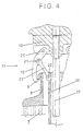
- Figure 4 is a detailed view that shows an example of a mechanical actuator for the release of the control bars.
- With reference to figures 1 and 2, there is shown, in the non-operative and in the operative state, respectively, the thermal sensor, generally shown in 1 of the mechanism according to the present invention realized as a bimetal pair of the kind that entails the development of an axial force as a function of temperature.
- The
thermal sensor 1 comprises afirst bar 2 the upper end of which is fastened to a rigid structure S while the opposed lower end is fastened to the lower end of asecond bar 3, spaced from and parallel to the first one, the upper end of the second bar being free. - The first and the
second bars second bar 3 is substantially greater than that of thefirst bar 2, and as a consequence, following a variation of the temperature, different elongation will occur in the two abovesaid bars, and more precisely, the elongation of thesecond bar 3 will be greater than that of thefirst bar 2, as it can be appreciated from figure 2. - The relative elongation of the
second bar 2 that intrinsecally can not be prevented or suppressed, will produce an axial force which is utilized, according to the present invention for performing automatically, in the event of an increase of the temperature of the cooling fluid, the release of the control bars in the way that will be better explained hereinafter. - Passing to study figure 3, wherein the mechanism according to the invention is shown schematically and mounted at the interior of the nuclear reactor, there are shown in 4 and 5, respectively, the upper and lower plates of the core of the nuclear reactor, in 6 the fuel elements, in 7 a bundle of control bars fastened to a
upper support plate 8. - From opposite sides of the
support plate 8 there protrude in the upper part of the same twobrackets 9 with which there are engagedrespective hooks 10 that, in this way, support the bundle ofcontrol bars 7 in an "extracted" position, saidhooks 10 being associated to amechanical actuator 11 that will be better described hereinafter, supported by arigid structure 12 fastened to theupper plate 4 of the reactor. - In the figure 3, there is shown generally in 13 the thermal sensor, already shown schematically and disclosed with reference to figures 1 and 2, and constituted in this case by two
bars bar 14 is constituted, rigidly coupled in correspondence with their lower ends by means of aconnection member 16. - The upper ends of the
bars respective transmission rods rigid structure 12, fastened, as above said, to theupper plate 4 of the reactor, while the second one extends up to near theactuator 11 at a distance D from this latter, constituting the play or dead space existing when thethermal sensor 13 is in the non-operative condition. - The distance D may be adjusted as a function of the temperature for which the release is sought.
- It is to be stated immediately, that the
transmission rods bars sensor 13 will extend respectively up to the above mentioned respective positions of the upper ends of thetransmission rods - In figure 4 there is shown an example of structural arrangement of a system for holding the bundle of control bars in the suspended, extracted condition, as well as of a mechanical actuator for releasing said bars allowing their fall under the force of gravity following the actuation by the thermal sensor when the same owing to the increase of temperature of the cooling fluid, passes into the actuated condition.
- Said system for holding the bundle of
bars 7 in the suspended condition comprises twohooks 10, symmetrical with respect to the axis of the bundle ofcontrol bars 7, of which hooks only one is shown in the figure, in register with respective opposite sides of thesupport plate 8 of the bundle ofcontrol bars 7, suitable for engagement withrespective brackets 9 protruding above from theplate 8, for supporting said control bars in said extracted position. Each of saidhooks 10 has the end opposite to the one in engagement with therespective bracket 9 of theplate 8, pivoted in 20 onto therigid structure 12 which is part of the reactor and in an intermediate position is rotatably connected by means of thepin 21 to an end of a swinging lever 22, that constitutes in this case said actuator, the opposite end of which is connected rotatably by means of thepin 23 to the upper end of thetubular transmission rod 18 that, being concentrical as above said externally with respect to therod 17, has the lower end fastened to the upper end of thebar 15 having a coefficient of thermal expansion greater than that of thebar 14 of thethermal sensor 13. - In the operation, with the
thermal sensor 13 introduced in the interior of thefuel element 6 in a central position where instrumentation components are located, when the temperature increases beyond a predetermined limit, thebar 15 of thethermal sensor 13, owing to such temperature increase, will undergo, as above explained, an elongation which causes an elevation of thetransmission rod 18 and the operation of theactuator 11 entailing the counterclockwise rotation of the articulated levers 22 around thepins 23 that connect them to the transmission rod 18 (see fig. 4) and consequently the clockwise rotation of therespective hooks 10 around thepins 20 moving away from the engagement with therespective brackets 9 on theplate 8 releasing in this way this latter and allowing consequently the fall of thecontrol bars 7 under the action of the force of gravity. - As an alternative, it should be stated here that, contrary to what has been said before, while maintaining the arrangememt shown in fig. 3, the
thermal sensor 13 may have theinternal bar 14 realized with a material having a coefficient of thermal expansion greater than that of the material of theexternal bar 15, in such case the operation of theactuator 11, when the temperature increses above the predetermined limit, will not occur following the lifting of thebar 18 fastended to thebar 15, but following the pulling downwards of the same following the elongation in said direction of thebar 14, the lower end of which is fastened, as above said, to the corresponding end of thebar 15. - With the
thermal sensor 13 built as above described, the structure of theactuator 11 will have obviously, to be modified and, in particular, in the example of figure 4, the linkage referred to, themembers rod 18 will result in a disengagement of thehook 10 from thebracket 9 of thesupport plate 8 of the bundle ofcontrol bars 7. - From the above, one may appreciate the noteworthy advantage below referred to of the mechanism of the invention with respect to the conventional systems of the same kind used up to now:
- an extreme structural simplicity
- an absolute operation reliability
- capability of operating the release of the control bars in an automatic and autonomous way as a function solely of the reaching of a predetermined absolute value of the temperature of the cooling fluid
- elimination of the presence of external sources of energy or power supply;
- capability of performing the release (scram) by means of a force developed autonomously at the interior of the actuator by the sole effect of the increase of the absolute temperature of the cooling fluid;
- mechanical continuity of its internal components and consequently with the exclusion of electrical or electronic interfaces of any kind, so that between the thermal sensor which produces a force and the mechanical members for the release of the control bars there are only rigid mechanical structures integrally coupled each other.
- Finally, it should be remarked that the mechanism according to the present invention, besides its particular application in the nuclear field, may find other advantageous applications, with suitable modifications, in the industrial field generally considered; for instance, for realizing safety valves to be placed side to side with respect to the conventional safety valves with spring threshold, with a particular reference to the field of the chemical-thermal industry.
- The threshold valves up to now prescribed by the control authorities are actuated by the internal pressure of the vessels to be protected. The valves that may be introduced with the thermal sensor according to the present invention will be, on the contrary, actuated by the temperature at the interior to the vessel to be protected. In this sense the new valves cooperate with the existing ones increasing the possibility of choice by the control authorities or by the designers of thermal chemical plants.
Claims (5)
- A mechanism for the automatic release of control bar means (7) in a nuclear reactor, comprising: a thermal sensor (13) apt to generate a mechanical force in an autonomous way as a function of the absolute temperature of the cooling fluid contacting the nuclear fuel in said reactor, said thermal sensor (13) comprising a first bar (14) and a second bar (15), parallel to and spaced from each other with concentrical symmetry, made with materials having different respective coefficients of thermal expansion; a holding and releasing device (10, 11) apt to engage in a releasable way said control bar means (7) in a suspended and spaced position above the fuel elements (6) of said nuclear reactor when this latter is in a normal operating condition, whereby the thermal sensor comprises means (15, 18) for actuating said holding and releasing device, when the temperature of the cooling fluid reaches a predetermined value, thereby causing the release of said control bar means, said mechanism being characterized by that said thermal sensor (13) is adapted to be fastened in a spatially fixed position to a rigid structure (12) of said reactor by connecting means (19), said spatially fixed position being inside a fuel element and therefore in immediate and full contact with the zone of heat production of the reactor, said first bar (14) of the thermal sensor (13) is a solid bar.
- A mechanism according to claim 1, wherein said holding and releasing device (10, 11) of said bundle (7) of control bars, in a suspended and spaced position above the fuel elements (6) of said nuclear reactor when this latter is in a normal operating position, comprises at least one hook (10) associated with a mechanical actuator (11), the upper end of said hook being supported in a rotatable way on said rigid structure (12) of said reactor, while the opposite end of said hook is arranged for engagement with a support (8) of said bundle (7) of control bars, said mechanical actuator (11) being apt to unlock said at least one hook (10) from the engagement with said bundle (7) of control bars so as to cause their fall under the force of gravity following the actuation by said thermal sensor (13), when said temperature of the cooling fluid of the nuclear fuel in said reactor reaches a predetermined value.
- A mechanism according to claim 2, wherein said mechanical actuator (11) comprises a hinged lever system (22) one end of which is pivoted on the upper end of said second bar (15) of said thermal sensor (13), while the other end is pivoted in an intermediate position (21) on said at least on hook (10).
- A mechanism according to claim 1, wherein transmission means (17, 18) are provided for transmitting to said holding and releasing means (10, 11) the mechanical force developed by said thermal sensor (13).
- A mechanism according to claim 4, wherein said transmission means are formed by a first rod (17) and a second rod (18), the lower ends of which are fastened to the respective upper ends of said first (14) and second (15) bars of said thermal sensor (13), the upper end of said first rod (17) being fastened to said rigid structure (12) of said reactor while the upper end of said second rod (18) is free and arranged for operating said mechanical actuator (11) by the differential thermal elongation between said first (14) and second (15) bar of said thermal sensor (13) when a temperature change occurs.
Applications Claiming Priority (2)
| Application Number | Priority Date | Filing Date | Title |
|---|---|---|---|
| IT4784489 | 1989-04-13 | ||
| IT8947844A IT1231553B (en) | 1989-04-13 | 1989-04-13 | AUTOMATIC RELEASE MECHANISM FOR CONTROL BARS IN A NUCLEAR REACTOR |
Publications (2)
| Publication Number | Publication Date |
|---|---|
| EP0392991A1 EP0392991A1 (en) | 1990-10-17 |
| EP0392991B1 true EP0392991B1 (en) | 1994-10-12 |
Family
ID=11262884
Family Applications (1)
| Application Number | Title | Priority Date | Filing Date |
|---|---|---|---|
| EP90830150A Expired - Lifetime EP0392991B1 (en) | 1989-04-13 | 1990-04-06 | A mechanism for the automatic release of control bars in a nuclear reactor |
Country Status (4)
| Country | Link |
|---|---|
| US (1) | US5059386A (en) |
| EP (1) | EP0392991B1 (en) |
| DE (1) | DE69013208T2 (en) |
| IT (1) | IT1231553B (en) |
Families Citing this family (4)
| Publication number | Priority date | Publication date | Assignee | Title |
|---|---|---|---|---|
| DE4212284A1 (en) * | 1992-04-11 | 1993-10-14 | Kernforschungsz Karlsruhe | An automatic shut=down device for nuclear, esp. sodium cooled, reactors - based on an expansion device driven by coolant temperature rises |
| DE4441751C1 (en) * | 1994-11-23 | 1996-04-25 | Siemens Ag | Rapid shutdown system and method for rapid shutdown of a nuclear reactor |
| FR2983625B1 (en) * | 2011-12-02 | 2014-02-07 | Commissariat Energie Atomique | DEVICE FOR TRIGGERING AND INSERTING ABSORBENT AND / OR MITIGATOR ELEMENTS IN A FISSILE AREA OF A NUCLEAR REACTOR AND ASSEMBLING NUCLEAR FUEL COMPRISING SUCH A DEVICE |
| CN112102970B (en) * | 2019-12-24 | 2021-04-23 | 四川大学 | Control rod driving mechanism and reactor control system |
Family Cites Families (13)
| Publication number | Priority date | Publication date | Assignee | Title |
|---|---|---|---|---|
| GB872092A (en) * | 1958-09-08 | 1961-07-05 | Nuclear Power Plant Co Ltd | Improvements in and relating to safety release mechanisms |
| US3546996A (en) * | 1969-04-10 | 1970-12-15 | Atomic Energy Commission | Release latch actuated by temperature excursion |
| US3992257A (en) * | 1975-08-13 | 1976-11-16 | The United States Of America As Represented By The United States Energy Research And Development Administration | Neutron-absorber release device |
| US3976543A (en) * | 1975-11-14 | 1976-08-24 | The United States Of America As Represented By The United States Energy Research And Development Administration | Temperature actuated shutdown assembly for a nuclear reactor |
| US4227967A (en) * | 1977-06-03 | 1980-10-14 | Electric Power Research Institute, Inc. | Method and apparatus for reducing the power level in a nuclear reactor during temperature transient |
| US4204909A (en) * | 1977-06-10 | 1980-05-27 | Combustion Engineering, Inc. | Temperature sensitive self-actuated scram mechanism |
| DE3362746D1 (en) * | 1982-01-28 | 1986-05-07 | Atomic Energy Authority Uk | Thermally responsive trigger devices and their use in shut-down devices for nuclear reactors |
| US4587085A (en) * | 1983-08-15 | 1986-05-06 | The United States Of America As Represented By The United States Department Of Energy | Nuclear reactor safety device |
| US4654192A (en) * | 1984-03-13 | 1987-03-31 | The United States Of America As Represented By The United States Department Of Energy | Temperature actuated automatic safety rod release |
| US4762662A (en) * | 1985-10-31 | 1988-08-09 | Rockwell International Corporation | Thermally activated trigger device |
| US4713210A (en) * | 1985-11-18 | 1987-12-15 | General Electric Company | Control rod driveline and grapple |
| GB8707614D0 (en) * | 1987-03-31 | 1987-05-07 | Nat Nuclear Corp Ltd | Reactivity control in nuclear reactors |
| DE3811581A1 (en) * | 1988-04-07 | 1989-10-19 | Peter Dr Rieckmann | Safety device for graphite moderated nuclear reactors |
-
1989
- 1989-04-13 IT IT8947844A patent/IT1231553B/en active
-
1990
- 1990-04-06 DE DE69013208T patent/DE69013208T2/en not_active Expired - Fee Related
- 1990-04-06 EP EP90830150A patent/EP0392991B1/en not_active Expired - Lifetime
- 1990-04-13 US US07/508,640 patent/US5059386A/en not_active Expired - Fee Related
Also Published As
| Publication number | Publication date |
|---|---|
| IT8947844A0 (en) | 1989-04-13 |
| DE69013208D1 (en) | 1994-11-17 |
| DE69013208T2 (en) | 1995-05-18 |
| EP0392991A1 (en) | 1990-10-17 |
| US5059386A (en) | 1991-10-22 |
| IT1231553B (en) | 1991-12-17 |
Similar Documents
| Publication | Publication Date | Title |
|---|---|---|
| US5059386A (en) | Mechanism for the automatic release of control bars in a nuclear reactor | |
| US4793964A (en) | Small natural circulation pressurized water nuclear reactor | |
| US3992257A (en) | Neutron-absorber release device | |
| US4204909A (en) | Temperature sensitive self-actuated scram mechanism | |
| JPS5823914B2 (en) | Support device for neutron absorber | |
| US4836443A (en) | Temperature-dependent pressure release device for pressure vessels | |
| EP0285258A2 (en) | Reactivity control in nuclear reactors | |
| US3278385A (en) | Reactor control rod drive mechanism | |
| WO1996012994A1 (en) | Passively ambient temperature actuated fluid valve | |
| US3164526A (en) | Reel type control rod brake | |
| US3364120A (en) | Nuclear control rod actuator | |
| GB872092A (en) | Improvements in and relating to safety release mechanisms | |
| RU2304314C2 (en) | Thermally responsive device | |
| EP0221298B1 (en) | Thermally activated trigger device | |
| US3120480A (en) | Control rod for nuclear reactors | |
| RU2057376C1 (en) | Fast reactor passive shielding device | |
| EP3857568A1 (en) | Control rod drive mechanism with heat pipe cooling | |
| CN116130122A (en) | Automatic power control system for heat pipe cooling reactor | |
| RU2072570C1 (en) | Device for passive protection of fast neutron nuclear reactor | |
| RU2260211C1 (en) | System for vessel nuclear reactor control and two-position switch of the passive protection of a nuclear reactor (nr) | |
| CN220984183U (en) | Water tank device of nuclear reactor containment and nuclear reactor containment equipment | |
| SU1291777A1 (en) | Three-way quick-acting valve for steam generator | |
| Gilbertson et al. | Control rod release mechanism | |
| Edelmann et al. | Improved fast reactor safety by passive shut-down | |
| RU2012073C1 (en) | Device for passive protection of nuclear reactor |
Legal Events
| Date | Code | Title | Description |
|---|---|---|---|
| PUAI | Public reference made under article 153(3) epc to a published international application that has entered the european phase |
Free format text: ORIGINAL CODE: 0009012 |
|
| AK | Designated contracting states |
Kind code of ref document: A1 Designated state(s): DE FR GB SE |
|
| 17P | Request for examination filed |
Effective date: 19910408 |
|
| RAP1 | Party data changed (applicant data changed or rights of an application transferred) |
Owner name: ENTE PER LE NUOVE TECNOLOGIE, L'ENERGIA E L'AMBIEN |
|
| 17Q | First examination report despatched |
Effective date: 19930528 |
|
| GRAA | (expected) grant |
Free format text: ORIGINAL CODE: 0009210 |
|
| AK | Designated contracting states |
Kind code of ref document: B1 Designated state(s): DE FR GB SE |
|
| REF | Corresponds to: |
Ref document number: 69013208 Country of ref document: DE Date of ref document: 19941117 |
|
| EAL | Se: european patent in force in sweden |
Ref document number: 90830150.0 |
|
| ET | Fr: translation filed | ||
| PGFP | Annual fee paid to national office [announced via postgrant information from national office to epo] |
Ref country code: GB Payment date: 19950228 Year of fee payment: 6 |
|
| PGFP | Annual fee paid to national office [announced via postgrant information from national office to epo] |
Ref country code: FR Payment date: 19950329 Year of fee payment: 6 |
|
| PGFP | Annual fee paid to national office [announced via postgrant information from national office to epo] |
Ref country code: SE Payment date: 19950411 Year of fee payment: 6 |
|
| PGFP | Annual fee paid to national office [announced via postgrant information from national office to epo] |
Ref country code: DE Payment date: 19950531 Year of fee payment: 6 |
|
| PLBE | No opposition filed within time limit |
Free format text: ORIGINAL CODE: 0009261 |
|
| STAA | Information on the status of an ep patent application or granted ep patent |
Free format text: STATUS: NO OPPOSITION FILED WITHIN TIME LIMIT |
|
| 26N | No opposition filed | ||
| PG25 | Lapsed in a contracting state [announced via postgrant information from national office to epo] |
Ref country code: GB Effective date: 19960406 |
|
| PG25 | Lapsed in a contracting state [announced via postgrant information from national office to epo] |
Ref country code: SE Effective date: 19960407 |
|
| GBPC | Gb: european patent ceased through non-payment of renewal fee |
Effective date: 19960406 |
|
| PG25 | Lapsed in a contracting state [announced via postgrant information from national office to epo] |
Ref country code: FR Effective date: 19961227 |
|
| PG25 | Lapsed in a contracting state [announced via postgrant information from national office to epo] |
Ref country code: DE Effective date: 19970101 |
|
| EUG | Se: european patent has lapsed |
Ref document number: 90830150.0 |
|
| REG | Reference to a national code |
Ref country code: FR Ref legal event code: ST |