EP0392828A2 - Railway car body and its method of manufacture - Google Patents
Railway car body and its method of manufacture Download PDFInfo
- Publication number
- EP0392828A2 EP0392828A2 EP90303922A EP90303922A EP0392828A2 EP 0392828 A2 EP0392828 A2 EP 0392828A2 EP 90303922 A EP90303922 A EP 90303922A EP 90303922 A EP90303922 A EP 90303922A EP 0392828 A2 EP0392828 A2 EP 0392828A2
- Authority
- EP
- European Patent Office
- Prior art keywords
- underframe
- car body
- center
- joining
- flange
- Prior art date
- Legal status (The legal status is an assumption and is not a legal conclusion. Google has not performed a legal analysis and makes no representation as to the accuracy of the status listed.)
- Granted
Links
Images


Classifications
-
- B—PERFORMING OPERATIONS; TRANSPORTING
- B61—RAILWAYS
- B61D—BODY DETAILS OR KINDS OF RAILWAY VEHICLES
- B61D17/00—Construction details of vehicle bodies
- B61D17/04—Construction details of vehicle bodies with bodies of metal; with composite, e.g. metal and wood body structures
-
- B—PERFORMING OPERATIONS; TRANSPORTING
- B61—RAILWAYS
- B61D—BODY DETAILS OR KINDS OF RAILWAY VEHICLES
- B61D17/00—Construction details of vehicle bodies
-
- B—PERFORMING OPERATIONS; TRANSPORTING
- B61—RAILWAYS
- B61D—BODY DETAILS OR KINDS OF RAILWAY VEHICLES
- B61D17/00—Construction details of vehicle bodies
- B61D17/04—Construction details of vehicle bodies with bodies of metal; with composite, e.g. metal and wood body structures
- B61D17/041—Construction details of vehicle bodies with bodies of metal; with composite, e.g. metal and wood body structures with bodies characterised by use of light metal, e.g. aluminium
-
- B—PERFORMING OPERATIONS; TRANSPORTING
- B61—RAILWAYS
- B61D—BODY DETAILS OR KINDS OF RAILWAY VEHICLES
- B61D17/00—Construction details of vehicle bodies
- B61D17/04—Construction details of vehicle bodies with bodies of metal; with composite, e.g. metal and wood body structures
- B61D17/043—Construction details of vehicle bodies with bodies of metal; with composite, e.g. metal and wood body structures connections between superstructure sub-units
-
- B—PERFORMING OPERATIONS; TRANSPORTING
- B61—RAILWAYS
- B61D—BODY DETAILS OR KINDS OF RAILWAY VEHICLES
- B61D17/00—Construction details of vehicle bodies
- B61D17/04—Construction details of vehicle bodies with bodies of metal; with composite, e.g. metal and wood body structures
- B61D17/10—Floors
-
- Y—GENERAL TAGGING OF NEW TECHNOLOGICAL DEVELOPMENTS; GENERAL TAGGING OF CROSS-SECTIONAL TECHNOLOGIES SPANNING OVER SEVERAL SECTIONS OF THE IPC; TECHNICAL SUBJECTS COVERED BY FORMER USPC CROSS-REFERENCE ART COLLECTIONS [XRACs] AND DIGESTS
- Y02—TECHNOLOGIES OR APPLICATIONS FOR MITIGATION OR ADAPTATION AGAINST CLIMATE CHANGE
- Y02T—CLIMATE CHANGE MITIGATION TECHNOLOGIES RELATED TO TRANSPORTATION
- Y02T30/00—Transportation of goods or passengers via railways, e.g. energy recovery or reducing air resistance
Definitions
- the present invention relates to a car body of railway rolling stock and a method for fabricating a car body and, more particularly, to a car body of railway rolling stock and a method for fabricating a car body suitable for passenger cars or electric passenger cars.
- car bodies of rolling stock are produced of light alloys such as aluminum alloys, steel for structural use or stainless steel materials.
- the whole body has been made up mainly of one kind of material.
- a car body produced of a stainless steel material has a long life because the stainless steel is less liable to corrosion than aluminum alloy and steel for structural use.
- a stainless steel body requires a special surface treatment of its outer places when the body surface is to be painted. Therefore, the stainless steel body requires much time and labour for painting work.
- a car body built of an aluminum alloy material is light in weight and easy to paint the body.
- an aluminum alloy is much more expensive than stainless steel. Therefore the material cost of aluminum alloy car body is much bigger than that of stainless steel body and body built of steel for structural use.
- the steel material for structural use is susceptible to corrosion as compared with the stainless steel and heavier than the aluminum alloy material.
- the car body built of steel for structural use is heavier than the aluminum alloy body and has a shorter service life than the stainless steel body.
- the plurality of the extruded shapes of aluminum alloy extend in the longitudinal direction of the car body, being arranged in parallel with the direction of width of the car body and joined with one another by welding.
- a side framing is constituted of a stainless steel material or a steel material for structural use.
- a car body using an underframe made up of the extruded shapes of aluminum alloy joined with the side framing is known.
- Such a car body of the above-described constitution has been disclosed in for example Japanese Laid-Open Utility Model No. 60-108584.
- the whole body of the underframe is composed of extruded shapes of aluminum alloy, without giving a due consideration to the reduction of a material cost fabricating the underframe itself.
- a first object of the present invention is to provide a car body of railway rolling stock capable of minimizing a material cost of the whole car body and facilitating the mounting of various kinds of equipment to be mounted on the undersurface of an underframe.
- a second object of the present invention is to provide a car body of railway rolling stock capable of preventing a trouble likely to be caused by corrosion in addition to the first object.
- a third object of the present invention is to provide a car body of railway rolling stock capable of facilitating the painting of at least car body sides in addition to the first or the second object.
- the underframe is composed of a center underframe formed of extruded shapes of a light alloy and end underframe formed of a ferrous material.
- the center and end underframes are connected by a coupling means at each longitudinal end of the car body.
- the present invention can also provide, in the underframe, a coupling means capable of smoothly transmitting, between the center underframe and the end underframe, a car end load passing to the underframe through a coupler.
- Another available feature of the present invention is, in the underframe, to decrease the weight of a side sill by decreasing the plate thickness of the side sill constituting the end underframe, by transmitting the car end load by the center underframe.
- Another feature of the present invention is, in the underframe, to reduce the weight of the whole body of the underframe.
- an underframe 1 constitutes the undersurface of the car body.
- a side framing 40 constitutes both sides of the car body.
- a roof framing 60 constitutes an upper surface, or a roof section, of the car body.
- an end frame 70 constitutes car body ends in the longitudinal direction of the car body.
- the side framing 40 is made up of such side frames as side posts 41, studs 42, door posts 43, stiffeners 44, rocker rails 45, belt rails 46, window heads 47 and cant rails 48, which are combined and joined through joining members 49, and by joining a side outer plate 50 on the outside of these side frame members.
- the side frame members and the side outer plate 50 are produced of steel for structural use.
- the roof framing 60 is constituted by assembling and joining such roof frame members as cant rails 61 and carlines 62, and also by joining roof outer plate 63 on the outside of these roof frame members.
- the roof outer plates 63 are stainless steel plates, which have corrugated sections.
- the roof frame members are produced from stainless steel or steel for structural use.
- the end framing 70 is constituted by assembling end frame members such as corner posts, end posts, end places and stiffeners and by joining them through joining members and also by joining end outer places to the outside of these end frame members.
- the end frame members and the end outer places are produced of steel for structural use. The detailed construction of the end framing 70 is not illustrated.
- the underframe 1 is composed of a center underframe 2 and an end underframe 3.
- the center underframe 2 is built by parallelly joining a plurality of extruded shapes 4 of aluminum alloy.
- the extruded shapes 4 extend in the longitudinal direction of the car body of the underframe, being parallelly arranged in the direction of width of the car body, on the underframe.
- the extruded shape 4 has a hollow part 4a inside, and is formed integral with an equipment attaching rail 4b for supporting various equipment such as control equipment or air-conditioning apparatus on the undersurface.
- the end underframe 3 is composed of side sills 5, end beams 6, center sills 7, 8, a body bolster 9, cross beams 10 and a floor member 11.
- the two side sills 5 extending in the longitudinal direction of the car body are arranged at both ends of the underframe in the direction of width of the car body, these ends being connected by the two end beams 6.
- the body bolster 9 is located close to the center of the underframe in the longitudinal direction of the car body rather than the end beams 6. This body bolster 9 is disposed correspondingly to the center of the truck.
- the two center sills 7 are disposed parallelly with the side sills 5 between the end beams 6 located at both ends of the underframe in the longitudinal direction of the car body and the body bolster 9.
- Each end of these center sills is joined to the end sill 6 and the body bolster 9.
- a spacing between the two center sills is wide enough to install a coupler therebetween.
- the two cross beams 10 are disposed parallelly with the body bolsters 6 between the two side sills 6, with their ends connected to the side sills.
- the cross beams 10 are arranged close to the center of the underframe in the longitudinal direction of the car body rather than the body bolster 9.
- the side sills 5, the end beams 6, the center sills 7, 8, the body bolster 9 and the cross beams 10 are produced of steel for structural use or stainless steel.
- the floor member 11 is installed to cover the upper surface of the center sills 7, 8, the body bolster 9 and the cross beams 10 which are located between the two side sills 5.
- the floor member 11 is constituted of a keystone plate 11a produced of steel for structural use or stainless steel.
- a keystone plate 1b is a joining member for joining the keystone plate 11a with the center underframe 2 and has also a function as a floor member.
- the keystone plates 11a and 11b have a corrugated section in the direction of width of the car body.
- One end of the keystone plate 11a in the longitudinal direction of the car body is connected to the end beam 6, while the other end in the longitudinal direction of the car body is mounted on the upper surface of the cross beam 10.
- One end of the keystone plate 11b in the longitudinal direction of the car body is connected by welding to the end of the center underframe 2 in the longitudinal direction of the car body, and the other end in the longitudinal direction of the car body extends as far as the upper surface of the cross beam 10.
- the keystone plates 11a and 11b are overlapped above the cross beam 10, being joined by rivets 12 to the upper flange of the cross beam 10.
- the rivets 12 are joining means, which may be substituted for by for example blind rivets, bolts and nuts, and rivet bonding.
- the extruded shape 4 located adjacent to the side sill 5 is formed integral with a flange 4c, which is coupled with an upper flange 5a of the side sill 5.
- the flange 4c and the upper flange 5a are joined by blind rivets 13.
- the end in the direction of width of the car body of the extruded shape 4 located adjacent to the side sill 5 and a lower flange 5b of the side sill 5 are connected by means of a coupling member 14.
- the coupling member 14 has a "Z" section. The coupling member 14 and the extruded shape 4 and the lower flange 5b are joined by the blind rivets 13.
- a hole 4d is provided in the extruded shape 4 for the insertion of the blind rivet 13.
- the coupling member 14 has a hole 14a, which is used for joining by spot welding a rocker rail 45 constituting the side framing 40 and the side sill 5 in a position indicated by the arrow W.
- the blind rivets 13 are joining means, which may be substituted for by for example rivets, bolts and nuts, and rivet bonding.
- the coupling member 14 may be produced of any one of steel for structural use, stainless steel, and aluminum alloy. Also the coupling 24 of steel for structural use or a stainless steel can be directly joined by welding to the lower flange 5b. Further, the coupling member 14 of aluminum alloy can be jointed directly by welding to the lower surface or the side surface of the extruded shape 4.
- the steel for structural use usable for the coupling members 14 described above are for example steel for general structures, steel for weather-proof structures, high-tension steel, and steel for welded structures.
- Stainless steel includes for example austenitic stainless steel. Also light alloys that can be used are JIS A6063, 6NO1, etc.
- the center underframe 2 is fitted in a space enclosed by the two side sills 5 and two cross beams 10 of the end underframe 3. Then, the flange 4c of the extruded shape 4 and the upper flange 5a of the side sill 5 are connected by the blind rivet 13. A hole is drilled in the overlapped section of the keystone plate 11a, the keystone plate 11b and the upper flange of the cross beam 5, and the rivet member is inserted in the hole. The keystone plate 11a, the keystone plate 11b, and the upper flange of the cross beam 5 are connected by the rivet member, thus completing the underframe 1.
- the side framing 40, the roof framing 60, and the end framing 70 are fabricated separately from the underframe 1.
- the underframe 1, the side framing 40, the roof framing 60 and the end framing 70 thus fabricated are assembled by the following procedure. That is, the side framing 40 is disposed on the upper surface of either end of the underframe 1 in the direction of width of the car body, and the end framing 70 is disposed on the upper surface of either end of the underframe 1 in the longitudinal direction of the car body. Joining between the underframe 1 and the side framing 40, between the underframe 1 and the end framing 70, and between the side framing 40 and the end framing 70 is done by spot welding. Furthermore, the roof framing 60 is disposed above the side framing 40 and the end framing 70.
- the various kinds of members constituting the car body are made up at least of three kinds of materials, thereby enabling the reduction of weight of the car body more than conventional car bodies of steel for structural use and at a lower material cost than light-alloy car bodies.
- constituting the center underframe 2 of a plurality of light-alloy extruded shapes can build the underframe 1 of greater rigidity and lighter weight than conventional underframes of steel for structural use that bear the same degree of car-end load.
- the equipment attaching rail 4b is formed integral with each extruded shape 4, lt ls possible to decrease the number of component parts of the underframe 1, simplify the construction of the underframe, and decrease the number of fabrication processes of the underframe 1, thereby enabling cost and weight reduction of the whole car body.
- the end underframe 3 is built of a steel for structures or stainless steel of lower price than the light-alloy material. Accordingly, the underframe 1 can be produced at a lower material cost than the underframe the whole body of which is built of the light-alloy material. Also it is possible to prevent the end underframe 3 from corrosion by producing it of a stainless steel. This constitution will be effective when a lavatory or a toilet is set at the end in the longitudinal direction of the car body.
- the side framing 40, roof framing 60 and end framing 70 of the car body of the present invention are produced of an inexpensive steel for structures or a stainless steel, the material cost of the whole car body can be diminished as compared with conventional light-alloy bodies.
- the roof outer places 63 are produced of a stainless steel. Because the stainless steel is not liable to corrosion, it is unnecessary to take corrosion prevention into consideration and use thicker roof outer places 63, thereby achieving the reduction of weight of the roof framing 60.
- the weight of the roof framing can be decreased by using fiber-reinforced plastic (FRP) roof outer places.
- FRP fiber-reinforced plastic
- the side outer places 50 of the side framing 40 and the end outer places of the end framing 70 which are produced of steel for structures can be painted without a special surface treatment because of better paintability of the outer places of the steel for structure than the stainless outer places. Therefore, much labour and time are not required for painting the side framing 40 and end framing 70 of the car body.
- the car body produced of the steel for structural use can fully meet varieties of requirements as to car body design.
- the center underframe 2 of the underframe 1 is produced of a plurality of extruded shapes of aluminum alloy.
- the weight of the underframe can be reduced more than the underframe 1 by using many light-alloy cross beams in place of the center underframe 2 in parallel with the body bolster 10 between the side sills 5. Further, it is possible to decrease the cost of the underframe and the car body by using, for the end underframe, a steel for structures and a stainless steel of lower cost than the light-alloy material.
- the joining section of the extruded shape 4 and the side sill 5 has a box-like sectional form having improved rigidity and durability.
- the box-like sectional form of the joining section of the extruded shape 4 and the side sill 5 it is likely that rain water will accumulate therein. It is, therefore, desirable to make the side sills 5 and the coupling member of stainless steel. It is also desirable to provide the side sill with a water drain hole where there is the possibility of water accumulation in the joining section between the extruded section 4 and the side sill 5 as described above.
- Joining between the underframe 1 and the side framing 40 that is, joining between the side outer plate 50 and the rocker rail 45 and the side sill 5 are effected by spot welding.
- Plug welding is performed in a joining section, or a body bolster mounting position, between the underframe 1 and the side framing 40, where the spot welding electrode can not be inserted. Since the underframe 1 and the side framing 40 are joined principally by spot welding as described above, joining workability can be improved. It is also possible to lessen distortion occurring in the side framing 40, particularly in the side outer places 50.
- the car-end load acting on one coupler of the underframe is transmitted to the other coupler of the underframe not only along the side sill 5 but along the center underframe 2, thereby enabling the reduction of the car-body load the side sill 5 bears and a decrease in the plate thickness and weight of the side sill 5 itself.
- the end underframe having the body bolster 9 which transmits the vertical load of the whole car body to the truck is produced of the steel for structural use as described above. Since the underframe 1 is built of high-rigidity material as compared with the underframe the whole body of which is produced of a light-alloy material, the body bolster itself and its surrounding construction can be simplified.
- the embodiment shown in Fig. 7 differs from the first embodiment previously described, in the construction of the extruded shape 104 equivalent to the extruded shape 4 used in the first embodiment and the construction of the coupling member 114 equivalent to the coupling member 14 in the first, embodiment.
- the same reference numerals as those used in the first embodiment denote the same members as those illustrated in the first embodiment.
- the extruded shape 104 is formed integral with a joining flange 104e extending towards the web of the side sill 5, in a lower position where the extruded shape 104 comes in contact with the side sill 5.
- the flange 104e extends obliquely downwardly.
- the extruded shape 104 has a similar construction as the extruded shape 4 of the first embodiment except for the joining flange 104e.
- the flange 104e has a hole 104f formed for a blind rivet.
- the coupling member 114 is formed nearly in the L section.
- the coupling section 114 is arranged such that one flat section will overlap with the inner surface of the web of the side sill 5, while the other flat section will overlap the joining flange 104e.
- the coupling member 114 and the flange 104e are joined by the blind rivet 13 at their overlap section.
- the coupling member 114 and the cross beam 5 are joined by spot welding at their overlap.
- the joining of the coupling member 114 to the cross beam 5 is done together with spot-welding the rocker rail 45, the side outer plate 50 and the side sill 5.
- the center underframe is constituted of the extruded shapes 104
- the extruded shape 104 has the joining flange 104e, a center underframe completed by joining with other extruded shapes can not be inserted in between the side sills 5 of the end underframe. Therefore when the center underframe is constituted of the extruded shapes 104, it is necessary to install a plurality of extruded shapes simultaneously when building the end underframe.
- the joining section between the side sill 5 and the extruded shape 104 can be built into a box-like section, thus improving the rigidity of the joining section. Furthermore, since spot welding for joining the side sill 5 with the side framing 40 can be done without using an access hole, workability can be improved. Also, since a spot-welded part can directly visually be checked, the reliability of the joining section between the side sill 5 and the side framing 40 can be improved. Further it is possible to prevent the entrance of rain water into the joining section by closing the hole 104f after completing the joining between the side sill 5 and the side framing 40.
- the construction according to the present embodiment is effective particularly when using the side sills 5 produced from steel for structural purposes.
- the embodiment shown in Fig. 8 differs in the construction of the extruded shape 204 equivalent to the extruded shape 4 in the first embodiment and in the construction of the side sill 205 equivalent to the side sill appearing in the first embodiment.
- the same reference numerals as those used in the first embodiment denote the same members as those appearing in the first embodiment.
- the end face of the extruded shape 204 which comes in contact with the side sill 5 is formed perpendicular to the side sill 5. That is, the extruded shape 204 is not provided with the joining flange 4c, 104e.
- the side sill 205 has a joining section 205c formed for joining with the extruded shape 204 by projecting the web section toward the center side in the direction of width of the underframe.
- the joining section 205c is formed by bending a material for constituting the side sill 205.
- a conceivable method is to attach members forming the joining section 205c to the web of the side sill 205 by welding.
- the joining section 205c is joined by the blind rivet 13 to the end face of a part of the extruded shape 204 which comes in contact with the side silt 5.
- the extruded shape 204 has, a hole 205d for the blind rivet 13.
- the side framing 40 and the side sill 205 are joined by spot welding at the position indicated by the arrow W. Namely, the side sill 205 has a vertical web formed for spot welding.
- the side sill 205 having the joining section 205c on the web, has greater rigidity than the upper flange of the side sill. According to this embodiment, therefore, it is possible to improve the strength of the whole body of the underframe. Also according to this embodiment, it is unnecessary to join the extruded shape with the side sill by the coupling member as in the first embodiment. Further, the rigidity of the side sill 205 itself can be improved by forming the joining section 205c on the side sill 205. According to this embodiment, the end underframe and the center underframe, which are fabricated separately, can be jointed with ease.
- the center underframe constituted of the extruded shapes 204 can be inserted in between the side sills 205 installed between both aides of the end underframe in the direction of width, in either upward or downward direction of the end underframe. Furthermore, according to the present embodiment, the positional relation between the upper surface of the side sill 205 and the upper surface of the center underframe constituted of the extruded shapes 204 can be adjusted in the perpendicular direction.
- the construction of the side sill 305 equivalent to the side sill of the first embodiment differs from the first embodiment.
- the same reference numerals as those used in the first embodiment denote the same members as those appearing in the first embodiment.
- On the upper flange 305a of the side sill 305 is formed a rib 305d at the end section on the central side of the upper flange 305a in the direction of width of the underframe. This rib 305d is formed in parallel with the web of the side sill 305 by bending the forward end section of the upper flange 305a.
- the upper flange 305d can be improved in rigidity by forming a rib 305d thereon. Therefore, in the construction that the center underframe 4 and the side sill 305 are joined through the flange 4c, the upper flange 305a can be prevented from deformation.
- the rib 305d can be formed by bending the forward end of the upper flange 305a and therefore can easily be fabricated, the side sill 305 itself being of simple construction.
- the construction of the side sill 405 equivalent to the side sill of the first embodiment differs from that of the first embodiment.
- the same reference numerals used in the first embodiment denote the same members in the first embodiment.
- the extruded shapes of the present embodiment are nearly of the similar constitution as the extruded shapes shown in Fig. 8.
- the side sill 405 is provided with a support section 405e which supports the L-sectioned center underframe at the forward end section of the upper flange 405.
- the support section 405e supports the center underframe in the state that the upper surface of the center section 405e is flush with the upper surface of the side sill 405.
- the support section 405e and the center underframe 204 are joined by the blind rivet 13.
- the hale 204e is for mounting the blind rivet 13.
- a blind rivet capable of joining the support section 405e to the center underframe 204 from one side is used in place of the aforementioned blind rivet 13, it is unnecessary to make the hole 204e in the center underframe 204.
- the rigidity of the side sill 405 itself can be improved by forming the support section 405e on the side sill 405. Also it is possible to set the upper surface of the center underframe 204 flush with the upper surface of the side silt 405 simply by mounting the center underframe 204 on the support section 405e, thereby improving operation efficiency in fabricating the underframe.
- Figs. 11 to 17 show the construction of the joining section of the floor member and cross beam of the end under frame and the center underframe of the car body of railway rolling stock according to another embodiment of the present invention.
- the embodiments shown in Figs. 11 and 12 differs from the first embodiment in the construction of the joining members 20a and 20b and in the construction of the keystone plate 11a.
- the same reference numerals as those used in the first embodiment denote the same members appearing in the first embodiment.
- the center underframe 102 has basically the identical constitution as the center underframe 2 of the first embodiment.
- This joining member 20a produced of aluminum alloy, has a nearly T-form section and is welded to the center underframe 102 by welding.
- To the web of the cross beam 10 is joined the joining member 20b.
- This joining member 20b has a nearly L-shaped section and constituted of steel for structural use or stainless steel.
- the joining member 20b is joined to the cross beam 10 by welding, and has a function to support the center underframe 102 in relation to the cross beam 10, that is, a function as a support member.
- the end section of the keystone plate 11a on the center section side of the underframe in the longitudinal direction of the car body is extending to a position close to the center underframe 102 rather than the cross beam 10.
- the keystone plate 11a is overlapped vertically with the joining members 20a and 20b.
- On the upper surface of the keystone plate 11a is installed a patch 21 correspondingly to these overlapped sections, and a spacer 22 is installed between the keystone plate 11a and the joining member 20a.
- the patch 21, the keystone plate 11a, the spacer 22, the joining member 20a and joining member 20b are vertically overlappingly installed and joined all together by means of the blind rivet 13.
- An increased number of the blind rivets 13 are used near the center sill 8 as shown in Fig. 12.
- increasing the number of the blind rivets 13 facilitates the passage of the car-end load from the center sill 8 to the center underframe 102 or from the center underframe 102 to the center sill 8.
- a filling-up material 23 for the filling-up material 23.
- a polyurethane resin for example is used.
- the joining member 20a since the joining member 20a is installed between the keystone plate 11a and the joining member 20b, no moment will unnecessarily act on these joining sections. Therefore, if a great car-end load acts among the joining member 20a, the keystone plate 11a and the joining member 20b, these joining sections will not be subjected to deformation, thus providing a greater strength. Also, since a great car-end load can be transmitted among the center underframe 102, the keystone plate 11a and the cross beam 10, the car body load acting on the side sill can be decreased, and accordingly it is possible to decrease the plate thickness of the cross beam, thereby reducing the weight of the cross beam itself.
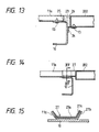
- Fig. 13 shows the construction of the joining section among the center underframe 202, the keystone plate 11a and the cross beam 10, which is different from that of the first embodiment.
- the same reference numerals used in the first embodiment denote the same members in the first embodiment.
- a support member 24 is attached to the web of the cross beam 10, supporting the end of the center underframe 202 in the longitudinal direction of the car body.
- the support member 24 and the end section of the center underframe 202 in the longitudinal direction are joined by the blind rivet 13.
- the keystone plate 11a and the cross beam 10 are joined by means of the blind rivet 13.
- the center underframe 202 has a cover plate 26 attached at the end face in the longitudinal direction of the car body.
- the keystone plate 11a has a cover plate 25, which is attached at the end face in the longitudinal direction of the car body. Between the cover plate 25 and the cover plate 26 is filled a filling-up material 23. This filling-up material 23 in a set state has strength great enough to transmit the car-end load between the end underframe and the center underframe 202.
- the joining section of the end underframe and the center underframe 202 is of a simple construction, thereby enabling easy fabrication of the underframe. Between the end underframe and the center underframe 202 is filled the filling-up material 23, and therefore any dimensional error, if present between these underframes, can easily be permitted. Further, the car-end load can be exactly transmitted through the filling-up material 23 between the end underframe and the center underframe 202.
- the embodiment shown in Figs. 14 and 15 differs from the first embodiment in the construction of the joining member 27 and the construction of the joining section among the joining member 27, the keystone plate 11a and the center underframe 202.
- the same reference numerals used in the first embodiment denote the same members appearing in the first embodiment.
- the joining member 27 is a clad member made by joining an aluminum alloy plate 27a and a plate 27 of stainless steel or steel for structural use by explosive bonding.
- the joining member 27 is made by inserting a brazing sheet 27c in between the plate 27a and the plate 27b and joining them by explosive bonding them together.
- This joining member 27 is produced by joining the places 27a and 27b and then by forming into a corrugated form correspondingly to the sectional form of the keystone plate 11a.
- the joining member 27 has both an overlapping part and a nonoverlapping part between the plate 27a and the plate 27b.
- the nonoverlapping part is joined by welding to the keystone plate 11a and the center underframe 202. Namely, the nonoverlapping part between the plate 27a and the plate 27b is joined to the center underframe 202 by welding. Also, a nonoverlapping part between the plate 27b and the plate 27a is joined to the keystone plate 11a by welding.
- the joining member 27 can easily be joined by welding the keystone plate 11a to the center underframe 202. Therefore, according to this embodiment, the end underframe and the center underframe 202 can be joined relatively easily by welding. Further, according to this embodiment, labour and time required in fabricating the underframe can be reduced.
- Fig. 16 shows the construction of the center underframe 302 and the keystone plate 111a, which differs from that of the first embodiment.
- the center underframe 302 has a cutout 302a at the end section in the longitudinal direction of the car body.
- the vertical size of the cutout 302a coincides with that of the keystone plate 111a. That is, when the end of the keystone plate 111a in the longitudinal direction of the car body is set in the cutout 302a, the upper surface of the center underframe 302 is flush with the upper surface of the keystone plate 111a.
- the cutout 302a is fitted with a cover plate 26.
- the end section of the keystone plate 111a in the longitudinal direction of the car body protrudes out towards the center underframe 30. Namely, the keystone plate 111a is longer in the longitudinal direction of the car body than the keystone plate 11a of the first embodiment.
- a cover plate 25 is attached at the end of the keystone plate 111a in the longitudinal direction of the car body. Between the cover plate 25 and the cover plate 26 is filled the filling-up material 23.
- the end of the center underframe 302 in the longitudinal direction of the car body is connected to the cross beam 10 through the support member 24. The center underframe 302 and the support member 24 are joined by the blind rivet 13.
- filling-up material 23 because of little amount of filling-up material 23 in addition to a similar effect as each of the embodiments described above, a car-end compression is exactly transmitted. Filling the filling-up material 23 permits a dimensional error of each member and also improves the airtightness of the car body.
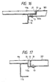
- Fig. 17 shows the construction of the cross beam 110, which differs from the first embodiment.
- the cross beam 110 is made with the upper flange 110a extended toward the center side of the underframe in the longitudinal direction of the car body.
- the upper flange 110a has a nearly Z-sectional form, supporting the end of the center underframe 202 in the longitudinal direction of the car body.
- the upper flange 110a is joined to the end of the center underframe 202 in the longitudinal direction of the car body by the blind rivet 13.
- the blind rivet 13 can be inserted from under the lower surface side of the upper flange 110a.
- the keystone plate 11a and the center underframe 202 are fitted with the cover places 25 and 26 at their end sections as viewed in the longitudinal direction of the car body. Between the cover plate 25 of the keystone plate 11a and the cover plate 26 of the center underframe is filled the filling-up material 23.
- the upper flange 110a supporting the center underframe 202 is formed integral with the cross beam 110, the number of component parts of the underframe can be decreased. Also according to this embodiment, the joining of the end underframe with the center underframe 202 is completed by joining the upper flange 110a with the center underframe 202 after placing the center underframe 202 on the upper surface of the upper flange 110a. Therefore, joining the end underframe with the center underframe 202 can easily be performed.
- the support section of the center underframe 202 is formed integral with the cross beam 110, but a part corresponding to the upper flange 110a or the support section of the center underframe 202 may be constituted of other members and joined by welding to the cross beam.
- a car body of railway rolling stock capable of minimizing the material cost of the whole car body and facilitating the mounting of various equipment on the undersurface of the underframe.
- a car body of railway rolling stock which, in addition to a plurality of effects described above, has an effect to facilitate painting of at least side surfaces of the car body.
Abstract
Description
- The present invention relates to a car body of railway rolling stock and a method for fabricating a car body and, more particularly, to a car body of railway rolling stock and a method for fabricating a car body suitable for passenger cars or electric passenger cars.
- Generally, car bodies of rolling stock are produced of light alloys such as aluminum alloys, steel for structural use or stainless steel materials. In the car bodies of rolling stock, the whole body has been made up mainly of one kind of material.
- A car body produced of a stainless steel material has a long life because the stainless steel is less liable to corrosion than aluminum alloy and steel for structural use. A stainless steel body, however, requires a special surface treatment of its outer places when the body surface is to be painted. Therefore, the stainless steel body requires much time and labour for painting work. A car body built of an aluminum alloy material is light in weight and easy to paint the body. However an aluminum alloy is much more expensive than stainless steel. Therefore the material cost of aluminum alloy car body is much bigger than that of stainless steel body and body built of steel for structural use. However, the steel material for structural use is susceptible to corrosion as compared with the stainless steel and heavier than the aluminum alloy material. The car body built of steel for structural use is heavier than the aluminum alloy body and has a shorter service life than the stainless steel body.
- There have recently been developed various technologies for joining different kinds of materials. Also there has been achieved improvement in the strength of the connecting section of materials, thereby enabling the combination of different kinds of materials, for example a light alloy material and a steel material for structural use. In the meantime, the number of railway cars equipped with control equipment and air-conditioning apparatus on the undersurface of an underframe has been increasing these days. In a car body described above, it is imperative to constitute the underframe such that the aforementioned various equipment can be mounted on the undersurface of the underframe as easily as possible. The underframe, therefore, is built of a plurality of extruded shapes of aluminum alloy formed integral with a rail sturdy enough to support the various equipment. The plurality of the extruded shapes of aluminum alloy extend in the longitudinal direction of the car body, being arranged in parallel with the direction of width of the car body and joined with one another by welding. A side framing is constituted of a stainless steel material or a steel material for structural use. A car body using an underframe made up of the extruded shapes of aluminum alloy joined with the side framing is known. Such a car body of the above-described constitution has been disclosed in for example Japanese Laid-Open Utility Model No. 60-108584. In this car body, the whole body of the underframe is composed of extruded shapes of aluminum alloy, without giving a due consideration to the reduction of a material cost fabricating the underframe itself.
- Furthermore, another example of a car body underframe composed of extruded shapes of aluminum alloy has been disclosed in Japanese Laid-Open Patent No. 62-94466. This underframe has an equipment mounting section provided separately from sections for others and built in one frame by assembling and joining these sections. Since this underframe is generally constituted of the extruded shapes of aluminum alloy, material cost increases.
- A first object of the present invention is to provide a car body of railway rolling stock capable of minimizing a material cost of the whole car body and facilitating the mounting of various kinds of equipment to be mounted on the undersurface of an underframe.
- A second object of the present invention is to provide a car body of railway rolling stock capable of preventing a trouble likely to be caused by corrosion in addition to the first object.
- A third object of the present invention is to provide a car body of railway rolling stock capable of facilitating the painting of at least car body sides in addition to the first or the second object.
- In the invention, the underframe is composed of a center underframe formed of extruded shapes of a light alloy and end underframe formed of a ferrous material. The center and end underframes are connected by a coupling means at each longitudinal end of the car body.
- The present invention can also provide, in the underframe, a coupling means capable of smoothly transmitting, between the center underframe and the end underframe, a car end load passing to the underframe through a coupler.
- Another available feature of the present invention is, in the underframe, to decrease the weight of a side sill by decreasing the plate thickness of the side sill constituting the end underframe, by transmitting the car end load by the center underframe.
- Another feature of the present invention is, in the underframe, to reduce the weight of the whole body of the underframe.
- Other optional features of the present invention will be apparent from the following description of embodiments of the present invention.
- Fig. 1 is a perspective view, partly in cross section, of a car body according to one embodiment of the present invention;
- Fig. 2 is a perspective view showing the whole body of the car body shown in Fig. 1;
- Fig. 3 is a plan view showing an underframe o£ the car body shown in Fig. 1;
- Fig. 4 is a sectional view taken along line IV-IV of Fig. 3;
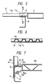
- Fig. 5 is a sectional view taken along line V-V of Fig. 3;
- Fig. 6 is a sectional view taken along line VI-VI of Fig. 5;
- Figs. 7, 8, 9 and 10 are sectional views showing a plurality of other embodiments of the present invention showing joined sections between a side sill and a center underframe;
- Fig. 11 is a sectional view showing a joined section between an end underframe and a center underframe in another embodiment of the car body according to the present invention;
- Fig. 12 is a plan view showing the joined section of the end underframe and the center underframe of Fig. 11;
- Figs. 13, 14, 16 and 17 are sectional views of a plurality of other embodiments of the car body according to the present invention, showing joined sections of the end underframe and the center underframe; and
- Fig. 15 is a sectional view taken along line XV-XV of Fig. 14.
- Hereinafter a plurality of embodiments of the present invention will be described with reference to a plurality of drawings.
- First, one embodiment of a car body of railway rolling stock according to the present invention will be explained with reference to Figs. 1 to 6. In the drawings, an
underframe 1 constitutes the undersurface of the car body. A side framing 40 constitutes both sides of the car body. Aroof framing 60 constitutes an upper surface, or a roof section, of the car body. And an end frame 70 constitutes car body ends in the longitudinal direction of the car body. - The
side framing 40 is made up of such side frames asside posts 41,studs 42,door posts 43,stiffeners 44,rocker rails 45,belt rails 46,window heads 47 andcant rails 48, which are combined and joined through joiningmembers 49, and by joining a sideouter plate 50 on the outside of these side frame members. The side frame members and the sideouter plate 50 are produced of steel for structural use. Theroof framing 60 is constituted by assembling and joining such roof frame members ascant rails 61 andcarlines 62, and also by joining roofouter plate 63 on the outside of these roof frame members. The roofouter plates 63 are stainless steel plates, which have corrugated sections. The roof frame members are produced from stainless steel or steel for structural use. The end framing 70 is constituted by assembling end frame members such as corner posts, end posts, end places and stiffeners and by joining them through joining members and also by joining end outer places to the outside of these end frame members. The end frame members and the end outer places are produced of steel for structural use. The detailed construction of the end framing 70 is not illustrated. - The
underframe 1 is composed of acenter underframe 2 and anend underframe 3. Thecenter underframe 2 is built by parallelly joining a plurality ofextruded shapes 4 of aluminum alloy. Theextruded shapes 4 extend in the longitudinal direction of the car body of the underframe, being parallelly arranged in the direction of width of the car body, on the underframe. Theextruded shape 4 has ahollow part 4a inside, and is formed integral with anequipment attaching rail 4b for supporting various equipment such as control equipment or air-conditioning apparatus on the undersurface. - The
end underframe 3 is composed ofside sills 5,end beams 6,center sills 7, 8, abody bolster 9,cross beams 10 and afloor member 11. The twoside sills 5 extending in the longitudinal direction of the car body are arranged at both ends of the underframe in the direction of width of the car body, these ends being connected by the twoend beams 6. Thebody bolster 9 is located close to the center of the underframe in the longitudinal direction of the car body rather than theend beams 6. This body bolster 9 is disposed correspondingly to the center of the truck. The two center sills 7 are disposed parallelly with theside sills 5 between the end beams 6 located at both ends of the underframe in the longitudinal direction of the car body and the body bolster 9. Each end of these center sills is joined to theend sill 6 and the body bolster 9. A spacing between the two center sills is wide enough to install a coupler therebetween. The twocross beams 10 are disposed parallelly with the body bolsters 6 between the twoside sills 6, with their ends connected to the side sills. The cross beams 10 are arranged close to the center of the underframe in the longitudinal direction of the car body rather than the body bolster 9. Theside sills 5, the end beams 6, thecenter sills 7, 8, the body bolster 9 and the cross beams 10 are produced of steel for structural use or stainless steel. Thefloor member 11 is installed to cover the upper surface of thecenter sills 7, 8, the body bolster 9 and the cross beams 10 which are located between the twoside sills 5. Thefloor member 11 is constituted of akeystone plate 11a produced of steel for structural use or stainless steel. A keystone plate 1b is a joining member for joining thekeystone plate 11a with thecenter underframe 2 and has also a function as a floor member. Thekeystone plates keystone plate 11a in the longitudinal direction of the car body is connected to theend beam 6, while the other end in the longitudinal direction of the car body is mounted on the upper surface of thecross beam 10. One end of thekeystone plate 11b in the longitudinal direction of the car body is connected by welding to the end of thecenter underframe 2 in the longitudinal direction of the car body, and the other end in the longitudinal direction of the car body extends as far as the upper surface of thecross beam 10. Thekeystone plates cross beam 10, being joined byrivets 12 to the upper flange of thecross beam 10. Therivets 12 are joining means, which may be substituted for by for example blind rivets, bolts and nuts, and rivet bonding. - Of a plurality of
extruded shapes 4 constituting the center underframe, theextruded shape 4 located adjacent to theside sill 5 is formed integral with a flange 4c, which is coupled with anupper flange 5a of theside sill 5. The flange 4c and theupper flange 5a are joined byblind rivets 13. The end in the direction of width of the car body of the extrudedshape 4 located adjacent to theside sill 5 and alower flange 5b of theside sill 5 are connected by means of a coupling member 14. The coupling member 14 has a "Z" section. The coupling member 14 and theextruded shape 4 and thelower flange 5b are joined by theblind rivets 13. Ahole 4d is provided in the extrudedshape 4 for the insertion of theblind rivet 13. The coupling member 14 has ahole 14a, which is used for joining by spot welding arocker rail 45 constituting theside framing 40 and theside sill 5 in a position indicated by the arrow W. The blind rivets 13 are joining means, which may be substituted for by for example rivets, bolts and nuts, and rivet bonding. - The coupling member 14 may be produced of any one of steel for structural use, stainless steel, and aluminum alloy. Also the
coupling 24 of steel for structural use or a stainless steel can be directly joined by welding to thelower flange 5b. Further, the coupling member 14 of aluminum alloy can be jointed directly by welding to the lower surface or the side surface of the extrudedshape 4. - The steel for structural use usable for the coupling members 14 described above are for example steel for general structures, steel for weather-proof structures, high-tension steel, and steel for welded structures. Stainless steel includes for example austenitic stainless steel. Also light alloys that can be used are JIS A6063, 6NO1, etc.
- Next, the car body under fabrication will be described. Two
side sills 5, twoend beams 6, two center silts 7, twocenter sills 8, two body bolsters 9, and twocross beams 10 are assembled and joined. Further, thekeystone plate 11a is attached to the upper surfaces of the center sills 7,center sills 8, body bolsters 9 and crossbeams 10, thus completing theend underframe 3. A plurality ofextruded shapes 4 are arranged in the direction of width thereof, being joined to one another by welding. Thereafter, thekeystone plate 11b is joined by welding to the end of the plurality ofextruded shapes 4 in the longitudinal direction, thereby completing thecenter underframe 2. Theend underframe 3 and thecenter underframe 2 are fabricated separately. Thecenter underframe 2 is fitted in a space enclosed by the twoside sills 5 and twocross beams 10 of theend underframe 3. Then, the flange 4c of the extrudedshape 4 and theupper flange 5a of theside sill 5 are connected by theblind rivet 13. A hole is drilled in the overlapped section of thekeystone plate 11a, thekeystone plate 11b and the upper flange of thecross beam 5, and the rivet member is inserted in the hole. Thekeystone plate 11a, thekeystone plate 11b, and the upper flange of thecross beam 5 are connected by the rivet member, thus completing theunderframe 1. Theside framing 40, theroof framing 60, and the end framing 70 are fabricated separately from theunderframe 1. Theunderframe 1, theside framing 40, theroof framing 60 and the end framing 70 thus fabricated are assembled by the following procedure. That is, theside framing 40 is disposed on the upper surface of either end of theunderframe 1 in the direction of width of the car body, and the end framing 70 is disposed on the upper surface of either end of theunderframe 1 in the longitudinal direction of the car body. Joining between theunderframe 1 and theside framing 40, between theunderframe 1 and the end framing 70, and between theside framing 40 and the end framing 70 is done by spot welding. Furthermore, the roof framing 60 is disposed above theside framing 40 and the end framing 70. And then joining between theside framing 40 and theroof framing 60 and between the end framing 70 and the roof framing 60 is effected by spot welding, thus completing the car body. Then, the sideouter plate 50 of theside framing 40 and the end outer plate of the end framing 70 are painted on the surfaces thereof. After the car body has been thus painted, various equipment such as control equipment or air-conditioning apparatus are mounted on theequipment suspension rail 4b of theextruded shapes 4 of theunderframe 1. - As described above, the various kinds of members constituting the car body are made up at least of three kinds of materials, thereby enabling the reduction of weight of the car body more than conventional car bodies of steel for structural use and at a lower material cost than light-alloy car bodies. Namely, constituting the
center underframe 2 of a plurality of light-alloy extruded shapes can build theunderframe 1 of greater rigidity and lighter weight than conventional underframes of steel for structural use that bear the same degree of car-end load. Since theequipment attaching rail 4b is formed integral with eachextruded shape 4, lt ls possible to decrease the number of component parts of theunderframe 1, simplify the construction of the underframe, and decrease the number of fabrication processes of theunderframe 1, thereby enabling cost and weight reduction of the whole car body. Theend underframe 3 is built of a steel for structures or stainless steel of lower price than the light-alloy material. Accordingly, theunderframe 1 can be produced at a lower material cost than the underframe the whole body of which is built of the light-alloy material. Also it is possible to prevent theend underframe 3 from corrosion by producing it of a stainless steel. This constitution will be effective when a lavatory or a toilet is set at the end in the longitudinal direction of the car body. Furthermore, since theside framing 40, roof framing 60 and end framing 70 of the car body of the present invention are produced of an inexpensive steel for structures or a stainless steel, the material cost of the whole car body can be diminished as compared with conventional light-alloy bodies. In addition, the roofouter places 63 are produced of a stainless steel. Because the stainless steel is not liable to corrosion, it is unnecessary to take corrosion prevention into consideration and use thicker roofouter places 63, thereby achieving the reduction of weight of theroof framing 60. - By the way, the weight of the roof framing can be decreased by using fiber-reinforced plastic (FRP) roof outer places.
- Furthermore, the side
outer places 50 of theside framing 40 and the end outer places of the end framing 70 which are produced of steel for structures can be painted without a special surface treatment because of better paintability of the outer places of the steel for structure than the stainless outer places. Therefore, much labour and time are not required for painting theside framing 40 and end framing 70 of the car body. The car body produced of the steel for structural use can fully meet varieties of requirements as to car body design. - In the embodiment of the present invention described above, the
center underframe 2 of theunderframe 1 is produced of a plurality of extruded shapes of aluminum alloy. The weight of the underframe can be reduced more than theunderframe 1 by using many light-alloy cross beams in place of thecenter underframe 2 in parallel with the body bolster 10 between theside sills 5. Further, it is possible to decrease the cost of the underframe and the car body by using, for the end underframe, a steel for structures and a stainless steel of lower cost than the light-alloy material. - The construction of a joining section between the
extruded shapes 4 disposed on both sides in the direction of width of car body of thecenter underframe 2 and theside sills 5 of theend underframe 3 will be explained with reference to Fig. 4. With the joining flange 4c set on theupper flange 5a, the flange 4c is joined to theupper flange 5a by theblind rivets 13, thus joining theextruded shape 4 to theside sill 5. Also, The end section in the direction of width of the extrudedshape 4 is connected to thelower flange 5b by the coupling member 14, thus connecting theextruded shape 4 to theside sill 5. Accordingly the joining section of the extrudedshape 4 and theside sill 5 has a box-like sectional form having improved rigidity and durability. However, because of the box-like sectional form of the joining section of the extrudedshape 4 and theside sill 5, it is likely that rain water will accumulate therein. It is, therefore, desirable to make theside sills 5 and the coupling member of stainless steel. It is also desirable to provide the side sill with a water drain hole where there is the possibility of water accumulation in the joining section between theextruded section 4 and theside sill 5 as described above. Joining between theunderframe 1 and theside framing 40, that is, joining between the sideouter plate 50 and therocker rail 45 and theside sill 5 are effected by spot welding. Plug welding is performed in a joining section, or a body bolster mounting position, between theunderframe 1 and theside framing 40, where the spot welding electrode can not be inserted. Since theunderframe 1 and theside framing 40 are joined principally by spot welding as described above, joining workability can be improved. It is also possible to lessen distortion occurring in theside framing 40, particularly in the side outer places 50. - Next, the construction of a joining section of the end of the
center underframe 2 in the longitudinal direction of the car body and thecross beam 10 of theend underframe 3 and thefloor member 11 will be explained with reference to Figs. 5 and 6. Thecross beam 10 and thekeystone plate 11a are connected to the center underframe through thekeystone plate 11b. Accordingly the car-end load acting on one coupler of theunderframe 1 passes to thecenter underframe 2 through the center sill 7, the body bolster 9, thecenter sill 8 and thecross beam 10 or through the center sill 7, the body bolster 9 and thekeystone plate 11a, and then via thekeystone plate 11b. Namely, in theunderframe 1, the car-end load acting on one coupler of the underframe is transmitted to the other coupler of the underframe not only along theside sill 5 but along thecenter underframe 2, thereby enabling the reduction of the car-body load theside sill 5 bears and a decrease in the plate thickness and weight of theside sill 5 itself. - In the
underframe 1, the end underframe having the body bolster 9 which transmits the vertical load of the whole car body to the truck is produced of the steel for structural use as described above. Since theunderframe 1 is built of high-rigidity material as compared with the underframe the whole body of which is produced of a light-alloy material, the body bolster itself and its surrounding construction can be simplified. - Next, other embodiments of the car body of railway rolling stock according to the present invention will be described with reference to Figs. 7 to 10. These drawings give the construction of the car body of railway rolling stock according to other embodiments of the present invention, showing the joining section of the center underframe and the side sill.
- First, the embodiment shown in Fig. 7 differs from the first embodiment previously described, in the construction of the extruded
shape 104 equivalent to the extrudedshape 4 used in the first embodiment and the construction of thecoupling member 114 equivalent to the coupling member 14 in the first, embodiment. In Fig. 7, the same reference numerals as those used in the first embodiment denote the same members as those illustrated in the first embodiment. Theextruded shape 104 is formed integral with a joiningflange 104e extending towards the web of theside sill 5, in a lower position where the extrudedshape 104 comes in contact with theside sill 5. Theflange 104e extends obliquely downwardly. Theextruded shape 104 has a similar construction as theextruded shape 4 of the first embodiment except for the joiningflange 104e. Theflange 104e has ahole 104f formed for a blind rivet. Thecoupling member 114 is formed nearly in the L section. Thecoupling section 114 is arranged such that one flat section will overlap with the inner surface of the web of theside sill 5, while the other flat section will overlap the joiningflange 104e. Thecoupling member 114 and theflange 104e are joined by theblind rivet 13 at their overlap section. Thecoupling member 114 and thecross beam 5 are joined by spot welding at their overlap. The joining of thecoupling member 114 to thecross beam 5 is done together with spot-welding therocker rail 45, the sideouter plate 50 and theside sill 5. When the center underframe is constituted of the extruded shapes 104, it is difficult to separately fabricate the center underframe and the end underframe. Namely, since the extrudedshape 104 has the joiningflange 104e, a center underframe completed by joining with other extruded shapes can not be inserted in between theside sills 5 of the end underframe. Therefore when the center underframe is constituted of the extruded shapes 104, it is necessary to install a plurality of extruded shapes simultaneously when building the end underframe. - According to such a constitution, the joining section between the
side sill 5 and theextruded shape 104 can be built into a box-like section, thus improving the rigidity of the joining section. Furthermore, since spot welding for joining theside sill 5 with theside framing 40 can be done without using an access hole, workability can be improved. Also, since a spot-welded part can directly visually be checked, the reliability of the joining section between theside sill 5 and theside framing 40 can be improved. Further it is possible to prevent the entrance of rain water into the joining section by closing thehole 104f after completing the joining between theside sill 5 and theside framing 40. The construction according to the present embodiment is effective particularly when using theside sills 5 produced from steel for structural purposes. - The embodiment shown in Fig. 8 differs in the construction of the extruded
shape 204 equivalent to the extrudedshape 4 in the first embodiment and in the construction of theside sill 205 equivalent to the side sill appearing in the first embodiment. ln Fig. 8, the same reference numerals as those used in the first embodiment denote the same members as those appearing in the first embodiment. The end face of the extrudedshape 204 which comes in contact with theside sill 5 is formed perpendicular to theside sill 5. That is, theextruded shape 204 is not provided with the joiningflange 4c, 104e. Theside sill 205 has a joiningsection 205c formed for joining with theextruded shape 204 by projecting the web section toward the center side in the direction of width of the underframe. The joiningsection 205c is formed by bending a material for constituting theside sill 205. For forming the joiningsection 205c, a conceivable method is to attach members forming the joiningsection 205c to the web of theside sill 205 by welding. The joiningsection 205c is joined by theblind rivet 13 to the end face of a part of the extrudedshape 204 which comes in contact with theside silt 5. Theextruded shape 204 has, a hole 205d for theblind rivet 13. Theside framing 40 and theside sill 205 are joined by spot welding at the position indicated by the arrow W. Namely, theside sill 205 has a vertical web formed for spot welding. - The
side sill 205, having the joiningsection 205c on the web, has greater rigidity than the upper flange of the side sill. According to this embodiment, therefore, it is possible to improve the strength of the whole body of the underframe. Also according to this embodiment, it is unnecessary to join the extruded shape with the side sill by the coupling member as in the first embodiment. Further, the rigidity of theside sill 205 itself can be improved by forming the joiningsection 205c on theside sill 205. According to this embodiment, the end underframe and the center underframe, which are fabricated separately, can be jointed with ease. The center underframe constituted of the extrudedshapes 204 can be inserted in between theside sills 205 installed between both aides of the end underframe in the direction of width, in either upward or downward direction of the end underframe. Furthermore, according to the present embodiment, the positional relation between the upper surface of theside sill 205 and the upper surface of the center underframe constituted of the extrudedshapes 204 can be adjusted in the perpendicular direction. - In the embodiment shown in Fig. 9, the construction of the
side sill 305 equivalent to the side sill of the first embodiment differs from the first embodiment. In Fig. 9, the same reference numerals as those used in the first embodiment denote the same members as those appearing in the first embodiment. On theupper flange 305a of theside sill 305 is formed arib 305d at the end section on the central side of theupper flange 305a in the direction of width of the underframe. Thisrib 305d is formed in parallel with the web of theside sill 305 by bending the forward end section of theupper flange 305a. - According to this embodiment, the
upper flange 305d can be improved in rigidity by forming arib 305d thereon. Therefore, in the construction that thecenter underframe 4 and theside sill 305 are joined through the flange 4c, theupper flange 305a can be prevented from deformation. Therib 305d can be formed by bending the forward end of theupper flange 305a and therefore can easily be fabricated, theside sill 305 itself being of simple construction. - In the embodiment shown in Fig. 10, the construction of the
side sill 405 equivalent to the side sill of the first embodiment differs from that of the first embodiment. In Fig. 10, the same reference numerals used in the first embodiment denote the same members in the first embodiment. The extruded shapes of the present embodiment are nearly of the similar constitution as the extruded shapes shown in Fig. 8. Theside sill 405 is provided with asupport section 405e which supports the L-sectioned center underframe at the forward end section of theupper flange 405. Thesupport section 405e supports the center underframe in the state that the upper surface of thecenter section 405e is flush with the upper surface of theside sill 405. Thesupport section 405e and thecenter underframe 204 are joined by theblind rivet 13. The hale 204e is for mounting theblind rivet 13. When a blind rivet capable of joining thesupport section 405e to thecenter underframe 204 from one side is used in place of the aforementionedblind rivet 13, it is unnecessary to make thehole 204e in thecenter underframe 204. - According to this embodiment, the rigidity of the
side sill 405 itself can be improved by forming thesupport section 405e on theside sill 405. Also it is possible to set the upper surface of thecenter underframe 204 flush with the upper surface of theside silt 405 simply by mounting thecenter underframe 204 on thesupport section 405e, thereby improving operation efficiency in fabricating the underframe. - Next, another embodiment of the car body of railway rolling stock according to the present invention will be explained with reference to Figs. 11 to 17. Figs. 11 to 17 show the construction of the joining section of the floor member and cross beam of the end under frame and the center underframe of the car body of railway rolling stock according to another embodiment of the present invention.
- The embodiments shown in Figs. 11 and 12 differs from the first embodiment in the construction of the joining
members 20a and 20b and in the construction of thekeystone plate 11a. In Figs. 11 and 12, the same reference numerals as those used in the first embodiment denote the same members appearing in the first embodiment. Thecenter underframe 102 has basically the identical constitution as thecenter underframe 2 of the first embodiment. At the end of thecenter underframe 102 in the longitudinal direction of the car body is joined the joining member 20a. This joining member 20a, produced of aluminum alloy, has a nearly T-form section and is welded to thecenter underframe 102 by welding. To the web of thecross beam 10 is joined the joiningmember 20b. This joiningmember 20b has a nearly L-shaped section and constituted of steel for structural use or stainless steel. The joiningmember 20b is joined to thecross beam 10 by welding, and has a function to support thecenter underframe 102 in relation to thecross beam 10, that is, a function as a support member. The end section of thekeystone plate 11a on the center section side of the underframe in the longitudinal direction of the car body is extending to a position close to thecenter underframe 102 rather than thecross beam 10. Thekeystone plate 11a is overlapped vertically with the joiningmembers 20a and 20b. On the upper surface of thekeystone plate 11a is installed apatch 21 correspondingly to these overlapped sections, and aspacer 22 is installed between thekeystone plate 11a and the joining member 20a. Thepatch 21, thekeystone plate 11a, thespacer 22, the joining member 20a and joiningmember 20b are vertically overlappingly installed and joined all together by means of theblind rivet 13. An increased number of theblind rivets 13 are used near thecenter sill 8 as shown in Fig. 12. Thus increasing the number of theblind rivets 13 facilitates the passage of the car-end load from thecenter sill 8 to thecenter underframe 102 or from thecenter underframe 102 to thecenter sill 8. Between the end section of thekeystone plate 11a on the center side of the underframe in the longitudinal direction of the carbody and the joining member 20a is filled a filling-upmaterial 23. For the filling-upmaterial 23, a polyurethane resin for example is used. - According to the present embodiment, since the joining member 20a is installed between the
keystone plate 11a and the joiningmember 20b, no moment will unnecessarily act on these joining sections. Therefore, if a great car-end load acts among the joining member 20a, thekeystone plate 11a and the joiningmember 20b, these joining sections will not be subjected to deformation, thus providing a greater strength. Also, since a great car-end load can be transmitted among thecenter underframe 102, thekeystone plate 11a and thecross beam 10, the car body load acting on the side sill can be decreased, and accordingly it is possible to decrease the plate thickness of the cross beam, thereby reducing the weight of the cross beam itself. - Next, Fig. 13 shows the construction of the joining section among the
center underframe 202, thekeystone plate 11a and thecross beam 10, which is different from that of the first embodiment. In Fig. 13, the same reference numerals used in the first embodiment denote the same members in the first embodiment. Asupport member 24 is attached to the web of thecross beam 10, supporting the end of thecenter underframe 202 in the longitudinal direction of the car body. Thesupport member 24 and the end section of thecenter underframe 202 in the longitudinal direction are joined by theblind rivet 13. Thekeystone plate 11a and thecross beam 10 are joined by means of theblind rivet 13. Thecenter underframe 202 has acover plate 26 attached at the end face in the longitudinal direction of the car body. Thekeystone plate 11a has acover plate 25, which is attached at the end face in the longitudinal direction of the car body. Between thecover plate 25 and thecover plate 26 is filled a filling-upmaterial 23. This filling-upmaterial 23 in a set state has strength great enough to transmit the car-end load between the end underframe and thecenter underframe 202. - According to the present embodiment, the joining section of the end underframe and the
center underframe 202 is of a simple construction, thereby enabling easy fabrication of the underframe. Between the end underframe and thecenter underframe 202 is filled the filling-upmaterial 23, and therefore any dimensional error, if present between these underframes, can easily be permitted. Further, the car-end load can be exactly transmitted through the filling-upmaterial 23 between the end underframe and thecenter underframe 202. - The embodiment shown in Figs. 14 and 15 differs from the first embodiment in the construction of the joining
member 27 and the construction of the joining section among the joiningmember 27, thekeystone plate 11a and thecenter underframe 202. In these drawings, the same reference numerals used in the first embodiment denote the same members appearing in the first embodiment. The joiningmember 27 is a clad member made by joining analuminum alloy plate 27a and aplate 27 of stainless steel or steel for structural use by explosive bonding. The joiningmember 27 is made by inserting abrazing sheet 27c in between theplate 27a and theplate 27b and joining them by explosive bonding them together. This joiningmember 27 is produced by joining theplaces keystone plate 11a. The joiningmember 27 has both an overlapping part and a nonoverlapping part between theplate 27a and theplate 27b. The nonoverlapping part is joined by welding to thekeystone plate 11a and thecenter underframe 202. Namely, the nonoverlapping part between theplate 27a and theplate 27b is joined to thecenter underframe 202 by welding. Also, a nonoverlapping part between theplate 27b and theplate 27a is joined to thekeystone plate 11a by welding. - According to the present embodiment, the joining
member 27 can easily be joined by welding thekeystone plate 11a to thecenter underframe 202. Therefore, according to this embodiment, the end underframe and thecenter underframe 202 can be joined relatively easily by welding. Further, according to this embodiment, labour and time required in fabricating the underframe can be reduced. - Next, Fig. 16 shows the construction of the
center underframe 302 and thekeystone plate 111a, which differs from that of the first embodiment. In Fig. 16, the same reference numerals as those used in the first embodiment denote the same members appearing in the first embodiment. Thecenter underframe 302 has acutout 302a at the end section in the longitudinal direction of the car body. The vertical size of thecutout 302a coincides with that of thekeystone plate 111a. That is, when the end of thekeystone plate 111a in the longitudinal direction of the car body is set in thecutout 302a, the upper surface of thecenter underframe 302 is flush with the upper surface of thekeystone plate 111a. Thecutout 302a is fitted with acover plate 26. The end section of thekeystone plate 111a in the longitudinal direction of the car body protrudes out towards the center underframe 30. Namely, thekeystone plate 111a is longer in the longitudinal direction of the car body than thekeystone plate 11a of the first embodiment. At the end of thekeystone plate 111a in the longitudinal direction of the car body, acover plate 25 is attached. Between thecover plate 25 and thecover plate 26 is filled the filling-upmaterial 23. The end of thecenter underframe 302 in the longitudinal direction of the car body is connected to thecross beam 10 through thesupport member 24. Thecenter underframe 302 and thesupport member 24 are joined by theblind rivet 13. - According to the present embodiment, because of little amount of filling-up
material 23 in addition to a similar effect as each of the embodiments described above, a car-end compression is exactly transmitted. Filling the filling-upmaterial 23 permits a dimensional error of each member and also improves the airtightness of the car body. - Next, Fig. 17 shows the construction of the
cross beam 110, which differs from the first embodiment. In Fig. 16, the same reference numerals as those used in the first embodiment represent the same members as those appearing in the first embodiment. Thecross beam 110 is made with theupper flange 110a extended toward the center side of the underframe in the longitudinal direction of the car body. Theupper flange 110a has a nearly Z-sectional form, supporting the end of thecenter underframe 202 in the longitudinal direction of the car body. Theupper flange 110a is joined to the end of thecenter underframe 202 in the longitudinal direction of the car body by theblind rivet 13. Theblind rivet 13 can be inserted from under the lower surface side of theupper flange 110a. Thekeystone plate 11a and thecenter underframe 202 are fitted with the cover places 25 and 26 at their end sections as viewed in the longitudinal direction of the car body. Between thecover plate 25 of thekeystone plate 11a and thecover plate 26 of the center underframe is filled the filling-upmaterial 23. - According to the present embodiment, since the
upper flange 110a supporting thecenter underframe 202 is formed integral with thecross beam 110, the number of component parts of the underframe can be decreased. Also according to this embodiment, the joining of the end underframe with thecenter underframe 202 is completed by joining theupper flange 110a with thecenter underframe 202 after placing thecenter underframe 202 on the upper surface of theupper flange 110a. Therefore, joining the end underframe with thecenter underframe 202 can easily be performed. In the embodiment described above, the support section of thecenter underframe 202 is formed integral with thecross beam 110, but a part corresponding to theupper flange 110a or the support section of thecenter underframe 202 may be constituted of other members and joined by welding to the cross beam. - In each of the embodiments described above, an example of the end underframe built of steel for structures or stainless steel has been explained. However, it is possible to build the end underframe of a material of high yield strength such as a high-tension steel. Further, the rigidity of the whole body of the underframe can be improved by building the end underframe of the high-tension steel, resulting in a decreased plate thickness of various component members of the underframe and accordingly in the decreased weight of the whole body of the underframe.
- According to the present invention, it is possible to provide a car body of railway rolling stock capable of minimizing the material cost of the whole car body and facilitating the mounting of various equipment on the undersurface of the underframe.
- According to the present invention, it is also possible to provide a car body of railway rolling stock which, in addition to the above-mentioned effect, has an effect to prevent the occurrence of a trouble likely to be caused by corrosion.
- Further according to the present invention, it is possible to provide a car body of railway rolling stock which, in addition to a plurality of effects described above, has an effect to facilitate painting of at least side surfaces of the car body.
Claims (16)
Applications Claiming Priority (2)
| Application Number | Priority Date | Filing Date | Title |
|---|---|---|---|
| JP9287689 | 1989-04-14 | ||
| JP92876/89 | 1989-04-14 |
Publications (3)
| Publication Number | Publication Date |
|---|---|
| EP0392828A2 true EP0392828A2 (en) | 1990-10-17 |
| EP0392828A3 EP0392828A3 (en) | 1991-10-30 |
| EP0392828B1 EP0392828B1 (en) | 1995-07-26 |
Family
ID=14066649
Family Applications (1)
| Application Number | Title | Priority Date | Filing Date |
|---|---|---|---|
| EP90303922A Expired - Lifetime EP0392828B1 (en) | 1989-04-14 | 1990-04-11 | Railway car body and its method of manufacture |
Country Status (4)
| Country | Link |
|---|---|
| EP (1) | EP0392828B1 (en) |
| KR (1) | KR900015997A (en) |
| DE (1) | DE69021113T2 (en) |
| ES (1) | ES2076308T3 (en) |
Cited By (13)
| Publication number | Priority date | Publication date | Assignee | Title |
|---|---|---|---|---|
| DE4218751A1 (en) * | 1992-06-03 | 1993-12-09 | Goerlitz Waggonbau Gmbh | Body structure for rail vehicles, in particular passenger coaches |
| US5279230A (en) * | 1992-11-24 | 1994-01-18 | Gunderson, Inc. | Railroad well car body |
| EP0618124A1 (en) * | 1993-03-29 | 1994-10-05 | A.N.F. Industrie | Structure of a railway body having shell sections |
| US5611285A (en) * | 1992-11-24 | 1997-03-18 | Gunderson, Inc. | Multipurpose railraod well car |
| DE19649041A1 (en) * | 1996-11-27 | 1998-05-28 | Duewag Ag | Car body of a rail vehicle |
| WO2001036245A1 (en) * | 1999-11-17 | 2001-05-25 | Siemens Sgp Verkehrstechnik Gmbh | Aluminum large-profile main stretcher for rail vehicles |
| EP1832491A2 (en) * | 2006-03-06 | 2007-09-12 | Siemens Transportation Systems GmbH & Co KG | Rail vehicle with an underframe |
| EP2689986A1 (en) * | 2011-03-23 | 2014-01-29 | Kawasaki Jukogyo Kabushiki Kaisha | Railway car comprising heat-resistant floor |
| WO2016135092A1 (en) | 2015-02-24 | 2016-09-01 | Airbus Defence And Space Sas | Composite panel provided with an improved assembly end piece and structure comprising such a panel |
| EP3315377A1 (en) * | 2016-10-27 | 2018-05-02 | ALSTOM Transport Technologies | Bodywork structure for a vehicle on rails and method for manufacturing such a bodywork structure |
| CN111891156A (en) * | 2020-08-28 | 2020-11-06 | 中车戚墅堰机车有限公司 | Novel corridor body structure in diesel locomotive |
| CN112477893A (en) * | 2020-12-11 | 2021-03-12 | 交控科技股份有限公司 | Railway vehicle carriage and railway vehicle |
| CN113479226A (en) * | 2021-02-07 | 2021-10-08 | 常州市新创智能科技有限公司 | Carbon fiber composite material underframe structure of high-speed rail transit motor train unit body |
Citations (3)
| Publication number | Priority date | Publication date | Assignee | Title |
|---|---|---|---|---|
| BE508069A (en) * | ||||
| DE3309736A1 (en) * | 1983-03-18 | 1984-09-27 | M.A.N. Maschinenfabrik Augsburg-Nürnberg AG, 8500 Nürnberg | Underframe for wagon bodies of rail vehicles |
| FR2630698A1 (en) * | 1988-04-29 | 1989-11-03 | Dietrich & Cie De | Railway carriage structure made of steel and aluminium with welded connections |
-
1990
- 1990-04-11 DE DE69021113T patent/DE69021113T2/en not_active Expired - Fee Related
- 1990-04-11 EP EP90303922A patent/EP0392828B1/en not_active Expired - Lifetime
- 1990-04-11 ES ES90303922T patent/ES2076308T3/en not_active Expired - Lifetime
- 1990-04-14 KR KR1019900005191A patent/KR900015997A/en not_active Application Discontinuation
Patent Citations (3)
| Publication number | Priority date | Publication date | Assignee | Title |
|---|---|---|---|---|
| BE508069A (en) * | ||||
| DE3309736A1 (en) * | 1983-03-18 | 1984-09-27 | M.A.N. Maschinenfabrik Augsburg-Nürnberg AG, 8500 Nürnberg | Underframe for wagon bodies of rail vehicles |
| FR2630698A1 (en) * | 1988-04-29 | 1989-11-03 | Dietrich & Cie De | Railway carriage structure made of steel and aluminium with welded connections |
Cited By (21)
| Publication number | Priority date | Publication date | Assignee | Title |
|---|---|---|---|---|
| DE4218751A1 (en) * | 1992-06-03 | 1993-12-09 | Goerlitz Waggonbau Gmbh | Body structure for rail vehicles, in particular passenger coaches |
| US5279230A (en) * | 1992-11-24 | 1994-01-18 | Gunderson, Inc. | Railroad well car body |
| US5611285A (en) * | 1992-11-24 | 1997-03-18 | Gunderson, Inc. | Multipurpose railraod well car |
| EP0618124A1 (en) * | 1993-03-29 | 1994-10-05 | A.N.F. Industrie | Structure of a railway body having shell sections |
| FR2703316A1 (en) * | 1993-03-29 | 1994-10-07 | Anf Ind | Railway equipment body with hull profile structure. |
| DE19649041A1 (en) * | 1996-11-27 | 1998-05-28 | Duewag Ag | Car body of a rail vehicle |
| WO2001036245A1 (en) * | 1999-11-17 | 2001-05-25 | Siemens Sgp Verkehrstechnik Gmbh | Aluminum large-profile main stretcher for rail vehicles |
| EP1832491A2 (en) * | 2006-03-06 | 2007-09-12 | Siemens Transportation Systems GmbH & Co KG | Rail vehicle with an underframe |
| EP1832491A3 (en) * | 2006-03-06 | 2011-03-23 | Siemens AG Österreich | Rail vehicle with an underframe |
| EP2689986A4 (en) * | 2011-03-23 | 2015-01-28 | Kawasaki Heavy Ind Ltd | Railway car comprising heat-resistant floor |
| EP2689986A1 (en) * | 2011-03-23 | 2014-01-29 | Kawasaki Jukogyo Kabushiki Kaisha | Railway car comprising heat-resistant floor |
| US9233694B2 (en) | 2011-03-23 | 2016-01-12 | Kawasaki Jukogyo Kabushiki Kaisha | Railcar including heat-resistant floor |
| WO2016135092A1 (en) | 2015-02-24 | 2016-09-01 | Airbus Defence And Space Sas | Composite panel provided with an improved assembly end piece and structure comprising such a panel |
| EP3315377A1 (en) * | 2016-10-27 | 2018-05-02 | ALSTOM Transport Technologies | Bodywork structure for a vehicle on rails and method for manufacturing such a bodywork structure |
| FR3058119A1 (en) * | 2016-10-27 | 2018-05-04 | Alstom Transport Technologies | BODY STRUCTURE FOR A VEHICLE ON RAILS AND METHOD FOR MANUFACTURING SUCH A BODY STRUCTURE |
| US10703390B2 (en) | 2016-10-27 | 2020-07-07 | Alstom Transport Technologies | Railway vehicle body structure and manufacturing process thereof |
| RU2743830C2 (en) * | 2016-10-27 | 2021-02-26 | Альстом Транспорт Текнолоджис | Box structure of a rail vehicle and method for its manufacture |
| CN111891156A (en) * | 2020-08-28 | 2020-11-06 | 中车戚墅堰机车有限公司 | Novel corridor body structure in diesel locomotive |
| CN111891156B (en) * | 2020-08-28 | 2024-03-29 | 中车戚墅堰机车有限公司 | Corridor vehicle body structure in novel diesel locomotive |
| CN112477893A (en) * | 2020-12-11 | 2021-03-12 | 交控科技股份有限公司 | Railway vehicle carriage and railway vehicle |
| CN113479226A (en) * | 2021-02-07 | 2021-10-08 | 常州市新创智能科技有限公司 | Carbon fiber composite material underframe structure of high-speed rail transit motor train unit body |
Also Published As
| Publication number | Publication date |
|---|---|
| ES2076308T3 (en) | 1995-11-01 |
| DE69021113T2 (en) | 1996-04-04 |
| DE69021113D1 (en) | 1995-08-31 |
| EP0392828A3 (en) | 1991-10-30 |
| EP0392828B1 (en) | 1995-07-26 |
| KR900015997A (en) | 1990-11-12 |
Similar Documents
| Publication | Publication Date | Title |
|---|---|---|
| EP0405889B1 (en) | Railway car body structures and methods of making them | |
| EP0392828B1 (en) | Railway car body and its method of manufacture | |
| US4966082A (en) | Construction and a manufacturing method of underframe for a rolling stock | |
| US6065261A (en) | Construction using extruded sections and composite panels | |
| US5287814A (en) | Car body of railway rolling stock and method for fabricating car body | |
| US5784970A (en) | Carriage body frame | |
| KR960008197B1 (en) | Railway car body structures | |
| EP0672567A1 (en) | Railway vehicle bodies and methods of manufacturing them | |
| US5199632A (en) | Railway car body structures and methods of making them | |
| KR0154132B1 (en) | Railway car body structures and method of making them | |
| EP0544498B1 (en) | Body structure of railroad car | |
| US4645258A (en) | Underframe construction for railway vehicle | |
| EP0697319A1 (en) | Car body for a railway rolling stock | |
| JP4731283B2 (en) | Railway vehicle body structure | |
| US3461819A (en) | Vehicle body construction and method of making it | |
| JP2626340B2 (en) | Vehicle underframe | |
| WO2013077192A1 (en) | Vehicle traveling on track | |
| JPH06183340A (en) | Rolling stock body structure | |
| JPH0350063A (en) | Body for rolling stock and manufacture thereof | |
| JP2675183B2 (en) | Car body | |
| JP2894313B2 (en) | Car body | |
| JP2003523885A (en) | Flat element and method of manufacturing flat element | |
| US4353314A (en) | Box car corner post arrangement | |
| CN113306586B (en) | Roof side beam, roof and railway vehicle | |
| JP5466114B2 (en) | Railway vehicle structure |
Legal Events
| Date | Code | Title | Description |
|---|---|---|---|
| PUAI | Public reference made under article 153(3) epc to a published international application that has entered the european phase |
Free format text: ORIGINAL CODE: 0009012 |
|
| AK | Designated contracting states |
Kind code of ref document: A2 Designated state(s): DE ES FR GB IT |
|
| PUAL | Search report despatched |
Free format text: ORIGINAL CODE: 0009013 |
|
| AK | Designated contracting states |
Kind code of ref document: A3 Designated state(s): DE ES FR GB IT |
|
| 17P | Request for examination filed |
Effective date: 19920227 |
|
| 17Q | First examination report despatched |
Effective date: 19931125 |
|
| GRAA | (expected) grant |
Free format text: ORIGINAL CODE: 0009210 |
|
| AK | Designated contracting states |
Kind code of ref document: B1 Designated state(s): DE ES FR GB IT |
|
| REF | Corresponds to: |
Ref document number: 69021113 Country of ref document: DE Date of ref document: 19950831 |
|
| ITF | It: translation for a ep patent filed |
Owner name: MODIANO & ASSOCIATI S.R.L. |
|
| REG | Reference to a national code |
Ref country code: ES Ref legal event code: FG2A Ref document number: 2076308 Country of ref document: ES Kind code of ref document: T3 |
|
| ET | Fr: translation filed | ||
| PLBE | No opposition filed within time limit |
Free format text: ORIGINAL CODE: 0009261 |
|
| STAA | Information on the status of an ep patent application or granted ep patent |
Free format text: STATUS: NO OPPOSITION FILED WITHIN TIME LIMIT |
|
| 26N | No opposition filed | ||
| PGFP | Annual fee paid to national office [announced via postgrant information from national office to epo] |
Ref country code: GB Payment date: 19970401 Year of fee payment: 8 |
|
| PGFP | Annual fee paid to national office [announced via postgrant information from national office to epo] |
Ref country code: FR Payment date: 19970418 Year of fee payment: 8 |
|
| PGFP | Annual fee paid to national office [announced via postgrant information from national office to epo] |
Ref country code: ES Payment date: 19970425 Year of fee payment: 8 |
|
| PGFP | Annual fee paid to national office [announced via postgrant information from national office to epo] |
Ref country code: DE Payment date: 19970626 Year of fee payment: 8 |
|
| PG25 | Lapsed in a contracting state [announced via postgrant information from national office to epo] |
Ref country code: GB Free format text: LAPSE BECAUSE OF NON-PAYMENT OF DUE FEES Effective date: 19980411 |
|
| PG25 | Lapsed in a contracting state [announced via postgrant information from national office to epo] |
Ref country code: ES Free format text: LAPSE BECAUSE OF NON-PAYMENT OF DUE FEES Effective date: 19980413 |
|
| PG25 | Lapsed in a contracting state [announced via postgrant information from national office to epo] |
Ref country code: FR Free format text: THE PATENT HAS BEEN ANNULLED BY A DECISION OF A NATIONAL AUTHORITY Effective date: 19980430 |
|
| GBPC | Gb: european patent ceased through non-payment of renewal fee |
Effective date: 19980411 |
|
| PG25 | Lapsed in a contracting state [announced via postgrant information from national office to epo] |
Ref country code: DE Free format text: LAPSE BECAUSE OF NON-PAYMENT OF DUE FEES Effective date: 19990202 |
|
| REG | Reference to a national code |
Ref country code: FR Ref legal event code: ST |
|
| REG | Reference to a national code |
Ref country code: ES Ref legal event code: FD2A Effective date: 20000503 |
|
| PG25 | Lapsed in a contracting state [announced via postgrant information from national office to epo] |
Ref country code: IT Free format text: LAPSE BECAUSE OF NON-PAYMENT OF DUE FEES;WARNING: LAPSES OF ITALIAN PATENTS WITH EFFECTIVE DATE BEFORE 2007 MAY HAVE OCCURRED AT ANY TIME BEFORE 2007. THE CORRECT EFFECTIVE DATE MAY BE DIFFERENT FROM THE ONE RECORDED. Effective date: 20050411 |