EP0390427B1 - Nozzle drive control system and method for ink jet printing - Google Patents
Nozzle drive control system and method for ink jet printing Download PDFInfo
- Publication number
- EP0390427B1 EP0390427B1 EP19900303101 EP90303101A EP0390427B1 EP 0390427 B1 EP0390427 B1 EP 0390427B1 EP 19900303101 EP19900303101 EP 19900303101 EP 90303101 A EP90303101 A EP 90303101A EP 0390427 B1 EP0390427 B1 EP 0390427B1
- Authority
- EP
- European Patent Office
- Prior art keywords
- droplets
- value
- detecting
- nozzle
- ink
- Prior art date
- Legal status (The legal status is an assumption and is not a legal conclusion. Google has not performed a legal analysis and makes no representation as to the accuracy of the status listed.)
- Expired - Lifetime
Links
Images

Classifications
-
- B—PERFORMING OPERATIONS; TRANSPORTING
- B41—PRINTING; LINING MACHINES; TYPEWRITERS; STAMPS
- B41J—TYPEWRITERS; SELECTIVE PRINTING MECHANISMS, i.e. MECHANISMS PRINTING OTHERWISE THAN FROM A FORME; CORRECTION OF TYPOGRAPHICAL ERRORS
- B41J2/00—Typewriters or selective printing mechanisms characterised by the printing or marking process for which they are designed
- B41J2/005—Typewriters or selective printing mechanisms characterised by the printing or marking process for which they are designed characterised by bringing liquid or particles selectively into contact with a printing material
- B41J2/01—Ink jet
- B41J2/015—Ink jet characterised by the jet generation process
- B41J2/02—Ink jet characterised by the jet generation process generating a continuous ink jet
-
- B—PERFORMING OPERATIONS; TRANSPORTING
- B41—PRINTING; LINING MACHINES; TYPEWRITERS; STAMPS
- B41J—TYPEWRITERS; SELECTIVE PRINTING MECHANISMS, i.e. MECHANISMS PRINTING OTHERWISE THAN FROM A FORME; CORRECTION OF TYPOGRAPHICAL ERRORS
- B41J2/00—Typewriters or selective printing mechanisms characterised by the printing or marking process for which they are designed
- B41J2/005—Typewriters or selective printing mechanisms characterised by the printing or marking process for which they are designed characterised by bringing liquid or particles selectively into contact with a printing material
- B41J2/01—Ink jet
- B41J2/07—Ink jet characterised by jet control
- B41J2/12—Ink jet characterised by jet control testing or correcting charge or deflection
Definitions
- This invention relates to ink jet printing systems and similar drop marking systems in which a supply of electrically conductive ink is provided to a nozzle.
- the ink is forced through a nozzle orifice while at the same time an exciting voltage is applied to the nozzle to cause the stream of ink to break into droplets which can be charged and deflected onto a substrate to be marked.
- Such ink jet technology is well known and, for example, see U.S. Patent Nos. 4,727,379 and 4,555,712.
- the exciting energy or voltage applied to the nozzle must be properly set during operation of the system.
- most ink jet printers require manual setting of the energy applied to the ink stream as it exits the nozzle.
- the appropriate value is either empirically determined by comparing what is seen to an existing diagram or by determining the drop separation point and comparing it with machine specifications. In either case, the resulting print quality varies.
- a system control microprocessor receives the digital ink jet current signal from the electrometer and is programmed to control the gain of a stimulation amplifier, of which the output is applied to the piezoelectric transducer on the ink jet printing head, by providing a reference signal to an automatic gain control circuit.
- the stimulation amplitude is initially adjusted to a low level to allow the length of the ink filament to approach its natural unstimulated length.
- the stimulation amplitude is then monotonically increased whilst the charge imparted to the ink jet is monitored by the electrometer.
- the ink filament becomes shorter and the ink drop separation approaches the narrow charging electrode. In this manner the ink jet current registered by the electrometer provides a signal that is proportional to the length of the ink filament.
- the system control microprocessor is used to increase the stimulation reference signal in increments whilst monitoring the jet current signal provided by the electrometer.
- the jet current signal is recorded and a peak is detected representing the entry into overdrive, that is a region of stimulation above the minimum filament length in which satellite drops are produced and drop deflection is stated as being difficult to control.
- the stimulation amplitude is then set at some predetermined point below the peak that is found to provide reliable stimulation by computing the reference level as a function of the reference level at the peak. It is suggested that the reference level may be set to the stimulation amplitude at the peak minus 25mV, that is a constant offset from the stimulation amplitude at peak.
- U.S. Patent No. 4,638,325 accordingly teaches that the stimulation amplitude applied to the nozzle of an ink jet printer may be set by a control circuit which includes detecting means (in the form of a piezoelectric feedback transducer) for determining the value of the stimulation amplitude as its magnitude is slowly increased from a minimum value and for detecting the value of the stimulation amplitude at which droplet formation occurs closest to the nozzle (that is the peak representing entry into overdrive).
- detecting means in the form of a piezoelectric feedback transducer
- What is desired is a system which can determine a range of proper printing nozzle drive voltages and then compute a satisfactory intermediate value within said range.
- Such a system should be temperature independent over a wide range of operating temperatures to result in a significantly better control system.
- a detecting means is arranged to detect the value C(L) of the exciting voltage at which droplet frequency doubles and a calculating means is provided to receive as inputs the values C(L) and C(H) and to calculate therefrom the magnitude of the exciting voltage to be utilised for printing.
- the detecting means may include either a capacitive pick up or an optical detector downstream of the nozzle to detect the electrically charged droplets.
- the detecting means may further include circuit means for providing an output signal to the calculating means when the detected droplet frequency doubles.
- Means may be provided for applying electrical test patterns to the droplets, the patterns varying in phase relative to the droplet timing whereby only some of the test patterns successfully charge the droplets, and wherein the detecting means includes a pick up to detect which of the droplets have been charged, and the calculating means includes means for determining the C(H) value from the change in the sequence of charge patterns.
- the means for applying the test patterns to the droplets may include a charge amplifier and a charge tunnel positioned downstream of the nozzle in the region of droplet formation. Means may also be provided for slowly increasing the exciting voltage from a minimum value.
- This method may also include detecting the value C(L) by charging the ink droplets and by detecting the charges on the droplets sufficiently downstream of the nozzle to eliminate the presence of merging satellite droplets.
- the method may include detecting the value C(L) by optically detecting the ink droplets sufficinetly downstream of the nozzle to eliminate the presence of merging satellite droplets.
- the method may include detecting the value C(H) by
- the present invention enables a nozzle control system to monitor the condition of the satellite drops and the drop breakoff point accurately and to compute therefrom a satisfactory range of nozzle drive voltages for operating an ink jet printer.
- a further advantage of the present invention is that it enables automation of the nozzle voltage for best quality printing using a continuous ink jet printer regardless of ink type and temperature. Problems can also be avoided with recombining satellites that occur when holding the drop separation point constant while ink type and temperature vary. These cause unwanted charge variations because a satellite which carries part of the charge of its parent charged drop will transfer that charge to the drop following when merging occurs.
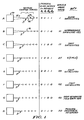
- FIG 1 illustrates the principles of ink jet drop formation useful in understanding the present invention.
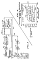
- Figure 2 is a software flow diagram illustrating the manner in which the processor of the present invention operates.
- Figure 3 is a circuit diagram illustrating the control circuit according to the present invention.
- Figure 4 is a graph useful in explaining the operation of the present invention.
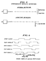
- Figure 5 illustrates the manner in which intermediate satellites may be detected.
- Figure 6 is a timing diagram useful in explaining the test pattern used for detecting the upper cardinal point.
- the nozzle 10 emits therefrom a stream of ink 12.
- a nozzle drive voltage is applied which voltage causes the stream to break up into a series of discrete drops 14.
- Smaller drops known in this art as satellites, form between the drops 14.
- the satellites 16 behave in a manner which is a function of the energy applied to the nozzle (measured in terms of the nozzle voltage).
- C(L) As the drive to the nozzle is increased, a point, designated herein as C(L), will occur. This term refers to a lower cardinal point. Cardinal is a term borrowed from optics terminology where it denotes an important point of a lens system, i.e., a focal point, a nodal point, or a principal point.
- C(L) is an important point because it represents the point at which the satellites separate from the leading and the following drops at the same time (see Figure 1D). Surface tension forces pull these satellites forward and backward with equal force. The result is that the satellites stay at a mid or intermediate point between the drops as they travel through space.
- C(L) It is this condition, referred to as C(L), that can be detected at a downstream point by detecting the satellites and the drops. At the point C(L) there will be a doubling of the normal drop frequency which can be detected. In all other cases, the satellites will have merged with either the leading or the trailing drops.
- Appropriate detectors are illustrated and described in connection with Figure 5 of this disclosure.
- the point C(L) will be detected by frequency doubling as the power to the nozzle drive is increased from a low level to a level just adequate to form intermediate satellites.
- an appropriate test signal is placed on a charging electrode so that both the drops and the intermediate satellites will be charged.
- the sensed drop frequency will double when intermediate satellites are present and pass the sensor.
- an optical detector may be employed which does not require charging of the drops and satellites but will detect a doubling in the number of drops passing the detector.
- the detector is positioned a sufficient distance downstream from the nozzle orifice to permit the satellites to merge.
- V(calc) Values of V(calc) calculated from the foregoing equation are plotted in Figure 4. These values of V(calc) all lie within the cross hatched area of the graph and represent nozzle drive voltages that produce quality printing.
- the nozzle 10 is connected to an ink supply 32 via an ink conduit 34.
- the ink stream is grounded intermediate the ink supply and nozzle 36.
- the nozzle has an acoustic energy applied to it, as for example, by means of a piezo-electric device as disclosed in the aforementioned U.S. patent 4,727,379.
- the drive voltage for the piezo-electric device is provided from a nozzle drive amplifier 38 via line 40.
- the amplifier is controlled by a processor 42, such as a microcomputer, via a digital to analog converter (D/A) 44.
- the controller 42 also operates charge amplifier 44 via D/A 46 to control the voltage applied to the charge tunnel 48.
- the charge tunnel 48 is disposed downstream of the nozzle 10 in the region where the drops are intended to form as the stream of ink breaks up into drops and satellites. In this manner selected drops can be charged for deflection onto a substrate or, if left uncharged, returned by way of a gutter to the ink supply 32.
- the controller 42 receives input signals from a capacitive pickup 50 downstream of the charge tunnel.
- the signal from the pickup 50 is provided to a preamplifier 52 and to a band pass filter 54 (a notch filter designed to pass a frequency equal to twice the normal drop frequency of the ink jet system).
- the capacitive pickup 50 detects the point C(L) in which the drop frequency has doubled due to the presence of intermediate satellites ( Figure 1B). That signal, analogue in nature, is passed by the filter 54 to a comparator 56 which provides a digital output when the input exceeds a threshold. This signals the controller that C(L) has been detected.
- the controller thus stores the corresponding nozzle drive voltage value.
- the second input of interest to controller 42 provides a signal indicating the occurrence of C(H), the fold back point illustrated in Figure 1G.
- This signal is produced on line 58 from a pickup 60 in electrical communication with the electrically conductive ink stream.
- the output of pickup 60 is provided to an integrating preamplifier 62 which, in turn, is provided to a comparator 64. As will be described, if the charge on the capacitor associated with preamplifier 62 exceeds a threshold set for comparator 64, a digital output is provided on line 58 to the controller.
- test signals are placed on the charge tunnel 48 for a period equal to 30 drop times.
- the wave form illustrated in Figure 6 is referenced to the drop clock wave form which may be, for example, 66 kilohertz.
- the charge tunnel 48 attempts to apply a charge to each ink drop formed as the droplets break off from the ink stream.
- the pickup 60 will detect whether or not the drops are successfully charged. For each drop which is charged an incremental charge is stored on the capacitor associated with the preamplifier 62.
- test video signals 1, 2, and 3 all of which are illustrated in Figure 6.
- Each test pattern is a quarter lambda out of phase from the preceding test pattern (where lambda is the droplet spacing). As a result, it is possible to accurately determine the location (in quarter lambdas, for example) of the droplet breakoff point relative to the positions of the two cardinal points.
- test video 1 and test video 2 are digital ones, while test video 0 and test video 3 are zero indicating that the latter two test videos did not result in charging of the droplets (This is due to the phase of the test video signals relative to the drop clock).
- the pattern of the successfully charged drops changes as indicated in Figure 1 in a predictable sequence based upon the phasing of the test video signals.
- C(H) there is a first phase reversal (additional phase reversals may occur at higher drive voltages). That is, instead of the expected phase pattern 1001 for Figure 1H, the pattern 0110 is observed, which pattern is exactly the same as Figure 1F.
- the circuit accurately detects C(H) the first fold back point where drop breakoff within the charge tunnel 48 is at a minimum distance from the nozzle.
- the comparator 64 is preferably sampled only once, at about 15 drop times after the start of each test video signal.
- the output from the comparator is a one or zero indicating that the drops were or were not successfully charged.
- test video signals have a pulse width of approximately 66% of the drop time and that each test video signal is one-quarter drop time out of phase with every other test video signal.
- the phasing sequence ends after the output of the comparator is recorded for the four video test signals.
- the drop separation point occurs earlier (nearer to the nozzle) as nozzle voltage increases. This is recognized by the detector as indicated by the pattern of ones marching from right to left in Figures A through G (and wrapping around). This continues until the fold back point, C(H) where the sequencing reverses itself and the detector signals this voltage value to the controller.
- the capacitive pickup 50 can be used for both purposes. That is, the pickup 50 can detect the C(L) value and, by connecting preamp 62 and comparator 64 to the capacitive pickup, it can also detect C(H). Thus, it is not necessary to use a separate pickup 60 behind the nozzle since the capacitive pickup 50 downstream of the charge tunnel can, if desired, perform both functions.
- FIG. 2 illustrates a software flow diagram suitable for performing the calculations according to the present invention. It is important to note that knowledge of the ink temperature is not necessary for a determination of a proper nozzle drive voltage.
- the controller 42 in the case where a capacitive pickup is utilized, sets the charge tunnel voltage to a constant value. It then sets the nozzle drive voltage to a minimum value via line 40. Nozzle drive voltage is slowly increased and the capacitive pickup is checked to determine if frequency doubling has occurred. If not, voltage increases, in small increments, until frequency doubling is detected. As indicated previously, frequency doubling indicates the condition where intermediate satellites, which are not merging, are being formed. When frequency doubling, is detected, the value of the nozzle drive voltage is recorded as C(L).
- the controller then initiates the phase control portion of its routine to detect C(H).
- the test video signals shown in Figure 6 are applied to the charge tunnel electrode.
- the sensor 60 or alternatively the capacitive pickup 50, is monitored to detect whether drops have been successfully charged for each of the four test signals.
- the software then checks to detect whether or not phase reversal has occurred. If not, the nozzle drive voltage is increased, in small increments, until phase reversal is detected. Upon detection, the nozzle drive voltage is recorded as C(H).
- V(calc) Upon obtaining values of C(H) and C(L), the value V(calc) is computed.
- This value V(calc), which is shown in Figure 4 is in the middle of the desirable operating range of the system and is thereafter used as the nozzle drive voltage. In summary form, this operation may be stated as follows:
- V(calc) requires a value alpha be specified which is ink dependent.
Landscapes
- Particle Formation And Scattering Control In Inkjet Printers (AREA)
- Recording Measured Values (AREA)
- Ink Jet (AREA)
Description
- This invention relates to ink jet printing systems and similar drop marking systems in which a supply of electrically conductive ink is provided to a nozzle. The ink is forced through a nozzle orifice while at the same time an exciting voltage is applied to the nozzle to cause the stream of ink to break into droplets which can be charged and deflected onto a substrate to be marked. Such ink jet technology is well known and, for example, see U.S. Patent Nos. 4,727,379 and 4,555,712.
- To ensure proper operating conditions for consistent printing quality, the exciting energy or voltage applied to the nozzle must be properly set during operation of the system. Presently, most ink jet printers require manual setting of the energy applied to the ink stream as it exits the nozzle. The appropriate value is either empirically determined by comparing what is seen to an existing diagram or by determining the drop separation point and comparing it with machine specifications. In either case, the resulting print quality varies.
- Efforts to provide automatic control of the modulation voltage have concentrated on detecting separation point position, relative to a fixed location, such as the charge tunnel. See, for example, published European patent specification EPA 0287373. Another approach is disclosed in U.S. Patent No. 4,638,325 which utilizes a small charging electrode and a downstream electrometer by which the drop separation point can be determined by observing the current at the electrometer as the separation point approaches the small electrode, the maximum current being produced when drop separation is closest to the small charging electrode. A system control microprocessor receives the digital ink jet current signal from the electrometer and is programmed to control the gain of a stimulation amplifier, of which the output is applied to the piezoelectric transducer on the ink jet printing head, by providing a reference signal to an automatic gain control circuit. In operation the stimulation amplitude is initially adjusted to a low level to allow the length of the ink filament to approach its natural unstimulated length. The stimulation amplitude is then monotonically increased whilst the charge imparted to the ink jet is monitored by the electrometer. As the stimulation amplitude is increased, the ink filament becomes shorter and the ink drop separation approaches the narrow charging electrode. In this manner the ink jet current registered by the electrometer provides a signal that is proportional to the length of the ink filament. The system control microprocessor is used to increase the stimulation reference signal in increments whilst monitoring the jet current signal provided by the electrometer. The jet current signal is recorded and a peak is detected representing the entry into overdrive, that is a region of stimulation above the minimum filament length in which satellite drops are produced and drop deflection is stated as being difficult to control. The stimulation amplitude is then set at some predetermined point below the peak that is found to provide reliable stimulation by computing the reference level as a function of the reference level at the peak. It is suggested that the reference level may be set to the stimulation amplitude at the peak minus 25mV, that is a constant offset from the stimulation amplitude at peak.
- U.S. Patent No. 4,638,325 accordingly teaches that the stimulation amplitude applied to the nozzle of an ink jet printer may be set by a control circuit which includes detecting means (in the form of a piezoelectric feedback transducer) for determining the value of the stimulation amplitude as its magnitude is slowly increased from a minimum value and for detecting the value of the stimulation amplitude at which droplet formation occurs closest to the nozzle (that is the peak representing entry into overdrive).
- The above teaching does not take into account the basic reason for maintaining consistent drop charging conditions. The drop separation point varies greatly with the surface tension and viscosity of the ink, therefore, simply holding the separation point constant still results in different satellite conditions and variable print quality. In short, maintaining the drop separation point constant is not a satisfactory solution to the problem.
- What is desired is a system which can determine a range of proper printing nozzle drive voltages and then compute a satisfactory intermediate value within said range. Such a system should be temperature independent over a wide range of operating temperatures to result in a significantly better control system.
- According to one aspect of the invention a detecting means is arranged to detect the value C(L) of the exciting voltage at which droplet frequency doubles and a calculating means is provided to receive as inputs the values C(L) and C(H) and to calculate therefrom the magnitude of the exciting voltage to be utilised for printing. The detecting means may include either a capacitive pick up or an optical detector downstream of the nozzle to detect the electrically charged droplets. The detecting means may further include circuit means for providing an output signal to the calculating means when the detected droplet frequency doubles.
- Means may be provided for applying electrical test patterns to the droplets, the patterns varying in phase relative to the droplet timing whereby only some of the test patterns successfully charge the droplets, and wherein the detecting means includes a pick up to detect which of the droplets have been charged, and the calculating means includes means for determining the C(H) value from the change in the sequence of charge patterns. The means for applying the test patterns to the droplets may include a charge amplifier and a charge tunnel positioned downstream of the nozzle in the region of droplet formation. Means may also be provided for slowly increasing the exciting voltage from a minimum value.
- The calculating means is preferably arranged to calculate the magnitude of the exciting voltage to be used for printing according to the the equation:

where alpha is a value related to the ink. - According to another aspect of the invention a method of determining the exciting voltage to be applied to the nozzle of an ink jet printer to break a stream of ink into droplets for printing, includes detecting the value C(L) of the existing voltage at which the droplet frequency doubles due to the formation of intermediate non-merging satellite droplets, and by calculating the value V(CALC) of the exciting voltage to be used for printing using the equation:

where alpha is a value related to the ink. This method may also include detecting the value C(L) by charging the ink droplets and by detecting the charges on the droplets sufficiently downstream of the nozzle to eliminate the presence of merging satellite droplets. The method may include detecting the value C(L) by optically detecting the ink droplets sufficinetly downstream of the nozzle to eliminate the presence of merging satellite droplets. The method may include detecting the value C(H) by - (i) applying electrical test patterns to the ink droplets such that the patterns will vary in phase relative to the ink droplet timing whereby only some of the test patterns will successfully charge the droplets,
- (ii) detecting which droplets have been successfully charged, and
- (iii) determining the value C(H) from the change in the sequence of charge patterns.
- The present invention enables a nozzle control system to monitor the condition of the satellite drops and the drop breakoff point accurately and to compute therefrom a satisfactory range of nozzle drive voltages for operating an ink jet printer.
- A further advantage of the present invention is that it enables automation of the nozzle voltage for best quality printing using a continuous ink jet printer regardless of ink type and temperature. Problems can also be avoided with recombining satellites that occur when holding the drop separation point constant while ink type and temperature vary. These cause unwanted charge variations because a satellite which carries part of the charge of its parent charged drop will transfer that charge to the drop following when merging occurs.
- Figure 1 illustrates the principles of ink jet drop formation useful in understanding the present invention.
- Figure 2 is a software flow diagram illustrating the manner in which the processor of the present invention operates.
- Figure 3 is a circuit diagram illustrating the control circuit according to the present invention.
- Figure 4 is a graph useful in explaining the operation of the present invention.
- Figure 5 illustrates the manner in which intermediate satellites may be detected.
- Figure 6 is a timing diagram useful in explaining the test pattern used for detecting the upper cardinal point.
- Referring to Figure 1, there are a series of nozzles shown. The
nozzle 10 emits therefrom a stream of ink 12. A nozzle drive voltage is applied which voltage causes the stream to break up into a series of discrete drops 14. Smaller drops, known in this art as satellites, form between the drops 14. Thesatellites 16 behave in a manner which is a function of the energy applied to the nozzle (measured in terms of the nozzle voltage). - Referring to Figure 1, when the applied acoustic power to the ink stream is low, the natural behavior of the satellites is to form independently of the drops and then fall back and merge with the drops which follow. This is referred to as rearward merging satellites or slow satellites and is illustrated in Figure 1A. The fall back and merging occurs in approximately ten drop periods depending upon the physical parameters of the ink (viscosity, surface tension, specific gravity, etc.).
- As the drive to the nozzle is increased, a point, designated herein as C(L), will occur. This term refers to a lower cardinal point. Cardinal is a term borrowed from optics terminology where it denotes an important point of a lens system, i.e., a focal point, a nodal point, or a principal point. For purposes of the present specification, C(L) is an important point because it represents the point at which the satellites separate from the leading and the following drops at the same time (see Figure 1D). Surface tension forces pull these satellites forward and backward with equal force. The result is that the satellites stay at a mid or intermediate point between the drops as they travel through space. It is this condition, referred to as C(L), that can be detected at a downstream point by detecting the satellites and the drops. At the point C(L) there will be a doubling of the normal drop frequency which can be detected. In all other cases, the satellites will have merged with either the leading or the trailing drops. Appropriate detectors are illustrated and described in connection with Figure 5 of this disclosure.
- Virtually all nozzles used for ink jet printing systems exhibit such intermediate satellites which are neither forward nor rearward merging. The point C(L) will be detected by frequency doubling as the power to the nozzle drive is increased from a low level to a level just adequate to form intermediate satellites.
- In one embodiment of the Figure 5 detector, an appropriate test signal is placed on a charging electrode so that both the drops and the intermediate satellites will be charged. The sensed drop frequency will double when intermediate satellites are present and pass the sensor. Alternatively, an optical detector may be employed which does not require charging of the drops and satellites but will detect a doubling in the number of drops passing the detector.
- In either case, the detector is positioned a sufficient distance downstream from the nozzle orifice to permit the satellites to merge.
- In addition to a lower cardinal point, C(L), most ink jet nozzles also exhibit what can be designated as an upper cardinal point, C(H). This point can be observed by slowly increasing the power to the nozzle and observing the point of drop separation. As the power to the nozzle is increased from a low level (Figure 1A), the drop separation point, designated S, moves closer to the nozzle until it reaches (Figure 1G) its minimum distance from the nozzle. This is designated the upper cardinal power point C(H). Thereafter, the breakoff point moves away from the nozzle (Figure 1H). This fold back or reversal can be sensed by appropriate circuitry and software. A description of the circuitry and methodology for detecting the upper cardinal point C(H) is provided in connection with a description of Figure 3.
- First, however, with reference to Figure 4, there is shown a graph which demonstrates the characteristics of a typical ink used in an ink jet printing system. This ink, manufactured by the assignee of the present invention, and designated 16-8200, was utilized with a nozzle of the type described in U.S. Patent No. 4,727,329, which patent is hereby incorporated by reference. The cross hatched area on the graph represent nozzle drive voltages that produce good quality printing over a temperature range of approximately 4,44 °C to 43,33 °C (40 degrees F to 110 degrees F). The lower and upper cardinal power points, C(L) and C(H), are also plotted for the same nozzle and ink composition. From this information, it is possible to calculate a voltage value, V(calc), from the following equation:

where alpha is a function of the ink described hereafter. - Values of V(calc) calculated from the foregoing equation are plotted in Figure 4. These values of V(calc) all lie within the cross hatched area of the graph and represent nozzle drive voltages that produce quality printing.
- Referring to Figures 1 and 3, circuitry suitable for practicing the invention will be described. The
nozzle 10 is connected to an ink supply 32 via anink conduit 34. The ink stream is grounded intermediate the ink supply and nozzle 36. The nozzle has an acoustic energy applied to it, as for example, by means of a piezo-electric device as disclosed in the aforementioned U.S. patent 4,727,379. The drive voltage for the piezo-electric device is provided from anozzle drive amplifier 38 vialine 40. In turn, the amplifier is controlled by aprocessor 42, such as a microcomputer, via a digital to analog converter (D/A) 44. Thecontroller 42 also operatescharge amplifier 44 via D/A 46 to control the voltage applied to thecharge tunnel 48. As is well known in this art, thecharge tunnel 48 is disposed downstream of thenozzle 10 in the region where the drops are intended to form as the stream of ink breaks up into drops and satellites. In this manner selected drops can be charged for deflection onto a substrate or, if left uncharged, returned by way of a gutter to the ink supply 32. - According to the present invention, the
controller 42 receives input signals from acapacitive pickup 50 downstream of the charge tunnel. The signal from thepickup 50 is provided to a preamplifier 52 and to a band pass filter 54 (a notch filter designed to pass a frequency equal to twice the normal drop frequency of the ink jet system). Thus, thecapacitive pickup 50 detects the point C(L) in which the drop frequency has doubled due to the presence of intermediate satellites (Figure 1B). That signal, analogue in nature, is passed by the filter 54 to acomparator 56 which provides a digital output when the input exceeds a threshold. This signals the controller that C(L) has been detected. The controller thus stores the corresponding nozzle drive voltage value. - The second input of interest to
controller 42 provides a signal indicating the occurrence of C(H), the fold back point illustrated in Figure 1G. This signal is produced online 58 from apickup 60 in electrical communication with the electrically conductive ink stream. The output ofpickup 60 is provided to an integratingpreamplifier 62 which, in turn, is provided to acomparator 64. As will be described, if the charge on the capacitor associated withpreamplifier 62 exceeds a threshold set forcomparator 64, a digital output is provided online 58 to the controller. - To understand the function of the
comparator 64, it is necessary to refer to Figures 1, 3 and 6. To determine C(H), test signals are placed on thecharge tunnel 48 for a period equal to 30 drop times. For example, the signal denotedTest Video 0 in Figure 6. The wave form illustrated in Figure 6 is referenced to the drop clock wave form which may be, for example, 66 kilohertz. During the time that thetest video 0 signal is high, thecharge tunnel 48 attempts to apply a charge to each ink drop formed as the droplets break off from the ink stream. During this period thepickup 60 will detect whether or not the drops are successfully charged. For each drop which is charged an incremental charge is stored on the capacitor associated with thepreamplifier 62. If most of the drops are successfully charged by the test video signal, the voltage from the preamplifier will exceed the threshold set on thecomparator 64 and signal the controller. This sequence is then repeated for test video signals 1, 2, and 3, all of which are illustrated in Figure 6. Each test pattern is a quarter lambda out of phase from the preceding test pattern (where lambda is the droplet spacing). As a result, it is possible to accurately determine the location (in quarter lambdas, for example) of the droplet breakoff point relative to the positions of the two cardinal points. - The result of this operation is illustrated in Figure 1 where there is shown for each of Figures 1A-H a four bit binary code representing the results of applying the
test video signals 0 through 3. Thus, for example, with respect to Figure 1B,test video 1 andtest video 2 are digital ones, whiletest video 0 andtest video 3 are zero indicating that the latter two test videos did not result in charging of the droplets (This is due to the phase of the test video signals relative to the drop clock). - As the drive voltage to the nozzle increases, the pattern of the successfully charged drops changes as indicated in Figure 1 in a predictable sequence based upon the phasing of the test video signals. At the cardinal point C(H), however, there is a first phase reversal (additional phase reversals may occur at higher drive voltages). That is, instead of the expected
phase pattern 1001 for Figure 1H, thepattern 0110 is observed, which pattern is exactly the same as Figure 1F. Thus, the circuit accurately detects C(H) the first fold back point where drop breakoff within thecharge tunnel 48 is at a minimum distance from the nozzle. - In practice, the
comparator 64 is preferably sampled only once, at about 15 drop times after the start of each test video signal. The output from the comparator is a one or zero indicating that the drops were or were not successfully charged. - It will be recognized from the review of Figure 6 that the four test video signals have a pulse width of approximately 66% of the drop time and that each test video signal is one-quarter drop time out of phase with every other test video signal. The phasing sequence ends after the output of the comparator is recorded for the four video test signals.
- As can be seen from Figure 1, the drop separation point occurs earlier (nearer to the nozzle) as nozzle voltage increases. This is recognized by the detector as indicated by the pattern of ones marching from right to left in Figures A through G (and wrapping around). This continues until the fold back point, C(H) where the sequencing reverses itself and the detector signals this voltage value to the controller.
- While the Figure 3 embodiment shows separate pickups for C(L) and C(H), it will be recognized by those skilled in the art that the
capacitive pickup 50 can be used for both purposes. That is, thepickup 50 can detect the C(L) value and, by connectingpreamp 62 andcomparator 64 to the capacitive pickup, it can also detect C(H). Thus, it is not necessary to use aseparate pickup 60 behind the nozzle since thecapacitive pickup 50 downstream of the charge tunnel can, if desired, perform both functions. - It will be recognized by those skilled in the art that if a
separate pickup 60 is utilized for detecting C(H) it is then possible to use an optical or an acoustical pickup in place of thecapacitive pickup 50 to detect C(L). The advantage of using an optical or acoustical pickup is that the drops do not have to be charged to be detected. - When the controller has received the information necessary to determine C(L) and C(H), it employs equation one to calculate V(calc). Figure 2 illustrates a software flow diagram suitable for performing the calculations according to the present invention. It is important to note that knowledge of the ink temperature is not necessary for a determination of a proper nozzle drive voltage.
- Referring to Figure 2, determination of the cardinal points will be described. The
controller 42, in the case where a capacitive pickup is utilized, sets the charge tunnel voltage to a constant value. It then sets the nozzle drive voltage to a minimum value vialine 40. Nozzle drive voltage is slowly increased and the capacitive pickup is checked to determine if frequency doubling has occurred. If not, voltage increases, in small increments, until frequency doubling is detected. As indicated previously, frequency doubling indicates the condition where intermediate satellites, which are not merging, are being formed. When frequency doubling, is detected, the value of the nozzle drive voltage is recorded as C(L). - The controller then initiates the phase control portion of its routine to detect C(H). The test video signals shown in Figure 6 are applied to the charge tunnel electrode. The
sensor 60, or alternatively thecapacitive pickup 50, is monitored to detect whether drops have been successfully charged for each of the four test signals. The software then checks to detect whether or not phase reversal has occurred. If not, the nozzle drive voltage is increased, in small increments, until phase reversal is detected. Upon detection, the nozzle drive voltage is recorded as C(H). - Upon obtaining values of C(H) and C(L), the value V(calc) is computed. This value V(calc), which is shown in Figure 4 is in the middle of the desirable operating range of the system and is thereafter used as the nozzle drive voltage. In summary form, this operation may be stated as follows:
- I.
- A. Assuming an electrical charge detector, begin by applying a constant charge voltage to the charging electrode (charge tunnel).
- B. Increase the applied nozzle drive voltage slowly from a low level, i.e., less than 9 volts, sine wave, peak-to-peak.
- C. Monitor the downstream detector for a frequency twice that of the drop frequency, that is, search for intermediate satellites.
- D. Once the doubled frequency is detected, record the voltage level as the lower cardinal power point C(L).
- II.
- A. Switch to the phasing system and apply sequential phasing voltages to the charging electrode.
- B. Observe the sequential direction of "good" phase (in our example "1"s) as nozzle drive voltage is increased.
- C. Record the nozzle voltage as C(H) when the direction or sequence of the good phase reverses.
- D. Calculate the proper drive voltage from eq(1) for the ink and apply it the nozzle.
- Referring again to equation one, it will be noted that the calculation of the value V(calc) requires a value alpha be specified which is ink dependent. This value alpha can be determined as follows. Since the good printing region lies sandwiched between the lower and upper cardinal power points (see Figure 4) an acceptable solution would be to set alpha = 1. This would locate V(calc) midway between C(L) and C(H), however, some added tolerance may be gained by choosing slightly smaller or slightly larger values. A smaller alpha would lower V(calc) and a larger alpha would raise V(calc). It is desirable to adjust alpha for each ink to optimize its printing range. This can easily be done by calculating V(calc) for a specific alpha and plotting the results on a graph representing the desirable range of a particular ink. In other words, if desired, alpha may be empirically optimized for each ink composition.
Claims (12)
- A control circuit, for setting the magnitude of the exciting voltage applied to the nozzle of an ink jet printer to break a stream of ink into droplets, including detecting means for determining the value of the exciting voltage as its magnitude is slowly increased from a minimum value and detecting the value C(H) of the exciting voltage at which droplet formation occurs closest to the nozzle, characterised in that detecting means (50, 52, 54, 56) is arranged to detect the value C(L) of the exciting voltage at which droplet frequency doubles and a calculatiing means (42) is provided to receive as inputs the values C(L) and C(H) and to calculate therefrom the magnitude of the exciting voltage to be utilised for printing.
- A control circuit, as in Claim 1, characterised in that the detecting means includes a capacitive pick up (50) downstream of the nozzle (10) to detect the electrically charged droplets.
- A control circuit, as in Claim 1, characterised in that the detecting means includes an optical detector located downstream of the nozzle (10) for detecting the droplets passing the detector.
- A control circuit, as in Claim 2 or 3, characterised in that the detecting means further includes circuit means (52, 54, 56) for providing an output signal to the calculating means (42) when the detected droplet frequency doubles.
- A control circuit, as in any preceding claim, characterised in that means (42, 44, 46, 48) are provided for applying electrical test patterns to the droplets, the patterns varying in phase relative to the droplet timing whereby only some of the test patterns successfully charge the droplets, and wherein the detecting means includes a pick up (50) to detect which of the droplets have been charged, and the calculating means (42) includes means for determining the C(H) value from the change in the sequence of charge patterns.
- A control circuit, as in Claim 5, characterised in that the means (42, 44, 46, 48) for applying the test patterns to the droplets includes a charge amplifier (44) and a charge tunnel (48) positioned downstream of the nozzle (10) in the region of droplet formation.
- A control circuit, as in any preceding claim, characterised in that means (38, 40, 42, 44) are provided for slowly increasing the exciting voltage from a minimum value.
- A control circuit, as in any preceding claim, characterised in that the calculating means (42) is arranged to calculate the magnitude of the exciting voltage to be used for printing according to the equation:

where alpha is a value related to the ink. - A method of determining the exciting voltage to be applied to the nozzle of an ink jet printer to break a stream of ink into droplets for printing, including(a) slowly increasing the exciting voltage from a minimum value,(b) detecting the existing voltage,(c) detecting and recording the value C(H) of the exciting voltage at which droplet formation first occurs closest to the nozzle, and(d) calculating from the value of C(H) the value V(CALC) of the exciting voltage to be used for printing,characterised by additionally detecting the value C(L) of the existing voltage at which the droplet frequency doubles due to the formation of intermediate non-merging satellite droplets, and by calculating the value V(CALC) of the exciting voltage to be used for printing using the equation:

where alpha is a value related to the ink. - A method, as in Claim 9, characterised by detecting the value C(L) by charging the ink droplets and by detecting the charges on the droplets sufficiently downstream of the nozzle to eliminate the presence of merging satellite droplets.
- A method, as in Claim 9, characterised by detecting the value C(L) by optically detecting the ink droplets sufficiently downstream of the nozzle to eliminate the presence of merging satellite droplets.
- A method, as in any of Claims 9 to 11, characterised by detecting the value C(H) by(i) applying electrical test patterns to the ink droplets such that the patterns will vary in phase relative to the ink droplet timing whereby only some of the test patterns will successfully charge the droplets,(ii) detecting which droplets have been successfully charged, and(iii) determining the value C(H) from the change in the sequence of charge patterns.
Priority Applications (1)
| Application Number | Priority Date | Filing Date | Title |
|---|---|---|---|
| EP94202383A EP0628412B1 (en) | 1989-03-31 | 1990-03-22 | Nozzle drive control system and method for ink jet printing |
Applications Claiming Priority (2)
| Application Number | Priority Date | Filing Date | Title |
|---|---|---|---|
| US33200989A | 1989-03-31 | 1989-03-31 | |
| US332009 | 1989-03-31 |
Related Child Applications (1)
| Application Number | Title | Priority Date | Filing Date |
|---|---|---|---|
| EP94202383.9 Division-Into | 1990-03-22 |
Publications (2)
| Publication Number | Publication Date |
|---|---|
| EP0390427A1 EP0390427A1 (en) | 1990-10-03 |
| EP0390427B1 true EP0390427B1 (en) | 1995-03-22 |
Family
ID=23296316
Family Applications (2)
| Application Number | Title | Priority Date | Filing Date |
|---|---|---|---|
| EP19900303101 Expired - Lifetime EP0390427B1 (en) | 1989-03-31 | 1990-03-22 | Nozzle drive control system and method for ink jet printing |
| EP94202383A Expired - Lifetime EP0628412B1 (en) | 1989-03-31 | 1990-03-22 | Nozzle drive control system and method for ink jet printing |
Family Applications After (1)
| Application Number | Title | Priority Date | Filing Date |
|---|---|---|---|
| EP94202383A Expired - Lifetime EP0628412B1 (en) | 1989-03-31 | 1990-03-22 | Nozzle drive control system and method for ink jet printing |
Country Status (6)
| Country | Link |
|---|---|
| EP (2) | EP0390427B1 (en) |
| JP (1) | JP2858833B2 (en) |
| AU (1) | AU620941B2 (en) |
| CA (1) | CA2001041C (en) |
| DE (2) | DE69031431T2 (en) |
| ES (2) | ES2069681T3 (en) |
Families Citing this family (3)
| Publication number | Priority date | Publication date | Assignee | Title |
|---|---|---|---|---|
| US5396274A (en) * | 1992-05-20 | 1995-03-07 | Videojet Systems International, Inc. | Variable frequency ink jet printer |
| US8628176B2 (en) * | 2007-11-10 | 2014-01-14 | Videojet Technologies Inc. | Electromechanical converter for ink jet printing |
| GB2602051B (en) * | 2020-12-16 | 2024-09-25 | Domino Uk Ltd | Dynamic modulating voltage adjustment |
Family Cites Families (10)
| Publication number | Priority date | Publication date | Assignee | Title |
|---|---|---|---|---|
| JPS5655268A (en) * | 1979-10-11 | 1981-05-15 | Sharp Corp | Controller for particle of ink in ink jet printer |
| JPS604065A (en) * | 1983-06-23 | 1985-01-10 | Hitachi Ltd | Ink jet recorder |
| JPH0829590B2 (en) * | 1985-03-04 | 1996-03-27 | 株式会社日立製作所 | Inkjet recording device |
| US4631549A (en) * | 1985-08-15 | 1986-12-23 | Eastman Kodak Company | Method and apparatus for adjusting stimulation amplitude in continuous ink jet printer |
| US4638325A (en) * | 1985-09-09 | 1987-01-20 | Eastman Kodak Company | Ink jet filament length and stimulation amplitude assessment system |
| JPH0684076B2 (en) * | 1986-02-19 | 1994-10-26 | 株式会社日立製作所 | Inkjet recording device |
| US4688047A (en) * | 1986-08-21 | 1987-08-18 | Eastman Kodak Company | Method and apparatus for sensing satellite ink drop charge and adjusting ink pressure |
| GB8708885D0 (en) * | 1987-04-14 | 1987-05-20 | Domino Printing Sciences Plc | Ink jet printing |
| GB8725465D0 (en) * | 1987-10-30 | 1987-12-02 | Linx Printing Tech | Ink jet printers |
| US4878064A (en) * | 1988-10-31 | 1989-10-31 | Eastman Kodak Company | Continuous ink jet stimulation adjustment based on overdrive detection |
-
1989
- 1989-10-19 CA CA 2001041 patent/CA2001041C/en not_active Expired - Fee Related
- 1989-11-17 AU AU45302/89A patent/AU620941B2/en not_active Ceased
- 1989-12-21 JP JP1332523A patent/JP2858833B2/en not_active Expired - Fee Related
-
1990
- 1990-03-22 EP EP19900303101 patent/EP0390427B1/en not_active Expired - Lifetime
- 1990-03-22 DE DE1990631431 patent/DE69031431T2/en not_active Expired - Fee Related
- 1990-03-22 ES ES90303101T patent/ES2069681T3/en not_active Expired - Lifetime
- 1990-03-22 ES ES94202383T patent/ES2106440T3/en not_active Expired - Lifetime
- 1990-03-22 DE DE1990617931 patent/DE69017931T2/en not_active Expired - Fee Related
- 1990-03-22 EP EP94202383A patent/EP0628412B1/en not_active Expired - Lifetime
Also Published As
| Publication number | Publication date |
|---|---|
| DE69017931T2 (en) | 1995-07-20 |
| EP0628412B1 (en) | 1997-09-10 |
| DE69031431T2 (en) | 1998-01-22 |
| AU4530289A (en) | 1990-10-04 |
| JPH02274556A (en) | 1990-11-08 |
| ES2069681T3 (en) | 1995-05-16 |
| AU620941B2 (en) | 1992-02-27 |
| ES2106440T3 (en) | 1997-11-01 |
| DE69017931D1 (en) | 1995-04-27 |
| JP2858833B2 (en) | 1999-02-17 |
| EP0628412A3 (en) | 1995-06-07 |
| CA2001041C (en) | 1994-03-08 |
| EP0390427A1 (en) | 1990-10-03 |
| DE69031431D1 (en) | 1997-10-16 |
| CA2001041A1 (en) | 1990-09-30 |
| EP0628412A2 (en) | 1994-12-14 |
Similar Documents
| Publication | Publication Date | Title |
|---|---|---|
| US5196860A (en) | Ink jet droplet frequency drive control system | |
| US3769630A (en) | Ink jet synchronization and failure detection system | |
| US3969733A (en) | Sub-harmonic phase control for an ink jet recording system | |
| CA1085903A (en) | Method and apparatus for adjusting the velocity of ink drops in an ink jet printer | |
| US4047183A (en) | Method and apparatus for controlling the formation and shape of droplets in an ink jet stream | |
| EP0039772B1 (en) | Multinozzle ink jet printer and method of operating such a printer | |
| WO1987001075A1 (en) | Method and apparatus for phase detection and adjustment in ink jet printers | |
| US4435720A (en) | Deflection control type ink jet printing apparatus | |
| CA1315595C (en) | Method and apparatus for controlling the electrical charging of drops in an ink jet recording apparatus | |
| US4994821A (en) | Continuous ink jet printer apparatus having improved short detection construction | |
| US4612553A (en) | Method for operational status checks of an ink jet printer | |
| EP0628412B1 (en) | Nozzle drive control system and method for ink jet printing | |
| US4864323A (en) | Continuous ink jet printing | |
| US5523778A (en) | Segmented charge tunnel for drop charging in a printhead | |
| US4638325A (en) | Ink jet filament length and stimulation amplitude assessment system | |
| JPS6280053A (en) | Multi-nozzle ink jet recorder | |
| JP2891439B2 (en) | Continuous jet ink jet recording apparatus and method for automatically adjusting the ink jet flight axis | |
| US4470052A (en) | A-C Coupled, modulator based, phase-error sensing for IJP | |
| US4688047A (en) | Method and apparatus for sensing satellite ink drop charge and adjusting ink pressure | |
| JP2727571B2 (en) | Ink jet printer | |
| US5502474A (en) | Print pulse phase control | |
| WO1994002318A1 (en) | Ink jet printers and methods for their operation | |
| SU991457A1 (en) | Printing device | |
| JPS61102258A (en) | Liquid droplet detector of ink jet recorder | |
| JPS5942966A (en) | Ink jet recording mechanism |
Legal Events
| Date | Code | Title | Description |
|---|---|---|---|
| PUAI | Public reference made under article 153(3) epc to a published international application that has entered the european phase |
Free format text: ORIGINAL CODE: 0009012 |
|
| AK | Designated contracting states |
Kind code of ref document: A1 Designated state(s): CH DE ES FR GB IT LI NL SE |
|
| 17P | Request for examination filed |
Effective date: 19910326 |
|
| 17Q | First examination report despatched |
Effective date: 19921014 |
|
| GRAA | (expected) grant |
Free format text: ORIGINAL CODE: 0009210 |
|
| RAP1 | Party data changed (applicant data changed or rights of an application transferred) |
Owner name: VIDEOJET SYSTEMS INTERNATIONAL, INC. |
|
| AK | Designated contracting states |
Kind code of ref document: B1 Designated state(s): CH DE ES FR GB IT LI NL SE |
|
| XX | Miscellaneous (additional remarks) |
Free format text: TEILANMELDUNG 94202383.9 EINGEREICHT AM 22/03/90. |
|
| ITF | It: translation for a ep patent filed | ||
| REF | Corresponds to: |
Ref document number: 69017931 Country of ref document: DE Date of ref document: 19950427 |
|
| REG | Reference to a national code |
Ref country code: ES Ref legal event code: FG2A Ref document number: 2069681 Country of ref document: ES Kind code of ref document: T3 |
|
| ET | Fr: translation filed | ||
| PLBE | No opposition filed within time limit |
Free format text: ORIGINAL CODE: 0009261 |
|
| STAA | Information on the status of an ep patent application or granted ep patent |
Free format text: STATUS: NO OPPOSITION FILED WITHIN TIME LIMIT |
|
| 26N | No opposition filed | ||
| REG | Reference to a national code |
Ref country code: GB Ref legal event code: IF02 |
|
| PGFP | Annual fee paid to national office [announced via postgrant information from national office to epo] |
Ref country code: SE Payment date: 20020306 Year of fee payment: 13 |
|
| PGFP | Annual fee paid to national office [announced via postgrant information from national office to epo] |
Ref country code: ES Payment date: 20020315 Year of fee payment: 13 |
|
| PGFP | Annual fee paid to national office [announced via postgrant information from national office to epo] |
Ref country code: NL Payment date: 20020328 Year of fee payment: 13 Ref country code: CH Payment date: 20020328 Year of fee payment: 13 |
|
| PG25 | Lapsed in a contracting state [announced via postgrant information from national office to epo] |
Ref country code: SE Free format text: LAPSE BECAUSE OF NON-PAYMENT OF DUE FEES Effective date: 20030323 |
|
| PG25 | Lapsed in a contracting state [announced via postgrant information from national office to epo] |
Ref country code: ES Free format text: LAPSE BECAUSE OF NON-PAYMENT OF DUE FEES Effective date: 20030324 |
|
| PG25 | Lapsed in a contracting state [announced via postgrant information from national office to epo] |
Ref country code: LI Free format text: LAPSE BECAUSE OF NON-PAYMENT OF DUE FEES Effective date: 20030331 Ref country code: CH Free format text: LAPSE BECAUSE OF NON-PAYMENT OF DUE FEES Effective date: 20030331 |
|
| PG25 | Lapsed in a contracting state [announced via postgrant information from national office to epo] |
Ref country code: NL Free format text: LAPSE BECAUSE OF NON-PAYMENT OF DUE FEES Effective date: 20031001 |
|
| EUG | Se: european patent has lapsed | ||
| REG | Reference to a national code |
Ref country code: CH Ref legal event code: PL |
|
| NLV4 | Nl: lapsed or anulled due to non-payment of the annual fee |
Effective date: 20031001 |
|
| REG | Reference to a national code |
Ref country code: ES Ref legal event code: FD2A Effective date: 20030324 |
|
| PG25 | Lapsed in a contracting state [announced via postgrant information from national office to epo] |
Ref country code: IT Free format text: LAPSE BECAUSE OF NON-PAYMENT OF DUE FEES Effective date: 20050322 |
|
| PGFP | Annual fee paid to national office [announced via postgrant information from national office to epo] |
Ref country code: DE Payment date: 20070315 Year of fee payment: 18 |
|
| PGFP | Annual fee paid to national office [announced via postgrant information from national office to epo] |
Ref country code: GB Payment date: 20070321 Year of fee payment: 18 |
|
| PGFP | Annual fee paid to national office [announced via postgrant information from national office to epo] |
Ref country code: FR Payment date: 20070308 Year of fee payment: 18 |
|
| GBPC | Gb: european patent ceased through non-payment of renewal fee |
Effective date: 20080322 |
|
| REG | Reference to a national code |
Ref country code: FR Ref legal event code: ST Effective date: 20081125 |
|
| PG25 | Lapsed in a contracting state [announced via postgrant information from national office to epo] |
Ref country code: DE Free format text: LAPSE BECAUSE OF NON-PAYMENT OF DUE FEES Effective date: 20081001 |
|
| PG25 | Lapsed in a contracting state [announced via postgrant information from national office to epo] |
Ref country code: FR Free format text: LAPSE BECAUSE OF NON-PAYMENT OF DUE FEES Effective date: 20080331 |
|
| PG25 | Lapsed in a contracting state [announced via postgrant information from national office to epo] |
Ref country code: GB Free format text: LAPSE BECAUSE OF NON-PAYMENT OF DUE FEES Effective date: 20080322 |