EP0390283A1 - Nozzle configuration for an ink-jet printer and process for operating such a nozzle configuration - Google Patents
Nozzle configuration for an ink-jet printer and process for operating such a nozzle configuration Download PDFInfo
- Publication number
- EP0390283A1 EP0390283A1 EP90200736A EP90200736A EP0390283A1 EP 0390283 A1 EP0390283 A1 EP 0390283A1 EP 90200736 A EP90200736 A EP 90200736A EP 90200736 A EP90200736 A EP 90200736A EP 0390283 A1 EP0390283 A1 EP 0390283A1
- Authority
- EP
- European Patent Office
- Prior art keywords
- nozzle
- charging electrode
- ink
- nozzle configuration
- channel
- Prior art date
- Legal status (The legal status is an assumption and is not a legal conclusion. Google has not performed a legal analysis and makes no representation as to the accuracy of the status listed.)
- Granted
Links
Images


Classifications
-
- B—PERFORMING OPERATIONS; TRANSPORTING
- B41—PRINTING; LINING MACHINES; TYPEWRITERS; STAMPS
- B41J—TYPEWRITERS; SELECTIVE PRINTING MECHANISMS, i.e. MECHANISMS PRINTING OTHERWISE THAN FROM A FORME; CORRECTION OF TYPOGRAPHICAL ERRORS
- B41J2/00—Typewriters or selective printing mechanisms characterised by the printing or marking process for which they are designed
- B41J2/005—Typewriters or selective printing mechanisms characterised by the printing or marking process for which they are designed characterised by bringing liquid or particles selectively into contact with a printing material
- B41J2/01—Ink jet
- B41J2/07—Ink jet characterised by jet control
- B41J2/075—Ink jet characterised by jet control for many-valued deflection
- B41J2/08—Ink jet characterised by jet control for many-valued deflection charge-control type
- B41J2/085—Charge means, e.g. electrodes
-
- B—PERFORMING OPERATIONS; TRANSPORTING
- B41—PRINTING; LINING MACHINES; TYPEWRITERS; STAMPS
- B41J—TYPEWRITERS; SELECTIVE PRINTING MECHANISMS, i.e. MECHANISMS PRINTING OTHERWISE THAN FROM A FORME; CORRECTION OF TYPOGRAPHICAL ERRORS
- B41J2/00—Typewriters or selective printing mechanisms characterised by the printing or marking process for which they are designed
- B41J2/005—Typewriters or selective printing mechanisms characterised by the printing or marking process for which they are designed characterised by bringing liquid or particles selectively into contact with a printing material
- B41J2/01—Ink jet
- B41J2/17—Ink jet characterised by ink handling
- B41J2/20—Ink jet characterised by ink handling for preventing or detecting contamination of compounds
Definitions
- the present invention relates to a nozzle configuration for forming, charging and deflecting ink drops in an ink-jet printer, comprising a drop-formation nozzle, a charging electrode provided with a passage, and deflection plates, the central axes of said parts lying in line with one another.
- Such a nozzle configuration is used in an ink-jet printer in order to charge drops which are formed under pressure, starting from a drop formation nozzle, while passing through the passage of a charging electrode, and subsequently to deflect them, through selective excitation of a set of deflection plates, depending on the final destination of a particular drop or series of drops.
- the nozzle configurations can also be designed in such a way that the drops are charged selectively through selective excitation of the charging electrode; the deflection plates are then connected to a constant deflection voltage.
- Such a known nozzle configuration shows problems in use which are largely due to blockages connected with pollution. Dried-up ink and dust collecting in the nozzle configuration can cause such problems, so that fault-free working of the nozzle configuration is not achieved.
- the object of the present invention is to provide a solution to the above-mentioned pollution problems, while at the same time providing a nozzle configuration with very small dimensions and distances between parts, which permits placing in an arrangement of great density.
- the nozzle configuration of the above-mentioned type is to this end according to the invention characterized in that the geometry and the placing of the drop-formation nozzle, the charging electrode and the deflection plates is selected in such a way that at least the unshielded interval directly adjacent to the path of the drops is a maximum of 0.1 - 2 mm and in the wall of the passage of the charging electrode there is a discharge aperture which connects to a channel which can be connected to extraction means.
- the charging electrode and the deflection plates in such a way that very small intervals are produced, the risk of pollution through penetrating ink and caking of dust is essentially increased.
- the intervals can be so small that there is even some capillary action.
- providing a discharge channel of small size in the wall of the passage in the charging electrode makes it possible at the start and finish of the operation of the nozzle configuration, as it were, to flush the configuration at low pressure while continuously discharging the ink fed out of the nozzle, which means that any caked ink residues and pollution are dissolved and discharged. During such a flushing operation, it is not necessary to excite the charging electrode and the deflection plates. After a sufficiently long flushing time, the extraction is then ended and, through simultaneous excitation of the various parts of the nozzle configuration, the operation of the ink-jet printer can begin.
- the various parts of the nozzle configuration need not be a short distance from the other parts over their entire surface; in particular, in the case of the nozzle configuration according to the invention, the drop-formation nozzle and/or the charging electrode and/or the deflection plates in the region adjacent to the aperture for permitting the passage of the drops is provided with a bulge whose wall adjacent to the aperture extends parallel to the central axis of the part in question.
- the distance between the inside wall and the outside wall of the bulge will expediently be 0.1 to 2 mm.
- the bulge will therefore be of an annular type; if the passage is slit-shaped, the shape of the bulge will correspond thereto.
- the width of the bulge will be 0.1 to 2 mm; such a dimension is not, however, critical.
- the discharge aperture present in the passage of the charging electrode and the channel connecting thereto can in general have a diameter in the range 0.1 to 1.0 mm, although again such a dimension is not critical.
- the channel connecting to the discharge aperture will be essentially at right angles to the direction of movement of the ink drops.
- the invention is also embodied in a nozzle configuration of the type described above according to the invention, which is incorporated, with or without a number of identical specimens, in an ink-jet printer which is known per se.
- the compact layout of the nozzle configuration according to the invention is an advantage in particular if several nozzles are inluded in an arrangement; due to the greatly reduced risk of pollution, the overall size of an arrangement can be kept very small.
- an additional feed channel is advantageously present in the charging electrode for feeding in a medium which prevents ink from drying up. It has, in fact, been found that there are certain fluids with a very low vapour tension and with a good solvent action on the constituents of the ink which, when they are placed in the space between the drop-formation nozzle and the charging electrode and in the passage of the charging electrode, prevent drying-up of ink and dissolve any ink constituents left behind.
- the last action can be to feed through such a channel a small quantity of such a medium, which accumulates in the apertures between the various parts of the nozzle configuration and prevents drying-up there.
- the additional feed channel can be provided in various ways; it can, for example, open out in the wall of the passage of the charging electrode, but it can also open out in the face of the charging electrode which faces the drop-formation nozzle, and in particular above the passage, so that medium fed in will go into the passage in all cases.
- the invention also relates to a process for operating a nozzle configuration of an ink-jet printer in which ink drops are released through the nozzle under pressure, these drops are selectively electrically charged, and the charged drops are deflected, characterized in that a nozzle configuration of the type described above according to the invention is used and on starting-up and/or stopping of the operation thereof medium conveyance takes place in the channels connecting to the charging electrode.
- the protective fluid can also be fed in through an additional feed channel which opens out either in the wall of the passage in the charging electrode or above the passage thereof in the wall of the charging electrode which faces the drop-formation nozle.
- the fluid used as the protective fluid will preferably have a low vapour tension and good solvent action on the constituents of the ink.
- Suitable fluids in that connection are polyalkylene glycols, alkylene glycols, lower alkyl ethers of alcohols, N-methyl-2-pyrrolidone, 1,3-dimethyl-2-imidazolidinone and mixtures of one or more of those fluids.
- a nozzle is shown shematically by 1, with an ink feed channel 2.
- the ink is fed in under relatively high pressure to the channel 2 and in the processs shows a tendency to form drops.
- the drops formed are charged in the passage of the charging electrode 3, and the charged drops are then selectively deflected according to a predetermined programme between the deflection plates 7, while the uncharged drops pass the deflection plates undeflected and arrive on the substrate.
- Reference numbers 8 and 9 indicate pollution which has accumulated in the narrow apertures, and which can be made up of dried-up ink, dust or other polluting material.
- the charging electrode is provided with bulges 5 and 6 on both sides, while a discharge channel 4 is present in the charging electrode.
- ink is fed in through the nozzle 2, while the charging electrode 3 and the deflection plates 7 are not excited. Air is extracted, by means not shown, through the channel 4 which opens out in the discharge aperture in the charging electrode 3, for removal of the ink fed in under low pressure.
- the quantity of air passed through is not critical; a quantity between 0.5 and 16 litres per minute is suitable.
- the airstream 10 is stopped, and the charging electrode 3 and the deflecton plates 7 are excited, and the substrate 11 to be printed is set in motion for the formation of a pattern which arises through selective excitation of the charging electrode and/or the deflection plates 7.
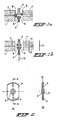
- Fig. 2 shows the charging electrode 3 in greater detail, in Fig. 2a the discharge channel 4 being indicated by dotted lines, while the bulge 5 is also indicated.
- Fig. 2b is a cross-section along the line A-A of Fig. 2a.
- the greatest dimension of the charging electrode 3 is, for example, 12 mm, while the greatest width is 8 mm.
- the circular bore has a dimension of 1 mm, while the bulge 5 has a diameter of approximately 2.4 mm.
- the channel 4 has a cross-section of 0.5 mm, while a fixing aperture 12 is also present, also with a cross-section of 0.5 mm.
- the bulge 5 has a bevel with an angle of 45° , while all sharp edges of the charging electrode are also broken.
- the charging electrode has a surface roughness of approximately 1.6 ru.
- FIG. 3a to 3d Various variants of the nozzle configuration according to the invention are shown in Figs. 3a to 3d.
- nozzle itself is provided with a bulge 1′, while the charging electrode is also provided with a bulge 6 at one side.
- nozzle and the deflection plates are provided with bulges 1′ and 7′ respectively.
- the nozzle is in the form of a capillary nozzle 1 ⁇ with a bulge which penetrates into the passage of the charging electrode 3; the deflection plates are also provided with a bulge 7′.
- a capillary outflow nozzle 1 ⁇ is also shown, in this case the charging electrode 3 being provided with a single bulge 6′.
- Fig. 4 shows a nozzle configuration of the type shown in Fig. 1; in the charging electrode there is, however, an additional feed channel 4′ for feeding into the passage of the charging electrode a protective fluid with low vapour tension and a good solvent action on the constituents of the ink to be used.
- air is first extracted for a short time through channel 4 for removal of following and/or imperfectly formed drops.
- a protective fluid can already be fed through the channel 4′, following which the extraction through channel 4 is ended and the infeed of protective fluid such as, for example, glycerol, N-methyl-pyrrolidone etc. is continued for some time yet until all critical narrow apertures are filled with the protective fluid.
- protective fluid such as, for example, glycerol, N-methyl-pyrrolidone etc.
- Fig. 5 shows an additional feed channel for protective fluid of a different shape, indicated by 4 ⁇ .
- the additional feed channel opens out at the side of the charging electrode 3 facing the drop-formation nozzle, and in particular the opening is provided above the passage of the charging electrode 3.
Landscapes
- Particle Formation And Scattering Control In Inkjet Printers (AREA)
- Nozzles (AREA)
- Ink Jet (AREA)
Abstract
Description
- The present invention relates to a nozzle configuration for forming, charging and deflecting ink drops in an ink-jet printer, comprising a drop-formation nozzle, a charging electrode provided with a passage, and deflection plates, the central axes of said parts lying in line with one another.
- Such a nozzle configuration is used in an ink-jet printer in order to charge drops which are formed under pressure, starting from a drop formation nozzle, while passing through the passage of a charging electrode, and subsequently to deflect them, through selective excitation of a set of deflection plates, depending on the final destination of a particular drop or series of drops. The nozzle configurations can also be designed in such a way that the drops are charged selectively through selective excitation of the charging electrode; the deflection plates are then connected to a constant deflection voltage.
- Such a known nozzle configuration shows problems in use which are largely due to blockages connected with pollution. Dried-up ink and dust collecting in the nozzle configuration can cause such problems, so that fault-free working of the nozzle configuration is not achieved.
- Attempts have been made through a suitable ink formulation to prevent blockages caused by solid material elements from the ink. In that case blockages can still occur through dust particles from the environment caking on the nozzle, the charging electrode and the deflection plates. The risk of pollution as a result of ink drops settling on the nozzle configuration occurs mainly during starting up and ending of operation of the ink-jet printer.
- Attempts have been made to provide solutions of a constructive nature to the problems described above. For example, an attempt was made to build into the pressure circuit of the drop-formation nozzle a quick-acting valve which opens only at relatively high pressure. The pressure in the nozzle is then built up in a relatively short time, which means that the time during which fluid comes out of the nozzle at low speed is reduced. The high-pressure pulse required for opening the quick-acting valve does, however, mean that there is a risk of damage to the nozzle and the valve itself, which is undesirable. The valve is also expensive, which adversely affects the price of the printer. In order to prevent pollution of the nozzle configuration, the passage in the charging electrode, which can be in the form of a bore or a slit, is often made much larger than is actually necessary to allow the jet through.
- Such a large dimension of the passage in the charging electrode is, however, a disadvantage because in that case extraneous electric fields can affect the charge, resulting in an undesirable deviation in the charging of the drops. In order to counter this effect, the length of the charging electrode, measured in the direction of the path of the drops, must incrase. Through such measures, there is, however, an increased risk of charged and uncharged drops merging, which can have an effect on the final sharpness of the image to be printed.
- In view of the last-mentioned considerations, a relatively small passage in the charging electrode and a small dimension measured in the drop path direction would be precisely what is required.
- Also, on account of the required overall space for arranging several nozzle configurations, it is very important to keep the dimensions of the various parts of the nozzle configuration as small as possbile, and to minimize the intervals between them.
- In that case the chance of pollution is, however, increased again.
- The object of the present invention is to provide a solution to the above-mentioned pollution problems, while at the same time providing a nozzle configuration with very small dimensions and distances between parts, which permits placing in an arrangement of great density.
- The nozzle configuration of the above-mentioned type is to this end according to the invention characterized in that the geometry and the placing of the drop-formation nozzle, the charging electrode and the deflection plates is selected in such a way that at least the unshielded interval directly adjacent to the path of the drops is a maximum of 0.1 - 2 mm and in the wall of the passage of the charging electrode there is a discharge aperture which connects to a channel which can be connected to extraction means.
- Through selecting the shape and the interval between the drop-formation nozzle, the charging electrode and the deflection plates in such a way that very small intervals are produced, the risk of pollution through penetrating ink and caking of dust is essentially increased. The intervals can be so small that there is even some capillary action. However, providing a discharge channel of small size in the wall of the passage in the charging electrode makes it possible at the start and finish of the operation of the nozzle configuration, as it were, to flush the configuration at low pressure while continuously discharging the ink fed out of the nozzle, which means that any caked ink residues and pollution are dissolved and discharged. During such a flushing operation, it is not necessary to excite the charging electrode and the deflection plates. After a sufficiently long flushing time, the extraction is then ended and, through simultaneous excitation of the various parts of the nozzle configuration, the operation of the ink-jet printer can begin.
- The various parts of the nozzle configuration need not be a short distance from the other parts over their entire surface; in particular, in the case of the nozzle configuration according to the invention, the drop-formation nozzle and/or the charging electrode and/or the deflection plates in the region adjacent to the aperture for permitting the passage of the drops is provided with a bulge whose wall adjacent to the aperture extends parallel to the central axis of the part in question.
- If such a bulge is present, the distance between the inside wall and the outside wall of the bulge will expediently be 0.1 to 2 mm. In the event of the passage in the charging electrode being a through bore, the bulge will therefore be of an annular type; if the passage is slit-shaped, the shape of the bulge will correspond thereto. In any case the width of the bulge will be 0.1 to 2 mm; such a dimension is not, however, critical.
- The discharge aperture present in the passage of the charging electrode and the channel connecting thereto can in general have a diameter in the range 0.1 to 1.0 mm, although again such a dimension is not critical. The channel connecting to the discharge aperture will be essentially at right angles to the direction of movement of the ink drops. The invention is also embodied in a nozzle configuration of the type described above according to the invention, which is incorporated, with or without a number of identical specimens, in an ink-jet printer which is known per se.
- The compact layout of the nozzle configuration according to the invention is an advantage in particular if several nozzles are inluded in an arrangement; due to the greatly reduced risk of pollution, the overall size of an arrangement can be kept very small.
- In order to obtain a better protection against drying-up of ink, an additional feed channel is advantageously present in the charging electrode for feeding in a medium which prevents ink from drying up. It has, in fact, been found that there are certain fluids with a very low vapour tension and with a good solvent action on the constituents of the ink which, when they are placed in the space between the drop-formation nozzle and the charging electrode and in the passage of the charging electrode, prevent drying-up of ink and dissolve any ink constituents left behind.
- In particular, when the operation of a nozzle configuration is stopped, the last action can be to feed through such a channel a small quantity of such a medium, which accumulates in the apertures between the various parts of the nozzle configuration and prevents drying-up there.
- When the nozzle configuration is started up again, ink can then be fed in, while at the same time the extraction through the channel takes place, so that the mixture of medium which prevents ink from drying up and ink itself is discharged directly thrugh the channel in the charging electrode.
- The additional feed channel can be provided in various ways; it can, for example, open out in the wall of the passage of the charging electrode, but it can also open out in the face of the charging electrode which faces the drop-formation nozzle, and in particular above the passage, so that medium fed in will go into the passage in all cases.
- The invention also relates to a process for operating a nozzle configuration of an ink-jet printer in which ink drops are released through the nozzle under pressure, these drops are selectively electrically charged, and the charged drops are deflected, characterized in that a nozzle configuration of the type described above according to the invention is used and on starting-up and/or stopping of the operation thereof medium conveyance takes place in the channels connecting to the charging electrode.
- In particular, with the use of the process according to the invention, at the starting and stopping of the nozzle configuration, air is extracted through the channel opening out in the passage of the charging electrode.
- Through this extraction, imperfectly formed drops are removed at the beginning or end of the operation.
- Through the same channel as that through which the extraction takes place, it is also possible to feed in a protective fluid when the operation of the nozzle configuration stops, and following the first extraction operation carried out for removal of imperfectly formed drops.
- The protective fluid can also be fed in through an additional feed channel which opens out either in the wall of the passage in the charging electrode or above the passage thereof in the wall of the charging electrode which faces the drop-formation nozle.
- The fluid used as the protective fluid will preferably have a low vapour tension and good solvent action on the constituents of the ink. Suitable fluids in that connection are polyalkylene glycols, alkylene glycols, lower alkyl ethers of alcohols, N-methyl-2-pyrrolidone, 1,3-dimethyl-2-imidazolidinone and mixtures of one or more of those fluids.
- The invention will now be explained with reference to the drawing, in which:
- - Figs. 1a and 1b show a nozzle configuration according to the invention in a polluted state and during the cleaning operation;
- - Figs. 2a and 2b show a charging electrode in a preferred embodiment;
- - Figs. 3a to d show a number of possible variants of a nozzle configuration according to the invention;
- - Fig. 4 shows a nozzle configuration of the type shown in Fig. 1, in which an additional feed channel is present;
- - Fig. 5 shows a nozzle configuration of the type shown in Fig. 4, with a feed channel of a different shape.
- In Fig. 1a a nozzle is shown shematically by 1, with an
ink feed channel 2. The ink is fed in under relatively high pressure to thechannel 2 and in the processs shows a tendency to form drops. During operation of the nozzle configuration the drops formed are charged in the passage of thecharging electrode 3, and the charged drops are then selectively deflected according to a predetermined programme between thedeflection plates 7, while the uncharged drops pass the deflection plates undeflected and arrive on the substrate.Reference numbers 8 and 9 indicate pollution which has accumulated in the narrow apertures, and which can be made up of dried-up ink, dust or other polluting material. In this case, the charging electrode is provided withbulges discharge channel 4 is present in the charging electrode. On starting-up of the configuration, ink is fed in through thenozzle 2, while the chargingelectrode 3 and thedeflection plates 7 are not excited. Air is extracted, by means not shown, through thechannel 4 which opens out in the discharge aperture in the chargingelectrode 3, for removal of the ink fed in under low pressure. The quantity of air passed through is not critical; a quantity between 0.5 and 16 litres per minute is suitable. On completion of the cleaning operation, theairstream 10 is stopped, and the chargingelectrode 3 and thedeflecton plates 7 are excited, and the substrate 11 to be printed is set in motion for the formation of a pattern which arises through selective excitation of the charging electrode and/or thedeflection plates 7. - Fig. 2 shows the charging
electrode 3 in greater detail, in Fig. 2a thedischarge channel 4 being indicated by dotted lines, while thebulge 5 is also indicated. Fig. 2b is a cross-section along the line A-A of Fig. 2a. In a specific embodiment the greatest dimension of the chargingelectrode 3 is, for example, 12 mm, while the greatest width is 8 mm. The circular bore has a dimension of 1 mm, while thebulge 5 has a diameter of approximately 2.4 mm. Thechannel 4 has a cross-section of 0.5 mm, while a fixing aperture 12 is also present, also with a cross-section of 0.5 mm. Thebulge 5 has a bevel with an angle of 45° , while all sharp edges of the charging electrode are also broken. - The charging electrode has a surface roughness of approximately 1.6 ru.
- Various variants of the nozzle configuration according to the invention are shown in Figs. 3a to 3d.
- In Fig. 3a the nozzle itself is provided with a bulge 1′, while the charging electrode is also provided with a
bulge 6 at one side. - In Fig. 3b the nozzle and the deflection plates are provided with bulges 1′ and 7′ respectively.
- In Fig. 3c the nozzle is in the form of a capillary nozzle 1˝ with a bulge which penetrates into the passage of the charging
electrode 3; the deflection plates are also provided with abulge 7′. - In Fig. 3d a capillary outflow nozzle 1˝ is also shown, in this case the charging
electrode 3 being provided with asingle bulge 6′. - The embodiments shown here are, of course, not all the embodiments which are possible within the scope of the invention; other embodiments are also conceivable for the expert.
- Fig. 4 shows a nozzle configuration of the type shown in Fig. 1; in the charging electrode there is, however, an
additional feed channel 4′ for feeding into the passage of the charging electrode a protective fluid with low vapour tension and a good solvent action on the constituents of the ink to be used. - Following the stoppage of the operation of the drop-formation nozzle, air is first extracted for a short time through
channel 4 for removal of following and/or imperfectly formed drops. During the above-mentioned extraction, a protective fluid can already be fed through thechannel 4′, following which the extraction throughchannel 4 is ended and the infeed of protective fluid such as, for example, glycerol, N-methyl-pyrrolidone etc. is continued for some time yet until all critical narrow apertures are filled with the protective fluid. When the nozzle configuration is started up again, a quantity of protective fluid is first removed by suction, and the drop-formation nozzle is then excited for the formation and delivery of ink drops. In the first instance, a mixture of protective fluid and ink is then removed, gradually becoming richer in ink until in the end pure ink is being discharged. The extraction throughchannel 4 is then ended, and normal operation of the nozzle configuration can take place. - Fig. 5 shows an additional feed channel for protective fluid of a different shape, indicated by 4˝. In this case the additional feed channel opens out at the side of the charging
electrode 3 facing the drop-formation nozzle, and in particular the opening is provided above the passage of the chargingelectrode 3.
Claims (15)
Priority Applications (1)
| Application Number | Priority Date | Filing Date | Title |
|---|---|---|---|
| AT90200736T ATE96737T1 (en) | 1989-03-28 | 1990-03-27 | NOZZLE ARRANGEMENT FOR COLOR JET PRINTER AND WORKING PROCESS. |
Applications Claiming Priority (2)
| Application Number | Priority Date | Filing Date | Title |
|---|---|---|---|
| NL8900760A NL8900760A (en) | 1989-03-28 | 1989-03-28 | NOZZLE CONFIGURATION FOR AN INK JET PRINTING DEVICE. |
| NL8900760 | 1989-03-28 |
Publications (2)
| Publication Number | Publication Date |
|---|---|
| EP0390283A1 true EP0390283A1 (en) | 1990-10-03 |
| EP0390283B1 EP0390283B1 (en) | 1993-11-03 |
Family
ID=19854370
Family Applications (1)
| Application Number | Title | Priority Date | Filing Date |
|---|---|---|---|
| EP90200736A Expired - Lifetime EP0390283B1 (en) | 1989-03-28 | 1990-03-27 | Nozzle configuration for an ink-jet printer and process for operating such a nozzle configuration |
Country Status (5)
| Country | Link |
|---|---|
| US (1) | US5142297A (en) |
| EP (1) | EP0390283B1 (en) |
| AT (1) | ATE96737T1 (en) |
| DE (1) | DE69004309T2 (en) |
| NL (1) | NL8900760A (en) |
Cited By (2)
| Publication number | Priority date | Publication date | Assignee | Title |
|---|---|---|---|---|
| WO2009068634A1 (en) * | 2007-11-29 | 2009-06-04 | Imaje S.A. | Ink jet print head with automated cleaning at the start of printing |
| US8955948B2 (en) | 2010-02-01 | 2015-02-17 | Markem-Imaje | Device forming a continuous inkjet printer cabinet with reduced concentrations of solvent vapor inside and around the cabinet |
Families Citing this family (6)
| Publication number | Priority date | Publication date | Assignee | Title |
|---|---|---|---|---|
| GB8829620D0 (en) * | 1988-12-20 | 1989-02-15 | Elmjet Ltd | Continuous ink jet printer |
| JP2840409B2 (en) * | 1990-08-24 | 1998-12-24 | キヤノン株式会社 | Ink jet recording head and ink jet recording apparatus |
| US5577091A (en) * | 1994-04-01 | 1996-11-19 | University Of Central Florida | Water laser plasma x-ray point sources |
| US5459771A (en) * | 1994-04-01 | 1995-10-17 | University Of Central Florida | Water laser plasma x-ray point source and apparatus |
| US6831963B2 (en) | 2000-10-20 | 2004-12-14 | University Of Central Florida | EUV, XUV, and X-Ray wavelength sources created from laser plasma produced from liquid metal solutions |
| GB0701233D0 (en) * | 2007-01-23 | 2007-02-28 | Videojet Technologies Inc | A continuous stream ink jet print head |
Citations (1)
| Publication number | Priority date | Publication date | Assignee | Title |
|---|---|---|---|---|
| US4288796A (en) * | 1977-06-27 | 1981-09-08 | Sharp Kabushiki Kaisha | Phase detection in an ink jet system printer of the charge amplitude controlling type |
Family Cites Families (3)
| Publication number | Priority date | Publication date | Assignee | Title |
|---|---|---|---|---|
| SE342334B (en) * | 1969-04-02 | 1972-01-31 | C Hertz | |
| GB8810241D0 (en) * | 1988-04-29 | 1988-06-02 | Am Int | Drop-on-demand printhead |
| US4928113A (en) * | 1988-10-31 | 1990-05-22 | Eastman Kodak Company | Constructions and fabrication methods for drop charge/deflection in continuous ink jet printer |
-
1989
- 1989-03-28 NL NL8900760A patent/NL8900760A/en not_active Application Discontinuation
-
1990
- 1990-03-26 US US07/499,175 patent/US5142297A/en not_active Expired - Fee Related
- 1990-03-27 AT AT90200736T patent/ATE96737T1/en not_active IP Right Cessation
- 1990-03-27 DE DE90200736T patent/DE69004309T2/en not_active Expired - Fee Related
- 1990-03-27 EP EP90200736A patent/EP0390283B1/en not_active Expired - Lifetime
Patent Citations (1)
| Publication number | Priority date | Publication date | Assignee | Title |
|---|---|---|---|---|
| US4288796A (en) * | 1977-06-27 | 1981-09-08 | Sharp Kabushiki Kaisha | Phase detection in an ink jet system printer of the charge amplitude controlling type |
Non-Patent Citations (5)
| Title |
|---|
| IBM TECHNICAL DISCLOSURE BULLETIN. vol. 19, no. 11, April 1977, NEW YORK US page 4399 R.H. Darling: "Vacuum-cleaned charge electrodes." * |
| PATENT ABSTRACTS OF JAPAN vol. 2, no. 147 (E-78) 08 December 78, & JP-A-53 115224 (M. MATSUMOTO) 10 July 1978, * |
| PATENT ABSTRACTS OF JAPAN vol. 4, no. 114 (M-26)(596) 15 August 1980, & JP-A-55 71577 (S. KAKEFU) 29 May 1980, * |
| PATENT ABSTRACTS OF JAPAN vol. 6, no. 76 (M-128)(954) 13 May 1982, & JP-A-57 15972 (M. KIKUCHI) 27 January 1982, * |
| PATENT ABSTRACTS OF JAPAN vol. 7, no. 79 (M-204)(1224) 31 March 1983, & JP-A-58 5262 (M. KAWAI) 12 January 1983, * |
Cited By (3)
| Publication number | Priority date | Publication date | Assignee | Title |
|---|---|---|---|---|
| WO2009068634A1 (en) * | 2007-11-29 | 2009-06-04 | Imaje S.A. | Ink jet print head with automated cleaning at the start of printing |
| FR2924379A1 (en) * | 2007-11-29 | 2009-06-05 | Imaje Sa Sa | INKJET PRINTING HEAD WITH AUTOMATED CLEANING AT PRINT START |
| US8955948B2 (en) | 2010-02-01 | 2015-02-17 | Markem-Imaje | Device forming a continuous inkjet printer cabinet with reduced concentrations of solvent vapor inside and around the cabinet |
Also Published As
| Publication number | Publication date |
|---|---|
| DE69004309T2 (en) | 1994-02-24 |
| NL8900760A (en) | 1990-10-16 |
| EP0390283B1 (en) | 1993-11-03 |
| DE69004309D1 (en) | 1993-12-09 |
| US5142297A (en) | 1992-08-25 |
| ATE96737T1 (en) | 1993-11-15 |
Similar Documents
| Publication | Publication Date | Title |
|---|---|---|
| DE69807488T2 (en) | BUILT-IN CLEANING DEVICE FOR AN INK JET PRINT HEAD | |
| US4959662A (en) | Ink jet recorder having means for removing unused ink from ink discharge orifice and for capping same | |
| DE60034508T2 (en) | CLEANING OF INJECTOR HEAD PRESSURE HEADS WITH MULTIPLE LIQUIDS | |
| US4160982A (en) | Anti-dispersion accumulator for ink jet printing system | |
| JP2022132443A (en) | Inkjet recording device | |
| US11760096B2 (en) | Method and device for maintaining a nozzle print head | |
| EP0390283B1 (en) | Nozzle configuration for an ink-jet printer and process for operating such a nozzle configuration | |
| US6511151B1 (en) | Ink jet printer and cleaning blade and method of cleaning | |
| JPS5835150B2 (en) | ink | |
| US4623897A (en) | Ink jet air-skiving start-up system | |
| WO1993017867A1 (en) | Method for flushing an ink flow system | |
| CN100478182C (en) | Continuous ink jet printer cleaning system, self-cleaning printing head and cleaning method | |
| US4023182A (en) | Vacuum return system for ink jet printing apparatus | |
| KR20180098568A (en) | Maintenance device of inkjet head and method of maintenance of inkjet head | |
| DE2926869A1 (en) | INK-RAY COLLECTION SYSTEM | |
| US10836163B2 (en) | Print head of an ink jet printer with 2 gutters for recovery, of which one is mobile | |
| DE69622958T2 (en) | Electrostatic ink jet head | |
| WO1998006583A1 (en) | Ink jet printer | |
| US10994537B2 (en) | Method and device for detecting the correct operation of the nozzles of a print head | |
| JP7066859B2 (en) | Inkjet recording device | |
| JP2021091176A (en) | Inkjet recording device | |
| US20240326101A1 (en) | Method and apparatus for cleaning carrier film | |
| CN112440578A (en) | System and method for cleaning a printhead | |
| DE2512744B2 (en) | Dust protection for the ink jet head in particular in an ink jet writing mechanism | |
| WO2025257576A1 (en) | Printer and associated method |
Legal Events
| Date | Code | Title | Description |
|---|---|---|---|
| PUAI | Public reference made under article 153(3) epc to a published international application that has entered the european phase |
Free format text: ORIGINAL CODE: 0009012 |
|
| AK | Designated contracting states |
Kind code of ref document: A1 Designated state(s): AT BE CH DE DK ES FR GB GR IT LI LU NL SE |
|
| 17P | Request for examination filed |
Effective date: 19901211 |
|
| 17Q | First examination report despatched |
Effective date: 19920707 |
|
| RAP1 | Party data changed (applicant data changed or rights of an application transferred) |
Owner name: STORK COLORPROOFING B.V. |
|
| GRAA | (expected) grant |
Free format text: ORIGINAL CODE: 0009210 |
|
| AK | Designated contracting states |
Kind code of ref document: B1 Designated state(s): AT BE CH DE DK ES FR GB GR IT LI LU NL SE |
|
| PG25 | Lapsed in a contracting state [announced via postgrant information from national office to epo] |
Ref country code: GR Free format text: LAPSE BECAUSE OF FAILURE TO SUBMIT A TRANSLATION OF THE DESCRIPTION OR TO PAY THE FEE WITHIN THE PRESCRIBED TIME-LIMIT Effective date: 19931103 Ref country code: ES Free format text: THE PATENT HAS BEEN ANNULLED BY A DECISION OF A NATIONAL AUTHORITY Effective date: 19931103 Ref country code: DK Effective date: 19931103 Ref country code: AT Effective date: 19931103 |
|
| REF | Corresponds to: |
Ref document number: 96737 Country of ref document: AT Date of ref document: 19931115 Kind code of ref document: T |
|
| REF | Corresponds to: |
Ref document number: 69004309 Country of ref document: DE Date of ref document: 19931209 |
|
| ET | Fr: translation filed | ||
| ITF | It: translation for a ep patent filed | ||
| PG25 | Lapsed in a contracting state [announced via postgrant information from national office to epo] |
Ref country code: LU Free format text: LAPSE BECAUSE OF NON-PAYMENT OF DUE FEES Effective date: 19940331 |
|
| PLBE | No opposition filed within time limit |
Free format text: ORIGINAL CODE: 0009261 |
|
| STAA | Information on the status of an ep patent application or granted ep patent |
Free format text: STATUS: NO OPPOSITION FILED WITHIN TIME LIMIT |
|
| 26N | No opposition filed | ||
| EAL | Se: european patent in force in sweden |
Ref document number: 90200736.8 |
|
| REG | Reference to a national code |
Ref country code: GB Ref legal event code: IF02 |
|
| PGFP | Annual fee paid to national office [announced via postgrant information from national office to epo] |
Ref country code: SE Payment date: 20020322 Year of fee payment: 13 Ref country code: GB Payment date: 20020322 Year of fee payment: 13 Ref country code: FR Payment date: 20020322 Year of fee payment: 13 Ref country code: DE Payment date: 20020322 Year of fee payment: 13 |
|
| PGFP | Annual fee paid to national office [announced via postgrant information from national office to epo] |
Ref country code: BE Payment date: 20020325 Year of fee payment: 13 |
|
| PGFP | Annual fee paid to national office [announced via postgrant information from national office to epo] |
Ref country code: NL Payment date: 20020329 Year of fee payment: 13 |
|
| PGFP | Annual fee paid to national office [announced via postgrant information from national office to epo] |
Ref country code: CH Payment date: 20020417 Year of fee payment: 13 |
|
| PG25 | Lapsed in a contracting state [announced via postgrant information from national office to epo] |
Ref country code: GB Free format text: LAPSE BECAUSE OF NON-PAYMENT OF DUE FEES Effective date: 20030327 |
|
| PG25 | Lapsed in a contracting state [announced via postgrant information from national office to epo] |
Ref country code: SE Free format text: LAPSE BECAUSE OF NON-PAYMENT OF DUE FEES Effective date: 20030328 |
|
| PG25 | Lapsed in a contracting state [announced via postgrant information from national office to epo] |
Ref country code: LI Free format text: LAPSE BECAUSE OF NON-PAYMENT OF DUE FEES Effective date: 20030331 Ref country code: CH Free format text: LAPSE BECAUSE OF NON-PAYMENT OF DUE FEES Effective date: 20030331 Ref country code: BE Free format text: LAPSE BECAUSE OF NON-PAYMENT OF DUE FEES Effective date: 20030331 |
|
| BERE | Be: lapsed |
Owner name: *STORK COLORPROOFING B.V. Effective date: 20030331 |
|
| PG25 | Lapsed in a contracting state [announced via postgrant information from national office to epo] |
Ref country code: NL Free format text: LAPSE BECAUSE OF NON-PAYMENT OF DUE FEES Effective date: 20031001 Ref country code: DE Free format text: LAPSE BECAUSE OF NON-PAYMENT OF DUE FEES Effective date: 20031001 |
|
| EUG | Se: european patent has lapsed | ||
| REG | Reference to a national code |
Ref country code: CH Ref legal event code: PL |
|
| GBPC | Gb: european patent ceased through non-payment of renewal fee |
Effective date: 20030327 |
|
| PG25 | Lapsed in a contracting state [announced via postgrant information from national office to epo] |
Ref country code: FR Free format text: LAPSE BECAUSE OF NON-PAYMENT OF DUE FEES Effective date: 20031127 |
|
| NLV4 | Nl: lapsed or anulled due to non-payment of the annual fee |
Effective date: 20031001 |
|
| REG | Reference to a national code |
Ref country code: FR Ref legal event code: ST |
|
| PG25 | Lapsed in a contracting state [announced via postgrant information from national office to epo] |
Ref country code: IT Free format text: LAPSE BECAUSE OF NON-PAYMENT OF DUE FEES;WARNING: LAPSES OF ITALIAN PATENTS WITH EFFECTIVE DATE BEFORE 2007 MAY HAVE OCCURRED AT ANY TIME BEFORE 2007. THE CORRECT EFFECTIVE DATE MAY BE DIFFERENT FROM THE ONE RECORDED. Effective date: 20050327 |