EP0390045A2 - Shelf-support bracket - Google Patents
Shelf-support bracket Download PDFInfo
- Publication number
- EP0390045A2 EP0390045A2 EP90105732A EP90105732A EP0390045A2 EP 0390045 A2 EP0390045 A2 EP 0390045A2 EP 90105732 A EP90105732 A EP 90105732A EP 90105732 A EP90105732 A EP 90105732A EP 0390045 A2 EP0390045 A2 EP 0390045A2
- Authority
- EP
- European Patent Office
- Prior art keywords
- wall
- adjuster
- bracket
- insert
- shelf
- Prior art date
- Legal status (The legal status is an assumption and is not a legal conclusion. Google has not performed a legal analysis and makes no representation as to the accuracy of the status listed.)
- Granted
Links
Images




Classifications
-
- A—HUMAN NECESSITIES
- A47—FURNITURE; DOMESTIC ARTICLES OR APPLIANCES; COFFEE MILLS; SPICE MILLS; SUCTION CLEANERS IN GENERAL
- A47B—TABLES; DESKS; OFFICE FURNITURE; CABINETS; DRAWERS; GENERAL DETAILS OF FURNITURE
- A47B96/00—Details of cabinets, racks or shelf units not covered by a single one of groups A47B43/00 - A47B95/00; General details of furniture
- A47B96/06—Brackets or similar supporting means for cabinets, racks or shelves
- A47B96/063—C-shaped brackets for gripping the shelf edge
- A47B96/065—C-shaped brackets for gripping the shelf edge adjustable to the thickness of the shelf
-
- A—HUMAN NECESSITIES
- A47—FURNITURE; DOMESTIC ARTICLES OR APPLIANCES; COFFEE MILLS; SPICE MILLS; SUCTION CLEANERS IN GENERAL
- A47B—TABLES; DESKS; OFFICE FURNITURE; CABINETS; DRAWERS; GENERAL DETAILS OF FURNITURE
- A47B96/00—Details of cabinets, racks or shelf units not covered by a single one of groups A47B43/00 - A47B95/00; General details of furniture
- A47B96/02—Shelves
- A47B96/027—Cantilever shelves
Definitions
- This invention relates to shelf-support brackets, and particularly such brackets which are attachable to display fixtures.
- Shelf support brackets are typically used in retail or other merchandise outlet stores, and releasably attached to a display fixture on a wall.
- the support bracket may include a lip which is receivable within a channel on the display fixture. With the shelf support bracket firmly attached to the display fixture, a shelf is inserted in the shelf support bracket, so as to provide a cantilever shelf support. Various articles of merchandise may thereafter be placed on the shelf support for simple and attractive display.
- the shelf-support bracket would incorporate substantially parallel top and lower surfaces which define a space in which the shelf is received.
- Each support bracket would have top and lower surfaces which are a fixed distance apart, and which are specifically adapted for receiving a shelf of specific thickness.
- a support bracket comprising a support wall; an upper wall extending substantially transversely to the support wall, the upper wall having a lower surface; a lower wall fixed near an end thereof to the support wall and being substantially parallel to the upper horizontal wall, the lower wall having an upper surface, the upper and lower walls defining therebetween a space which, in use, receives a shelf which is supported by the upper and lower walls respectively in cantilever fashion; track means in the lower surface of the upper horizontal wall and the upper surface of the lower horizontal wall; adjuster insert means for use in cooperation with the track means, the adjuster insert means having a tracking portion which registers with the track means to securely hold the adjuster insert means relative to the upper and lower walls respectively, the adjuster insert means permitting shelves of differing thickness to be received in the space.
- the bracket comprises a suspension lip affixed to the support wall, the suspension lip, in use, attaching to a display fixture, and having a portion substantially continuous with the upper wall, and projecting flange.
- the track means in the lower surface of the upper wall and the upper surface of the lower wall are located in the upper and lower wall respectively at a location thereon remote from the support wall.
- the track means may comprise a recess in the wall, the recess extending across the wall, the recess including a projection therein dividing the recess into two parallel channeled grooves.
- the projection is eccentrically located in the recess thereby dividing the recess into a wide channel groove and a narrow channel groove.
- the adjuster insert means may be an elongate body of substantially rectangular cross-section with a long side and a short side, the adjuster insert means having a slot along each of the long side and short side thereof, the slot being adapted, in use, to accommodate the projection in the recess, whereby the adjuster insert can be arranged in two positions with respect to the track means, the first position comprising the slot in the long side of the adjustor insert receiving the projection, the second position comprising the slot in the short side of the adjuster insert receiving the projection.
- the adjuster insert means has one or more of its surfaces comprised of a series of ridges, the ridges on the surface of one insert adjuster means engaging spaces between the ridges on a second insert adjuster means wherein when two adjuster means are placed adjacent each other, the ridges engage preventing slippage or movement between the adjacent adjuster means.
- the support wall has a rear surface, and further track means are provided in the rear surface, the track means being adapted to receive adjuster insert means having a tracking portion which registers with the track means.
- the track means in the rear surface of the vertical wall are located at or near a lower end of the vertical wall.
- a method of supporting a cantilever shelf with a bracket comprising providing a shelf support bracket having a support wall, an upper wall and a lower wall both fixed to the support wall and immovable relative thereto, the upper and lower walls defining a space of fixed dimension therebetween for accommodating a shelf; providing tracking means in a lower surface of the upper wall and an upper surface of the lower wall; inserting an adjuster insert means in one or more of the track means in the space defined between the upper and lower walls so that shelves of varying thicknesses can be accommodated therein according to the mode of use of such adjuster insert means and the number thereof used.
- each horizontal channel comprises a mouth portion or slot 18 leading into a rectangular chamber portion 20.
- the channel 16 is preferably lined with a plastic or aluminum extruded insert 22 to prevent wear of those portions of the display fixture 12 which border the horizontal channels 16.
- the shelf support bracket 10 comprises a rear vertical wall 24, an upper horizontal wall 26, and a lower horizontal wall 28.
- the upper horizontal wall 26 is located at the top of the rear vertical wall 24, while the lower horizontal wall 28 extends outwardly from the rear vertical wall 24 approximately one third of the way down its length.
- the upper and lower horizontal walls 26 and 28 define therebetween a rectangular space 30 which is adapted to receive a shelf 32, to be described in greater detail hereunder.
- a support wall 34 extends between the outer end 36 of the lower horizontal wall 28 and the lower end 38 of the rear vertical wall 24. In this way, additional support is provided to the lower horizontal wall, which is thus well adapted to support in cantilever fashion a shelf 32, as well as any merchandise or articles which may be placed thereon.
- a suspension lip 40 is also provided at the upper end of the vertical wall 24.
- the lip 40 comprises a horizontal portion 42 and a vertical flange 44.
- the vertical flange is adapted to pass through the mouth portion or slot 18 of the horizontal channel 16 for location in the rectangular chamber portion 20.
- the horizontal portion 42 extends, when the bracket is attached to the wall 14, through the mouth portion or slot 18.
- An aperture 46 is provided in the vertical flange 44, so that the bracket 10 may be more permanently affixed to the display fixture by driving a nail or screw through the aperture 46 between the bracket 10 and the display fixture 12.
- Tracking grooves 48 are positioned on the shelf support bracket 10 at various locations.
- a tracking groove 48a is located on the undersurface 50 of the upper horizontal wall 26
- tracking groove 48b is located on the upper surface 52 of the lower horizontal wall 28
- tracking groove 48c is located on the rear surface 54 of the vertical wall 24.
- Each tracking groove 48 comprises a recess 56 having a projection 58 therein. The projection 58 is not centrally located within the recess 56, and divides the recess 56 into a wide groove 60 and a narrow groove 62.
- tracks 48 run across the entire width of the bracket 10 at their respective locations.
- the shelf support bracket 10 further comprises a shelf adjuster insert 64, an insert optionally being used with each set of tracks 48.
- the shelf adjuster insert 64 is substantially rectangular in cross section, and is constructed for use with a track 48.
- Each adjuster insert 64 has a short side 66 and a long side 68.
- a first slot 70 is fashioned in the adjuster insert so as to open along one short side 66 thereof, while a second slot 72 is fashioned in the long side 68 of the adjuster insert and is open at the long side 68.
- One or more sides of the adjuster insert 64 may be knurled, and in the presently shown embodiment in Figure 7, two sides (a long side and a short side) have such a knurled configuration.
- a shelf adjuster insert 64 may be used with any one or more of the tracks 48a, 48b, 48c.
- the adjuster insert 64 may be positioned with respect to each track 48 in two ways. In a first position, the adjuster insert 64 may be located in the track 48 such that the projection 58 extends into the second slot 72, with the arm 74 being located in the narrow groove 62 and a portion of the long side 68 being positioned in the wide groove 60. In a second position, the adjuster insert 64 may be positioned in any one of the tracks 48 whereby the projection 58 extends into the first slot 70, with the arms 76 and 78 straddling the projection 58.
- the shelf support bracket 10, used in combination with one or more shelf adjuster inserts 64, is readily adaptable for use with shelves 32 of differing thicknesses, and appropriate use of the inserts 64 can result in the shelf 32 being mounted at different angles, which may be conveniently selected depending upon the merchandise or display items to be located on the shelf 32.
- the thickest shelf 32 can be accommodated in the space 30 with no shelf adjuster inserts in place.
- the space 30 can be progressively narrowed.
- an adjuster insert 64 may be located in either the first or second position in the track 48b.
- an adjuster insert 64 may be located in track 48a in a first position, and an adjuster insert 64 in track 48b in either the first or second position.
- an adjuster insert 64 may be located in the second position in the track 48a, with a further adjuster insert 64 located in track 48b in either the first or second position.
- shelves of seven different thicknesses may be located in a single bracket in the space 30 according to the use and configuration of adjuster inserts 64 in either of the tracks 48a and 48b.
- the thickness defined by the space 30 may thus be adjusted to be bigger or smaller in small increments, and the expense of providing a different size bracket for a particular thickness shelf is obviated.
- the large number of thicknesses can be provided with only a single size and shape shelf adjuster insert 64.
- the fine adjustment of the angle and tilt of the shelf 32 may further be varied, as set forth above, by location of a shelf adjuster insert 64 in the track 48c.
- a shelf adjuster insert 64 in the track 48c. The use and effect of an insert within the track 48c has already been described above.
- the space 30 may be further narrowed in addition to the methods described above by placing a first shelf adjuster insert 64 in the track 48b, and placing a second adjuster insert on top of the first insert such that knurled surfaces of the adjuster insert are in contact with each other and thereby prevent slippage of the first insert with respect to the second insert.
- a similar arrangement can be used in the track 48a, although it will be appreciated that a second insert 64 requires the upward pressure of the shelf 32 to hold it against the first insert 64 located in the track 48a.
- the shelf 32 would in any event have an upward force due to the cantilever arrangement thereof, more than one insert 64 may be used with respect to the track 48a.
- each insert may be in either the first or second position.
- any one or more of the tracks 48a and 48b can produce a very large number of space 30 adjustments whereby the space 30 can accommodate shelves 32 of varying thicknesses.
- the bracket is thus extremely versatile and has a wide application in that only a single bracket is necessary for shelves whose thickness may vary considerably. Since the shelf is supported in cantilever fashion in the space 30, there will be an upward force from the shelf at the track 48a, and a downward force by the shelf at the track 48b, and these forces will securely hold one or more shelf adjuster inserts in position over the tracks.
- tracks 48 need not be provided in both the undersurface 50 of the upper horizontal wall 26 and the upper surface 52 of the lower horizontal wall 28. Only one such track need be provided. Additionally, the track 48c may be omitted.
- any suitable shape shelf adjuster insert may be provided to meet the requirements for narrowing the space 30 above. Further, the tracks 48a and 48b may be located at different points along the undersurface 50 and upper surface 52 of the upper and lower horizontal walls 26 and 28 respectively.
Landscapes
- Display Racks (AREA)
- Assembled Shelves (AREA)
- Legs For Furniture In General (AREA)
Abstract
Description
- This invention relates to shelf-support brackets, and particularly such brackets which are attachable to display fixtures.
- Shelf support brackets are typically used in retail or other merchandise outlet stores, and releasably attached to a display fixture on a wall. The support bracket may include a lip which is receivable within a channel on the display fixture. With the shelf support bracket firmly attached to the display fixture, a shelf is inserted in the shelf support bracket, so as to provide a cantilever shelf support. Various articles of merchandise may thereafter be placed on the shelf support for simple and attractive display.
- Typically, the shelf-support bracket would incorporate substantially parallel top and lower surfaces which define a space in which the shelf is received. Each support bracket would have top and lower surfaces which are a fixed distance apart, and which are specifically adapted for receiving a shelf of specific thickness.
- According to one aspect of the invention, there is provided a support bracket comprising a support wall; an upper wall extending substantially transversely to the support wall, the upper wall having a lower surface; a lower wall fixed near an end thereof to the support wall and being substantially parallel to the upper horizontal wall, the lower wall having an upper surface, the upper and lower walls defining therebetween a space which, in use, receives a shelf which is supported by the upper and lower walls respectively in cantilever fashion; track means in the lower surface of the upper horizontal wall and the upper surface of the lower horizontal wall; adjuster insert means for use in cooperation with the track means, the adjuster insert means having a tracking portion which registers with the track means to securely hold the adjuster insert means relative to the upper and lower walls respectively, the adjuster insert means permitting shelves of differing thickness to be received in the space.
- Preferably, the bracket comprises a suspension lip affixed to the support wall, the suspension lip, in use, attaching to a display fixture, and having a portion substantially continuous with the upper wall, and projecting flange.
- Conveniently, the track means in the lower surface of the upper wall and the upper surface of the lower wall are located in the upper and lower wall respectively at a location thereon remote from the support wall. The track means may comprise a recess in the wall, the recess extending across the wall, the recess including a projection therein dividing the recess into two parallel channeled grooves. Preferably, the projection is eccentrically located in the recess thereby dividing the recess into a wide channel groove and a narrow channel groove.
- The adjuster insert means may be an elongate body of substantially rectangular cross-section with a long side and a short side, the adjuster insert means having a slot along each of the long side and short side thereof, the slot being adapted, in use, to accommodate the projection in the recess, whereby the adjuster insert can be arranged in two positions with respect to the track means, the first position comprising the slot in the long side of the adjustor insert receiving the projection, the second position comprising the slot in the short side of the adjuster insert receiving the projection. Preferably, the adjuster insert means has one or more of its surfaces comprised of a series of ridges, the ridges on the surface of one insert adjuster means engaging spaces between the ridges on a second insert adjuster means wherein when two adjuster means are placed adjacent each other, the ridges engage preventing slippage or movement between the adjacent adjuster means.
- Preferably, the support wall has a rear surface, and further track means are provided in the rear surface, the track means being adapted to receive adjuster insert means having a tracking portion which registers with the track means. The track means in the rear surface of the vertical wall are located at or near a lower end of the vertical wall.
- According to another aspect of the invention, there is provided a method of supporting a cantilever shelf with a bracket, the method comprising providing a shelf support bracket having a support wall, an upper wall and a lower wall both fixed to the support wall and immovable relative thereto, the upper and lower walls defining a space of fixed dimension therebetween for accommodating a shelf; providing tracking means in a lower surface of the upper wall and an upper surface of the lower wall; inserting an adjuster insert means in one or more of the track means in the space defined between the upper and lower walls so that shelves of varying thicknesses can be accommodated therein according to the mode of use of such adjuster insert means and the number thereof used.
-
- Figure 1 is a perspective view of a shelf support bracket of the invention.
- Figure 2 is a perspective view of a display fixture for use with the bracket.
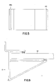
- Figure 3 is a side view of the shelf support bracket shown in Figure 1.
- Figure 4 is a front view of the shelf support bracket shown in Figure 1.
- Figure 5 is a top view of the shelf support bracket shown in Figure 1.
- Figure 6 is a perspective view of a bracket attached to a display fixture.
- Figure 7 is a perspective view of a shelf adjuster insert for use with the shelf support bracket shown in Figure 1.
- Figure 8 is a perspective view of a bracket, shelf and adjuster inserts of the invention.
- Figure 9 is a side view of a bracket, shelf and adjuster means of the invention.
- With reference to the drawings, there is shown a preferred embodiment of the invention, comprising a shelf support bracket which may be fixed to a
display fixture 12, thedisplay fixture 12 typically being attached to or forming awall 14 and having a series ofhorizontal channels 16 spaced thereover. In the present embodiment, each horizontal channel comprises a mouth portion orslot 18 leading into arectangular chamber portion 20. Thechannel 16 is preferably lined with a plastic or aluminum extrudedinsert 22 to prevent wear of those portions of thedisplay fixture 12 which border thehorizontal channels 16. - The
shelf support bracket 10 comprises a rearvertical wall 24, an upperhorizontal wall 26, and a lowerhorizontal wall 28. The upperhorizontal wall 26 is located at the top of the rearvertical wall 24, while the lowerhorizontal wall 28 extends outwardly from the rearvertical wall 24 approximately one third of the way down its length. The upper and lowerhorizontal walls rectangular space 30 which is adapted to receive ashelf 32, to be described in greater detail hereunder. - A
support wall 34 extends between theouter end 36 of the lowerhorizontal wall 28 and thelower end 38 of the rearvertical wall 24. In this way, additional support is provided to the lower horizontal wall, which is thus well adapted to support in cantilever fashion ashelf 32, as well as any merchandise or articles which may be placed thereon. - A
suspension lip 40 is also provided at the upper end of thevertical wall 24. Thelip 40 comprises ahorizontal portion 42 and avertical flange 44. In use, the vertical flange is adapted to pass through the mouth portion orslot 18 of thehorizontal channel 16 for location in therectangular chamber portion 20. Thehorizontal portion 42 extends, when the bracket is attached to thewall 14, through the mouth portion orslot 18. Anaperture 46 is provided in thevertical flange 44, so that thebracket 10 may be more permanently affixed to the display fixture by driving a nail or screw through theaperture 46 between thebracket 10 and thedisplay fixture 12. - Tracking grooves 48 are positioned on the
shelf support bracket 10 at various locations. Atracking groove 48a is located on theundersurface 50 of the upperhorizontal wall 26,tracking groove 48b is located on theupper surface 52 of the lowerhorizontal wall 28 andtracking groove 48c is located on therear surface 54 of thevertical wall 24. Each tracking groove 48 comprises arecess 56 having aprojection 58 therein. Theprojection 58 is not centrally located within therecess 56, and divides therecess 56 into awide groove 60 and anarrow groove 62. - It will be noted that the tracks 48 run across the entire width of the
bracket 10 at their respective locations. - The
shelf support bracket 10 further comprises ashelf adjuster insert 64, an insert optionally being used with each set of tracks 48. Theshelf adjuster insert 64 is substantially rectangular in cross section, and is constructed for use with a track 48. - Each
adjuster insert 64 has ashort side 66 and along side 68. Afirst slot 70 is fashioned in the adjuster insert so as to open along oneshort side 66 thereof, while asecond slot 72 is fashioned in thelong side 68 of the adjuster insert and is open at thelong side 68. One or more sides of theadjuster insert 64 may be knurled, and in the presently shown embodiment in Figure 7, two sides (a long side and a short side) have such a knurled configuration. - In use, a
shelf adjuster insert 64 may be used with any one or more of thetracks adjuster insert 64 may be positioned with respect to each track 48 in two ways. In a first position, theadjuster insert 64 may be located in the track 48 such that theprojection 58 extends into thesecond slot 72, with thearm 74 being located in thenarrow groove 62 and a portion of thelong side 68 being positioned in thewide groove 60. In a second position, theadjuster insert 64 may be positioned in any one of the tracks 48 whereby theprojection 58 extends into thefirst slot 70, with thearms projection 58. - With respect to the
tracks space 30 by different amounts. Thus, thespace 30 will be narrower when anadjuster insert 64 is located in thetrack 48b in the second position, than when theadjuster insert 64 is located in thetrack 48b in the first position. A similar situation would prevail with respect to location of an adjuster insert 64 in thetrack 48a. - Turning to the
track 48c, at thelower end 38 of the rearvertical wall 24, positioning of an adjuster insert 64 therein in either the first or second position will have the effect of distancing thelower end 38 of the rear vertical wall from thedisplay fixture 12 by different amounts. If nosuch adjuster insert 64 is positioned in thetrack 48c, the rearvertical wall 24 will typically lie adjacent thedisplay fixture 12. Where theadjuster insert 64 is inserted in thetrack 48c in either the first or second position, the rear vertical wall will be moved away from thedisplay fixture 12, and the effect will be that theentire bracket 10 will be slightly tilted with respect to the display fixture. It will be appreciated that tilting of thebracket 10 results in an adjustment of the angle of ashelf 32 in thespace 30. - The
shelf support bracket 10, used in combination with one or moreshelf adjuster inserts 64, is readily adaptable for use withshelves 32 of differing thicknesses, and appropriate use of theinserts 64 can result in theshelf 32 being mounted at different angles, which may be conveniently selected depending upon the merchandise or display items to be located on theshelf 32. - With respect to a particular
shelf support bracket 10, thethickest shelf 32 can be accommodated in thespace 30 with no shelf adjuster inserts in place. Using a single shelf adjuster insert, thespace 30 can be progressively narrowed. Thus, there may be an absence of ashelf adjuster insert 64 intrack 48a, but anadjuster insert 64 may be located in either the first or second position in thetrack 48b. Alternatively, anadjuster insert 64 may be located intrack 48a in a first position, and anadjuster insert 64 intrack 48b in either the first or second position. Finally, anadjuster insert 64 may be located in the second position in thetrack 48a, with afurther adjuster insert 64 located intrack 48b in either the first or second position. Using this technique alone, it will be noted that shelves of seven different thicknesses may be located in a single bracket in thespace 30 according to the use and configuration of adjuster inserts 64 in either of thetracks space 30 may thus be adjusted to be bigger or smaller in small increments, and the expense of providing a different size bracket for a particular thickness shelf is obviated. Further, it will also be noted that the large number of thicknesses can be provided with only a single size and shapeshelf adjuster insert 64. - The fine adjustment of the angle and tilt of the
shelf 32 may further be varied, as set forth above, by location of ashelf adjuster insert 64 in thetrack 48c. The use and effect of an insert within thetrack 48c has already been described above. - It is also to be noted that the
space 30 may be further narrowed in addition to the methods described above by placing a firstshelf adjuster insert 64 in thetrack 48b, and placing a second adjuster insert on top of the first insert such that knurled surfaces of the adjuster insert are in contact with each other and thereby prevent slippage of the first insert with respect to the second insert. A similar arrangement can be used in thetrack 48a, although it will be appreciated that asecond insert 64 requires the upward pressure of theshelf 32 to hold it against thefirst insert 64 located in thetrack 48a. However, since theshelf 32 would in any event have an upward force due to the cantilever arrangement thereof, more than oneinsert 64 may be used with respect to thetrack 48a. Also, each insert may be in either the first or second position. - Thus, using no, one, or two inserts with respect to any one or more of the
tracks space 30 adjustments whereby thespace 30 can accommodateshelves 32 of varying thicknesses. The bracket is thus extremely versatile and has a wide application in that only a single bracket is necessary for shelves whose thickness may vary considerably. Since the shelf is supported in cantilever fashion in thespace 30, there will be an upward force from the shelf at thetrack 48a, and a downward force by the shelf at thetrack 48b, and these forces will securely hold one or more shelf adjuster inserts in position over the tracks. - The invention is not limited to the precise construction or details hereinbefore described or illustrated. For example, tracks 48 need not be provided in both the
undersurface 50 of the upperhorizontal wall 26 and theupper surface 52 of the lowerhorizontal wall 28. Only one such track need be provided. Additionally, thetrack 48c may be omitted. - Any suitable shape shelf adjuster insert may be provided to meet the requirements for narrowing the
space 30 above. Further, thetracks undersurface 50 andupper surface 52 of the upper and lowerhorizontal walls
Claims (13)
an upper wall extending substantially transversely to the support wall, the upper wall having a lower surface;
a lower wall fixed near an end thereof to the support wall and being substantially parallel to the upper wall, the lower wall having an upper surface, the upper and lower walls defining therebetween a space of fixed dimension which, in use, receives a shelf which is supported by the upper and lower walls respectively in cantilever fashion;
track means in the lower surface of the upper wall and the upper surface of the lower wall;
adjuster insert means for use in cooperation with the track means, the adjuster insert means having a tracking portion which registers with the track means to securely hold the adjuster insert means relative to the upper and lower walls respectively, the adjuster insert means permitting shelves of differing thicknesses to be received in the space.
providing a shelf support bracket having a support wall, an upper wall and a lower wall both fixed to the support wall and immovable relative thereto, the upper and lower walls defining a space of fixed dimension therebetween for accommodating a shelf,
providing tracking means in a lower surface of the upper wall and an upper surface of the lower wall;
inserting an adjuster insert means in one or more of the track means in the space defined between the upper and lower walls so that shelves of varying thicknesses can be accommodated therein according to the mode of use of such adjuster insert means and the number thereof used.
Applications Claiming Priority (2)
| Application Number | Priority Date | Filing Date | Title |
|---|---|---|---|
| US07/329,929 US4934642A (en) | 1989-03-29 | 1989-03-29 | Shelf-support bracket |
| US329929 | 1989-03-29 |
Publications (3)
| Publication Number | Publication Date |
|---|---|
| EP0390045A2 true EP0390045A2 (en) | 1990-10-03 |
| EP0390045A3 EP0390045A3 (en) | 1991-01-16 |
| EP0390045B1 EP0390045B1 (en) | 1994-07-20 |
Family
ID=23287628
Family Applications (1)
| Application Number | Title | Priority Date | Filing Date |
|---|---|---|---|
| EP90105732A Expired - Lifetime EP0390045B1 (en) | 1989-03-29 | 1990-03-26 | Shelf-support bracket |
Country Status (4)
| Country | Link |
|---|---|
| US (1) | US4934642A (en) |
| EP (1) | EP0390045B1 (en) |
| DE (1) | DE69010725T2 (en) |
| HK (1) | HK24195A (en) |
Cited By (4)
| Publication number | Priority date | Publication date | Assignee | Title |
|---|---|---|---|---|
| WO1999049758A1 (en) * | 1998-01-29 | 1999-10-07 | Per Autrup Hansen | A mounting device for the mounting of a shelf and a wall system using said mounting device |
| GB2387314A (en) * | 2002-04-03 | 2003-10-15 | Commercial And Architectural P | Slotted display panel and cantilever bracket |
| EP1829463A1 (en) * | 2006-03-03 | 2007-09-05 | Element -System Rudolf Bohnacker GmbH | Shelf support provided with spacer elements |
| EP3205894A1 (en) | 2016-02-11 | 2017-08-16 | Hans Erlandsson | Mounting clip for adjustable shelf systems |
Families Citing this family (41)
| Publication number | Priority date | Publication date | Assignee | Title |
|---|---|---|---|---|
| USD318414S (en) | 1989-04-14 | 1991-07-23 | Roy Righini | Shelf bracket |
| USD331873S (en) | 1990-07-30 | 1992-12-22 | Kason Industries, Inc. | Two piece shelf bracket |
| US5454638A (en) | 1991-03-07 | 1995-10-03 | Donnelly Technology, Inc. | Adjustable refrigerator shelving |
| US5695163A (en) * | 1993-07-30 | 1997-12-09 | Tayar; Memduh Ali | Wall-mounted shelving system or similar article |
| USD358321S (en) | 1993-07-30 | 1995-05-16 | Tayar Memduh A | Wall mounted shelving unit |
| US5775789A (en) * | 1996-02-01 | 1998-07-07 | Hoshizaki America, Inc. | Universal container slide for a reach-in cabinet |
| US5799803A (en) * | 1997-02-26 | 1998-09-01 | Nienkamper Furniture & Accessories Inc. | Cantilevered shelf and shelf bracket |
| US6189707B1 (en) * | 1997-10-16 | 2001-02-20 | Stein Industries, Inc. | Universal shelf bracket for refrigerated cases |
| US6230907B1 (en) | 1998-02-28 | 2001-05-15 | Stuart Shelving, Llc | Shelving system |
| US6345795B1 (en) * | 2000-02-24 | 2002-02-12 | Metal Masters Foodservice Equipment Co., Inc. | Shelf bracket |
| US6364263B1 (en) | 2000-06-06 | 2002-04-02 | James A. Ryan | Fixture support system |
| US6666153B2 (en) * | 2000-07-25 | 2003-12-23 | Continental Commercial Products, Llc | Adjustable shelf anchor |
| US6904719B2 (en) * | 2003-03-10 | 2005-06-14 | J. Richard Braun | Storage attachment for deck railing |
| US7421957B2 (en) * | 2004-09-25 | 2008-09-09 | Michael Baez | Overhead storage system |
| US7543538B2 (en) * | 2004-09-25 | 2009-06-09 | Michael Baez | Overhead storage system |
| US20060272083A1 (en) * | 2005-06-02 | 2006-12-07 | Poolpup Inc. | Pool stair assembly for use by small animals |
| US20070138362A1 (en) * | 2005-12-20 | 2007-06-21 | Metal Masters Foodservice Equipment Co., Inc. | Adjustable shelf system |
| PT1800563E (en) * | 2005-12-21 | 2008-04-23 | Element System Rudolf Bohnacke | Shelving system with infinitely adjustable shelf bracket |
| EP1830074A1 (en) * | 2006-03-03 | 2007-09-05 | Element -System Rudolf Bohnacker GmbH | Wall rail system |
| US7757443B2 (en) * | 2006-04-06 | 2010-07-20 | Acme Services Company, Llp | Support system for stair treads |
| MX2010003783A (en) | 2007-10-09 | 2010-04-21 | Waterloo Ind Inc | Wall storage mounting arrangement. |
| US8162158B2 (en) * | 2008-09-15 | 2012-04-24 | Southern Imperial, Inc. | Slide through shelf |
| USD640122S1 (en) | 2011-01-03 | 2011-06-21 | Tracfone Wireless, Inc. | Adjustable display bracket |
| USD640123S1 (en) | 2011-01-03 | 2011-06-21 | Tracfone Wireless, Inc. | Adjustable display bracket |
| US20120292275A1 (en) * | 2011-05-17 | 2012-11-22 | Duquette Dan R | Shake and shingle shelf |
| CN104816869B (en) * | 2015-04-23 | 2017-01-25 | 中车眉山车辆有限公司 | Double-contact tray bearing seat |
| USD795681S1 (en) * | 2016-03-31 | 2017-08-29 | Gustav Rosén | Shelf bracket |
| US10064488B2 (en) * | 2016-08-04 | 2018-09-04 | Timothy J Kunsch | Simple F-shaped shelf and tool hanging bracket |
| US10330372B2 (en) | 2017-02-07 | 2019-06-25 | Electrolux Home Products, Inc. | Rail door storage system |
| DE102017109196A1 (en) * | 2017-04-28 | 2018-10-31 | Bizerba SE & Co. KG | Slicing machine with detachable docking tray |
| US10617235B2 (en) * | 2017-09-11 | 2020-04-14 | Willams-Sonoma, Inc. | Footwear storage and display rack |
| FR3071210B1 (en) * | 2017-09-18 | 2019-10-18 | Alstom Transport Technologies | DEVICE FOR FIXING A TABLE TRAY |
| DE202017005569U1 (en) | 2017-10-26 | 2018-01-25 | Ciani Gmbh & Co. Kg | support system |
| TWM581428U (en) * | 2019-04-19 | 2019-08-01 | 邱武旭 | Laminate shelf structure of display rack |
| US11703178B2 (en) * | 2019-11-18 | 2023-07-18 | Hologic, Inc. | Paddle stand |
| USD988030S1 (en) * | 2021-04-14 | 2023-06-06 | The Yokohama Rubber Co., Ltd. | Wall mountable tray for hand cleaner bottle |
| US12188237B2 (en) * | 2021-09-17 | 2025-01-07 | Peter E. Wiggin | Deck rail shelf |
| US11744366B2 (en) | 2021-09-17 | 2023-09-05 | Peter E. Wiggin | Deck rail shelf |
| US11685039B1 (en) | 2022-01-25 | 2023-06-27 | Woodpeckers, Llc | Router bit rack, system and method thereof |
| US11752616B2 (en) * | 2022-01-25 | 2023-09-12 | Woodpeckers, Llc | Router bit rack, system and method thereof |
| KR102409684B1 (en) * | 2022-02-22 | 2022-06-17 | 주식회사 오스카 | A plate body body support apparatus that can install the plate body such as a shelf in a one-touch method |
Family Cites Families (12)
| Publication number | Priority date | Publication date | Assignee | Title |
|---|---|---|---|---|
| CA1177246A (en) * | 1981-09-11 | 1984-11-06 | Wilson (J.A.) Display Ltd. | Display panels |
| US4429850A (en) * | 1982-03-25 | 1984-02-07 | Uniweb, Inc. | Display panel shelf bracket |
| DE8328175U1 (en) * | 1983-09-30 | 1984-01-12 | Pincerbrook Ltd., Kingston-upon-Thames, Surrey | SHELVING BRACKET |
| DE3574819D1 (en) * | 1984-03-09 | 1990-01-25 | Worrallo A C | LONELY SUPPORT PROFILE FOR SHELVING BOARDS. |
| US4817538A (en) * | 1984-05-30 | 1989-04-04 | Bang & Olufsen Of America, Inc. | Construction system for shelves |
| ES288009Y (en) * | 1985-07-11 | 1986-06-16 | Bohigas Gurgui Merce | ADJUSTABLE SUPPORT FOR RACKS |
| IE57060B1 (en) * | 1985-11-12 | 1992-04-08 | Allport Brian | Shelf support bracket |
| US4691887A (en) * | 1986-08-11 | 1987-09-08 | Knape & Vogt Manufacturing Co. | Shelf anchor |
| US4765575A (en) * | 1987-03-18 | 1988-08-23 | Modulus, Inc. | Cantilever shelf support |
| US4738426A (en) * | 1987-03-23 | 1988-04-19 | Knape & Vogt Manufacturing Company | Resilient sleeve glass shelf bracket |
| US4733843A (en) * | 1987-03-23 | 1988-03-29 | Knape & Vogt Manufacturing Company | Flexible glass shelf bracket |
| US4805863A (en) * | 1987-03-30 | 1989-02-21 | Armstrong Store Fixture Corporation | Brace and shelf support assembly |
-
1989
- 1989-03-29 US US07/329,929 patent/US4934642A/en not_active Expired - Lifetime
-
1990
- 1990-03-26 EP EP90105732A patent/EP0390045B1/en not_active Expired - Lifetime
- 1990-03-26 DE DE69010725T patent/DE69010725T2/en not_active Expired - Fee Related
-
1995
- 1995-02-23 HK HK24195A patent/HK24195A/en not_active IP Right Cessation
Cited By (9)
| Publication number | Priority date | Publication date | Assignee | Title |
|---|---|---|---|---|
| WO1999049758A1 (en) * | 1998-01-29 | 1999-10-07 | Per Autrup Hansen | A mounting device for the mounting of a shelf and a wall system using said mounting device |
| GB2387314A (en) * | 2002-04-03 | 2003-10-15 | Commercial And Architectural P | Slotted display panel and cantilever bracket |
| GB2387314B (en) * | 2002-04-03 | 2005-10-19 | Commercial And Architectural P | Narrow groove display panel |
| EP1829463A1 (en) * | 2006-03-03 | 2007-09-05 | Element -System Rudolf Bohnacker GmbH | Shelf support provided with spacer elements |
| WO2007101776A3 (en) * | 2006-03-03 | 2007-10-25 | Element System Rudolf Bohnacke | Shelf base carrier comprising distancing elements |
| US7823848B2 (en) | 2006-03-03 | 2010-11-02 | Element-System Rudolf Bohnacker Gmbh | Shelf base carrier comprising distancing elements |
| CN101384194B (en) * | 2006-03-03 | 2010-12-15 | 鲁道夫博纳克元件系统股份有限公司 | Shelf base carrier including spacer elements |
| EP3205894A1 (en) | 2016-02-11 | 2017-08-16 | Hans Erlandsson | Mounting clip for adjustable shelf systems |
| US10111522B2 (en) | 2016-02-11 | 2018-10-30 | Hans Erlandsson | Mounting clip for adjustable shelf systems |
Also Published As
| Publication number | Publication date |
|---|---|
| DE69010725D1 (en) | 1994-08-25 |
| EP0390045B1 (en) | 1994-07-20 |
| EP0390045A3 (en) | 1991-01-16 |
| DE69010725T2 (en) | 1995-02-02 |
| HK24195A (en) | 1995-03-03 |
| US4934642A (en) | 1990-06-19 |
Similar Documents
| Publication | Publication Date | Title |
|---|---|---|
| US4934642A (en) | Shelf-support bracket | |
| US5575444A (en) | Adjustable shelf bracket | |
| US7967268B2 (en) | Vertically stabilized adjustable shelf bracket assembly | |
| US6663201B2 (en) | Vertically stabilized adjustable shelf bracket assembly | |
| US6196141B1 (en) | Vertically stabilized adjustable shelf bracket assembly | |
| US5971173A (en) | Shelf divider | |
| US5799803A (en) | Cantilevered shelf and shelf bracket | |
| US5485933A (en) | Shelving support system | |
| US5722623A (en) | Upright display assembly | |
| US4949853A (en) | Convertible desktop organizer | |
| US20070187566A1 (en) | Adjustable wall hanger assembly | |
| WO2008058063A2 (en) | Method and device for an adjustable hanger | |
| US5217122A (en) | Adjustable bookend apparatus | |
| US3730468A (en) | Furniture supporting system | |
| US4183487A (en) | Wall bracket | |
| US5082230A (en) | Adjusting device for a frame product | |
| CA1054569A (en) | Article support and display assembly | |
| US6536858B1 (en) | Elevated binder bin | |
| US4535704A (en) | System of shelving | |
| US4149692A (en) | Adjustable, modular wall cleat | |
| US5209357A (en) | Hanging book end device | |
| AU619001B2 (en) | Shelf-support bracket | |
| US5407085A (en) | Display rack | |
| US5833170A (en) | Holder for paper towels | |
| WO1992009221A1 (en) | A shelf support system |
Legal Events
| Date | Code | Title | Description |
|---|---|---|---|
| PUAI | Public reference made under article 153(3) epc to a published international application that has entered the european phase |
Free format text: ORIGINAL CODE: 0009012 |
|
| AK | Designated contracting states |
Kind code of ref document: A2 Designated state(s): BE CH DE FR GB IT LI NL |
|
| PUAL | Search report despatched |
Free format text: ORIGINAL CODE: 0009013 |
|
| AK | Designated contracting states |
Kind code of ref document: A3 Designated state(s): BE CH DE FR GB IT LI NL |
|
| 17P | Request for examination filed |
Effective date: 19910418 |
|
| 17Q | First examination report despatched |
Effective date: 19920828 |
|
| GRAA | (expected) grant |
Free format text: ORIGINAL CODE: 0009210 |
|
| AK | Designated contracting states |
Kind code of ref document: B1 Designated state(s): BE CH DE FR GB IT LI NL |
|
| REF | Corresponds to: |
Ref document number: 69010725 Country of ref document: DE Date of ref document: 19940825 |
|
| ITF | It: translation for a ep patent filed | ||
| ET | Fr: translation filed | ||
| PLBE | No opposition filed within time limit |
Free format text: ORIGINAL CODE: 0009261 |
|
| STAA | Information on the status of an ep patent application or granted ep patent |
Free format text: STATUS: NO OPPOSITION FILED WITHIN TIME LIMIT |
|
| 26N | No opposition filed | ||
| REG | Reference to a national code |
Ref country code: GB Ref legal event code: IF02 |
|
| REG | Reference to a national code |
Ref country code: GB Ref legal event code: 732E |
|
| PGFP | Annual fee paid to national office [announced via postgrant information from national office to epo] |
Ref country code: CH Payment date: 20080318 Year of fee payment: 19 |
|
| PGFP | Annual fee paid to national office [announced via postgrant information from national office to epo] |
Ref country code: NL Payment date: 20080331 Year of fee payment: 19 Ref country code: IT Payment date: 20080326 Year of fee payment: 19 Ref country code: GB Payment date: 20080331 Year of fee payment: 19 |
|
| PGFP | Annual fee paid to national office [announced via postgrant information from national office to epo] |
Ref country code: FR Payment date: 20080307 Year of fee payment: 19 Ref country code: DE Payment date: 20080402 Year of fee payment: 19 |
|
| PGFP | Annual fee paid to national office [announced via postgrant information from national office to epo] |
Ref country code: BE Payment date: 20080416 Year of fee payment: 19 |
|
| BERE | Be: lapsed |
Owner name: AUSTRALIAN *SLATWALL INDUSTRIES PTY. LTD Effective date: 20090331 |
|
| REG | Reference to a national code |
Ref country code: CH Ref legal event code: PL |
|
| GBPC | Gb: european patent ceased through non-payment of renewal fee |
Effective date: 20090326 |
|
| NLV4 | Nl: lapsed or anulled due to non-payment of the annual fee |
Effective date: 20091001 |
|
| REG | Reference to a national code |
Ref country code: FR Ref legal event code: ST Effective date: 20091130 |
|
| PG25 | Lapsed in a contracting state [announced via postgrant information from national office to epo] |
Ref country code: LI Free format text: LAPSE BECAUSE OF NON-PAYMENT OF DUE FEES Effective date: 20090331 Ref country code: DE Free format text: LAPSE BECAUSE OF NON-PAYMENT OF DUE FEES Effective date: 20091001 Ref country code: CH Free format text: LAPSE BECAUSE OF NON-PAYMENT OF DUE FEES Effective date: 20090331 |
|
| PG25 | Lapsed in a contracting state [announced via postgrant information from national office to epo] |
Ref country code: NL Free format text: LAPSE BECAUSE OF NON-PAYMENT OF DUE FEES Effective date: 20091001 Ref country code: BE Free format text: LAPSE BECAUSE OF NON-PAYMENT OF DUE FEES Effective date: 20090331 |
|
| PG25 | Lapsed in a contracting state [announced via postgrant information from national office to epo] |
Ref country code: GB Free format text: LAPSE BECAUSE OF NON-PAYMENT OF DUE FEES Effective date: 20090326 Ref country code: FR Free format text: LAPSE BECAUSE OF NON-PAYMENT OF DUE FEES Effective date: 20091123 |
|
| PG25 | Lapsed in a contracting state [announced via postgrant information from national office to epo] |
Ref country code: IT Free format text: LAPSE BECAUSE OF NON-PAYMENT OF DUE FEES Effective date: 20090326 |