EP0388814A2 - Passenger transport installation - Google Patents
Passenger transport installation Download PDFInfo
- Publication number
- EP0388814A2 EP0388814A2 EP19900105013 EP90105013A EP0388814A2 EP 0388814 A2 EP0388814 A2 EP 0388814A2 EP 19900105013 EP19900105013 EP 19900105013 EP 90105013 A EP90105013 A EP 90105013A EP 0388814 A2 EP0388814 A2 EP 0388814A2
- Authority
- EP
- European Patent Office
- Prior art keywords
- elevator
- vehicles
- stations
- passages
- passage
- Prior art date
- Legal status (The legal status is an assumption and is not a legal conclusion. Google has not performed a legal analysis and makes no representation as to the accuracy of the status listed.)
- Granted
Links
Images


Classifications
-
- B—PERFORMING OPERATIONS; TRANSPORTING
- B66—HOISTING; LIFTING; HAULING
- B66B—ELEVATORS; ESCALATORS OR MOVING WALKWAYS
- B66B9/00—Kinds or types of lifts in, or associated with, buildings or other structures
Definitions
- This invention relates to a passenger transport installation (facilities) suited for transporting a large number of people between vertically-spaced two places, a vehicle for use in such transport installation, and a method of operating such transport installation.
- Japanese Patent Unexamined Publication Nos. 59-153773 and 61-188384 disclose typical examples of transport installations for mass-transporting people between vertically-spaced two places, in which an elevator device is used, and the interior of the cage or cab is vertically divided into upper and lower cage rooms.
- Japanese Patent Unexamined Publication No. 58-220068 discloses another type of transport installation in which a self-propelled cage carrying people is moved from one elevator passage to another and then is moved vertically.
- the passengers get on and off the cage while the cage is stopped in the elevator passage, and therefore the flow of the passengers is not continuous.
- the cage is for mass-transportation purposes and hence has a large passenger capacity, it takes more time for the passengers to get on and off the cage than for the cage to move up or down to a destination place.
- a period of time elapsed from a point of time when passengers get on the cage and to a point of time when they get off the cage at the destination place can not be reduced so much, and the platform from which people get on and off the cage is always crowded.
- Another object of the invention is to provide a passenger transport installation and a method of operating such installation, in which even when passengers are getting on and off a vehicle, another vehicle can be moved upward or downward.
- a further object of the invention is to provide a passenger transport installation of which transport capability can be improved without increasing the number of elevator passages along which vehicles move upward or downward.
- stations to which vehicles are conducted from an elevator passage and where the vehicles stop to enable passengers to get on and off the vehicles are provided to communicate with the elevator passage.
- the vehicles can be moved upward and downward along the elevator passage by means of holder means, and can be disengaged from the holder means so as to move toward the stations.
- the vehicles can be moved upward and downward along the elevator passage while passengers get on and off other vehicles at the stations.
- the elevator passage Since the passengers can get on and off the vehicles stopped at the stations spaced from the elevator passage, the elevator passage is not blocked when the passenger get on and off the vehicles. Therefore, while the passengers get on and off the vehicles at the stations, other vehicles can be moved along the elevator passage.
- the elevator passage can be exclusively used for upward and downward movement of vehicles, thereby enhancing a transport capability.
- FIG. 1 A first embodiment of the invention will now be described with reference to Figs. 1 to 4.
- This embodiment is directed to a passenger transport instal lation for transporting passengers between the ground 1 and an underground space 2 which are spaced vertically from each other.
- an elevator passage 6 vertically extending between one or all of floors of a building 3 on the ground 1 and an underground place which is here a subway platform 5 where people get on and off a subway train 4.
- Two-stage (upper and lower) top stations 7 (7A to 7D) where people get on and off vehicles are provided at and communicated with the upper end portion of the elevator passage 6.
- two-stage (upper and lower) bottom stations 8 (8A to 8D) are provided at and horizontally communicated with the lower end portion of the elevator passage 6.
- Each of the top and bottom stations 7 and 8 includes a travel passage 9 along which vehicles 17A to 17D can move, and platforms 10 disposed at substantially the same level as the floor of the vehicles 17A to 17D when the vehicles 17A to 17D are disposed at that station (see Fig. 3).
- the travel passage 9 communicates with the platform 10 through an inlet/outlet opening 11.
- the inlet/outlet opening 11 may either be merely kept open or be closable by an associated shutter such as a door.
- a machine room where a motor 12 as well as juxtaposed rope wheels 13 is provided.
- the rope wheels 13 are driven for rotation either directly by the motor 13 or indirectly thereby through a speed reducer.
- a rope 14 is extended around the rope wheels 13 in such a manner that the opposite ends of the rope 14 are suspended in the elevator passage 6.
- Elevator frames (holders) 15 (15A and 15B) are connected to the opposite ends of the rope 14, respectively.
- Each of the elevator frames 15A and 15B includes two-stage (upper and lower) floors 16A and 16B, and the distance between the upper and lower floors 16A and 16B is equal to the distance between the bottoms of the two-staged top stations 7A and 7B and to the distance between the bottoms of the two-staged bottom stations 8A and 8B.
- Guide rails 6G are mounted in and extend along the elevator passage 6, and each of the elevator frames 15A and 15B is guided by the guide rails 6G for movement therealong.
- each of the floors 16A and 16B of the elevator frame is provided with a guide means by which the vehicles 17A to 17D are guided onto the floors in a horizontal direction.
- This guide means may be a passage identical in configuration to the travel passage 9 of the station 7, 8.
- the guide means may be provided with guide fences, guide rails or the like.
- the vehicles 17A to 17D are movable by means of wheels, and each vehicle also includes a stopper 18 extending downwardly from its floor.
- the stopper 18 is engageable with positioning stoppers 19 provided at predetermined positions in the travel passage 9 for the stations 7A to 7D, and is also engageable with connecting stoppers 20 provided at the floors 16A and 16B of the elevator frames 15A and 15B.
- the elevator frames 15A and 15B holding the respective vehicles 17B carrying passengers, are moving upward and downward, or the vehicles 17B are moving from the elevator frame 15A, stopped at the floor, toward the top station 7B as indicated by arrow a in Fig. 2 (Similarly, at this time, the vehicles 17B are moving from the elevator frame 15B toward the bottom station 8B).
- the stopper 18 of each of the stand-by vehicles 17A holding the passengers is disengaged from the positioning stopper 19 at the travel passage 9, so that the vehicles 17A become the moving vehicles 17D to be moved into the elevator frame 15A, 15B, as indicated by arrow b for the elevator frame 15A.
- the stopper 18 of each vehicle 17D is engaged with the connecting stopper 20 mounted on the floor 16B of the elevator frame 15A, 15B.
- the vehicles 17D are ready to move upward and downward, respectively, and are now indicated by reference numeral 17B.
- the motor 12 is driven to move the two elevator frames 15A and 15B upward and downward.
- the elevator frames 15A and 15B carrying other vehicles can be moved upward and downward in the elevator passage 6 even when passengers get on and off the vehicles 17A. Therefore, the vehicles can always be moved along the elevator passage 6, thereby increasing the transport capability.
- the two-stage elevator frames 15A and 15B are connected respectively to the opposite ends of the rope 14 and are suspended in the single elevator passage 6, there may be provided two juxtaposed elevator passages 6 such that the elevator frames 15A and 15B are caused to move upward and downward in the two elevator passages, respectively, independently of each other.
- the elevator frame 15A and 15B are not limited to a two-stage construction, and may be of a one-stage construction or a more than two-stage construction.
- reference numeral 6B denotes a shock absorber mounted at the bottom of the elevator passage 6.
- the vehicles 17B are loaded respectively into the upper and lower stages of the elevator frames 15A and 15B.
- the transportation can be done by loading only one vehicle 17B into one of the two stages of each of the elevator frames 15A and 15B.
- the vehicle 17B is moved from the lower stage of the elevator frame 15A into the lower top station 7B, and at the same time the vehicle 17D is loaded from the upper top station 7C into the upper stage of the elevator frame 15A, thereby further shortening the operation time.
- the above embodiment is directed to the transport installation for transporting passengers between the ground 1 and the underground space 2
- the invention can, of course, be used for transporting the passengers between the ground 1 and the uppermost floor of the building 3.
- the vertical elevating distance is long, and there is no elevator-stop floor intermediate the ground 1 and the underground space 2.
- shelter yards 21 (21A to 21D) can be provided intermediate the opposite ends of the elevator passage 6, the number of the shelter yards 21 corresponding to the number of the stages of the elevator frames 15A and 15B, respectively. Where each shelter yard 21 has an increased depth, it can be used for storing a spare vehicle 17A or for temporarily storing the vehicle.
- work spaces 22 can be provided back from to communicate with the shelter yards 21C and 21D used for vehicle storage purposes, as shown in Fig. 2, in which case simple checking or repair of the vehicles 17A can be made without stopping the operation of the vehicles 17B.
- shelter passages 23, for example, communicating with the shelter yards 21A and 21B can be provided, in which instance in the case of an emergency, passengers on the vehicles 17A taking shelter in the shelter yard 21A and 21B can be guided into a safe place via the shelter passages 23.
- a pair of vertical elevator passages 24 and 25 are provided in spaced relation to each other.
- the upper ends of the two elevator passages 24 and 25 are communicated with each other by a top station 26, and the lower ends thereof are communicated with each other by a bottom station 27.
- the midway portions of the elevator passages 24 and 25 are communicated with each other via a communication passage 28.
- the top station 26 has end stations 26E and an intermediate station 26M, and similarly the bottom station 27 has end stations 27E and an intermediate station 27M.
- Each of the intermediate stations 26M and 27M has inlet/outlet passages 29A and 29B at the opposite ends thereof, and a plurality of passages 30A to 30C extending between the inlet/outlet passages 29A and 29B.
- the communication passage 28 may be of the same construction as that of the intermediate stations 26M and 27M.
- Each of the stations 26 and 27 has a travel passage 9 along which the vehicles move, and platforms 10, as shown in Fig. 3. If it is necessary for passengers to get on and off the vehicle at the communication passage 28, the communication passage 28 may have platforms 10 as shown in Fig. 3.
- elevator frames 31 and 32 move upward and downward along the elevator passages 24 and 25, respectively.
- the transport installation can be so designed that the two elevator frames 31 and 32 can move along the two elevator passages 24 and 25, respectively, as shown in the illustrated embodiment.
- the transport installation may be so designed that two such elevator frames can move along each of the two elevator passages, as described above in the preceding embodiment.
- the operation of the vehicles 33 with respect to the elevator frames 31 and 32 is carried out in a manner similar to that described above with reference to Fig. 2. More specifically, while passengers get on and off the vehicles 33 at the top and bottom stations 26 and 27, other vehicles 33 carrying passengers move along the elevator passages 31 and 32, thereby achieving an efficient transportation of the passengers.
- the intermediate stations 26M and 27M (and optionally the communication passage 28), interconnecting the two elevator passages 24 and 25, have the plurality of passages 30A and 30C.
- the vehicle 33 moving upward along the elevator passage 24, can be moved into the intermediate station 26M to be guided into the passage 30A as indicated by arrow e , allowing passengers to get on and off this vehicle 33.
- the above vehicle 33 guided into the passage 30A can be loaded into the elevator frame 32 via the inlet/outlet passage 29B, as indicated by arrow f , so that this vehicle can be moved downward.
- the vehicles 33 move upward along the respective elevator passages 24 and 25 at the same time, and are guided into the intermediate station 26M, one of the vehicle 33 can be guided into the passage 30A as indicated by arrows e and f , whereas the other vehicle 33 can be guided into the passage 30C as indicated by arrows g and h .
- many vehicles 33 can be operated smoothly.
- the passages 30A and 30B are occupied by the vehicles and when other vehicles 33 enter the inlet/outlet passages 29A and 29B, respectively, these vehicles 33 can be guided, for example, into the vacant passage 30B, in the directions as indicated by arrows i and j , allowing passengers to get on and off these vehicles 33.
- the vehicles 33 are moved in the directions as indicated by arrows k and l to return respectively to the inlet/outlet passages 29A and 29B, thereby achieving a smooth operation of the vehicles 33.
- Figs. 7 and 8 show the arrangement of a station with respect to an elevator passage.
- Fig. 7 shows a construction in which two elevator frames 35A and 35B are adapted to move upward and downward along an elevator passage 34.
- Three vehicle stand-by places 3A to 36C are provided respectively in facing relation to three sides of the elevator frame 35 in a stopped position, and similarly three vehicle stand-by places 36D to 36F are provided respectively in facing relation to three sides of the elevator frame 35B in a stopped position.
- Platforms 37 are provided adjacent to the stand-by places 36A to 36F, respectively.
- a single elevator frame 39 is adapted to move along a single elevator passage 34, and vehicle travel passages 40A and 40B are provided on the opposite sides of the elevator passage 34, respectively.
- the elevator frame 39 has a horizontal size capable of holding two vehicles 38, and each of the travel passages 40A and 40B has a U-shaped track along which the vehicle 38 is movable.
- the elevator frame 39 is stopped at a position opposed to the travel passages 40A and 40B, all the vehicles 38 are moved in a direction as indicated by arrows, so that the vehicles 38 within the elevator frame 39 are moved into the travel passages 40A and 40B, respectively.
- other vehicles 38 having been in the travel passages 40A and 40B are moved into the elevator frame 39.
- passengers can get on and off the vehicles 38 disposed at the travel passages 40A and 40B.
- Figs. 9 to 11 respectively show drive devices for driving a vehicle 38 for horizontal movement. More specifically, in Fig. 9, the vehicle 38 is driven by a linear motor. A reaction plate 42B is laid on each of a travel floor 41 (on which the vehicle 38 moves) and the floor of the elevator frame. A magnetic pole 42A is provided on the lower surface of the floor of the vehicle 38 disposed in opposed relation to the reaction plate 42B. In Fig. 10, for example, a chain 44 moving in the direction of movement of the vehicle 38 is provided on the travel floor 41 on which the vehicle 38 moves. A chain engaging device 43 is mounted on the vehicle 38. The vehicle 38 is moved and stopped by causing the chain engaging device 43 to engage and disengage the chain 44. In Fig. 11, a drive motor 45 is mounted on a vehicle 38, and the drive motor 45 drives the wheels of the vehicle to thereby move the vehicle. These drive devices are shown merely by way of example, and any other suitable known drive device or moving device can be used.
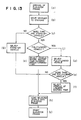
- Figs. 12 and 13 each shows a flow chart for determining the priority order of start of the vehicles.
- the elevator frame arrives (Step A).
- the vehicles are moved to the stations (Step B), and it is judged whether or not there is more than one stand-by vehicle (Step C). If there is not more than one stand-by vehicle, the vehicle is loaded into the elevator frame, and the elevator frame is started (Steps G, H and I). On the other hand, if there is more than one stand-by vehicle, the vehicle or vehicles fully loaded with passengers are selected from these stand-by vehicles (Step D).
- Steps E and F If there is more than one fully-loaded vehicle, the vehicle whose waiting time is the longest is selected (Steps E and F). The thus selected vehicle is loaded into the elevator frame, and the elevator frame is started (Steps H and I).
- the fully-loaded vehicles are selected according to the priority based on the waiting time, and therefore the transport efficiency can be enhanced at those times when the number of the passengers to be transported is large.
- Steps (a) to (c) are the same as Steps A to C of Fig. 12, respectively. If there is more than one stand-by vehicle, it is judged whether or not the stand-by vehicles are fully loaded with passengers (Step (j)). If there is no fully-loaded vehicle, the vehicle whose waiting time exceeds a predetermined period of time is selected (Step (k)). If there is at least one fully-loaded vehicle, such vehicle is selected (Step (d)). If there is more than one fully-loaded vehicle, the vehicle whose waiting time is the longest is selected (Steps (e) and (f)). The selected vehicle is loaded into the elevator frame, and the elevator frame is started (Steps (h) and (i)).
- this vehicle is selected and is loaded into the elevator frame, and the elevator frame is started (Steps (c), (g), (h) and (i)).
- the transport efficiency can be enhanced at those times when the number of the passengers to be transported is not so large.
- the above embodiments are intended merely to improve the capability of transporting passengers between the vertically-spaced two places.
- the operation of the passenger transport installation may be needed to be related to the operation of other transportation facilities, such as a subway schedule as shown in Fig. 1. Therefore, the operation of a passenger transport installation will now be described with reference to Figs. 14 and 15, in which it takes less time for passengers to wait for a subway train running according to the schedule, and the transport can be carried out efficiently.
- the passenger transport installation of Fig. 14 is similar to the passenger transport installation of Fig. 1 in that a building 3 on the ground 1 and an underground space 2 are interconnected by an elevator passage 6, that an elevator frame (holder) 15 is mounted within the elevator passage 6 for vertical movement therealong, that a rope is connected to the elevator frame 15 and is extended around a rope wheel 13 which is driven by a motor 12, that vehicles 17 are adapted to be loaded into the elevator frame 15, that there is provided a station 8 where the vehicles 17 are unloaded from the elevator frame 15 to allow passengers to get on and off the vehicle, the station 8 communicating with the elevator passage 6, and that the underground space 2 communicates with a subway platform 5 for a subway train 4.
- the subway train 4 is run or operated on schedule according to instructions give by an operation control device 71 provided within an operation instruction room 70.
- the operation instructions are fed from the operation control device 71 to the train 4 via signal lines 72A and 72B and a signal receiver device 4C.
- the operation control device 71 is connected via a data communication line 74 to a controller 73 for controlling the operation (upward and downward movement) of the elevator frame 15, so that train operation information, such as train arrival information and train destination information, is transmitted to the controller 73.
- the controller 73 operates the elevator frame 15 in accordance with the train operation information, so that the elevator frame 15 is moved in connection with the operation of the train 4.
- Step I the passenger transport installation is activated, that is, put into an operative condition
- Step II the.controller 73 receives the subway train operation information from the operation control device 71 within the operation instruction room 70 (Step II). It is judged whether or not the time when this train operation information is received by the controller 73 is a predetermined period of time before the train arrives (Step III). If this time is not the predetermined time before the train arrival, the ordinary services are continued.
- Step IV a required number of the elevator frames for transporting passengers (who are to transfer to the train) is calculated.
- the calculated number of the elevator frames are selected (Step V), and the elevator frames are once stopped at the reference stations (Step VI).
- an indication of a transfer-to-train operation is made within the vehicles within the thus stopped elevator frames and is also given to the reference stations (Step VII), thus giving information service telling the departure time of the transfer train, its destination, the line of the subway platform where the train arrives, and so on.
- the calling from other stations to the elevator frame stopped at the reference station is not accepted, and if such calling is already accepted, such acceptance is canceled and is assigned to other elevator frame or frames.
- Step IX it is judged whether or not a predetermined period of time is passed after the train arrives (Step IX). If the predetermined period of time is passed, the elevator frame is started to move toward the connection floor (Step X). Even if the predetermined period of time is not passed, it is judged whether or not the vehicle is fully loaded with passengers (Step XI). If this judgment is YES, the elevator frame is started to move toward the connection floor (Step X).
- Step IX the elevator frame remains stand-by until the predetermined period of time is passed. After the passengers get off the vehicle upon arrival of the elevator frame at the connection floor, the operation of the passenger transport installation is sepa rated from the operation of the subway train, and the ordinary services are resumed (Step XII).
- the operations of all the elevator frames may be related to the train operation.
- the number of the elevator passages as well as the number of the elevator frames is large, the number of the elevator passages to be used as well as the number of the elevator frames to be operated may be determined in accordance with the schedule of the subway. Also, the number of the elevator passages may be increased to provide a separate passenger transport installation which is exclusively operated in accordance with the schedule of the subway.
- the elevator frames moving along the elevator passages are suspended by the rope, and this rope is extended around the rope wheels and is driven.
- the elevator frame may be moved upward and downward by winding and unwinding the rope relative to a drum.
- the elevator frame is reciprocally moved upward and downward. If it is desired to further increase the transport capability, this can be done by making the vehicle large-sized and by increasing the speed of upward and downward movement of the elevator frame.
- such procedures are expensive at present, and therefore are not practical. For this reason, it is desirable to provide a transport installation of Figs. 16 to 19 which can continuously move vehicles.
- FIG. 16 to 19 There are provided two elevator passages 46 and 47 which are spaced from each other and extend between a building 3 on the ground and an underground space 2.
- the upper ends of the two elevator passages 46 and 47 are interconnected by an upper horizontal passage 48, and the lower ends thereof are interconnected by a lower horizontal passage 49, thereby forming a square-shaped continuous passage as a whole.
- a pair of sprockets 50 are provided at each of the four corners of this square-shaped passage.
- a pair of endless chains 51 are extended respectively around the sprockets 50 at each of the four corners. At least one pair of sprockets 50 at one of the four corners are connected to a motor (not shown) so as to be driven.
- a plurality of support members 52 are rotatably connected between the pair of chains 51 extending around the sprockets 51.
- the support members 52 are support or holder members corresponding to the elevator frames 15, 31, 32, 35A, 35B and 39 of the above-mentioned embodiments.
- the support member 52 is in the form of a rod or shaft.
- a grip mechanism 54 for releaseably gripping the support member 52 is mounted on each of vehicles 53. By releaseably engaging the grip mechanism 54 with the support member 52, the vehicle 53 can be moved upward and downward along the elevator passages 46 and 47 and also can be moved horizontally along the upper and lower horizontal passages 48 and 49.
- each of the top and bottom stations 7 and 8 comprises travel passages 9 along which the vehicles 53 moves, and platforms 10 where passengers get on and off the vehicles.
- the vehicle 53 has a suspension frame 57 connectable to the grip mechanism 54, and has entrance/exit openings 58A and 58B opening transverse to the direction of travel of the vehicle.
- the vehicle 53 also has wheels 59 by which the vehicle is moved on the travel passages 9.
- the wheels 59 are driven by a motor 60 for self-propelling purposes.
- this vehicle 53 within the upper horizontal passage 48 moves toward the lowering-purpose elevator passage 46 at a speed substantially equal to the speed of the chains 51, and at the same time the grip mechanism 54 grips the support member 52 on the chains 51.
- the vehicle 53 is guided toward the elevator passage 46 and is lowered therealong.
- the vehicle 53 is guided into the lower horizontal passage 49 at the lower end of the elevator passage 46, and at the synchronizing area L1 of the lower horizontal passage 49, the grip mechanism 54 is disengaged from the support member 52, and the vehicle is self-propelled toward the lower inlet/outlet opening 56A.
- the vehicle 53 is moved into the bottom station 8 through the lower inlet/outlet opening 56A, and moves along the travel passage 9, and stops at the vacant platform 10 to allow the passengers to get off the vehicle.
- the vehicle 53 carrying the passengers is guided into the lower horizontal passage 49 through the lower inlet/outlet opening 56B, and the grip mechanism 54 of the vehicle 53 grips the support member at the synchronizing area L2.
- the vehicle 53 is transferred to the upper horizontal passage 48 through the hoisting-purpose elevator passage 47, and then is moved into the top station 7 through the upper inlet/outlet opening 55B.
- the vehicles 53 are successively operated in the above manner, and many vehicles are continuously moved vertically within the elevator passages 46 and 47, thus shortening the waiting time.
- elevator frames may be connected to the chains 51 such that the vehicles are loaded into and unload from the respective elevator frames at the synchronizing areas L1 and L2.
- the vehicles are driven for movement along the travel passages by either the drive device mounted on the vehicle or the drive device mounted on the floor.
- travel passages 9F at the top station 7 and the lower station 8 disposed parallel to the upper and lower horizontal passages extending between the two elevator passages 46 and 47 may have a gradient, as shown in Fig. 20. More specifically, the travel passage 9F of the top station 7 has a falling gradient from the lower inlet/outlet opening 55B toward the lower inlet/outlet opening 55A, and the travel passage 9F of the bottom station 8 has a rising gradient from the upper inlet/outlet opening 56A toward the lower inlet/outlet opening 56B.
- the vehicle 53 can be moved by itself. In this case, the speed of the vehicle need be regulated by either an external brake device or a brake device mounted on the vehicle. This arrangement obviates the need for the drive device for driving the vehicle 53.
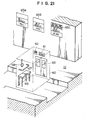
- Fig. 21 shows one example of an indication device provided at the vehicle and the stations. While passengers getting on a vehicle 60 wait for departure, they often feel somewhat irritated before the vehicle starts moving toward the elevator passage. It is necessary to relieve such irritation, and one means for achieving this is anyway to move the vehicle 60 toward the elevator passage at a low speed.
- a departure time indication device 61 (which, for example, indicates the departure time in a count-down manner) and a voice indicator 62 may be provided within the vehicle 60, and besides the vehicle may be provided with windows 63 through which the passengers within the vehicle can view a multi-vision device 64 (Fig. 16). These serve to relieve the irritation of the passengers.
- These serve to relieve the irritation of the passengers.
- information panels 65A to 65C respectively representing the departure waiting times and other conditions of the respective vehicles, are mounted on the nearly wall. With this arrangement, the passengers can select suitable vehicle.
- hand straps, chairs, handrails, etc. may be provided within the vehicle 60 so as to improve the safety of the passengers.
Abstract
Description
- This invention relates to a passenger transport installation (facilities) suited for transporting a large number of people between vertically-spaced two places, a vehicle for use in such transport installation, and a method of operating such transport installation.
- Japanese Patent Unexamined Publication Nos. 59-153773 and 61-188384 disclose typical examples of transport installations for mass-transporting people between vertically-spaced two places, in which an elevator device is used, and the interior of the cage or cab is vertically divided into upper and lower cage rooms. Japanese Patent Unexamined Publication No. 58-220068 discloses another type of transport installation in which a self-propelled cage carrying people is moved from one elevator passage to another and then is moved vertically.
- In the above elevator device, the passengers get on and off the cage while the cage is stopped in the elevator passage, and therefore the flow of the passengers is not continuous. Particularly where the cage is for mass-transportation purposes and hence has a large passenger capacity, it takes more time for the passengers to get on and off the cage than for the cage to move up or down to a destination place. In this case, even if the speed of movement of the cage is increased, a period of time elapsed from a point of time when passengers get on the cage and to a point of time when they get off the cage at the destination place can not be reduced so much, and the platform from which people get on and off the cage is always crowded.
- Thus, although the above-mentioned conventional techniques are suited for transporting a large number of passengers at a time at high speed, a continuous transportation has not been taken into consideration. Therefore, the ability to transport passengers within a predetermined period of time, that is, the transport capability, has been limited.
- It is therefore an object of this invention to provide a passenger transport installation in which a large number of people can be efficiently transported between vertically-spaced two places.
- Another object of the invention is to provide a passenger transport installation and a method of operating such installation, in which even when passengers are getting on and off a vehicle, another vehicle can be moved upward or downward.
- A further object of the invention is to provide a passenger transport installation of which transport capability can be improved without increasing the number of elevator passages along which vehicles move upward or downward.
- In one aspect of the present invention, stations to which vehicles are conducted from an elevator passage and where the vehicles stop to enable passengers to get on and off the vehicles are provided to communicate with the elevator passage.
- The vehicles can be moved upward and downward along the elevator passage by means of holder means, and can be disengaged from the holder means so as to move toward the stations.
- The vehicles can be moved upward and downward along the elevator passage while passengers get on and off other vehicles at the stations.
- Since the passengers can get on and off the vehicles stopped at the stations spaced from the elevator passage, the elevator passage is not blocked when the passenger get on and off the vehicles. Therefore, while the passengers get on and off the vehicles at the stations, other vehicles can be moved along the elevator passage. Thus, the elevator passage can be exclusively used for upward and downward movement of vehicles, thereby enhancing a transport capability.
-
- Fig. 1 is a partly-broken, perspective view of a passenger transport installation according to the present invention;
- Fig. 2 is a vertical cross-sectional view of the transport installation of Fig. 1 in the vicinity of an elevator passage;
- Fig. 3 is an enlarged cross-sectional view taken along the line III-III of Fig. 2;
- Fig. 4 is a front-elevational view showing a holder and a vehicle, used in the installation of Fig. 1;
- Fig. 5 is a vertical cross-sectional view of a modified elevator passage used in the transport installation of the invention;
- Fig. 6 is a perspective view of a station of the installation of Fig. 5;
- Figs. 7 and 8 are horizontal cross-sectional views of modified forms of the invention, respectively, showing the relation between an elevator passage and a station;
- Figs. 9 to 11 are side-elevational views of vehicles incorporating respective drive devices of different kinds used in the present inventions;
- Fig. 12 is a flow chart for operating the passenger transport installation;
- Fig. 13 is a flow chart similar to Fig. 12 but showing a modified operation;
- Fig. 14 is a partly-broken view of a further modified passenger transport installation of the present invention;
- Fig. 15 is a flow chart for operating the installation of Fig. 14;
- Fig. 16 is a partly-broken, perspective view of a further modified passenger transport installation of the present invention;
- Fig. 17 is an enlarged perspective view of a vehicle used in the installation of Fig. 16;
- Fig. 18 is an enlarged horizontal cross-sectional view, showing a bottom station of the installation of Fig. 16;
- Fig. 19 is an enlarged side-elevational view, showing a vehicle in a lower horizontal passage of the installation of Fig. 16;
- Fig. 20 is a vertical cross-sectional view, showing modified upper and lower horizontal passages used in the installation of Fig. 16; and
- Fig. 21 is a schematic perspective view, showing the relation between a vehicle and a station according to the invention.
- A first embodiment of the invention will now be described with reference to Figs. 1 to 4. This embodiment is directed to a passenger transport instal lation for transporting passengers between the
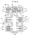
ground 1 and anunderground space 2 which are spaced vertically from each other. More specifically, there is provided anelevator passage 6 vertically extending between one or all of floors of abuilding 3 on theground 1 and an underground place which is here asubway platform 5 where people get on and off a subway train 4. Two-stage (upper and lower) top stations 7 (7A to 7D) where people get on and off vehicles are provided at and communicated with the upper end portion of theelevator passage 6. Similarly, two-stage (upper and lower) bottom stations 8 (8A to 8D) are provided at and horizontally communicated with the lower end portion of theelevator passage 6. Each of the top andbottom stations travel passage 9 along whichvehicles 17A to 17D can move, andplatforms 10 disposed at substantially the same level as the floor of thevehicles 17A to 17D when thevehicles 17A to 17D are disposed at that station (see Fig. 3). Thetravel passage 9 communicates with theplatform 10 through an inlet/outlet opening 11. The inlet/outlet opening 11 may either be merely kept open or be closable by an associated shutter such as a door. Provided above the upper end of theelevator passage 6 is a machine room where amotor 12 as well as juxtaposedrope wheels 13 is provided. Therope wheels 13 are driven for rotation either directly by themotor 13 or indirectly thereby through a speed reducer. Arope 14 is extended around therope wheels 13 in such a manner that the opposite ends of therope 14 are suspended in theelevator passage 6. Elevator frames (holders) 15 (15A and 15B) are connected to the opposite ends of therope 14, respectively. Each of theelevator frames floors lower floors top stations bottom stations Guide rails 6G are mounted in and extend along theelevator passage 6, and each of theelevator frames guide rails 6G for movement therealong. Although not shown in the drawings, each of thefloors vehicles 17A to 17D are guided onto the floors in a horizontal direction. This guide means may be a passage identical in configuration to thetravel passage 9 of thestation vehicles 17A to 17D are movable by means of wheels, and each vehicle also includes astopper 18 extending downwardly from its floor. Thestopper 18 is engageable withpositioning stoppers 19 provided at predetermined positions in thetravel passage 9 for thestations 7A to 7D, and is also engageable with connectingstoppers 20 provided at thefloors elevator frames - In the above construction, for example, when going from the
ground 1 to theunderground space 2, passengers go to either the upper orlower platform 10 of thetop stations 7A to 7D, and pass through the opening 11 to get on thevacant vehicles 17A. Immediately when the number limit is reached or when it comes time to start, the door is closed even if the number limit has not yet been reached. Simultaneously with the getting-on and off at thetop station 7, passengers get on and off thevehicles 17A at thebottom station 8. At this time, that is, during the time when the passengers get on and off the vehicles at thestations elevator frames respective vehicles 17B carrying passengers, are moving upward and downward, or thevehicles 17B are moving from theelevator frame 15A, stopped at the floor, toward thetop station 7B as indicated by arrow a in Fig. 2 (Similarly, at this time, thevehicles 17B are moving from theelevator frame 15B toward thebottom station 8B). - After the
vehicles 17B reach thestations respective elevator frames stopper 18 of each of the stand-byvehicles 17A holding the passengers is disengaged from thepositioning stopper 19 at thetravel passage 9, so that thevehicles 17A become themoving vehicles 17D to be moved into theelevator frame elevator frame 15A. Then, thestopper 18 of eachvehicle 17D is engaged with the connectingstopper 20 mounted on thefloor 16B of theelevator frame vehicles 17D are ready to move upward and downward, respectively, and are now indicated byreference numeral 17B. When thevehicles 17B are completely loaded respectively into the elevator frames 15A and 15B disposed respectively at the upper and lower ends of theelevator passage 6, themotor 12 is driven to move the twoelevator frames - The movements of the elevator frames 15A and 15B as well as the movements of the
vehicles 17A to 17D are repeated in the above-mentioned manner, thereby transporting the passengers. - Passengers can smoothly get on and off each
vehicle 17A by the provision of theplatforms 10 on the opposite sides of thetravel passage 9, as shown in Fig. 3. In this case, those passengers getting off are led out of thevehicle 17A in a direction of arrow c, and after those passengers get off, the waiting passengers are led into thevehicle 17A in a direction of arrow d, thereby avoiding the crowdedness at the station. - In this embodiment, the places where the passengers get on and off the
vehicles 17A are spaced away from theelevator passage 6, the elevator frames 15A and 15B carrying other vehicles can be moved upward and downward in theelevator passage 6 even when passengers get on and off thevehicles 17A. Therefore, the vehicles can always be moved along theelevator passage 6, thereby increasing the transport capability. - In the above embodiment, although the two-stage elevator frames 15A and 15B are connected respectively to the opposite ends of the
rope 14 and are suspended in thesingle elevator passage 6, there may be provided two juxtaposedelevator passages 6 such that the elevator frames 15A and 15B are caused to move upward and downward in the two elevator passages, respectively, independently of each other. Theelevator frame - In Fig. 2,
reference numeral 6B denotes a shock absorber mounted at the bottom of theelevator passage 6. - In the above embodiment, the
vehicles 17B are loaded respectively into the upper and lower stages of the elevator frames 15A and 15B. However, there are some time zones or periods when the number of passengers is not so large. At these time zones, the transportation can be done by loading only onevehicle 17B into one of the two stages of each of the elevator frames 15A and 15B. In this case, as shown in Fig. 2, thevehicle 17B is moved from the lower stage of theelevator frame 15A into thelower top station 7B, and at the same time thevehicle 17D is loaded from the uppertop station 7C into the upper stage of theelevator frame 15A, thereby further shortening the operation time. - Although the above embodiment is directed to the transport installation for transporting passengers between the
ground 1 and theunderground space 2, the invention can, of course, be used for transporting the passengers between theground 1 and the uppermost floor of thebuilding 3. - In the above embodiment, the vertical elevating distance is long, and there is no elevator-stop floor intermediate the
ground 1 and theunderground space 2. In this case, if there occurs an accident or an emergency during the upward and downward movements of the elevator frames 15A and 15B along theelevator passage 6, it may be impossible to move the elevator frames 15A and 15B to the top andbottom stations elevator passage 6, the number of theshelter yards 21 corresponding to the number of the stages of the elevator frames 15A and 15B, respectively. Where eachshelter yard 21 has an increased depth, it can be used for storing aspare vehicle 17A or for temporarily storing the vehicle. Further,work spaces 22 can be provided back from to communicate with theshelter yards 21C and 21D used for vehicle storage purposes, as shown in Fig. 2, in which case simple checking or repair of thevehicles 17A can be made without stopping the operation of thevehicles 17B. Further,shelter passages 23, for example, communicating with the shelter yards 21A and 21B can be provided, in which instance in the case of an emergency, passengers on thevehicles 17A taking shelter in the shelter yard 21A and 21B can be guided into a safe place via theshelter passages 23. - A modified passenger transport installation will now be described with reference to Figs. 5 and 6. In this embodiment, a pair of
vertical elevator passages elevator passages top station 26, and the lower ends thereof are communicated with each other by abottom station 27. The midway portions of theelevator passages communication passage 28. Thetop station 26 hasend stations 26E and anintermediate station 26M, and similarly thebottom station 27 hasend stations 27E and anintermediate station 27M. Each of theintermediate stations outlet passages passages 30A to 30C extending between the inlet/outlet passages communication passage 28 may be of the same construction as that of theintermediate stations stations travel passage 9 along which the vehicles move, andplatforms 10, as shown in Fig. 3. If it is necessary for passengers to get on and off the vehicle at thecommunication passage 28, thecommunication passage 28 may haveplatforms 10 as shown in Fig. 3. In the above construction, elevator frames 31 and 32 move upward and downward along theelevator passages elevator passages vehicles 33 with respect to the elevator frames 31 and 32 is carried out in a manner similar to that described above with reference to Fig. 2. More specifically, while passengers get on and off thevehicles 33 at the top andbottom stations other vehicles 33 carrying passengers move along theelevator passages - As described above in Fig. 6, the
intermediate stations elevator passages passages vehicle 33, moving upward along theelevator passage 24, can be moved into theintermediate station 26M to be guided into thepassage 30A as indicated by arrow e, allowing passengers to get on and off thisvehicle 33. At this time, if there is noother vehicle 33 in thepassage 30A and if theelevator frame 32 is on stand-by at theopposite elevator passage 25, theabove vehicle 33 guided into thepassage 30A can be loaded into theelevator frame 32 via the inlet/outlet passage 29B, as indicated by arrow f, so that this vehicle can be moved downward. Also, when thevehicles 33 move upward along therespective elevator passages intermediate station 26M, one of thevehicle 33 can be guided into thepassage 30A as indicated by arrows e and f, whereas theother vehicle 33 can be guided into thepassage 30C as indicated by arrows g and h. Thus,many vehicles 33 can be operated smoothly. Further, when thepassages other vehicles 33 enter the inlet/outlet passages vehicles 33 can be guided, for example, into thevacant passage 30B, in the directions as indicated by arrows i and j, allowing passengers to get on and off thesevehicles 33. Then, thevehicles 33 are moved in the directions as indicated by arrows k and l to return respectively to the inlet/outlet passages vehicles 33. - Figs. 7 and 8 show the arrangement of a station with respect to an elevator passage. Fig. 7 shows a construction in which two
elevator frames elevator passage 34. Three vehicle stand-by places 3A to 36C are provided respectively in facing relation to three sides of the elevator frame 35 in a stopped position, and similarly three vehicle stand-byplaces 36D to 36F are provided respectively in facing relation to three sides of theelevator frame 35B in a stopped position.Platforms 37 are provided adjacent to the stand-byplaces 36A to 36F, respectively. With this arrangement, the unloading of thevehicles 38 from the elevator frames 35A and 35B is carried out at the same time when the loading ofother vehicles 38 into the elevator frames 35A and 35B is carried out. Also, passengers get on the vehicle at the same time when other passengers get off other vehicle. The movements of thevehicles 38 on a horizontal plane are carried out as indicated by arrows in Fig. 7, and therefore the schedule of the operation can be determined in a less limited manner. This construction may be so modified that only one elevator frame can be moved along theelevator passage 34, in which case four stand-by places may be provided on all of the four sides of the elevator frame in a stopped position. Referring to Fig. 8, asingle elevator frame 39 is adapted to move along asingle elevator passage 34, andvehicle travel passages elevator passage 34, respectively. Theelevator frame 39 has a horizontal size capable of holding twovehicles 38, and each of thetravel passages vehicle 38 is movable. When theelevator frame 39 is stopped at a position opposed to thetravel passages vehicles 38 are moved in a direction as indicated by arrows, so that thevehicles 38 within theelevator frame 39 are moved into thetravel passages other vehicles 38 having been in thetravel passages elevator frame 39. During the upward or downward movement of theelevator frame 39, passengers can get on and off thevehicles 38 disposed at thetravel passages - Figs. 9 to 11 respectively show drive devices for driving a
vehicle 38 for horizontal movement. More specifically, in Fig. 9, thevehicle 38 is driven by a linear motor. Areaction plate 42B is laid on each of a travel floor 41 (on which thevehicle 38 moves) and the floor of the elevator frame. Amagnetic pole 42A is provided on the lower surface of the floor of thevehicle 38 disposed in opposed relation to thereaction plate 42B. In Fig. 10, for example, achain 44 moving in the direction of movement of thevehicle 38 is provided on thetravel floor 41 on which thevehicle 38 moves. Achain engaging device 43 is mounted on thevehicle 38. Thevehicle 38 is moved and stopped by causing thechain engaging device 43 to engage and disengage thechain 44. In Fig. 11, adrive motor 45 is mounted on avehicle 38, and thedrive motor 45 drives the wheels of the vehicle to thereby move the vehicle. These drive devices are shown merely by way of example, and any other suitable known drive device or moving device can be used. - Next, one example of the operation of the vehicles will now be described with reference to Figs. 12 and 13. Figs. 12 and 13 each shows a flow chart for determining the priority order of start of the vehicles. Referring to Fig. 12, the elevator frame arrives (Step A). The vehicles are moved to the stations (Step B), and it is judged whether or not there is more than one stand-by vehicle (Step C). If there is not more than one stand-by vehicle, the vehicle is loaded into the elevator frame, and the elevator frame is started (Steps G, H and I). On the other hand, if there is more than one stand-by vehicle, the vehicle or vehicles fully loaded with passengers are selected from these stand-by vehicles (Step D). If there is more than one fully-loaded vehicle, the vehicle whose waiting time is the longest is selected (Steps E and F). The thus selected vehicle is loaded into the elevator frame, and the elevator frame is started (Steps H and I). Thus, the fully-loaded vehicles are selected according to the priority based on the waiting time, and therefore the transport efficiency can be enhanced at those times when the number of the passengers to be transported is large.
- Referring to Fig. 13, Steps (a) to (c) are the same as Steps A to C of Fig. 12, respectively. If there is more than one stand-by vehicle, it is judged whether or not the stand-by vehicles are fully loaded with passengers (Step (j)). If there is no fully-loaded vehicle, the vehicle whose waiting time exceeds a predetermined period of time is selected (Step (k)). If there is at least one fully-loaded vehicle, such vehicle is selected (Step (d)). If there is more than one fully-loaded vehicle, the vehicle whose waiting time is the longest is selected (Steps (e) and (f)). The selected vehicle is loaded into the elevator frame, and the elevator frame is started (Steps (h) and (i)). If there is not more than one stand-by vehicle, this vehicle is selected and is loaded into the elevator frame, and the elevator frame is started (Steps (c), (g), (h) and (i)). Thus, the transport efficiency can be enhanced at those times when the number of the passengers to be transported is not so large.
- The above embodiments are intended merely to improve the capability of transporting passengers between the vertically-spaced two places. However, the operation of the passenger transport installation may be needed to be related to the operation of other transportation facilities, such as a subway schedule as shown in Fig. 1. Therefore, the operation of a passenger transport installation will now be described with reference to Figs. 14 and 15, in which it takes less time for passengers to wait for a subway train running according to the schedule, and the transport can be carried out efficiently.
- The passenger transport installation of Fig. 14 is similar to the passenger transport installation of Fig. 1 in that a
building 3 on theground 1 and anunderground space 2 are interconnected by anelevator passage 6, that an elevator frame (holder) 15 is mounted within theelevator passage 6 for vertical movement therealong, that a rope is connected to theelevator frame 15 and is extended around arope wheel 13 which is driven by amotor 12, thatvehicles 17 are adapted to be loaded into theelevator frame 15, that there is provided astation 8 where thevehicles 17 are unloaded from theelevator frame 15 to allow passengers to get on and off the vehicle, thestation 8 communicating with theelevator passage 6, and that theunderground space 2 communicates with asubway platform 5 for a subway train 4. The subway train 4 is run or operated on schedule according to instructions give by anoperation control device 71 provided within anoperation instruction room 70. The operation instructions are fed from theoperation control device 71 to the train 4 viasignal lines signal receiver device 4C. Theoperation control device 71 is connected via adata communication line 74 to acontroller 73 for controlling the operation (upward and downward movement) of theelevator frame 15, so that train operation information, such as train arrival information and train destination information, is transmitted to thecontroller 73. Thecontroller 73 operates theelevator frame 15 in accordance with the train operation information, so that theelevator frame 15 is moved in connection with the operation of the train 4. - The operation of the
elevator frame 15 as well as the operation of the train 4 will now be described with reference to a flow chart of Fig. 15. First, the passenger transport installation is activated, that is, put into an operative condition (Step I), and ordinary services are started. In this condition,the.controller 73 receives the subway train operation information from theoperation control device 71 within the operation instruction room 70 (Step II). It is judged whether or not the time when this train operation information is received by thecontroller 73 is a predetermined period of time before the train arrives (Step III). If this time is not the predetermined time before the train arrival, the ordinary services are continued. If this time is the predetermined time before the train arrival, a required number of the elevator frames for transporting passengers (who are to transfer to the train) is calculated (Step IV). The calculated number of the elevator frames are selected (Step V), and the elevator frames are once stopped at the reference stations (Step VI). Then, an indication of a transfer-to-train operation is made within the vehicles within the thus stopped elevator frames and is also given to the reference stations (Step VII), thus giving information service telling the departure time of the transfer train, its destination, the line of the subway platform where the train arrives, and so on. Further, the calling from other stations to the elevator frame stopped at the reference station is not accepted, and if such calling is already accepted, such acceptance is canceled and is assigned to other elevator frame or frames. And, before the arrival of the train, the elevator frame is caused to reach the station communicating with the subway platform, allowing the passengers to get off the vehicle (Step VIII), so that the vehicle is on stand-by for receiving passengers who will get off the train. Then, it is judged whether or not a predetermined period of time is passed after the train arrives (Step IX). If the predetermined period of time is passed, the elevator frame is started to move toward the connection floor (Step X). Even if the predetermined period of time is not passed, it is judged whether or not the vehicle is fully loaded with passengers (Step XI). If this judgment is YES, the elevator frame is started to move toward the connection floor (Step X). If the judgment is NO, the elevator frame remains stand-by until the predetermined period of time is passed (Step IX). After the passengers get off the vehicle upon arrival of the elevator frame at the connection floor, the operation of the passenger transport installation is sepa rated from the operation of the subway train, and the ordinary services are resumed (Step XII). - In this embodiment, passengers never fail to miss the train, and the time required for the passengers (who get off the train) to wait for the vehicles can be shortened.
- In this embodiment, in case the number of the elevator passages as well as the number of the elevator frames is small, the operations of all the elevator frames may be related to the train operation. In case the number of the elevator passages as well as the number of the elevator frames is large, the number of the elevator passages to be used as well as the number of the elevator frames to be operated may be determined in accordance with the schedule of the subway. Also, the number of the elevator passages may be increased to provide a separate passenger transport installation which is exclusively operated in accordance with the schedule of the subway.
- In the above embodiments, the elevator frames moving along the elevator passages are suspended by the rope, and this rope is extended around the rope wheels and is driven. However, the elevator frame may be moved upward and downward by winding and unwinding the rope relative to a drum. In any case, the elevator frame is reciprocally moved upward and downward. If it is desired to further increase the transport capability, this can be done by making the vehicle large-sized and by increasing the speed of upward and downward movement of the elevator frame. However, such procedures are expensive at present, and therefore are not practical. For this reason, it is desirable to provide a transport installation of Figs. 16 to 19 which can continuously move vehicles.
- Such transport installation will now be described with reference to Figs. 16 to 19. There are provided two
elevator passages building 3 on the ground and anunderground space 2. The upper ends of the twoelevator passages horizontal passage 48, and the lower ends thereof are interconnected by a lowerhorizontal passage 49, thereby forming a square-shaped continuous passage as a whole. A pair ofsprockets 50 are provided at each of the four corners of this square-shaped passage. A pair ofendless chains 51 are extended respectively around thesprockets 50 at each of the four corners. At least one pair ofsprockets 50 at one of the four corners are connected to a motor (not shown) so as to be driven. A plurality ofsupport members 52 are rotatably connected between the pair ofchains 51 extending around thesprockets 51. Thesupport members 52 are support or holder members corresponding to the elevator frames 15, 31, 32, 35A, 35B and 39 of the above-mentioned embodiments. For example, thesupport member 52 is in the form of a rod or shaft. Agrip mechanism 54 for releaseably gripping thesupport member 52 is mounted on each ofvehicles 53. By releaseably engaging thegrip mechanism 54 with thesupport member 52, thevehicle 53 can be moved upward and downward along theelevator passages horizontal passages - Upper inlet/
outlet openings horizontal passage 48, and lower inlet/outlet openings horizontal passage 49. Atop station 7 communicates with the upperhorizontal passage 48 via the upper inlet/outlet openings bottom station 8 communicates with the lowerhorizontal passage 49 via the lower inlet/outlet openings bottom stations travel passages 9 along which thevehicles 53 moves, andplatforms 10 where passengers get on and off the vehicles. - That portion L1 (Fig. 18) of the horizontal passage 48 (49) extending between the
elevator passage 46 and the inlet/outlet opening 55A (56A), as well as that portion L2 (Fig. 18) of the horizontal passage 48 (49) extending between theelevator passage 47 and the inlet/outlet opening 55B (56B), is a synchronizing area where the speed of thechains 51 is equal to the speed of movement of thevehicles 53. - The
vehicle 53 has asuspension frame 57 connectable to thegrip mechanism 54, and has entrance/exit openings vehicle 53 also haswheels 59 by which the vehicle is moved on thetravel passages 9. Thewheels 59 are driven by amotor 60 for self-propelling purposes. - Next, the operation of the transport installation of this construction will now be described. First, reference is made to the case where the
chains 51 are driven in such a manner that theelevator passage 46 is used only for downwardly moving the vehicles whereas theother elevator passage 47 is used only for upwardly moving the vehicles. In this case, for example, when going from thetop station 7 to thebottom station 8, passengers get on one of thevehicles 53 at theupper platform 10. When the number limit with respect to thisvehicle 53 is reached or upon lapse of a predetermined period of time period, thevehicle 53 is moved along thetravel passage 9 toward the upper inlet/outlet opening 55A, and is introduced into the upperhorizontal passage 48 through theopening 55A. Then, thisvehicle 53 within the upperhorizontal passage 48 moves toward the lowering-purpose elevator passage 46 at a speed substantially equal to the speed of thechains 51, and at the same time thegrip mechanism 54 grips thesupport member 52 on thechains 51. As a result of this gripping, thevehicle 53 is guided toward theelevator passage 46 and is lowered therealong. Then, thevehicle 53 is guided into the lowerhorizontal passage 49 at the lower end of theelevator passage 46, and at the synchronizing area L1 of the lowerhorizontal passage 49, thegrip mechanism 54 is disengaged from thesupport member 52, and the vehicle is self-propelled toward the lower inlet/outlet opening 56A. Then, thevehicle 53 is moved into thebottom station 8 through the lower inlet/outlet opening 56A, and moves along thetravel passage 9, and stops at thevacant platform 10 to allow the passengers to get off the vehicle. When passengers are to be transported from thebottom station 8 to thetop station 7, thevehicle 53 carrying the passengers is guided into the lowerhorizontal passage 49 through the lower inlet/outlet opening 56B, and thegrip mechanism 54 of thevehicle 53 grips the support member at the synchronizing area L2. Then, thevehicle 53 is transferred to the upperhorizontal passage 48 through the hoisting-purpose elevator passage 47, and then is moved into thetop station 7 through the upper inlet/outlet opening 55B. - The
vehicles 53 are successively operated in the above manner, and many vehicles are continuously moved vertically within theelevator passages - In this embodiment, although the
vehicle 53 is designed to be suspended directly from thesupport member 52 connected to thechains 51, elevator frames may be connected to thechains 51 such that the vehicles are loaded into and unload from the respective elevator frames at the synchronizing areas L1 and L2. - In the above embodiment, the vehicles are driven for movement along the travel passages by either the drive device mounted on the vehicle or the drive device mounted on the floor. Alternatively,
travel passages 9F at thetop station 7 and thelower station 8 disposed parallel to the upper and lower horizontal passages extending between the twoelevator passages travel passage 9F of thetop station 7 has a falling gradient from the lower inlet/outlet opening 55B toward the lower inlet/outlet opening 55A, and thetravel passage 9F of thebottom station 8 has a rising gradient from the upper inlet/outlet opening 56A toward the lower inlet/outlet opening 56B. With this arrangement, thevehicle 53 can be moved by itself. In this case, the speed of the vehicle need be regulated by either an external brake device or a brake device mounted on the vehicle. This arrangement obviates the need for the drive device for driving thevehicle 53. - Fig. 21 shows one example of an indication device provided at the vehicle and the stations. While passengers getting on a
vehicle 60 wait for departure, they often feel somewhat irritated before the vehicle starts moving toward the elevator passage. It is necessary to relieve such irritation, and one means for achieving this is anyway to move thevehicle 60 toward the elevator passage at a low speed. In addition, a departure time indication device 61 (which, for example, indicates the departure time in a count-down manner) and avoice indicator 62 may be provided within thevehicle 60, and besides the vehicle may be provided withwindows 63 through which the passengers within the vehicle can view a multi-vision device 64 (Fig. 16). These serve to relieve the irritation of the passengers. These are services to the passengers within thevehicle 60. For passengers on theplatform 10,information panels 65A to 65C, respectively representing the departure waiting times and other conditions of the respective vehicles, are mounted on the nearly wall. With this arrangement, the passengers can select suitable vehicle. - Further, hand straps, chairs, handrails, etc., may be provided within the
vehicle 60 so as to improve the safety of the passengers.
Claims (26)
Applications Claiming Priority (2)
| Application Number | Priority Date | Filing Date | Title |
|---|---|---|---|
| JP66209/89 | 1989-03-20 | ||
| JP6620989 | 1989-03-20 |
Publications (3)
| Publication Number | Publication Date |
|---|---|
| EP0388814A2 true EP0388814A2 (en) | 1990-09-26 |
| EP0388814A3 EP0388814A3 (en) | 1992-06-10 |
| EP0388814B1 EP0388814B1 (en) | 1995-08-09 |
Family
ID=13309211
Family Applications (1)
| Application Number | Title | Priority Date | Filing Date |
|---|---|---|---|
| EP90105013A Expired - Lifetime EP0388814B1 (en) | 1989-03-20 | 1990-03-16 | Passenger transport installation |
Country Status (3)
| Country | Link |
|---|---|
| US (1) | US5090515A (en) |
| EP (1) | EP0388814B1 (en) |
| DE (1) | DE69021417T2 (en) |
Cited By (12)
| Publication number | Priority date | Publication date | Assignee | Title |
|---|---|---|---|---|
| EP0556595A1 (en) * | 1992-02-17 | 1993-08-25 | Inventio Ag | Passenger transport system |
| EP0595122A1 (en) * | 1992-10-27 | 1994-05-04 | Inventio Ag | Friction wheel drive for a passenger transporting device |
| EP0615946A1 (en) * | 1993-03-18 | 1994-09-21 | Inventio Ag | Vertical/horizontal passenger conveyor system |
| EP0776856A2 (en) * | 1995-11-29 | 1997-06-04 | Otis Elevator Company | Emergency elevator cab commandeering shuttle |
| EP0776852A1 (en) * | 1995-11-29 | 1997-06-04 | Otis Elevator Company | Elevator shuttle employing horizontally transferred cab |
| EP0785160A1 (en) * | 1996-01-18 | 1997-07-23 | Otis Elevator Company | Extra deck elevator shuttle |
| EP0776850A3 (en) * | 1995-11-29 | 1998-01-14 | Otis Elevator Company | Elevator cabs transferred horizontally between double deck elevators |
| EP0776851A3 (en) * | 1995-11-29 | 1998-04-15 | Otis Elevator Company | Synchronized off-shaft loading of elevator cabs |
| EP0842888A1 (en) * | 1996-11-14 | 1998-05-20 | Otis Elevator Company | Horizontal and vertical passenger transport |
| EP0781724A3 (en) * | 1995-11-29 | 1998-06-03 | Otis Elevator Company | Synchronous elevator shuttle system |
| CN105253743A (en) * | 2015-10-29 | 2016-01-20 | 浙江西子重工机械有限公司 | Elevator capable of running in parallel |
| CN115288499A (en) * | 2022-08-08 | 2022-11-04 | 中铁二院工程集团有限责任公司 | Station structure of rapid transit system |
Families Citing this family (27)
| Publication number | Priority date | Publication date | Assignee | Title |
|---|---|---|---|---|
| JPH04365771A (en) * | 1991-06-13 | 1992-12-17 | Toshiba Corp | Elevator |
| US5865274A (en) * | 1995-10-24 | 1999-02-02 | Kabushiki Kaisha Toshiba | Elevator group management control apparatus and elevator group management control method |
| US5829553A (en) * | 1995-11-29 | 1998-11-03 | Otis Elevator Company | Fail-safe movement of elevator cabs between car frames and landings |
| US5657835A (en) * | 1995-11-29 | 1997-08-19 | Otis Elevator Company | Elevator shuttle employing horizontally transferred cab |
| US5695024A (en) * | 1995-11-29 | 1997-12-09 | Otis Elevator Company | Car operated safety gate for horizontally transferrable elevator cab |
| US5785153A (en) * | 1995-11-29 | 1998-07-28 | Otis Elevator Company | Synchronizing elevator arrival at a level of a building |
| US5823299A (en) * | 1996-06-19 | 1998-10-20 | Otis Elevator Company | Shuttle elevators feeding local elevators |
| US5773772A (en) * | 1996-06-19 | 1998-06-30 | Otis Elevator Company | Transferring elevator cabs between non-contiguous hoistways |
| US5752585A (en) * | 1996-07-25 | 1998-05-19 | Otis Elevator Company | Elevator shuttle with auxiliary elevators at terminals |
| US5799755A (en) * | 1996-11-14 | 1998-09-01 | Otis Elevator Company | Linear motor transfer of cab horizontally between elevator and bogey platforms |
| SG102714A1 (en) * | 2002-05-27 | 2004-03-26 | Inventio Ag | Elevator installation with several self-propelled cars and at least three elevator hoistways situated adjacently |
| US7198136B2 (en) * | 2003-09-11 | 2007-04-03 | Otis Elevator Company | Elevator device for a multi-sky-lobby system |
| WO2006085862A1 (en) * | 2005-02-04 | 2006-08-17 | Otis Elevator Company | Announcements indicating one car is waiting for another car in the same hoistway |
| US7296660B1 (en) | 2006-05-17 | 2007-11-20 | Harry G. Bauge | Residential elevator |
| US7641024B2 (en) * | 2006-05-17 | 2010-01-05 | Bauge Harry G | Operating residential elevator |
| US7913818B2 (en) * | 2006-12-22 | 2011-03-29 | Inventio Ag | Elevator installation in a building with at least one transfer floor |
| US7882934B2 (en) * | 2006-12-22 | 2011-02-08 | Inventio Ag | Elevator installation in a building with at least one transfer floor |
| SG185101A1 (en) * | 2010-04-30 | 2012-12-28 | David Alba | System for the transfer, storage and distribution of intermodal containers |
| CN102556805B (en) * | 2011-11-09 | 2014-09-17 | 日立电梯(中国)有限公司 | Elevator device capable of improving use efficiency of shaft way |
| DE102015102564A1 (en) * | 2015-02-23 | 2016-08-25 | Thyssenkrupp Ag | Elevator system with several shafts and several cabins and additional cabin receiving shaft |
| US10017354B2 (en) | 2015-07-10 | 2018-07-10 | Otis Elevator Company | Control system for multicar elevator system |
| WO2017023962A1 (en) | 2015-08-03 | 2017-02-09 | Otis Elevator Company | Intermediate transfer station |
| WO2017027495A1 (en) * | 2015-08-11 | 2017-02-16 | Otis Elevator Company | Configurable multicar elevator system |
| US20180222722A1 (en) * | 2015-08-12 | 2018-08-09 | Otis Elevator Company | Transport system for ropeless elevator hoistway and method |
| US9598265B1 (en) * | 2015-09-28 | 2017-03-21 | Smart Lifts, Llc | Vertically and horizontally mobile elevator cabins |
| JP2020518535A (en) * | 2017-05-04 | 2020-06-25 | デイレル、イヴァン | Cross References to Autonomous Mobile Lift Related Applications N/A Federally Funded Research N/A Sequence Lists or Programs N/A |
| DE102017219744A1 (en) * | 2017-11-07 | 2019-05-09 | Thyssenkrupp Ag | Passenger conveying device with monitoring device |
Citations (6)
| Publication number | Priority date | Publication date | Assignee | Title |
|---|---|---|---|---|
| US3317005A (en) * | 1965-04-21 | 1967-05-02 | Arthur H Kehoe | Elevator system |
| US3658155A (en) * | 1970-09-15 | 1972-04-25 | William G Salter | Elevator system |
| DE2154923A1 (en) * | 1971-11-04 | 1973-05-10 | Adolf H Borst | PERSONAL LIFT |
| US4004654A (en) * | 1971-07-07 | 1977-01-25 | Trebron Holdings Limited | Elevator structure supporting apparatus |
| DE2618237A1 (en) * | 1976-04-26 | 1977-11-10 | Inventio Ag | Horizontal and vertical goods conveyor - has lift cages with transport trucks transferring goods to floor conveyors |
| US4071135A (en) * | 1975-04-28 | 1978-01-31 | Mitsubishi Denki Kabushiki Kaisha | Passenger transportation apparatus |
Family Cites Families (8)
| Publication number | Priority date | Publication date | Assignee | Title |
|---|---|---|---|---|
| US3750849A (en) * | 1970-04-21 | 1973-08-07 | Westinghouse Electric Corp | Duplex counterweightless shuttle elevator system |
| JPS51131046A (en) * | 1975-05-12 | 1976-11-15 | Hitachi Ltd | Elevator arrival order indicating device |
| JPS53119549A (en) * | 1977-03-26 | 1978-10-19 | Hitachi Ltd | Waiting time indicator for elevator cage |
| JPS5431143A (en) * | 1977-08-12 | 1979-03-07 | Hitachi Ltd | Buffer stop for elevator |
| JPS61188384A (en) * | 1985-02-12 | 1986-08-22 | 三菱電機株式会社 | Cage chamber for double deck elevator |
| JPS6298684U (en) * | 1985-12-11 | 1987-06-23 | ||
| JP2502077B2 (en) * | 1987-02-28 | 1996-05-29 | 株式会社日立製作所 | Elevator guide device |
| US4897012A (en) * | 1987-11-06 | 1990-01-30 | Custom Technologies, Inc. | Cargo handling system |
-
1990
- 1990-03-16 EP EP90105013A patent/EP0388814B1/en not_active Expired - Lifetime
- 1990-03-16 DE DE69021417T patent/DE69021417T2/en not_active Expired - Fee Related
- 1990-03-19 US US07/495,084 patent/US5090515A/en not_active Expired - Fee Related
Patent Citations (6)
| Publication number | Priority date | Publication date | Assignee | Title |
|---|---|---|---|---|
| US3317005A (en) * | 1965-04-21 | 1967-05-02 | Arthur H Kehoe | Elevator system |
| US3658155A (en) * | 1970-09-15 | 1972-04-25 | William G Salter | Elevator system |
| US4004654A (en) * | 1971-07-07 | 1977-01-25 | Trebron Holdings Limited | Elevator structure supporting apparatus |
| DE2154923A1 (en) * | 1971-11-04 | 1973-05-10 | Adolf H Borst | PERSONAL LIFT |
| US4071135A (en) * | 1975-04-28 | 1978-01-31 | Mitsubishi Denki Kabushiki Kaisha | Passenger transportation apparatus |
| DE2618237A1 (en) * | 1976-04-26 | 1977-11-10 | Inventio Ag | Horizontal and vertical goods conveyor - has lift cages with transport trucks transferring goods to floor conveyors |
Cited By (19)
| Publication number | Priority date | Publication date | Assignee | Title |
|---|---|---|---|---|
| EP0556595A1 (en) * | 1992-02-17 | 1993-08-25 | Inventio Ag | Passenger transport system |
| EP0595122A1 (en) * | 1992-10-27 | 1994-05-04 | Inventio Ag | Friction wheel drive for a passenger transporting device |
| US5464072A (en) * | 1992-10-27 | 1995-11-07 | Inventio Ag | Self-propelled elevator system |
| EP0615946A1 (en) * | 1993-03-18 | 1994-09-21 | Inventio Ag | Vertical/horizontal passenger conveyor system |
| US5433293A (en) * | 1993-03-18 | 1995-07-18 | Inventio Ag | Vertical-horizontal passenger conveying system |
| EP0776850A3 (en) * | 1995-11-29 | 1998-01-14 | Otis Elevator Company | Elevator cabs transferred horizontally between double deck elevators |
| EP0781724A3 (en) * | 1995-11-29 | 1998-06-03 | Otis Elevator Company | Synchronous elevator shuttle system |
| SG90700A1 (en) * | 1995-11-29 | 2002-08-20 | Otis Elevator Co | Synchronized off-shaft loading of elevator cabs |
| EP0776856A2 (en) * | 1995-11-29 | 1997-06-04 | Otis Elevator Company | Emergency elevator cab commandeering shuttle |
| EP0776856A3 (en) * | 1995-11-29 | 1998-03-18 | Otis Elevator Company | Emergency elevator cab commandeering shuttle |
| EP0776851A3 (en) * | 1995-11-29 | 1998-04-15 | Otis Elevator Company | Synchronized off-shaft loading of elevator cabs |
| CN1076313C (en) * | 1995-11-29 | 2001-12-19 | 奥蒂斯电梯公司 | Passenger transfer, double deck, multi-elevator shuttle system |
| EP0776852A1 (en) * | 1995-11-29 | 1997-06-04 | Otis Elevator Company | Elevator shuttle employing horizontally transferred cab |
| EP0785160A1 (en) * | 1996-01-18 | 1997-07-23 | Otis Elevator Company | Extra deck elevator shuttle |
| US5861586A (en) * | 1996-06-19 | 1999-01-19 | Otis Elevator Company | Horizontal and vertical passenger transport |
| EP0842888A1 (en) * | 1996-11-14 | 1998-05-20 | Otis Elevator Company | Horizontal and vertical passenger transport |
| CN105253743A (en) * | 2015-10-29 | 2016-01-20 | 浙江西子重工机械有限公司 | Elevator capable of running in parallel |
| CN115288499A (en) * | 2022-08-08 | 2022-11-04 | 中铁二院工程集团有限责任公司 | Station structure of rapid transit system |
| CN115288499B (en) * | 2022-08-08 | 2023-06-23 | 中铁二院工程集团有限责任公司 | Station structure of rapid transit system |
Also Published As
| Publication number | Publication date |
|---|---|
| EP0388814A3 (en) | 1992-06-10 |
| DE69021417T2 (en) | 1996-04-04 |
| EP0388814B1 (en) | 1995-08-09 |
| US5090515A (en) | 1992-02-25 |
| DE69021417D1 (en) | 1995-09-14 |
Similar Documents
| Publication | Publication Date | Title |
|---|---|---|
| US5090515A (en) | Passenger transport installation, vehicle for use therein, and method of operating said installation | |
| US7621376B2 (en) | Elevator installation and method for operating a vertical elevator shafts arranged adjacent to one another | |
| CN107207208B (en) | Vehicle and method for elevator system installation | |
| CN109422165B (en) | Intelligent parallel elevator system | |
| US5655625A (en) | Emergency elevator cab commandeering shuttle | |
| JP4570482B2 (en) | Elevator equipment for automobiles | |
| JP2528994B2 (en) | Vehicles for building structures and passenger transportation facilities, and methods for traveling passenger transportation facilities | |
| JP4358459B2 (en) | Elevator type multi-story parking facilities | |
| CN114096480A (en) | Method and elevator arrangement | |
| JP7214193B2 (en) | Elevator parking system for self-driving cars | |
| JPH05139661A (en) | Self-traveling elevator system and method of operating it | |
| CN211998305U (en) | Automatic loading and unloading goods lift | |
| KR102639096B1 (en) | Auto parking system | |
| JPH0642063Y2 (en) | Vertical circulation parking device | |
| KR20180053047A (en) | Circulation type elevator system | |
| JP2006144301A (en) | Elevator device and building for multiple dwelling house | |
| JP3103278U (en) | Basket-elevating multi-story parking system with reinforced concrete walls and built-in building and equipped with a traverse conveyor | |
| JPH07317360A (en) | Combined multistory parking device | |
| JP2899623B2 (en) | Reciprocating flat parking system | |
| JPH03253674A (en) | Entering and leaving mechanism of car of elevator type solid parking device | |
| JPH07217247A (en) | Multi-story parking device using elevator | |
| JP2742739B2 (en) | Multi-story parking facilities | |
| JP2564812Y2 (en) | Parallel elevator parking system | |
| JPH04347276A (en) | Container of car and driving in and out | |
| JP2003176635A (en) | Lift for mechanical parking facility |
Legal Events
| Date | Code | Title | Description |
|---|---|---|---|
| PUAI | Public reference made under article 153(3) epc to a published international application that has entered the european phase |
Free format text: ORIGINAL CODE: 0009012 |
|
| AK | Designated contracting states |
Kind code of ref document: A2 Designated state(s): DE FR GB |
|
| RIN1 | Information on inventor provided before grant (corrected) |
Inventor name: SATO, NOBUYOSHI Inventor name: MASUDA, KATUTARO Inventor name: SEKI, HIDEAKI Inventor name: ATSUMI, YOSHINARI Inventor name: YAMAMOTO, YUKI Inventor name: NARA, TOSHIHIKO Inventor name: SUGAHARA, JUN Inventor name: TASTUHIKO, TATSUHIKO |
|
| 17P | Request for examination filed |
Effective date: 19901220 |
|
| PUAL | Search report despatched |
Free format text: ORIGINAL CODE: 0009013 |
|
| AK | Designated contracting states |
Kind code of ref document: A3 Designated state(s): DE FR GB |
|
| 17Q | First examination report despatched |
Effective date: 19930917 |
|
| GRAA | (expected) grant |
Free format text: ORIGINAL CODE: 0009210 |
|
| AK | Designated contracting states |
Kind code of ref document: B1 Designated state(s): DE FR GB |
|
| REF | Corresponds to: |
Ref document number: 69021417 Country of ref document: DE Date of ref document: 19950914 |
|
| ET | Fr: translation filed | ||
| PLBE | No opposition filed within time limit |
Free format text: ORIGINAL CODE: 0009261 |
|
| STAA | Information on the status of an ep patent application or granted ep patent |
Free format text: STATUS: NO OPPOSITION FILED WITHIN TIME LIMIT |
|
| 26N | No opposition filed | ||
| PGFP | Annual fee paid to national office [announced via postgrant information from national office to epo] |
Ref country code: FR Payment date: 19981215 Year of fee payment: 10 |
|
| PGFP | Annual fee paid to national office [announced via postgrant information from national office to epo] |
Ref country code: GB Payment date: 19981224 Year of fee payment: 10 |
|
| PGFP | Annual fee paid to national office [announced via postgrant information from national office to epo] |
Ref country code: DE Payment date: 19990331 Year of fee payment: 10 |
|
| PG25 | Lapsed in a contracting state [announced via postgrant information from national office to epo] |
Ref country code: GB Free format text: LAPSE BECAUSE OF NON-PAYMENT OF DUE FEES Effective date: 20000316 |
|
| GBPC | Gb: european patent ceased through non-payment of renewal fee |
Effective date: 20000316 |
|
| PG25 | Lapsed in a contracting state [announced via postgrant information from national office to epo] |
Ref country code: FR Free format text: LAPSE BECAUSE OF NON-PAYMENT OF DUE FEES Effective date: 20001130 |
|
| REG | Reference to a national code |
Ref country code: FR Ref legal event code: ST |
|
| PG25 | Lapsed in a contracting state [announced via postgrant information from national office to epo] |
Ref country code: DE Free format text: LAPSE BECAUSE OF NON-PAYMENT OF DUE FEES Effective date: 20010103 |