EP0387228B1 - Tool coupling between a toolholder and a machine spindle - Google Patents
Tool coupling between a toolholder and a machine spindle Download PDFInfo
- Publication number
- EP0387228B1 EP0387228B1 EP90850097A EP90850097A EP0387228B1 EP 0387228 B1 EP0387228 B1 EP 0387228B1 EP 90850097 A EP90850097 A EP 90850097A EP 90850097 A EP90850097 A EP 90850097A EP 0387228 B1 EP0387228 B1 EP 0387228B1
- Authority
- EP
- European Patent Office
- Prior art keywords
- draw bar
- clamping device
- sleeve
- tool clamping
- shoulder
- Prior art date
- Legal status (The legal status is an assumption and is not a legal conclusion. Google has not performed a legal analysis and makes no representation as to the accuracy of the status listed.)
- Expired - Lifetime
Links
- 230000008878 coupling Effects 0.000 title 1
- 238000010168 coupling process Methods 0.000 title 1
- 238000005859 coupling reaction Methods 0.000 title 1
- 230000015572 biosynthetic process Effects 0.000 claims description 4
- 238000006073 displacement reaction Methods 0.000 claims description 3
- 229920002994 synthetic fiber Polymers 0.000 claims description 3
- 230000000295 complement effect Effects 0.000 claims 1
- 230000005540 biological transmission Effects 0.000 description 3
- 239000000463 material Substances 0.000 description 3
- 239000002184 metal Substances 0.000 description 3
- 229910000639 Spring steel Inorganic materials 0.000 description 1
- 238000010276 construction Methods 0.000 description 1
- 230000008602 contraction Effects 0.000 description 1
- 238000004073 vulcanization Methods 0.000 description 1
- 239000004636 vulcanized rubber Substances 0.000 description 1
Images


Classifications
-
- B—PERFORMING OPERATIONS; TRANSPORTING
- B23—MACHINE TOOLS; METAL-WORKING NOT OTHERWISE PROVIDED FOR
- B23B—TURNING; BORING
- B23B31/00—Chucks; Expansion mandrels; Adaptations thereof for remote control
- B23B31/02—Chucks
- B23B31/24—Chucks characterised by features relating primarily to remote control of the gripping means
- B23B31/26—Chucks characterised by features relating primarily to remote control of the gripping means using mechanical transmission through the working-spindle
- B23B31/261—Chucks characterised by features relating primarily to remote control of the gripping means using mechanical transmission through the working-spindle clamping the end of the toolholder shank
-
- Y—GENERAL TAGGING OF NEW TECHNOLOGICAL DEVELOPMENTS; GENERAL TAGGING OF CROSS-SECTIONAL TECHNOLOGIES SPANNING OVER SEVERAL SECTIONS OF THE IPC; TECHNICAL SUBJECTS COVERED BY FORMER USPC CROSS-REFERENCE ART COLLECTIONS [XRACs] AND DIGESTS
- Y10—TECHNICAL SUBJECTS COVERED BY FORMER USPC
- Y10T—TECHNICAL SUBJECTS COVERED BY FORMER US CLASSIFICATION
- Y10T279/00—Chucks or sockets
- Y10T279/10—Expanding
- Y10T279/1037—Axially moving actuator
- Y10T279/1041—Wedge
- Y10T279/1045—Internal cone
-
- Y—GENERAL TAGGING OF NEW TECHNOLOGICAL DEVELOPMENTS; GENERAL TAGGING OF CROSS-SECTIONAL TECHNOLOGIES SPANNING OVER SEVERAL SECTIONS OF THE IPC; TECHNICAL SUBJECTS COVERED BY FORMER USPC CROSS-REFERENCE ART COLLECTIONS [XRACs] AND DIGESTS
- Y10—TECHNICAL SUBJECTS COVERED BY FORMER USPC
- Y10T—TECHNICAL SUBJECTS COVERED BY FORMER US CLASSIFICATION
- Y10T408/00—Cutting by use of rotating axially moving tool
- Y10T408/94—Tool-support
- Y10T408/95—Tool-support with tool-retaining means
-
- Y—GENERAL TAGGING OF NEW TECHNOLOGICAL DEVELOPMENTS; GENERAL TAGGING OF CROSS-SECTIONAL TECHNOLOGIES SPANNING OVER SEVERAL SECTIONS OF THE IPC; TECHNICAL SUBJECTS COVERED BY FORMER USPC CROSS-REFERENCE ART COLLECTIONS [XRACs] AND DIGESTS
- Y10—TECHNICAL SUBJECTS COVERED BY FORMER USPC
- Y10T—TECHNICAL SUBJECTS COVERED BY FORMER US CLASSIFICATION
- Y10T409/00—Gear cutting, milling, or planing
- Y10T409/30—Milling
- Y10T409/309352—Cutter spindle or spindle support
- Y10T409/309408—Cutter spindle or spindle support with cutter holder
- Y10T409/309464—Cutter spindle or spindle support with cutter holder and draw bar
Definitions
- the present invention relates to a tool clamping device for machine tools, comprising a draw bar that is axially displaceable inside a machine spindle and a locking element arranged in cooperation with said draw bar, said device carrying a toolholder by exercising a relative movement between the draw bar and the locking element thus effecting a lateral displacement of said locking element into locking engagement with the shaft portion of said toolholder (see e.g. EP-A-0291 048).
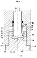
- Fig. 1 shows a longitudinal section of a tool machine spindle and a clamping device arranged therein according to one embodiment of the invention, and more specifically, to the right of the centre line, the device is in its clamped position and to the left of the centre line, the device is in its released position.
- Fig. 2 shows an axial section of another embodiment of the clamping device of the invention wherein the clamping sleeve is axially slotted and composed of vulcanized rubber and metal segments.
- Fig. 3-5 shows sectional views of possible embodiments of locking elements forming part of the clamping device shown in Fig. 2.
- FIG. 10 there is shown a portion of a tool machine spindle 10.
- the spindle 10 is power operated in a conventional way and therefore the means that are used are not shown.
- a shaft portion 12 of a toolholder 13 which is symmetrical about the central axis 11 is received in a corresponding cylindrical bore 14 in the machine spindle 10.
- the shaft portion 12 is intended to carry a tool (not shown) at one end thereof.
- the shaft portion 12 is at its opposite end provided with a cylindrical hole 15 confined by a radial bottom surface 16 and an axially extending hole wall 17 in which an annular recess 18, semi-circular in cross-section, is provided.
- the recess 18 could alternatively have a formation differing from semi-circular.
- the annular recess can be smoothly rounded whilst extending axially.
- Fig. 4-5 there is shown an embodiment where the annular recess 18 has a downward smoothly rounded portion which is elongated but confined axially upwards by an upper radial shoulder 19.
- a clamping device which carries the shaft portion 12 and the toolholder 13 is provided inside the machine spindle, said clamping device comprising a draw bar 20 the lower end of which is provided in form of a radially extended shoulder portion 21.
- a sleeve 23 is provided concentrically around the bar 20, the lower portion of said sleeve 23 being in shape of an annular flange 24 with a circularly rounded profile.
- the sleeve 23 is manufactured of spring steel in a thin section and by having provided a number of axially extending slots around its circumference, said slots extending upwardly from the flange 24 and up to a rear point 25 on the sleeve 23 where the rear portion 26 of said sleeve is somewhat broader in its section than the remainder portion of the sleeve.
- This rear portion 26 has an even thickness and is received with clearance fit in a corresponding recess 27 in the spindle whilst being in abutment against an O-ring 28 located against radial surface 22, said O-ring acting as a tolerance absorbing element.
- the force that is applied to the draw bar 20 is transferred to the shoulder portion 21 by means of the contact that is applied by the annular flange 24 of said sleeve 23 on to the shaft portion 12 in the point 29. There is consequently no transmission of the force F1 to be applied on the draw bar 20.
- the shoulder portion 21 which forces the flange 24 radially outwards and into the annular recess 18 comprises a bevelled surface 30, inclined in relation to the central axis 11, and a radially outer surface 31 that preferably has a circularly rounded formation.
- the bevelled surface 30 is intended to act as a sliding surface and the outer surface 31 is intended to represent an abutment for the flange 24 of the sleeve 23.
- the outer surface 31 has a smoothly rounded profile which as closely as possible matches the profile of said annular flange 24. This ensures the establishment of largest possible contact surface which enables a desirable low surface pressure. It is equally as important that said outer surface 31, said annular flange 24 and the annular recess 18 are made of a hardened material which makes it easier to maintain desired dimensional limitations of the device.
- Fig. 2 there is shown an alternative embodiment of the device in which the clamping sleeve 23 again comprises a lower end portion in the form of a circular extension 24 that is integral with the remainder of said sleeve whereas the upper portion thereof comprises a number of slots distributed around the periphery of the sleeve in which rubber or any other synthetic material is vulcanized.
- rubber portions 32 are firmly vulcanized on to the outer surface of said clamping sleeve along a portion of its length and also provided as rear end portions arranged in abutment with an abutment surface 33 provided radially.
- the outer mantle surface of the shoulder portion 21 has been formed as a cylindrical guiding surface 34 aimed to be guided with clearance fit towards the axially extending hole wall 17 in the hole 15.
- the draw bar 20 is activated by a press force F2 sufficiently large so as to press the bar 20 and its shoulder portion 21 to the position shown to the left of the centre line 11.
- the diameter of the flange 24 is selected such that the shaft portion 12 can be released axially from the draw bar 20 to enable desired exchange of tools.
- the shoulder portion 21 of said draw bar 20 is brought to a position where its end surface comes to abutment with the bottom surface 16 of said hole 15 when the force F2 acts upon the draw bar so that it is brought to its release position as shown to the left of the centre line 11 whereby the draw bar 20 acts as a pushing-out member.
- Fig. 5 there is shown an alternative embodiment wherein the annular recess 18 has the same formation as in Fig. 4.
- the axial abutment for the locking member 24 is provided by a radial abutment 19 whereas the interior surface of the lower portion of the clamping sleeve 23 comes into surface contact with the abutment surface 31 on the shoulder 21, said surface 31 being located outwardly of bevelled surface 30 whilst inclined in relation to the centre line 11.
- the lower end portion of the locking member 24 is made in the form of a radial support surface 35 which is brought in contact with a radial surface 36 on the draw bar 20 which is oriented parallel with an upper support surface 37 intended for abutment against the radial abutment surface 19.
- the tool clamping device has been described when used in a machine spindle with a rotary tool. It is to be understood however that the invention is also useful for the purpose of connecting a stationary turning tool with a correspondingly matching tool machine.
Landscapes
- Engineering & Computer Science (AREA)
- Mechanical Engineering (AREA)
- Gripping On Spindles (AREA)
Description
- The present invention relates to a tool clamping device for machine tools, comprising a draw bar that is axially displaceable inside a machine spindle and a locking element arranged in cooperation with said draw bar, said device carrying a toolholder by exercising a relative movement between the draw bar and the locking element thus effecting a lateral displacement of said locking element into locking engagement with the shaft portion of said toolholder (see e.g. EP-A-0291 048).
- There is an increased demand for tool clamping devices that are reliable in tooling machines. Usually the tool is carried by a conical portion which is aimed to centralize the tool in the spindle and to absorb the radial and axial forces that are acting on the tool. There is also an increased demand for devices that enable tool changes to be made automatically in tooling machines.
- It is therefore a purpose of the present invention to provide a tool clamping device that enables transmission of much larger tensile forces than what is possible with other commercially available devices.
- It is another purpose of the invention to provide a tool clamping device which requires less space than those hitherto available.
- It is another purpose of the invention to provide such a clamping device that enables a short axial displacement of the clamping sleeve in connection with change of tools.
- It is yet another purpose of the invention to provide a clamping device that consists of a few details thus enabling simplified construction of the device.
- These purposes are met with a tool clamping device having the features of claim 1.
- The invention will now be described more in detail in connection with the preferred embodiment illustrated on the enclosed drawings.
- Fig. 1 shows a longitudinal section of a tool machine spindle and a clamping device arranged therein according to one embodiment of the invention, and more specifically, to the right of the centre line, the device is in its clamped position and to the left of the centre line, the device is in its released position.
- Fig. 2 shows an axial section of another embodiment of the clamping device of the invention wherein the clamping sleeve is axially slotted and composed of vulcanized rubber and metal segments.
- Fig. 3-5 shows sectional views of possible embodiments of locking elements forming part of the clamping device shown in Fig. 2.
- In the Figures there is shown a portion of a
tool machine spindle 10. Thespindle 10 is power operated in a conventional way and therefore the means that are used are not shown. Ashaft portion 12 of atoolholder 13 which is symmetrical about thecentral axis 11 is received in a correspondingcylindrical bore 14 in themachine spindle 10. Theshaft portion 12 is intended to carry a tool (not shown) at one end thereof. - The
shaft portion 12 is at its opposite end provided with acylindrical hole 15 confined by aradial bottom surface 16 and an axially extendinghole wall 17 in which anannular recess 18, semi-circular in cross-section, is provided. As shown in Fig. 3-4 therecess 18 could alternatively have a formation differing from semi-circular. As shown in Fig. 3 the annular recess can be smoothly rounded whilst extending axially. In Fig. 4-5 there is shown an embodiment where theannular recess 18 has a downward smoothly rounded portion which is elongated but confined axially upwards by an upperradial shoulder 19. - A clamping device which carries the
shaft portion 12 and thetoolholder 13 is provided inside the machine spindle, said clamping device comprising adraw bar 20 the lower end of which is provided in form of a radially extendedshoulder portion 21. Between a radially providedsurface 22 on the spindle, intended for axial abutment, and theshoulder 21 on the draw bar 20 asleeve 23 is provided concentrically around thebar 20, the lower portion of saidsleeve 23 being in shape of anannular flange 24 with a circularly rounded profile. When the draw bar is subjected to forces in F₁-direction theannular flange 24 is forced radially outwards, due to theshoulder 21, and further into engagement with therecess 18 in theshaft portion 13. This is made possible due to the fact that thesleeve 23 is manufactured of spring steel in a thin section and by having provided a number of axially extending slots around its circumference, said slots extending upwardly from theflange 24 and up to arear point 25 on thesleeve 23 where therear portion 26 of said sleeve is somewhat broader in its section than the remainder portion of the sleeve. Thisrear portion 26 has an even thickness and is received with clearance fit in acorresponding recess 27 in the spindle whilst being in abutment against an O-ring 28 located againstradial surface 22, said O-ring acting as a tolerance absorbing element. - The force that is applied to the
draw bar 20 is transferred to theshoulder portion 21 by means of the contact that is applied by theannular flange 24 of saidsleeve 23 on to theshaft portion 12 in thepoint 29. There is consequently no transmission of the force F₁ to be applied on thedraw bar 20. Theshoulder portion 21 which forces theflange 24 radially outwards and into theannular recess 18 comprises abevelled surface 30, inclined in relation to thecentral axis 11, and a radiallyouter surface 31 that preferably has a circularly rounded formation. Thebevelled surface 30 is intended to act as a sliding surface and theouter surface 31 is intended to represent an abutment for theflange 24 of thesleeve 23. - It is important that the
outer surface 31 has a smoothly rounded profile which as closely as possible matches the profile of saidannular flange 24. This ensures the establishment of largest possible contact surface which enables a desirable low surface pressure. It is equally as important that saidouter surface 31, saidannular flange 24 and theannular recess 18 are made of a hardened material which makes it easier to maintain desired dimensional limitations of the device. - In Fig. 2 there is shown an alternative embodiment of the device in which the
clamping sleeve 23 again comprises a lower end portion in the form of acircular extension 24 that is integral with the remainder of said sleeve whereas the upper portion thereof comprises a number of slots distributed around the periphery of the sleeve in which rubber or any other synthetic material is vulcanized. In additionthereto rubber portions 32 are firmly vulcanized on to the outer surface of said clamping sleeve along a portion of its length and also provided as rear end portions arranged in abutment with anabutment surface 33 provided radially. This enables thesynthetic portion 32 to be expandable when the force F₁ is exerted to thedraw bar 20 in order to have theshaft portion 12 firmly secured to themachine spindle 10. The synthetic material or the rubber will contract the sleeve when the draw bar is subjected to the force F₂. - In order to have the
draw bar 20 in Fig. 1-2 subjected to a good centering and guidance axially in thehole 15 the outer mantle surface of theshoulder portion 21 has been formed as a cylindrical guidingsurface 34 aimed to be guided with clearance fit towards the axially extendinghole wall 17 in thehole 15. When there is a need for change of tools thedraw bar 20 is activated by a press force F₂ sufficiently large so as to press thebar 20 and itsshoulder portion 21 to the position shown to the left of thecentre line 11. The diameter of theflange 24 is selected such that theshaft portion 12 can be released axially from thedraw bar 20 to enable desired exchange of tools. As appears from Fig. 1 and 2 theshoulder portion 21 of saiddraw bar 20 is brought to a position where its end surface comes to abutment with thebottom surface 16 of saidhole 15 when the force F₂ acts upon the draw bar so that it is brought to its release position as shown to the left of thecentre line 11 whereby thedraw bar 20 acts as a pushing-out member. - In Fig. 5 there is shown an alternative embodiment wherein the
annular recess 18 has the same formation as in Fig. 4. Hence, the axial abutment for thelocking member 24 is provided by aradial abutment 19 whereas the interior surface of the lower portion of theclamping sleeve 23 comes into surface contact with theabutment surface 31 on theshoulder 21, saidsurface 31 being located outwardly ofbevelled surface 30 whilst inclined in relation to thecentre line 11. The lower end portion of thelocking member 24 is made in the form of aradial support surface 35 which is brought in contact with aradial surface 36 on thedraw bar 20 which is oriented parallel with anupper support surface 37 intended for abutment against theradial abutment surface 19. - Due to the provision of an axially slotted clamping sleeve as aforesaid wherein rubber segments are vulcanized between metal segments it is ensured that during clamping there is established an elastic outbending radially and that fatigue failure of the material due to outbending of the metal segments is limited to the rubber material in the vulcanized part. Vulcanization by means of rubber can serve the purpose of a collapse-promoting element, i.e. promotes contraction of the sleeve, and to serve as a tolerance absorbing unit. Due to the fact that no force transmission occurs when said
locking sleeve 23 is subject to a relative movement in relation to the locking recess its requirements of tolerance and surface finish are very low and therefore it is not necessary to perform any grinding of tool. - The tool clamping device has been described when used in a machine spindle with a rotary tool. It is to be understood however that the invention is also useful for the purpose of connecting a stationary turning tool with a correspondingly matching tool machine.
Claims (13)
- Tool clamping device for machine tools comprising a draw bar (20) that is axially displaceable inside a machine spindle (10) said draw bar being provided with a radially extending shoulder portion (21) at one end, and a locking element (24) arranged concentrically around said draw bar for the purpose of carrying a shaft portion (12) of a tool holder by exercising a relative movement between the draw bar and the locking element, thus effecting a lateral displacement of said locking element (24) into locking engagement with the shaft portion (12) of said tool holder, characterized in that the shoulder portion of said draw bar is provided as a radially forged shoulder (21) comprising two distinct surface portions (30, 31), and that the locking element consists of a radially expandable clamping sleeve (23) provided around said draw bar provided with an integral annular flange (24) which is received in a cylindrical hole (15) in the shaft portion jointly together with the shoulder portion (21) whereby the draw bar (20) is provided with an inclined bevelled face (30) so as to exert a radial force outwards on to said flange (24) so that the latter, upon axial clamping of said draw bar, is forced into final abutment with a radially outer surface (31) on said draw bar whilst simultaneously engaging with a correspondingly designed annular recess (18) provided in the shaft portion (12) for the clamping thereof, whereby said outer surface (31) has a profile which matches the profile of said flange (24).
- Tool clamping device as defined in claim 1, characterized in that the clamping sleeve (23) is radially expandable by being provided with axially extending slots distributed around its circumference, said slots extending along a major portion of the length of said sleeve.
- Tool clamping device as defined in claim 1 characterized in that the annular recess (18) is provided with circular cross-section, and that the annular flange (24) has a corresponding formation.
- Tool clamping device as defined in claim 1, characterized in that the annular flange (24) of the clamping sleeve and the shoulder portion (21) of said draw bar are received in a counterbore (15) of such depth that the end surface of the draw bar comes into abutment with the radial bottom surface (16) of said counterbore (15) when the draw bar is displaced into its release position.
- Tool clamping device as defined in claim 2, characterized in that the rear portion of said sleeve (23) has a number of axial slots around its circumference in which portions (32) of rubber or other synthetic material is vulcanized whereby said rubber portions (32) also extend axially beyond said sleeve so as to provide a rear end portion for abutment against a radially provided surface (22) in the spindle (10).
- Tool clamping device as defined in claim 1, characterized in that the rear portion (26) of said sleeve (23) has a wider cross-section than the remainder of the sleeve whilst being received with clearance fit in a corresponding recess (27) in the shoulder in axial abutment with an O-ring (28) of rubber.
- Tool clamping device as defined in any of the claims 1-6, characterized in that the integral shoulder (21) of the draw bar (20) is received in a cylindrical hole (15) of such diameter that the clamping sleeve (23) becomes radially expandable in the annular space between the hole wall (17) and the mantle surface of the draw bar.
- Tool clamping device as defined in any of the claims 1-7, characterized in that the outer mantle surface of the shoulder (21) is in the shape of a cylindrical guiding surface (34) provided to be slidable with clearance fit towards the hole wall (17).
- Tool clamping device as defined in any of the claims 1-8, characterized in that the flange (24) and the annular recess (18) are axially elongated whilst having a smoothly rounded mantle surface.
- Tool clamping device as defined in any of the claims 1-9, characterized in that the annular recess (18) is elongated and comprises an axially forward rounded portion and a rear end portion in the form of a radial shoulder (19) whereby the flange (24) has a complementary shape.
- Tool clamping device as defined in claim 10, characterized in that the abutment surface (31) that is located outwardly of the bevelled surface (30) is inclined whereby the interior surface of the lower portion of the annular flange (24) is provided at a correspondingly inclined angle.
- Tool clamping device as defined in claim 11, characterized in that the abutment surface (31) is inclined at an angle in relation to the centre line (11) that is smaller than the inclination angle of the radially inner bevelled face (30).
- Tool clamping device as defined in claim 9, characterized in that the lower and upper end portions of the annular flange (24) are in the shape of radially provided surfaces (35) and (37) respectively, the lower radial surface (35) being arranged for abutment against a radial surface (36) on the draw bar (20) whereby the radial surface (36) on said draw bar is located adjacent to and intersects with the axially extending guide surface (34) on said draw bar.
Applications Claiming Priority (2)
| Application Number | Priority Date | Filing Date | Title |
|---|---|---|---|
| SE8900808A SE468631B (en) | 1989-03-08 | 1989-03-08 | TOOL COUPLING WITH RADIALLY RELEASABLE LOCKING ELEMENT CONNECTING WITH A TOUCH BAR |
| SE8900808 | 1989-03-08 |
Publications (3)
| Publication Number | Publication Date |
|---|---|
| EP0387228A2 EP0387228A2 (en) | 1990-09-12 |
| EP0387228A3 EP0387228A3 (en) | 1991-04-03 |
| EP0387228B1 true EP0387228B1 (en) | 1994-05-11 |
Family
ID=20375274
Family Applications (1)
| Application Number | Title | Priority Date | Filing Date |
|---|---|---|---|
| EP90850097A Expired - Lifetime EP0387228B1 (en) | 1989-03-08 | 1990-03-06 | Tool coupling between a toolholder and a machine spindle |
Country Status (5)
| Country | Link |
|---|---|
| US (1) | US4978262A (en) |
| EP (1) | EP0387228B1 (en) |
| JP (1) | JPH02298404A (en) |
| DE (1) | DE69008758T2 (en) |
| SE (1) | SE468631B (en) |
Families Citing this family (13)
| Publication number | Priority date | Publication date | Assignee | Title |
|---|---|---|---|---|
| US5193954A (en) * | 1991-10-30 | 1993-03-16 | Gte Valenite Corporation | Universal tool connection |
| DE4303608A1 (en) * | 1993-02-09 | 1994-08-11 | Kelch & Co Werkzeugmaschf | Clamping device for a tool |
| US5466102A (en) * | 1993-12-16 | 1995-11-14 | Kennametal Inc. | System for coupling machine tools |
| DE19548711A1 (en) * | 1995-12-23 | 1997-07-03 | Klement Klaus Dieter | Interface between a tool carrier and a clamping shank of a machine tool |
| DE19600089A1 (en) * | 1996-01-03 | 1997-07-10 | Klement Klaus Dieter | Clamping device for fastening a tool holder to a spindle of a machine tool |
| DE19753663A1 (en) * | 1997-12-03 | 1999-06-17 | Guehring Joerg Dr | Clamping system for the detachable connection of two parts |
| US6299394B1 (en) * | 2000-02-28 | 2001-10-09 | Stojan Stojanovski | Milling tool holder |
| DE10059209A1 (en) * | 2000-11-29 | 2002-06-13 | Roehm Gmbh | Clamping device for a hollow shaft |
| KR100441953B1 (en) * | 2001-12-22 | 2004-07-27 | 위아 주식회사 | a wedge type hollow spindle shaft pot for a ATC |
| DE102005030820B3 (en) * | 2005-07-01 | 2006-08-17 | Ott-Jakob Gmbh & Co. Spanntechnik Kg | Tensioning device e.g. for removable connection of two machine parts, has machine part having clamping unit and cooperating counterpart in second machine part with unit having axially adjustable clamping element and plier elements |
| CH704891A1 (en) * | 2011-05-03 | 2012-11-15 | Rego Fix Ag | Clamping system for use during cutting or milling workpiece, has holding crown unit screwed into sleeve and engaged with tool by inserting tool into recess formed on shaft, where sleeve is frictionally and form-fittingly connected with tool |
| CN102658574A (en) * | 2012-05-31 | 2012-09-12 | 四川农业大学 | Cypress defatting method |
| DE102014101003B4 (en) * | 2014-01-28 | 2015-11-05 | Schenck Rotec Gmbh | Recording device for a rotatable spindle of a balancing machine |
Family Cites Families (14)
| Publication number | Priority date | Publication date | Assignee | Title |
|---|---|---|---|---|
| DE1402301B2 (en) * | 1957-04-20 | 1971-08-19 | Wollenhaupt, Jakob, 5630 Remscheid Hasten | DEVICE FOR SETTING THE BEARING AND CLAMPING TOOLS TOOL CARRIERS WORKPIECES AND WORKPIECE CARRIERS ON MACHINE TOOLS |
| FR2068130A5 (en) * | 1969-11-28 | 1971-08-20 | Tiraspolsky Wladimir | |
| JPS51126586A (en) * | 1975-04-28 | 1976-11-04 | Toyoda Mach Works Ltd | Device for stopping the spindle of turret type machining center in fix ed phase |
| US4226562A (en) * | 1977-09-16 | 1980-10-07 | Schmid-Kosta Kg | Toolholder |
| IT1124440B (en) * | 1979-07-10 | 1986-05-07 | Benatti Edmo | TIE-ROD DEVICE WITH EXPANDABLE PLIERS FOR THE LOCKING OF THE TOOL HOLDER IN THE SPINDLE OF MILLING MACHINES AND SIMILAR |
| DE3007440A1 (en) * | 1980-02-28 | 1981-09-17 | Fried. Krupp Gmbh, 4300 Essen | TOOL SETUP WITH INTERCHANGEABLE TOOL HOLDER |
| US4565476A (en) * | 1984-01-16 | 1986-01-21 | General Dynamics Corporation | Internal hydraulic clamp |
| US4589808A (en) * | 1984-11-16 | 1986-05-20 | Lesnor Maehr Manufacturing Corp. | Power draw bar |
| DE3509922C1 (en) * | 1985-03-19 | 1986-06-19 | Carl Hurth Maschinen- und Zahnradfabrik GmbH & Co, 8000 München | Clamping device for fastening a work holder or the like to a spindle |
| SE454488B (en) * | 1986-10-31 | 1988-05-09 | Seco Tools Ab | PROCEDURE AND APPARATUS FOR ASTADCOMMATING THE CONNECTION OF A HALLER BODY WITH A TOOL HEAD |
| DE8816782U1 (en) * | 1987-05-11 | 1990-06-21 | Gühring oHG, 72458 Albstadt | Coupling device between a workpiece or tool carrier part and a handling device provided for it |
| US4844671A (en) * | 1987-05-11 | 1989-07-04 | Gottlieb Guhring Kg | Coupling device |
| US4764064A (en) * | 1987-09-25 | 1988-08-16 | Komo Machine Incorporated | Tool changer |
| DE8805690U1 (en) * | 1988-04-29 | 1989-08-31 | A. Ott Gmbh, 8960 Kempten | Clamping device for axial clamping of two detachable machine parts |
-
1989
- 1989-03-08 SE SE8900808A patent/SE468631B/en not_active IP Right Cessation
-
1990
- 1990-03-06 EP EP90850097A patent/EP0387228B1/en not_active Expired - Lifetime
- 1990-03-06 DE DE69008758T patent/DE69008758T2/en not_active Expired - Fee Related
- 1990-03-06 US US07/488,996 patent/US4978262A/en not_active Expired - Fee Related
- 1990-03-08 JP JP2055172A patent/JPH02298404A/en active Pending
Also Published As
| Publication number | Publication date |
|---|---|
| SE8900808D0 (en) | 1989-03-08 |
| DE69008758T2 (en) | 1994-08-25 |
| JPH02298404A (en) | 1990-12-10 |
| SE468631B (en) | 1993-02-22 |
| US4978262A (en) | 1990-12-18 |
| DE69008758D1 (en) | 1994-06-16 |
| SE8900808L (en) | 1990-09-09 |
| EP0387228A2 (en) | 1990-09-12 |
| EP0387228A3 (en) | 1991-04-03 |
Similar Documents
| Publication | Publication Date | Title |
|---|---|---|
| US6077003A (en) | Tool holder | |
| US6386789B1 (en) | Quick release ball type locking pin and production tool | |
| EP0387228A2 (en) | Tool coupling between a toolholder and a machine spindle | |
| US4997325A (en) | Chuck for axially clamping two machine parts which are releasable from each other | |
| FI77598C (en) | VERKTYGSHAOLLARE FOER BORR- OCH MEJSELVERKTYG. | |
| US5447397A (en) | Apparatus for fixing an annular cutter to an arbor | |
| US4954004A (en) | Coupling device between two elements | |
| US20040255444A1 (en) | Pressing device | |
| EP3546098B1 (en) | Quick changeable collet clamping assembly | |
| US5667228A (en) | Quick change mandrel for an engine lathe etc | |
| WO1998032563A1 (en) | Hydromechanical chuck | |
| GB1566593A (en) | Clamping device for the support of annular workpieces for internal machining | |
| JP2005511325A (en) | Clamping device | |
| EP0383735B1 (en) | Tool clamping device | |
| WO1997031740A2 (en) | Counter centrifugal chuck and mounting systems | |
| US6932358B1 (en) | Quick change endform tool cartridge | |
| US4777714A (en) | Quick-change mount for chucks | |
| US4141263A (en) | Device for the centered clamping of annular workpieces | |
| GB2100627A (en) | Clamping sleeve for gripping tool or workpiece | |
| GB2037192A (en) | Mandrel/collet chuck | |
| US2859041A (en) | Collet chucks | |
| EP0134988B1 (en) | Collet for automatic lathes | |
| US5556114A (en) | Hydraulic expanding and contracting mandrel | |
| US5192086A (en) | Double ramp, full length grip collet | |
| US4632407A (en) | Inside/outside chucking device |
Legal Events
| Date | Code | Title | Description |
|---|---|---|---|
| PUAI | Public reference made under article 153(3) epc to a published international application that has entered the european phase |
Free format text: ORIGINAL CODE: 0009012 |
|
| AK | Designated contracting states |
Kind code of ref document: A2 Designated state(s): DE FR GB IT SE |
|
| PUAL | Search report despatched |
Free format text: ORIGINAL CODE: 0009013 |
|
| AK | Designated contracting states |
Kind code of ref document: A3 Designated state(s): DE FR GB IT SE |
|
| 17P | Request for examination filed |
Effective date: 19910923 |
|
| 17Q | First examination report despatched |
Effective date: 19930521 |
|
| GRAA | (expected) grant |
Free format text: ORIGINAL CODE: 0009210 |
|
| AK | Designated contracting states |
Kind code of ref document: B1 Designated state(s): DE FR GB IT SE |
|
| PG25 | Lapsed in a contracting state [announced via postgrant information from national office to epo] |
Ref country code: SE Free format text: THE PATENT HAS BEEN ANNULLED BY A DECISION OF A NATIONAL AUTHORITY Effective date: 19940511 |
|
| ITF | It: translation for a ep patent filed | ||
| REF | Corresponds to: |
Ref document number: 69008758 Country of ref document: DE Date of ref document: 19940616 |
|
| ET | Fr: translation filed | ||
| PLBE | No opposition filed within time limit |
Free format text: ORIGINAL CODE: 0009261 |
|
| STAA | Information on the status of an ep patent application or granted ep patent |
Free format text: STATUS: NO OPPOSITION FILED WITHIN TIME LIMIT |
|
| 26N | No opposition filed | ||
| PGFP | Annual fee paid to national office [announced via postgrant information from national office to epo] |
Ref country code: GB Payment date: 20010228 Year of fee payment: 12 Ref country code: DE Payment date: 20010228 Year of fee payment: 12 |
|
| PGFP | Annual fee paid to national office [announced via postgrant information from national office to epo] |
Ref country code: FR Payment date: 20010313 Year of fee payment: 12 |
|
| REG | Reference to a national code |
Ref country code: GB Ref legal event code: IF02 |
|
| PG25 | Lapsed in a contracting state [announced via postgrant information from national office to epo] |
Ref country code: GB Free format text: LAPSE BECAUSE OF NON-PAYMENT OF DUE FEES Effective date: 20020306 |
|
| PG25 | Lapsed in a contracting state [announced via postgrant information from national office to epo] |
Ref country code: DE Free format text: LAPSE BECAUSE OF NON-PAYMENT OF DUE FEES Effective date: 20021001 |
|
| GBPC | Gb: european patent ceased through non-payment of renewal fee |
Effective date: 20020306 |
|
| PG25 | Lapsed in a contracting state [announced via postgrant information from national office to epo] |
Ref country code: FR Free format text: LAPSE BECAUSE OF NON-PAYMENT OF DUE FEES Effective date: 20021129 |
|
| REG | Reference to a national code |
Ref country code: FR Ref legal event code: ST |
|
| PG25 | Lapsed in a contracting state [announced via postgrant information from national office to epo] |
Ref country code: IT Free format text: LAPSE BECAUSE OF NON-PAYMENT OF DUE FEES;WARNING: LAPSES OF ITALIAN PATENTS WITH EFFECTIVE DATE BEFORE 2007 MAY HAVE OCCURRED AT ANY TIME BEFORE 2007. THE CORRECT EFFECTIVE DATE MAY BE DIFFERENT FROM THE ONE RECORDED. Effective date: 20050306 |