EP0385502B1 - Electric power transmitting device with inductive coupling - Google Patents
Electric power transmitting device with inductive coupling Download PDFInfo
- Publication number
- EP0385502B1 EP0385502B1 EP90104113A EP90104113A EP0385502B1 EP 0385502 B1 EP0385502 B1 EP 0385502B1 EP 90104113 A EP90104113 A EP 90104113A EP 90104113 A EP90104113 A EP 90104113A EP 0385502 B1 EP0385502 B1 EP 0385502B1
- Authority
- EP
- European Patent Office
- Prior art keywords
- coil
- groove
- grip
- coils
- electric power
- Prior art date
- Legal status (The legal status is an assumption and is not a legal conclusion. Google has not performed a legal analysis and makes no representation as to the accuracy of the status listed.)
- Expired - Lifetime
Links
Images
Classifications
-
- G—PHYSICS
- G06—COMPUTING OR CALCULATING; COUNTING
- G06K—GRAPHICAL DATA READING; PRESENTATION OF DATA; RECORD CARRIERS; HANDLING RECORD CARRIERS
- G06K7/00—Methods or arrangements for sensing record carriers, e.g. for reading patterns
- G06K7/10—Methods or arrangements for sensing record carriers, e.g. for reading patterns by electromagnetic radiation, e.g. optical sensing; by corpuscular radiation
- G06K7/10544—Methods or arrangements for sensing record carriers, e.g. for reading patterns by electromagnetic radiation, e.g. optical sensing; by corpuscular radiation by scanning of the records by radiation in the optical part of the electromagnetic spectrum
- G06K7/10821—Methods or arrangements for sensing record carriers, e.g. for reading patterns by electromagnetic radiation, e.g. optical sensing; by corpuscular radiation by scanning of the records by radiation in the optical part of the electromagnetic spectrum further details of bar or optical code scanning devices
- G06K7/10881—Methods or arrangements for sensing record carriers, e.g. for reading patterns by electromagnetic radiation, e.g. optical sensing; by corpuscular radiation by scanning of the records by radiation in the optical part of the electromagnetic spectrum further details of bar or optical code scanning devices constructional details of hand-held scanners
-
- H—ELECTRICITY
- H02—GENERATION; CONVERSION OR DISTRIBUTION OF ELECTRIC POWER
- H02J—ELECTRIC POWER NETWORKS; CIRCUIT ARRANGEMENTS OR SYSTEMS FOR SUPPLYING OR DISTRIBUTING ELECTRIC POWER; SYSTEMS FOR STORING ELECTRIC ENERGY
- H02J50/00—Circuit arrangements or systems for wireless supply or distribution of electric power
- H02J50/10—Circuit arrangements or systems for wireless supply or distribution of electric power using inductive coupling
-
- H—ELECTRICITY
- H02—GENERATION; CONVERSION OR DISTRIBUTION OF ELECTRIC POWER
- H02J—ELECTRIC POWER NETWORKS; CIRCUIT ARRANGEMENTS OR SYSTEMS FOR SUPPLYING OR DISTRIBUTING ELECTRIC POWER; SYSTEMS FOR STORING ELECTRIC ENERGY
- H02J50/00—Circuit arrangements or systems for wireless supply or distribution of electric power
- H02J50/005—Mechanical details of housing or structure aiming to accommodate the power transfer means, e.g. mechanical integration of coils, antennas or transducers into emitting or receiving devices
-
- H—ELECTRICITY
- H02—GENERATION; CONVERSION OR DISTRIBUTION OF ELECTRIC POWER
- H02J—ELECTRIC POWER NETWORKS; CIRCUIT ARRANGEMENTS OR SYSTEMS FOR SUPPLYING OR DISTRIBUTING ELECTRIC POWER; SYSTEMS FOR STORING ELECTRIC ENERGY
- H02J7/00—Circuit arrangements for charging or discharging batteries or for supplying loads from batteries
- H02J7/70—Circuit arrangements for charging or discharging batteries or for supplying loads from batteries characterised by the mechanical construction
- H02J7/731—Circuit arrangements for charging or discharging batteries or for supplying loads from batteries characterised by the mechanical construction specially adapted for holding portable devices containing batteries
-
- Y—GENERAL TAGGING OF NEW TECHNOLOGICAL DEVELOPMENTS; GENERAL TAGGING OF CROSS-SECTIONAL TECHNOLOGIES SPANNING OVER SEVERAL SECTIONS OF THE IPC; TECHNICAL SUBJECTS COVERED BY FORMER USPC CROSS-REFERENCE ART COLLECTIONS [XRACs] AND DIGESTS
- Y10—TECHNICAL SUBJECTS COVERED BY FORMER USPC
- Y10S—TECHNICAL SUBJECTS COVERED BY FORMER USPC CROSS-REFERENCE ART COLLECTIONS [XRACs] AND DIGESTS
- Y10S336/00—Inductor devices
- Y10S336/02—Separable
-
- Y—GENERAL TAGGING OF NEW TECHNOLOGICAL DEVELOPMENTS; GENERAL TAGGING OF CROSS-SECTIONAL TECHNOLOGIES SPANNING OVER SEVERAL SECTIONS OF THE IPC; TECHNICAL SUBJECTS COVERED BY FORMER USPC CROSS-REFERENCE ART COLLECTIONS [XRACs] AND DIGESTS
- Y10—TECHNICAL SUBJECTS COVERED BY FORMER USPC
- Y10S—TECHNICAL SUBJECTS COVERED BY FORMER USPC CROSS-REFERENCE ART COLLECTIONS [XRACs] AND DIGESTS
- Y10S439/00—Electrical connectors
- Y10S439/95—Electrical connector adapted to transmit electricity to mating connector without physical contact, e.g. by induction, magnetism, or electrostatic field
Definitions
- Still another object of the present invention is to provide a manually operable device which can be supplied with electric power through an inductive coupling provided by primary and secondary coils, and which can be manipulated with ease without any substantial loss in the efficiency of electric power transmission.
- FIG. 2 shows an electric power transmitting device according to a first embodiment of the present invention, which employs such primary and secondary coils 402, 403.
- the electric power transmitting device shown in FIG. 2 is incorporated in a bar-code reader which comprises a gun-shaped, hand-held bar-code scanner 505 and a holder 503 for holding the bar-code scanner 505.
- the bar-code scanner 505 includes a handle or grip 507 which houses therein the secondary coil 402, a rectifier unit (not shown), and a power supply unit 506 comprising a secondary battery.
- the holder 503 houses therein the primary coil 401 and an electric power transmitter 504.
Landscapes
- Engineering & Computer Science (AREA)
- Physics & Mathematics (AREA)
- Electromagnetism (AREA)
- General Health & Medical Sciences (AREA)
- Power Engineering (AREA)
- Health & Medical Sciences (AREA)
- Computer Networks & Wireless Communication (AREA)
- Toxicology (AREA)
- Artificial Intelligence (AREA)
- Computer Vision & Pattern Recognition (AREA)
- General Physics & Mathematics (AREA)
- Theoretical Computer Science (AREA)
- Charge And Discharge Circuits For Batteries Or The Like (AREA)
- Near-Field Transmission Systems (AREA)
Description
- The present invention relates to an electric power transmitting device having a pair of coils for transmitting electric power through an inductive coupling.
- One known electric power transmitting device having a pair of coils is disclosed in Japanese Laid-Open Patent Publication No. 62(1987)-260526.
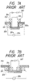
- As shown in FIG. 7A of the accompanying drawings, the known device includes a
case 201 having arecess 201a and acase 202 having aprojection 202a with acore 205 disposed therein. Aprimary coil 203 is disposed around therecess 201a and connected to anAC power supply 206, and asecondary coil 204 is connected to asecondary battery 207. When thecore 205 is inserted through both theprimary coil 203 and thesecondary coil 204, the primary andsecondary coils secondary battery 207 is charged by electric power supplied from theAC power supply 206 through an inductive coupling provided by thecoils - It has also been proposed to position the
secondary coil 204 within theprimary coil 203 for a sufficient efficiency of electric power transmission therebetween, as illustrated in FIG. 7B. - The
cases recess 201a and theprojection 202a have to be formed in and on therespective cases projection 202a on thecase 202 requires a sufficient mechanical strength against possible damage due to impacts. - If the
case 202 in which thesecondary battery 207 is constructed as a grip, then the electric power transmitting device cannot easily be handled since thecore 205 or thesecondary coil 204 can only be inserted in the axial direction of theprimary coil 203. Therefore, the user may tend to feel awkward to magnetically couple the primary andsecondary coils secondary battery 207. Accordingly, thesecondary battery 207 is highly likely to be used up and not charged. - In view of the aforesaid drawbacks of the conventional electric power transmitting device, it is an object of the present invention to provide an electric power transmitting device which include primary and secondary coils that can easily be positioned relatively to each other for an intensive magnetic or inductive coupling.
- Another object of the present invention is to provide an electric power transmitting device having primary and secondary coils which are disposed in one plane for the transmission of electric power therebetween through an inductive coupling, and which can be manipulated with greater freedom without any substantial loss in the efficiency of electric power transmission.
- Still another object of the present invention is to provide a manually operable device which can be supplied with electric power through an inductive coupling provided by primary and secondary coils, and which can be manipulated with ease without any substantial loss in the efficiency of electric power transmission.
- Yet another object of the present invention is to provide a gun-shaped, hand-held bar-code scanner which can be supplied with electric power through an inductive coupling provided by primary and secondary coils, and which can be manipulated with ease without any substantial loss in the efficiency of electric power transmission.
- According to a first aspect of the present invention which is specified in
claim 1, an electric power transmitting device includes a pair of coils which provide a electromagnetic or inductive coupling. One of the coils has a portion bent in the axial direction of the coil. The other coil can be inserted into said one coil not only the axial direction of said one coil, but also a direction transverse to the axial direction through the bent portion of the coil so that, when a component housing said one coil is to be fitted into another component housing the other coil, it can be manipulated easily with great freedom. When said one coil is inserted into the other coil, they are disposed in substantially one plane for an intensive inductive coupling therebetween. - Other aspects of the invention are defined in claims 5 and 8.
- The above and other objects, features and advantages of the present invention will become more apparent from the following description when taken in conjunction with the accompanying drawings in which preferred embodiments of the present invention are shown by way of illustrative example.
-
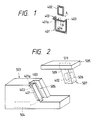
- FIG. 1 is a perspective view schematically showing the principles of the present invention;
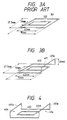
- FIG. 2 is a perspective view of an electric power transmitting device according to a first embodiment of the present invention;
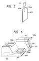
- FIGS. 3A and 3B are perspective views of the primary and secondary coils of a conventional electric power transmitting device and the primary and secondary coils of the first embodiment of the invention, respectively;
- FIG. 4 is a perspective view of the primary and secondary coils of an electric power transmitting device according to a second embodiment of the present invention;
- FIG. 5 is a perspective view of the primary and secondary coils of an electric power transmitting device according to a third embodiment of the present invention; and
- FIG. 6 is a perspective view of an electric power transmitting device according to a fourth embodiment of the present invention.
- Like or corresponding parts are denoted by like or corresponding reference numerals throughout views.
- FIG. 1 schematically shows a basic coil arrangement according to the present invention. In FIG. 1, a
primary coil 401 is of a substantially rectangular shape and has onelongitudinal end 401a bent at a right angle in a direction parallel to the axial direction of theprimary coil 401, i.e., the direction normal to the plane of theprimary coil 401. Thebent end 401a of theprimary coil 401 defines an opening 404. Asecondary coil 402 is also rectangular in shape and smaller than theprimary coil 402. When thesecondary coil 402 is to be combined with theprimary coil 401 for a magnetic or inductive coupling, thesecondary coil 402 can be inserted into theprimary coil 401 in the direction indicated by the arrow A or through theopening 404 in the direction indicated by the arrow B. - FIG. 2 shows an electric power transmitting device according to a first embodiment of the present invention, which employs such primary and
secondary coils code scanner 505 and aholder 503 for holding the bar-code scanner 505. The bar-code scanner 505 includes a handle orgrip 507 which houses therein thesecondary coil 402, a rectifier unit (not shown), and apower supply unit 506 comprising a secondary battery. Theholder 503 houses therein theprimary coil 401 and anelectric power transmitter 504. - The
electric power transmitter 504 supplies theprimary coil 401 with an electric current, such as an alternating current, whose magnitude varies with time. When theprimary coil 401 is supplied with such an electric current, the number of magnetic fluxes in a magnetic field generated by theprimary coil 401 varies, and hence thesecondary coil 402 which is electromagnetically coupled to theprimary coil 401 induces electromotive forces. Therefore, an electric current corresponding to the induced electromagnetic forces flows through thesecondary coil 402, thereby supplying electric power to thepower supply unit 506 to charge the secondary battery. Theelectric power transmitter 504 includes a controller for detecting the charged condition of the secondary battery, and reducing the changes in the magnitude of the current supplied to theprimary coil 401 when it is detected that the secondary battery is fully charged, so that the magnitude of electric power supplied to thepower supply unit 506 will be reduced. The controller of theelectric power transmitter 504 can also detect whether the bar-code scanner 505 is placed on theholder 503 or not. Theelectric power transmitter 504 supplies the current to theprimary coil 401 only when the bar-code scanner 505 is put on theholder 503. - The
secondary battery 506 serves to supply electric power to anelectric component 511 in the bar-code scanner 505. Theelectric component 511 may comprise, for example, a laser diode, a scanning mirror drive motor, and an associated electric circuit. Therefore, the bar-code scanner 505 is of a cordless arrangement and can be energized by the self-contained power supply, i.e., thesecondary battery 506. - The
grip 507 of the bar-code scanner 505 has a frontouter wall 509. Thesecondary coil 402 which is housed in thegrip 507 is disposed parallel and adjacent to the frontouter wall 509. Theholder 503 has an obliquelyvertical groove 505 which is shaped to receive a front portion of thegrip 507. Theprimary coil 401 which is housed in theholder 503 is positioned along thegroove 505 with thebent end 401a extending transversely around thegroove 505 near its upper end. When thegrip 507 is placed in thegroove 505, theprimary coil 401 and thesecondary coil 402 are disposed in one plane lying parallel to the longitudinal axis of thegroove 505. Since theprimary coil 401 has thebent end 401a, as shown in FIGS. 1 and 2, thesecondary coil 402 can be inserted into theprimary coil 401 in the axial direction of theprimary coil 401, i.e., in the direction normal to the longitudinal axis of thegroove 505, and also in the direction normal to the axial direction of theprimary coil 401, i.e., in the direction parallel to the longitudinal axis of thegroove 505. Accordingly, the bar-code scanner 505 can easily be manipulated when it is to be placed on or picked up from theholder 503. Thegroove 505 of theholder 503 is not deep enough to fully accommodate thegrip 507 as shown in FIG. 2. Therefore, thegrip 507 can easily be inserted into and removed from thegroove 505. In addition, theholder 503 can simply be designed and manufactured. - FIG. 3A shows the primary and
secondary coils secondary coils bent end 401a of theprimary coil 401 shown in FIGS. 1 and 2 may have on the efficiency of electric power transmission. Theprimary coil 301 shown in FIG. 3A had a length of 90 mm, a width of 37.5 mm, a wire diameter of 0.5 mm, and 60 turns, whereas thesecondary coil 302 had a length of 42 mm, a width of 19 mm, a wire diameter of 0.2 mm, and 100 turns. The primary andsecondary coils coils bent end 401a of theprimary coil 401 is 70 mm spaced from the other ends The results of the test indicated that the efficiencies of electric power transmission of the conventional and inventive coils were about 15 % and not appreciably different from each other. - FIG. 4 shows the primary and secondary coils of an electric power transmitting device according to a second embodiment of the present invention. The primary coil, denoted at 401A, has two opposite bent ends 401a which define
respective openings 404 parallel to each other. Therefore, thesecondary coil 402 can be inserted into theprimary coil 401A through theopenings 404 in any of the two directions normal to the axis of theprimary coil 401A. Therefore, thesecondary coil 402 can be inserted into theprimary coil 401A with greater freedom as to the directions in which it is inserted, and can be manipulated more easily. - In the first and second embodiments, the
secondary coil 402 is inserted into theprimary coil openings 404 of theprimary coil - According to a third embodiment shown in FIG. 5, one end of a primary coil 404B has an arcuately
curved end 401b defining an arcuate opening 404a through which thesecondary coil 402 can be inserted into theprimary coil 401B. - FIG. 6 shows an electric power transmitting device according to a fourth embodiment of the invention. The electric power transmitting device shown in FIG. 6 includes a gun-shaped, hand-held bar-
code scanner 505A having agrip 507 which houses therein asecondary coil 402 disposed on the bottom thereof. The electric power transmitting device also has aholder 503A having ahorizontal groove 505A for receiving a lower portion of thegrip 507. Aprimary coil 401 is housed in theholder 503A and disposed along thegroove 505A with itsbend end 401a extending transversely around thegroove 505A near one end thereof. - Although certain preferred embodiments have been shown and described, it should be understood that many changes and modifications may be made therein without departing from the scope of the appended claims.
Claims (10)
- An electric power transmitting device comprising:
a first coil (401; 401A; 401B);
a second coil(402) which can be combined with said first coil to provide an inductive coupling therebetween;
means (504) for supplying a current which is variable in magnitude with time to said first coil to induce an electric current across said second coil through said inductive coupling;
wherein said first and second coils can be disposed in substantially one plane ;
characterised in that :
one of said first and second coils has at least one portion (401a; 401b) bent in the axial direction of said one of the coils;
the other of said first and second coils can be inserted into said one of the coils through said bent portion; and
said other of the coils can be moved into and out of said one of the coils in the axial direction of said one of the coils and in a direction transverse to said axial direction. - An electric power transmitting device according to claim 1, wherein said one (401; 401A) of the coils is of a rectangular shape, said bent portion (401a) being on one longitudinal end of said one coil.
- An electric power transmitting device according to claim 2, wherein said one (401A) of the coils has another portion (401a) bent in the axial direction of said one of the coils, said other bent portion being on another longitudinal end of said one coil.
- An electric power transmitting device according to claim 1, wherein said bent portion (401b) comprises an arcuately curved portion.
- A manually operable device and holder combination comprising:
a manually operable device (505; 505A)
a first coil (402) disposed in said manually operable device;
a secondary battery (506) disposed in said manually operable device and electrically chargeable by an electric current induced across said first coil;
a holder (503 ; 503A) for holding said manually operable device;
means defining a groove (505, 505A) in said holder, said manually operable device being insertable into said groove in two substantially perpendicular directions;
a second coil (401) disposed in said holder along said groove, said second coil having a bent portion (401a) extending transverse around said groove, said bent portion being bent in the axial direction of said second coil, which axial direction corresponds to one of said two substantially perpendicular directions; and
an electric power transmitter (504) for supplying said second coil with an electric current which varies in magnitude with time. - A manually operable device and holder combination according to claim 5, wherein said manually operable device (505) includes a grip (507), said first coil (402) being housed in said grip and disposed along a side surface (509) thereof, said groove (505) extending obliquely vertically for receiving said side surface (509) of the grip, said bent portion (401a) being disposed near one end of said groove.
- A manually operable device and holder combination according to claim 5, wherein said manually operable device (505A) includes a grip (507), said first coil (402) being housed in said grip and disposed along a bottom surface thereof, said groove (505A) extending horizontally for receiving said bottom surface of the grip, said bent portion (401a) being disposed near one end of said groove.
- A hand-held bar-code scanner and holder combination comprising:
a gun-shaped hand-held bar-code scanner (505; 505A) having a grip (507);
a first coil (402) disposed in said grip of the bar-code scanner;
a secondary battery (506) disposed in said bar-code scanner and electrically chargeable by an electric current induced across said first coil;
a holder (503; 503A) for holding said grip of the bar-code scanner;
means defining a groove (505; 505A) in said holder, said grip of the bar-code scanner being insertable into said groove in at least two substantially perpendicular directions;
a second coil (401) disposed in said holder along said groove said second coil having a bent portion (401a) extending transverse around said groove, said bent portion being bent in the axial direction of said second coil, which axial direction corresponds to one of said two substantially perpendicular directions;
an electric power transmitter (504) for supplying said second coil with an electric current which varies in magnitude with time; and
wherein said first and second coils are positioned in substantially one plane when said grip is received in said groove. - A hand-held bar-code scanner and holder combination according to claim 8, wherein said first coil (402) is disposed along a side surface (509) of said grip (507), said groove (505) extending obliquely vertically for receiving said side surface of the grip, said bent portion (401a) being disposed near one end of said groove.
- A hand-held bar-code scanner and holder combination according to claim 8, wherein said first coil (402) is disposed along a bottom surface of said grip (507), said groove (505A) extending horizontally for receiving said bottom surface of the grip, said bent portion (401a) being disposed near one end of said groove.
Applications Claiming Priority (2)
| Application Number | Priority Date | Filing Date | Title |
|---|---|---|---|
| JP50544/89 | 1989-03-02 | ||
| JP1050544A JP2820706B2 (en) | 1989-03-02 | 1989-03-02 | Power supply device having coil for electromagnetic coupling |
Publications (3)
| Publication Number | Publication Date |
|---|---|
| EP0385502A2 EP0385502A2 (en) | 1990-09-05 |
| EP0385502A3 EP0385502A3 (en) | 1991-10-09 |
| EP0385502B1 true EP0385502B1 (en) | 1994-10-12 |
Family
ID=12861953
Family Applications (1)
| Application Number | Title | Priority Date | Filing Date |
|---|---|---|---|
| EP90104113A Expired - Lifetime EP0385502B1 (en) | 1989-03-02 | 1990-03-02 | Electric power transmitting device with inductive coupling |
Country Status (4)
| Country | Link |
|---|---|
| US (1) | US5070293A (en) |
| EP (1) | EP0385502B1 (en) |
| JP (1) | JP2820706B2 (en) |
| DE (1) | DE69013185T2 (en) |
Families Citing this family (175)
| Publication number | Priority date | Publication date | Assignee | Title |
|---|---|---|---|---|
| US5625180A (en) * | 1987-12-21 | 1997-04-29 | Norand Corporation | Data capture system with communicating and recharging docking apparatus and hand-held data terminal means cooperable therewith |
| US5888087A (en) * | 1989-01-31 | 1999-03-30 | Norand Corporation | One-handed dock for a portable data collection terminal |
| US5521370A (en) * | 1989-01-31 | 1996-05-28 | Norand Corporation | Pistol grip hand-held data terminal cooperable with communicating and recharging dock |
| US6058000A (en) * | 1990-07-31 | 2000-05-02 | Intermec Ip Corp. | Method and apparatus for electromagnetic shielding and electrostatic discharge protection |
| NL9101590A (en) * | 1991-09-20 | 1993-04-16 | Ericsson Radio Systems Bv | SYSTEM FOR CHARGING A RECHARGEABLE BATTERY FROM A PORTABLE UNIT IN A RACK. |
| US5241219A (en) * | 1991-12-11 | 1993-08-31 | Amphenol Corporation | Current mode coupler |
| FR2695266B1 (en) * | 1992-09-02 | 1994-09-30 | Cableco Sa | Assembly for recharging the accumulator batteries of an electric motor vehicle. |
| JPH06189479A (en) * | 1992-12-15 | 1994-07-08 | Toyota Autom Loom Works Ltd | Electromagnetic power feeding apparatus |
| JP3409145B2 (en) * | 1993-07-26 | 2003-05-26 | 任天堂株式会社 | Small electrical equipment |
| US5412304A (en) * | 1993-08-09 | 1995-05-02 | Hughes Aircraft Company | Cooled primary of automobile battery charging transformer |
| US5434493A (en) * | 1993-10-25 | 1995-07-18 | Hughes Aircraft Company | Fixed core inductive charger |
| NO944266L (en) * | 1993-11-15 | 1995-05-16 | Hughes Aircraft Co | Inductive charging system |
| US5857501A (en) * | 1993-11-28 | 1999-01-12 | Rapac Network International, Inc. | Fueling system |
| DE4410338C2 (en) * | 1994-03-25 | 1996-03-28 | Telefunken Microelectron | Data transmission system |
| US5457378A (en) * | 1994-04-29 | 1995-10-10 | Hughes Aircraft Company | Electromagnetically shielded inductive charging apparatus |
| US5506489A (en) * | 1994-04-29 | 1996-04-09 | Hughes Aircraft Company | Inductive coupler having a tactile feel |
| US5477122A (en) * | 1994-04-29 | 1995-12-19 | Hughes Aircraft Company | Plastic powder iron protection cover over ferrite for an inductively coupled charge probe |
| US5680028A (en) * | 1994-06-30 | 1997-10-21 | Mceachern; Alexander | Charger for hand-held rechargeable electric apparatus with reduced magnetic field |
| US5703461A (en) * | 1995-06-28 | 1997-12-30 | Kabushiki Kaisha Toyoda Jidoshokki Seisakusho | Inductive coupler for electric vehicle charger |
| EP0902523A4 (en) * | 1996-05-27 | 2000-12-27 | Sanyo Electric Co | CHARGING SYSTEM FOR MOTOR VEHICLE |
| US5907231A (en) * | 1996-06-27 | 1999-05-25 | Sumitomo Electriic Industries, Ltd. | Magnetic coupling device for charging an electric vehicle |
| DE69831226T2 (en) * | 1997-11-20 | 2006-03-30 | Seiko Epson Corp. | ELECTRONIC DEVICE |
| US6275681B1 (en) | 1998-04-16 | 2001-08-14 | Motorola, Inc. | Wireless electrostatic charging and communicating system |
| US6176168B1 (en) * | 1999-04-29 | 2001-01-23 | Alliant Techsystems Inc. | Transmitter coil, improved fuze setter circuitry for adaptively tuning the fuze setter circuit for resonance and current difference circuitry for interpreting a fuze talkback message |
| US6451202B1 (en) | 1999-06-21 | 2002-09-17 | Access Business Group International Llc | Point-of-use water treatment system |
| US7126450B2 (en) | 1999-06-21 | 2006-10-24 | Access Business Group International Llc | Inductively powered apparatus |
| US6673250B2 (en) | 1999-06-21 | 2004-01-06 | Access Business Group International Llc | Radio frequency identification system for a fluid treatment system |
| US6825620B2 (en) | 1999-06-21 | 2004-11-30 | Access Business Group International Llc | Inductively coupled ballast circuit |
| US7385357B2 (en) | 1999-06-21 | 2008-06-10 | Access Business Group International Llc | Inductively coupled ballast circuit |
| US6436299B1 (en) | 1999-06-21 | 2002-08-20 | Amway Corporation | Water treatment system with an inductively coupled ballast |
| US7612528B2 (en) | 1999-06-21 | 2009-11-03 | Access Business Group International Llc | Vehicle interface |
| US7212414B2 (en) | 1999-06-21 | 2007-05-01 | Access Business Group International, Llc | Adaptive inductive power supply |
| US7522878B2 (en) * | 1999-06-21 | 2009-04-21 | Access Business Group International Llc | Adaptive inductive power supply with communication |
| US6301128B1 (en) | 2000-02-09 | 2001-10-09 | Delta Electronics, Inc. | Contactless electrical energy transmission system |
| US7872444B2 (en) * | 2003-12-11 | 2011-01-18 | Symbol Technologies, Inc. | Opportunistic power supply charge system for portable unit |
| GB2414120B (en) * | 2004-05-11 | 2008-04-02 | Splashpower Ltd | Controlling inductive power transfer systems |
| US7462951B1 (en) | 2004-08-11 | 2008-12-09 | Access Business Group International Llc | Portable inductive power station |
| US7408324B2 (en) | 2004-10-27 | 2008-08-05 | Access Business Group International Llc | Implement rack and system for energizing implements |
| JP2006280173A (en) * | 2005-03-30 | 2006-10-12 | Kyocera Corp | Power supply system and battery pack |
| DE102005022367B4 (en) * | 2005-05-10 | 2021-05-20 | Sew-Eurodrive Gmbh & Co Kg | Contactlessly supplied consumer and system |
| KR101136889B1 (en) | 2005-07-12 | 2012-04-20 | 메사추세츠 인스티튜트 오브 테크놀로지 | Wireless non-radiative energy transfer |
| US7825543B2 (en) * | 2005-07-12 | 2010-11-02 | Massachusetts Institute Of Technology | Wireless energy transfer |
| US20070050030A1 (en) * | 2005-08-23 | 2007-03-01 | Kim Richard C | Expandable implant device with interchangeable spacer |
| DE602005023302D1 (en) | 2005-09-02 | 2010-10-14 | Electrolux Home Prod Corp Nv | Refrigerator with moving part with contactless energy transfer |
| JP4813171B2 (en) * | 2005-12-16 | 2011-11-09 | 株式会社豊田自動織機 | Stator manufacturing method and manufacturing apparatus |
| DE102006026972B3 (en) | 2006-06-01 | 2007-10-25 | Sew-Eurodrive Gmbh & Co. Kg | Field device for connection to e.g. controller area network, has switching logic shifting device from standard to extended addressing modes, where device implements slaves with address operation, which is different from standard operation |
| US7826873B2 (en) * | 2006-06-08 | 2010-11-02 | Flextronics Ap, Llc | Contactless energy transmission converter |
| US8609978B2 (en) * | 2007-02-14 | 2013-12-17 | Flextronics Ap, Llc | Leadframe based photo voltaic electronic assembly |
| US9421388B2 (en) | 2007-06-01 | 2016-08-23 | Witricity Corporation | Power generation for implantable devices |
| US8115448B2 (en) | 2007-06-01 | 2012-02-14 | Michael Sasha John | Systems and methods for wireless power |
| DE102008010223A1 (en) * | 2008-02-20 | 2009-08-27 | Wash Tec Holding Gmbh | cleaning device |
| AU2009246310B9 (en) | 2008-05-14 | 2015-04-02 | Massachusetts Institute Of Technology | Wireless energy transfer, including interference enhancement |
| US8692412B2 (en) | 2008-09-27 | 2014-04-08 | Witricity Corporation | Temperature compensation in a wireless transfer system |
| US9246336B2 (en) | 2008-09-27 | 2016-01-26 | Witricity Corporation | Resonator optimizations for wireless energy transfer |
| US8901778B2 (en) | 2008-09-27 | 2014-12-02 | Witricity Corporation | Wireless energy transfer with variable size resonators for implanted medical devices |
| US9105959B2 (en) | 2008-09-27 | 2015-08-11 | Witricity Corporation | Resonator enclosure |
| US8461720B2 (en) | 2008-09-27 | 2013-06-11 | Witricity Corporation | Wireless energy transfer using conducting surfaces to shape fields and reduce loss |
| US8772973B2 (en) | 2008-09-27 | 2014-07-08 | Witricity Corporation | Integrated resonator-shield structures |
| US8643326B2 (en) | 2008-09-27 | 2014-02-04 | Witricity Corporation | Tunable wireless energy transfer systems |
| US8324759B2 (en) | 2008-09-27 | 2012-12-04 | Witricity Corporation | Wireless energy transfer using magnetic materials to shape field and reduce loss |
| US9065423B2 (en) | 2008-09-27 | 2015-06-23 | Witricity Corporation | Wireless energy distribution system |
| US9184595B2 (en) | 2008-09-27 | 2015-11-10 | Witricity Corporation | Wireless energy transfer in lossy environments |
| US8461722B2 (en) | 2008-09-27 | 2013-06-11 | Witricity Corporation | Wireless energy transfer using conducting surfaces to shape field and improve K |
| US8723366B2 (en) | 2008-09-27 | 2014-05-13 | Witricity Corporation | Wireless energy transfer resonator enclosures |
| US8937408B2 (en) | 2008-09-27 | 2015-01-20 | Witricity Corporation | Wireless energy transfer for medical applications |
| US9515494B2 (en) | 2008-09-27 | 2016-12-06 | Witricity Corporation | Wireless power system including impedance matching network |
| US8569914B2 (en) | 2008-09-27 | 2013-10-29 | Witricity Corporation | Wireless energy transfer using object positioning for improved k |
| US9318922B2 (en) | 2008-09-27 | 2016-04-19 | Witricity Corporation | Mechanically removable wireless power vehicle seat assembly |
| US8963488B2 (en) | 2008-09-27 | 2015-02-24 | Witricity Corporation | Position insensitive wireless charging |
| US8629578B2 (en) | 2008-09-27 | 2014-01-14 | Witricity Corporation | Wireless energy transfer systems |
| US8400017B2 (en) | 2008-09-27 | 2013-03-19 | Witricity Corporation | Wireless energy transfer for computer peripheral applications |
| US8461721B2 (en) | 2008-09-27 | 2013-06-11 | Witricity Corporation | Wireless energy transfer using object positioning for low loss |
| US8482158B2 (en) | 2008-09-27 | 2013-07-09 | Witricity Corporation | Wireless energy transfer using variable size resonators and system monitoring |
| US9744858B2 (en) | 2008-09-27 | 2017-08-29 | Witricity Corporation | System for wireless energy distribution in a vehicle |
| US9396867B2 (en) | 2008-09-27 | 2016-07-19 | Witricity Corporation | Integrated resonator-shield structures |
| US8957549B2 (en) | 2008-09-27 | 2015-02-17 | Witricity Corporation | Tunable wireless energy transfer for in-vehicle applications |
| US20100277121A1 (en) * | 2008-09-27 | 2010-11-04 | Hall Katherine L | Wireless energy transfer between a source and a vehicle |
| US8946938B2 (en) | 2008-09-27 | 2015-02-03 | Witricity Corporation | Safety systems for wireless energy transfer in vehicle applications |
| US8922066B2 (en) | 2008-09-27 | 2014-12-30 | Witricity Corporation | Wireless energy transfer with multi resonator arrays for vehicle applications |
| US9160203B2 (en) | 2008-09-27 | 2015-10-13 | Witricity Corporation | Wireless powered television |
| US9601270B2 (en) | 2008-09-27 | 2017-03-21 | Witricity Corporation | Low AC resistance conductor designs |
| US9577436B2 (en) | 2008-09-27 | 2017-02-21 | Witricity Corporation | Wireless energy transfer for implantable devices |
| US9106203B2 (en) | 2008-09-27 | 2015-08-11 | Witricity Corporation | Secure wireless energy transfer in medical applications |
| US8669676B2 (en) | 2008-09-27 | 2014-03-11 | Witricity Corporation | Wireless energy transfer across variable distances using field shaping with magnetic materials to improve the coupling factor |
| US8304935B2 (en) | 2008-09-27 | 2012-11-06 | Witricity Corporation | Wireless energy transfer using field shaping to reduce loss |
| US8476788B2 (en) | 2008-09-27 | 2013-07-02 | Witricity Corporation | Wireless energy transfer with high-Q resonators using field shaping to improve K |
| US8598743B2 (en) | 2008-09-27 | 2013-12-03 | Witricity Corporation | Resonator arrays for wireless energy transfer |
| US8461719B2 (en) | 2008-09-27 | 2013-06-11 | Witricity Corporation | Wireless energy transfer systems |
| US8441154B2 (en) | 2008-09-27 | 2013-05-14 | Witricity Corporation | Multi-resonator wireless energy transfer for exterior lighting |
| US8901779B2 (en) | 2008-09-27 | 2014-12-02 | Witricity Corporation | Wireless energy transfer with resonator arrays for medical applications |
| US8933594B2 (en) | 2008-09-27 | 2015-01-13 | Witricity Corporation | Wireless energy transfer for vehicles |
| US8907531B2 (en) | 2008-09-27 | 2014-12-09 | Witricity Corporation | Wireless energy transfer with variable size resonators for medical applications |
| US8912687B2 (en) | 2008-09-27 | 2014-12-16 | Witricity Corporation | Secure wireless energy transfer for vehicle applications |
| US8471410B2 (en) | 2008-09-27 | 2013-06-25 | Witricity Corporation | Wireless energy transfer over distance using field shaping to improve the coupling factor |
| US8552592B2 (en) | 2008-09-27 | 2013-10-08 | Witricity Corporation | Wireless energy transfer with feedback control for lighting applications |
| US8466583B2 (en) | 2008-09-27 | 2013-06-18 | Witricity Corporation | Tunable wireless energy transfer for outdoor lighting applications |
| US8928276B2 (en) | 2008-09-27 | 2015-01-06 | Witricity Corporation | Integrated repeaters for cell phone applications |
| US8410636B2 (en) | 2008-09-27 | 2013-04-02 | Witricity Corporation | Low AC resistance conductor designs |
| US9544683B2 (en) | 2008-09-27 | 2017-01-10 | Witricity Corporation | Wirelessly powered audio devices |
| US9601261B2 (en) | 2008-09-27 | 2017-03-21 | Witricity Corporation | Wireless energy transfer using repeater resonators |
| US9035499B2 (en) | 2008-09-27 | 2015-05-19 | Witricity Corporation | Wireless energy transfer for photovoltaic panels |
| US8487480B1 (en) | 2008-09-27 | 2013-07-16 | Witricity Corporation | Wireless energy transfer resonator kit |
| US9601266B2 (en) | 2008-09-27 | 2017-03-21 | Witricity Corporation | Multiple connected resonators with a single electronic circuit |
| US8686598B2 (en) | 2008-09-27 | 2014-04-01 | Witricity Corporation | Wireless energy transfer for supplying power and heat to a device |
| US8587153B2 (en) | 2008-09-27 | 2013-11-19 | Witricity Corporation | Wireless energy transfer using high Q resonators for lighting applications |
| US8587155B2 (en) | 2008-09-27 | 2013-11-19 | Witricity Corporation | Wireless energy transfer using repeater resonators |
| US8497601B2 (en) | 2008-09-27 | 2013-07-30 | Witricity Corporation | Wireless energy transfer converters |
| US9093853B2 (en) | 2008-09-27 | 2015-07-28 | Witricity Corporation | Flexible resonator attachment |
| US8947186B2 (en) | 2008-09-27 | 2015-02-03 | Witricity Corporation | Wireless energy transfer resonator thermal management |
| US8692410B2 (en) | 2008-09-27 | 2014-04-08 | Witricity Corporation | Wireless energy transfer with frequency hopping |
| EP2345100B1 (en) | 2008-10-01 | 2018-12-05 | Massachusetts Institute of Technology | Efficient near-field wireless energy transfer using adiabatic system variations |
| KR101733403B1 (en) * | 2009-05-25 | 2017-05-11 | 코닌클리케 필립스 엔.브이. | Method and device for detecting a device in a wireless power transmission system |
| US8022775B2 (en) * | 2009-10-08 | 2011-09-20 | Etymotic Research, Inc. | Systems and methods for maintaining a drive signal to a resonant circuit at a resonant frequency |
| US8174233B2 (en) * | 2009-10-08 | 2012-05-08 | Etymotic Research, Inc. | Magnetically coupled battery charging system |
| US8460816B2 (en) * | 2009-10-08 | 2013-06-11 | Etymotic Research, Inc. | Rechargeable battery assemblies and methods of constructing rechargeable battery assemblies |
| US8174234B2 (en) * | 2009-10-08 | 2012-05-08 | Etymotic Research, Inc. | Magnetically coupled battery charging system |
| US8237402B2 (en) * | 2009-10-08 | 2012-08-07 | Etymotic Research, Inc. | Magnetically coupled battery charging system |
| WO2011084942A2 (en) * | 2010-01-05 | 2011-07-14 | Access Business Group International Llc | Integrated wireless power system |
| FI20105493A0 (en) | 2010-05-07 | 2010-05-07 | Polar Electro Oy | Power transmission |
| US9602168B2 (en) | 2010-08-31 | 2017-03-21 | Witricity Corporation | Communication in wireless energy transfer systems |
| US9515512B2 (en) * | 2010-12-16 | 2016-12-06 | Datalogic ADC, Inc. | Wireless data reader at checkstand |
| KR102000561B1 (en) | 2011-05-17 | 2019-10-01 | 삼성전자주식회사 | Apparatus and method for controlling wireless power transmission |
| US9948145B2 (en) | 2011-07-08 | 2018-04-17 | Witricity Corporation | Wireless power transfer for a seat-vest-helmet system |
| EP2764604B1 (en) | 2011-08-04 | 2018-07-04 | WiTricity Corporation | Tunable wireless power architectures |
| EP2754222B1 (en) | 2011-09-09 | 2015-11-18 | Witricity Corporation | Foreign object detection in wireless energy transfer systems |
| US20130062966A1 (en) | 2011-09-12 | 2013-03-14 | Witricity Corporation | Reconfigurable control architectures and algorithms for electric vehicle wireless energy transfer systems |
| US9318257B2 (en) | 2011-10-18 | 2016-04-19 | Witricity Corporation | Wireless energy transfer for packaging |
| CA2853824A1 (en) | 2011-11-04 | 2013-05-10 | Witricity Corporation | Wireless energy transfer modeling tool |
| DE102011086875A1 (en) * | 2011-11-22 | 2013-05-23 | Robert Bosch Gmbh | System comprising a hand tool case and a hand tool battery |
| EP2748909B1 (en) | 2011-11-30 | 2019-08-07 | Koninklijke Philips N.V. | A power transmitter device for inductively providing power to a mobile device. |
| JP2015509282A (en) | 2011-12-22 | 2015-03-26 | ディーエスエム アイピー アセッツ ビー.ブイ. | Inductive wireless charging system |
| WO2013113017A1 (en) | 2012-01-26 | 2013-08-01 | Witricity Corporation | Wireless energy transfer with reduced fields |
| JP2013219210A (en) * | 2012-04-10 | 2013-10-24 | Panasonic Corp | Non-contact power transmission device |
| US9343922B2 (en) | 2012-06-27 | 2016-05-17 | Witricity Corporation | Wireless energy transfer for rechargeable batteries |
| JP5938288B2 (en) * | 2012-07-19 | 2016-06-22 | 株式会社日立パワーソリューションズ | Wireless power feeder |
| US9287607B2 (en) | 2012-07-31 | 2016-03-15 | Witricity Corporation | Resonator fine tuning |
| US9595378B2 (en) | 2012-09-19 | 2017-03-14 | Witricity Corporation | Resonator enclosure |
| WO2014063159A2 (en) | 2012-10-19 | 2014-04-24 | Witricity Corporation | Foreign object detection in wireless energy transfer systems |
| US9842684B2 (en) | 2012-11-16 | 2017-12-12 | Witricity Corporation | Systems and methods for wireless power system with improved performance and/or ease of use |
| US9281701B2 (en) * | 2012-11-16 | 2016-03-08 | Ati Technologies Ulc | Wireless power transfer device for charging mobile/portable devices |
| US10970674B2 (en) | 2013-01-13 | 2021-04-06 | Retailtechnologies Corporation | Mobile tablet gun system with mobile tablet having a mobile POS and enterprise resource planning application for POS customer order fulfillment and in-store inventory management for retail establishment |
| US10937013B2 (en) | 2013-01-13 | 2021-03-02 | Retail Technologies Corporation | Point of sale (POS) docking station system and method for a mobile tablet gun system with mobile tablet device |
| US10453047B2 (en) | 2013-01-13 | 2019-10-22 | Retail Technologies Corporation | Mobile scanner gun system with mobile tablet having a mobile POS and enterprise resource planning application for POS customer order fulfillment and in store inventory management for retail establishment |
| WO2015023899A2 (en) | 2013-08-14 | 2015-02-19 | Witricity Corporation | Impedance tuning |
| JP6361367B2 (en) * | 2013-10-04 | 2018-07-25 | Tdk株式会社 | Power receiving device and power feeding device |
| US9530038B2 (en) * | 2013-11-25 | 2016-12-27 | Hand Held Products, Inc. | Indicia-reading system |
| US9780573B2 (en) | 2014-02-03 | 2017-10-03 | Witricity Corporation | Wirelessly charged battery system |
| WO2015123614A2 (en) | 2014-02-14 | 2015-08-20 | Witricity Corporation | Object detection for wireless energy transfer systems |
| US9892849B2 (en) | 2014-04-17 | 2018-02-13 | Witricity Corporation | Wireless power transfer systems with shield openings |
| US9842687B2 (en) | 2014-04-17 | 2017-12-12 | Witricity Corporation | Wireless power transfer systems with shaped magnetic components |
| US9837860B2 (en) | 2014-05-05 | 2017-12-05 | Witricity Corporation | Wireless power transmission systems for elevators |
| JP2017518018A (en) | 2014-05-07 | 2017-06-29 | ワイトリシティ コーポレーションWitricity Corporation | Foreign object detection in wireless energy transmission systems |
| WO2015196123A2 (en) | 2014-06-20 | 2015-12-23 | Witricity Corporation | Wireless power transfer systems for surfaces |
| US10574091B2 (en) | 2014-07-08 | 2020-02-25 | Witricity Corporation | Enclosures for high power wireless power transfer systems |
| US9842688B2 (en) | 2014-07-08 | 2017-12-12 | Witricity Corporation | Resonator balancing in wireless power transfer systems |
| JP6376615B2 (en) * | 2014-08-27 | 2018-08-22 | 株式会社エー・アンド・デイ | Electric pipette charger |
| US9843217B2 (en) | 2015-01-05 | 2017-12-12 | Witricity Corporation | Wireless energy transfer for wearables |
| US10248899B2 (en) | 2015-10-06 | 2019-04-02 | Witricity Corporation | RFID tag and transponder detection in wireless energy transfer systems |
| JP2018538517A (en) | 2015-10-14 | 2018-12-27 | ワイトリシティ コーポレーションWitricity Corporation | Phase and amplitude detection in wireless energy transfer systems |
| US10063110B2 (en) | 2015-10-19 | 2018-08-28 | Witricity Corporation | Foreign object detection in wireless energy transfer systems |
| CN108781002B (en) | 2015-10-22 | 2021-07-06 | 韦特里西提公司 | Dynamic Tuning in Wireless Energy Transfer Systems |
| US10075019B2 (en) | 2015-11-20 | 2018-09-11 | Witricity Corporation | Voltage source isolation in wireless power transfer systems |
| CA3012325A1 (en) | 2016-02-02 | 2017-08-10 | Witricity Corporation | Controlling wireless power transfer systems |
| US10063104B2 (en) | 2016-02-08 | 2018-08-28 | Witricity Corporation | PWM capacitor control |
| US10439449B2 (en) | 2016-08-10 | 2019-10-08 | Microsoft Technology Licensing, Llc | Coupling device modules for inductive data transmission |
| US10025966B1 (en) | 2017-04-07 | 2018-07-17 | Datalogic Ip Tech S.R.L. | Coded image capture system of components |
| US10496858B2 (en) | 2017-04-07 | 2019-12-03 | Datalogic Ip Tech S.R.L. | Coded image capture system of components and power provisioning therefor |
| CN110999015B (en) | 2017-06-05 | 2023-12-26 | 得利捷Ip科技有限公司 | Rechargeable holder for optical information reader and system including such holder |
| EP3646434B1 (en) | 2017-06-29 | 2025-01-22 | Witricity Corporation | Protection and control of wireless power systems |
| US20230123806A1 (en) | 2017-07-07 | 2023-04-20 | Neuroderm, Ltd. | Device for subcutaneous delivery of fluid medicament |
| RU2765171C2 (en) | 2017-07-07 | 2022-01-26 | Нейродерм Лтд | Apparatus for subcutaneous delivery of a fluid medicinal product |
| US10817689B2 (en) * | 2017-12-21 | 2020-10-27 | Datalogic IP Tech, S.r.l. | Systems and methods for a scan engine coupled to a finger mount |
| JP2021064763A (en) * | 2019-10-17 | 2021-04-22 | サンケン電気株式会社 | Power supply device and power transmission coil |
| US12024039B2 (en) | 2021-12-07 | 2024-07-02 | Arnold Chase | Vehicle self-centered charging system |
| JP7802716B2 (en) * | 2023-02-10 | 2026-01-20 | 株式会社キーエンス | Code reader and code reading system |
Family Cites Families (29)
| Publication number | Priority date | Publication date | Assignee | Title |
|---|---|---|---|---|
| US3277358A (en) * | 1963-09-09 | 1966-10-04 | Thomas H Nicholl | Battery charger |
| US3418552A (en) * | 1965-06-08 | 1968-12-24 | Gen Electric | Separable transformer battery charger |
| US3938018A (en) * | 1974-09-16 | 1976-02-10 | Dahl Ernest A | Induction charging system |
| DE3131105A1 (en) * | 1981-08-06 | 1983-02-24 | Braun Ag, 6000 Frankfurt | Arrangement for supplying power to an electrical load, particularly an electrical shaver |
| US4143417A (en) * | 1976-10-21 | 1979-03-06 | The Singer Company | Portable data-gathering apparatus formed by modular components having operate-standby modes |
| US4251798A (en) * | 1978-05-31 | 1981-02-17 | Symbol Technologies | Portable laser scanning arrangement for and method of evaluating and validating bar code symbols |
| US4360798A (en) * | 1978-05-31 | 1982-11-23 | Symbol Technologies, Inc. | Portable laser scanning arrangement for and method of evaluating and validating bar code symbols |
| US4593186A (en) * | 1980-02-29 | 1986-06-03 | Symbol Technologies, Inc. | Portable laser scanning system and scanning methods |
| US4387297B1 (en) * | 1980-02-29 | 1995-09-12 | Symbol Technologies Inc | Portable laser scanning system and scanning methods |
| US4496831A (en) * | 1980-02-29 | 1985-01-29 | Symbol Technologies, Inc. | Portable laser scanning system and scanning methods |
| US4369361A (en) * | 1980-03-25 | 1983-01-18 | Symbol Technologies, Inc. | Portable, stand-alone, desk-top laser scanning workstation for intelligent data acquisition terminal and method of scanning |
| US4374354A (en) * | 1981-06-23 | 1983-02-15 | Teledyne Industries, Inc. | Rechargeable electric portable appliance |
| US4409470A (en) * | 1982-01-25 | 1983-10-11 | Symbol Technologies, Inc. | Narrow-bodied, single-and twin-windowed portable laser scanning head for reading bar code symbols |
| US4758717A (en) * | 1982-01-25 | 1988-07-19 | Symbol Technologies, Inc. | Narrow-bodied, single-and twin-windowed portable laser scanning head for reading bar code symbols |
| US4673805A (en) * | 1982-01-25 | 1987-06-16 | Symbol Technologies, Inc. | Narrow-bodied, single- and twin-windowed portable scanning head for reading bar code symbols |
| US4460120A (en) * | 1982-01-25 | 1984-07-17 | Symbol Technologies, Inc. | Narrow bodied, single- and twin-windowed portable laser scanning head for reading bar code symbols |
| US4736095A (en) * | 1982-01-25 | 1988-04-05 | Symbol Technologies, Inc. | Narrow-bodied, single- and twin-windowed portable laser scanning head for reading bar code symbols |
| US4556837A (en) * | 1982-03-24 | 1985-12-03 | Terumo Kabushiki Kaisha | Electronic clinical thermometer |
| JPS59176339A (en) * | 1983-03-28 | 1984-10-05 | Mitsui Petrochem Ind Ltd | Method for molding polyolefin |
| US4607156A (en) * | 1984-03-26 | 1986-08-19 | Symbol Technologies, Inc. | Shock-resistant support structure for use in portable laser scanning heads |
| DE3420100C2 (en) * | 1984-05-25 | 1986-05-07 | Deister Elektronik GmbH, 3013 Barsinghausen | Control system with at least one fixed control point |
| US4835374A (en) * | 1985-02-28 | 1989-05-30 | Symbol Technologies, Inc. | Portable laser diode scanning head |
| DE3686171T2 (en) * | 1985-02-28 | 1993-03-18 | Symbol Technologies Inc | PORTABLE SCAN HEAD WITH LASER DIODE. |
| US4656412A (en) * | 1985-07-08 | 1987-04-07 | California Institute Of Technology | Ferroresonant flux coupled battery charger |
| JPH0798644B2 (en) * | 1985-11-18 | 1995-10-25 | 株式会社新潟鐵工所 | Hydrogen purification equipment |
| JPS62260526A (en) * | 1986-04-30 | 1987-11-12 | ぺんてる株式会社 | Method of non-contact charging |
| WO1987007106A1 (en) * | 1986-05-12 | 1987-11-19 | Clinicom Incorporated | Portable handheld terminal including optical bar code reader and electromagnetic transceiver means for interactive wireless communication with a base communications station |
| US4816661A (en) * | 1986-12-22 | 1989-03-28 | Symbol Technologies, Inc. | Scan pattern generators for bar code symbol readers |
| US4808804A (en) * | 1987-01-28 | 1989-02-28 | Symbol Technologies, Inc. | Bar code symbol readers with variable spot size and/or working distance |
-
1989
- 1989-03-02 JP JP1050544A patent/JP2820706B2/en not_active Expired - Fee Related
-
1990
- 1990-03-02 DE DE69013185T patent/DE69013185T2/en not_active Expired - Fee Related
- 1990-03-02 US US07/487,032 patent/US5070293A/en not_active Expired - Lifetime
- 1990-03-02 EP EP90104113A patent/EP0385502B1/en not_active Expired - Lifetime
Also Published As
| Publication number | Publication date |
|---|---|
| JP2820706B2 (en) | 1998-11-05 |
| JPH02229409A (en) | 1990-09-12 |
| EP0385502A3 (en) | 1991-10-09 |
| EP0385502A2 (en) | 1990-09-05 |
| DE69013185D1 (en) | 1994-11-17 |
| DE69013185T2 (en) | 1995-05-24 |
| US5070293A (en) | 1991-12-03 |
Similar Documents
| Publication | Publication Date | Title |
|---|---|---|
| US5070293A (en) | Electric power transmitting device with inductive coupling | |
| US6127800A (en) | Magnetic coupling device for charging an electric car which includes split cores provided at one of a power receiving portion and a charging coupler | |
| US4473923A (en) | Vacuum cleaning tool adapter with electrical control means | |
| US7414380B2 (en) | Apparatus for inductively recharging batteries of a portable convenience device | |
| JP4519180B2 (en) | Charging stand, portable device and charging stand, and battery pack and charging stand | |
| US6756765B2 (en) | System and method for charging users to recharge power supplies in portable devices | |
| US6573707B2 (en) | Displacement detecting device power supply and data communication device | |
| US7180265B2 (en) | Charging device with an induction coil | |
| US5625180A (en) | Data capture system with communicating and recharging docking apparatus and hand-held data terminal means cooperable therewith | |
| CN211151630U (en) | Guiding device and power supply system | |
| EP1684396A2 (en) | System for recharging medical instruments | |
| US6042385A (en) | Connector for charging | |
| US20140339911A1 (en) | Contactless power supplying system, electric appliance, repeater, and adaptor | |
| US20210075260A1 (en) | Wireless power supply system and wireless power transmission device | |
| KR20100080867A (en) | Improvements relating to contact-less power transfer | |
| JP2003153457A (en) | Contactless charging device | |
| EP1965334B1 (en) | Manual noncontact IC card reader | |
| CA2062647A1 (en) | Structure for coupling field windings to motor brushes | |
| US20210135496A1 (en) | Power transmission device and power transmission/reception system | |
| EP0874378A2 (en) | Charging connector for electric vehicle | |
| JP2021125967A (en) | Cart type product registration device and cart power supply device | |
| JPH0451505A (en) | Connector | |
| IL84883A0 (en) | Magnetic resonance imaging apparatus comprising a pin diode uncoupled detection coil | |
| US12318953B2 (en) | Knife with integral sealed power source | |
| JPH0547145Y2 (en) |
Legal Events
| Date | Code | Title | Description |
|---|---|---|---|
| PUAI | Public reference made under article 153(3) epc to a published international application that has entered the european phase |
Free format text: ORIGINAL CODE: 0009012 |
|
| AK | Designated contracting states |
Kind code of ref document: A2 Designated state(s): DE FR GB |
|
| PUAL | Search report despatched |
Free format text: ORIGINAL CODE: 0009013 |
|
| AK | Designated contracting states |
Kind code of ref document: A3 Designated state(s): DE FR GB |
|
| 17P | Request for examination filed |
Effective date: 19911217 |
|
| 17Q | First examination report despatched |
Effective date: 19931201 |
|
| GRAA | (expected) grant |
Free format text: ORIGINAL CODE: 0009210 |
|
| AK | Designated contracting states |
Kind code of ref document: B1 Designated state(s): DE FR GB |
|
| REF | Corresponds to: |
Ref document number: 69013185 Country of ref document: DE Date of ref document: 19941117 |
|
| ET | Fr: translation filed | ||
| PLBE | No opposition filed within time limit |
Free format text: ORIGINAL CODE: 0009261 |
|
| STAA | Information on the status of an ep patent application or granted ep patent |
Free format text: STATUS: NO OPPOSITION FILED WITHIN TIME LIMIT |
|
| 26N | No opposition filed | ||
| REG | Reference to a national code |
Ref country code: GB Ref legal event code: 746 Effective date: 19951016 |
|
| REG | Reference to a national code |
Ref country code: FR Ref legal event code: D6 |
|
| REG | Reference to a national code |
Ref country code: GB Ref legal event code: IF02 |
|
| PGFP | Annual fee paid to national office [announced via postgrant information from national office to epo] |
Ref country code: GB Payment date: 20020306 Year of fee payment: 13 |
|
| PGFP | Annual fee paid to national office [announced via postgrant information from national office to epo] |
Ref country code: FR Payment date: 20020312 Year of fee payment: 13 |
|
| PGFP | Annual fee paid to national office [announced via postgrant information from national office to epo] |
Ref country code: DE Payment date: 20020320 Year of fee payment: 13 |
|
| PG25 | Lapsed in a contracting state [announced via postgrant information from national office to epo] |
Ref country code: GB Free format text: LAPSE BECAUSE OF NON-PAYMENT OF DUE FEES Effective date: 20030302 |
|
| PG25 | Lapsed in a contracting state [announced via postgrant information from national office to epo] |
Ref country code: DE Free format text: LAPSE BECAUSE OF NON-PAYMENT OF DUE FEES Effective date: 20031001 |
|
| GBPC | Gb: european patent ceased through non-payment of renewal fee | ||
| PG25 | Lapsed in a contracting state [announced via postgrant information from national office to epo] |
Ref country code: FR Free format text: LAPSE BECAUSE OF NON-PAYMENT OF DUE FEES Effective date: 20031127 |
|
| REG | Reference to a national code |
Ref country code: FR Ref legal event code: ST |