EP0384081A2 - Compressive and electroosmotic dehydrator - Google Patents
Compressive and electroosmotic dehydrator Download PDFInfo
- Publication number
- EP0384081A2 EP0384081A2 EP89313206A EP89313206A EP0384081A2 EP 0384081 A2 EP0384081 A2 EP 0384081A2 EP 89313206 A EP89313206 A EP 89313206A EP 89313206 A EP89313206 A EP 89313206A EP 0384081 A2 EP0384081 A2 EP 0384081A2
- Authority
- EP
- European Patent Office
- Prior art keywords
- diaphragm
- plate
- recess
- conductors
- face
- Prior art date
- Legal status (The legal status is an assumption and is not a legal conclusion. Google has not performed a legal analysis and makes no representation as to the accuracy of the status listed.)
- Granted
Links
Images



Classifications
-
- C—CHEMISTRY; METALLURGY
- C02—TREATMENT OF WATER, WASTE WATER, SEWAGE, OR SLUDGE
- C02F—TREATMENT OF WATER, WASTE WATER, SEWAGE, OR SLUDGE
- C02F11/00—Treatment of sludge; Devices therefor
- C02F11/12—Treatment of sludge; Devices therefor by de-watering, drying or thickening
-
- B—PERFORMING OPERATIONS; TRANSPORTING
- B01—PHYSICAL OR CHEMICAL PROCESSES OR APPARATUS IN GENERAL
- B01D—SEPARATION
- B01D25/00—Filters formed by clamping together several filtering elements or parts of such elements
- B01D25/12—Filter presses, i.e. of the plate or plate and frame type
- B01D25/127—Filter presses, i.e. of the plate or plate and frame type with one or more movable filter bands arranged to be clamped between the press plates or between a plate and a frame during filtration, e.g. zigzag endless filter bands
-
- B—PERFORMING OPERATIONS; TRANSPORTING
- B01—PHYSICAL OR CHEMICAL PROCESSES OR APPARATUS IN GENERAL
- B01D—SEPARATION
- B01D25/00—Filters formed by clamping together several filtering elements or parts of such elements
- B01D25/12—Filter presses, i.e. of the plate or plate and frame type
- B01D25/21—Plate and frame presses
- B01D25/215—Construction of the filter plates, frames
-
- B—PERFORMING OPERATIONS; TRANSPORTING
- B01—PHYSICAL OR CHEMICAL PROCESSES OR APPARATUS IN GENERAL
- B01D—SEPARATION
- B01D25/00—Filters formed by clamping together several filtering elements or parts of such elements
- B01D25/28—Leaching or washing filter cakes in the filter handling the filter cake for purposes other than regenerating
- B01D25/282—Leaching or washing filter cakes in the filter handling the filter cake for purposes other than regenerating for drying
- B01D25/285—Leaching or washing filter cakes in the filter handling the filter cake for purposes other than regenerating for drying by compression using inflatable membranes
-
- B—PERFORMING OPERATIONS; TRANSPORTING
- B01—PHYSICAL OR CHEMICAL PROCESSES OR APPARATUS IN GENERAL
- B01D—SEPARATION
- B01D35/00—Filtering devices having features not specifically covered by groups B01D24/00 - B01D33/00, or for applications not specifically covered by groups B01D24/00 - B01D33/00; Auxiliary devices for filtration; Filter housing constructions
- B01D35/06—Filters making use of electricity or magnetism
-
- B—PERFORMING OPERATIONS; TRANSPORTING
- B01—PHYSICAL OR CHEMICAL PROCESSES OR APPARATUS IN GENERAL
- B01D—SEPARATION
- B01D61/00—Processes of separation using semi-permeable membranes, e.g. dialysis, osmosis or ultrafiltration; Apparatus, accessories or auxiliary operations specially adapted therefor
- B01D61/42—Electrodialysis; Electro-osmosis ; Electro-ultrafiltration; Membrane capacitive deionization
- B01D61/56—Electro-osmotic dewatering
-
- C—CHEMISTRY; METALLURGY
- C02—TREATMENT OF WATER, WASTE WATER, SEWAGE, OR SLUDGE
- C02F—TREATMENT OF WATER, WASTE WATER, SEWAGE, OR SLUDGE
- C02F11/00—Treatment of sludge; Devices therefor
- C02F11/12—Treatment of sludge; Devices therefor by de-watering, drying or thickening
- C02F11/15—Treatment of sludge; Devices therefor by de-watering, drying or thickening by treatment with electric, magnetic or electromagnetic fields; by treatment with ultrasonic waves
-
- B—PERFORMING OPERATIONS; TRANSPORTING
- B01—PHYSICAL OR CHEMICAL PROCESSES OR APPARATUS IN GENERAL
- B01D—SEPARATION
- B01D2201/00—Details relating to filtering apparatus
- B01D2201/40—Special measures for connecting different parts of the filter
- B01D2201/4084—Snap or Seeger ring connecting means
Definitions
- This invention relates to a compressive and electro-osmotic dehydrator of the filter press type, in which liquid such as sludge or slurry of service water or sewage is dehydrated under pressure and electroosmotically to improve the dehydration.
- the invention relates to improvements in the dehydrator electrodes and diaphragms supporting them.
- Figs. 1 a -1 c of the accompanying drawings illustrate the working stages of this type of conventional dehydrator, which includes press plates 2 a and 2 b and a pair of filter cloths 3 between them.
- the plate 2 a has a diaphragm 4 supporting an electrode plate 5 a .
- the other plate 2 b has an electrode plate 5 b fixed to it.
- the press plates 2 a and 2 b are closed to form a sealed space between them.
- Sewage sludge is pumped through passages 6 and squeezed between the cloths 3. Filtrate permeates through the cloths 3 and drains through small holes in the electrodes 5 a and 5 b and through passages 7. This produces a cake C of sludge and constitutes primary dehydration.
- DC voltage is applied, for example at 40 volts for 15 minutes between the electrodes 5 a and 5 b .
- This causes electroosmosis to further promote dehydration, and constitutes tertiary dehydration.
- the water content is reduced to 50% and the cake volume is greatly reduced.
- the electrodes 5 a and 5 b which are expensive, are easily damaged electrochemically, while the electrode 5 a is also subjected to strong mechanical actions of diaphragm 4 supporting it.
- the electrodes have been made of metal plates, or sintered carbon plates for example.
- the electrode 5 a attached to the diaphragm is a metal plate, it will have certain structural advantages, for example in terms of bending strength, but will have also certain electrochemical disadvantages.
- the electrode 5 a is a sintered carbon plate, then it must be made of special carbonic material advantageous for electroosmosis. However, such material is generally brittle and does not bend. Consequently, for a large size, an electrode of this material must be divided in order not to be broken by high pressure.
- the present invention seeks to provide a compressive and electroosmotic dehydrator having an improved composite diaphragm construction for supporting divided carbon electrodes.
- a dehydrator comprises a filter press including first and second electrically insulating press plates supported in parallel and adapted to be moved into face-to-face abutment.
- Each of the press plates has in its face a wide recess which form a closed chamber with the recess in the face of the other plate when the plates are in abutment.
- a pair of filter cloths for enclosing feed liquid are provided between the plates.
- An electrically insulating diaphragm is attached at its margin to the first press plate, lines the recess, and is adapted to be displaced outwardly by means of compressed fluid forced between the diaphragm and the first plate.
- a metal core plate is embedded within the diaphragm to reinforce it except at its margin and connected to either of the positive and negative poles of an electric DC power source.
- Electric conductors are attached in electric connection to the core plate and project outwardly through the diaphragm.
- Divided flush carbon electrode plates are fixed in electric connection to the conductors over the diaphragm and core plate.
- Another electrode plate is supported in the recess of the second press plate in parallel with the divided electrode plates, and connected to the other electric pole of the power source.
- the dehydrator comprises a filter press 12, which includes a front frame 14, a rear frame 16 and a pair of horizontal rails 18 fixed to the front and rear frames.
- the rails 18 support a front end passive press plate 19 fixed to the frame 14, a number of alternating active and passive press plates 20 and 22, a rear end passive press plate 23, and a rear end plate 24 which may be fixed to the frame 16.
- the plates 20, 22, 23 and 24 can be slid on the rails 18 by a drive 26.
- the frames 14 and 16 support a horizontal shaft 28 at the top, which can be rotated by a drive 30 mounted on the rear frame 16. From the shaft 28 are suspended pairs of filter cloths 32, which can be lowered and raised by rotating the shaft 28. Each pair of cloths 32 is interposed between adjacent press plates 19, 20, 22 or 23. The cloths 32 are formed with aligned holes, each aligned with a washer 34 and opening downwardly (Fig. 5).
- the frames also support a pair of horizontal bus bars 36 connected to the positive and negative poles, respectively, of a DC power source (not shown).
- One of bars 36 is connected through cables 38 to the active plates 20; the other bar 36 is connected through other cables 38 a to the passive plates 19, 22, and 23.
- each active plate 20 has a generally rectangular frame 40 which may be made of polypropylene.
- the frame 40 has a wide recess 42 (Figs. 5 and 6) on each side and a shallower peripheral seat 44 around the recess.
- the recess 42 is lined with a press diaphragm 46 which may be made of natural rubber, neoprene rubber or other electrically insulating flexible material.
- the diaphragm 46 has a central portion 48, a thin portion 50 of substantially the same width around the center portion and a peripheral margin 52, which is fixed to the seat 44.
- the margin 52 has grooves 54 (Fig. 3) formed across its outer surface.
- the frame 40 has horizontal passages 56, 58 and 60 formed through it adjacent its periphery.
- the top center slurry passage 56 is aligned with a hole 62 formed through each diaphragm 46.
- Two of the three drain passages 58 communicate through paths 63 with the diaphragm margin grooves 54.
- the upper air passage 60 opens through a path 64 out of the frame 40 and upon the inner side of diaphragm 46.
- the central diaphragm portion 48 has a large number of outer projections 66 of the same height, and is reinforced by a core plate 68 embedded in it.
- the core plates 68 on both sides are electrically connected to the associated cable 38 each through a bolt 69 and a wire 71.
- These plates 68 may be made of iron, titanium, aluminum or other relatively electrically conductive metal.
- Each metal plate 68 supports a number of elongated horizontal and vertical electric conductors 70, which are exposed through (or from) the diaphragm 46 and substantially flush with the projections 66.
- the conductors 70 may be made of stainless steel, copper, aluminum, titanium or carbon.
- Each conductor 70 is fixed to the metal plate 68 by a flush head screw 72 (Fig. 6) of stainless steel with electrically conductive adhesive coated between them.
- the gaps between the conductor 70 and diaphragm 46 are sealed by calking material 73.
- the metal plate 68 is thus surrounded by the insulating anticorrosive material, except where the conductors 70 extend. This completely prevents the plate 68 from corroding with acids or alkalies produced on the electrodes during electrolytic reaction.
- the outer surface of conductor 70 is lined with carbonic material 74 fixed by electrically conductive adhesive.
- This material 74 may be a carbon plate having carbon fibers bound by carbon, a graphite sheet or glassy carbon.
- Electrodes 76 are each formed with a number of peripheral outer recessed seats 77 each having a hole through it.
- the electrodes 76 are fixed to the conductors 70 by plastic split snaps 78 resiliently snapping though the seats 77 and liners 74 into the conductors 70.
- the head of each snap 78 does not project from the seat 77.
- a thin sheet 79 of polyvinyl chloride or other electrically insulating material in tight contact with the head of snap 78.
- the sheet 79 insulates the upper surface of the thin bottom wall of electrode seat 77.
- the electrodes 76 can be easily removed by cutting the snaps 78 by a nipper or the like. This snapping attachment permits quick replacement of damaged electrodes.
- the plastic snaps 78 and insulating sheets 79 do not conduct electricity, and are not dissolved by electrolytic reaction. This prevents electrolytic dissolusion of the thin bottom walls of electrode seats 77, and consequently secures the attachment of electrodes 76 to the conductors 70.
- Each conductor 70 extends adjacent and in parallel with one of the four sides of each electrode 76. This arrangement reduces the bending forces exerted on the electrodes 76 via the conductors 70, and equalizes the electric application to the electrodes.
- the electrodes 76 are supported by the diaphragm projections 66 as well as the conductors 70. Each electrode plate 76 has three right angle corners supported by the wider projections 66 not to be broken by the motion of diaphragm 46. The electrode 76 has a large number of small holes 80 formed through it spaced from the projections 66 and conductors 70.
- each passive press plate 19, 22, 23 (not shown) has a construction somewhat similar to the active plate 20, but has no diaphragm.
- the passive plate has a frame 140 formed with a wide recess 142 on each side corresponding to the active plate recesses 42.
- the frame 140 has a slurry passage 156, drain passages 158 and an air passage 160 formed through it in respective alignment with the active plate passages 56, 58 and 60.
- One of the drain passages 158 opens into the recesses 142 through paths 163.
- each recess 142 of each intermediate passive plate 22 To the bottom of each recess 142 of each intermediate passive plate 22 are fixed two horizontal conductors 168, which are connected to the associated electric cable 38 a . These conductors 168 support a number of vertical conductors 170 fixed to their outer surfaces by flush screws 172. The outer surfaces of vertical conductors 170 may be lined with carbonic material similar to the liners 74 (Fig. 6).
- the vertical conductors 170 support four (one shown in Fig. 4) electrode plates 176, which are substantially the same as the electrodes 76 and fixed to the conductors by plastic snaps 178 similarly to the electrodes 76.
- Each electrode 176 has a number of small holes 180 through it.
- Such electrodes and conductors as 176, 168 and 170 are also provided on one side of each end passive plate 19, 23 which faces the adjacent active plate 20.
- the front frame 14 is provided with a slurry inlet 82, drain outlets 84 and an air inlet (not shown) in respective alignment with the slurry passages 56 and 156, drain passages 58 and 158 and air passage 160.
- the drive 26 forces the end plate 24 to compress the press plates 19, 20, 22 and 23 together against the frame 14. This makes the adjacent press plates form sealed filter spaces between the wide recesses 42 and 142 in the same manner as shown in Fig. 1 a .
- Slurry is then pumped through the inlet 82, passages 56 and 156 and washers 34 to collect between and swell the cloths 32 in the sealed spaces. This forces an amount of filtrate from the slurry to permeate through the cloths 32 and drain through the electrode holes 80 and 180, diaphragm corner grooves 54, paths 63 and 163, passages 58 and 158 and outlets 84.
- the press plates are separated from each other, in the same manner as shown in Fig. 1 c , so that the cakes can be removed.
- the arrangement according to the present invention enables the diaphragms supporting the electrodes to effect more equal compression of the slurry.
- the individual divided electrodes bear the divided pressures more evenly so that they are less liable to break. This also simplifies, shortens and equalizes the electrical pathways to the electrodes.
Landscapes
- Chemical & Material Sciences (AREA)
- Engineering & Computer Science (AREA)
- Water Supply & Treatment (AREA)
- Chemical Kinetics & Catalysis (AREA)
- Hydrology & Water Resources (AREA)
- Environmental & Geological Engineering (AREA)
- Life Sciences & Earth Sciences (AREA)
- Organic Chemistry (AREA)
- Physics & Mathematics (AREA)
- Electromagnetism (AREA)
- Health & Medical Sciences (AREA)
- Urology & Nephrology (AREA)
- Treatment Of Sludge (AREA)
- Separation Using Semi-Permeable Membranes (AREA)
Abstract
Description
- This invention relates to a compressive and electro-osmotic dehydrator of the filter press type, in which liquid such as sludge or slurry of service water or sewage is dehydrated under pressure and electroosmotically to improve the dehydration. Particularly, the invention relates to improvements in the dehydrator electrodes and diaphragms supporting them.
- Many types of prior art electroosmotic dehydration are described in U.S. Patent No. 4,376,022 while electroosmotic dehydration with a filter press is taught in U.S. Patent No. 3,773,640.
- Compressive and electroosmotic dehydrators of the filter press type having press diaphragms are described in Japanese provisional patent publications Nos. 62-125810, 62-125811 and 62-125812.
- Figs. 1a-1c of the accompanying drawings illustrate the working stages of this type of conventional dehydrator, which includes
press plates 2a and 2b and a pair of filter cloths 3 between them. The plate 2a has a diaphragm 4 supporting anelectrode plate 5a. Theother plate 2b has anelectrode plate 5b fixed to it. - In the first step shown in Fig. 1a, the
press plates 2a and 2b are closed to form a sealed space between them. Sewage sludge is pumped through passages 6 and squeezed between the cloths 3. Filtrate permeates through the cloths 3 and drains through small holes in theelectrodes - In the second step shown in Fig. 1b, compressed air is supplied between the plate 2a and the diaphragm 4, which serves to compress the sludge cake C. This further dehydrates the cake to a water content of 80-85%, and constitutes secondary dehydration.
- In a later stage of this step, DC voltage is applied, for example at 40 volts for 15 minutes between the
electrodes - In the last step shown in Fig. 1c, the
press plates 2a and 2b are opened and the cloths 3 are lowered to remove the finally dehydrated cake C. - The
electrodes electrode 5a is also subjected to strong mechanical actions of diaphragm 4 supporting it. Conventionally, the electrodes have been made of metal plates, or sintered carbon plates for example. - If the
electrode 5a attached to the diaphragm is a metal plate, it will have certain structural advantages, for example in terms of bending strength, but will have also certain electrochemical disadvantages. - In contrast, if the
electrode 5a is a sintered carbon plate, then it must be made of special carbonic material advantageous for electroosmosis. However, such material is generally brittle and does not bend. Consequently, for a large size, an electrode of this material must be divided in order not to be broken by high pressure. - The provision of divided electrodes on a flexible diaphragm, however, would involve the difficulties of equal voltage application to the electrodes, complexity in construction for the individual supports and reinforcements, difficulty in providing liquid passages through the electrodes, and ready exposure to the influences of electrode reaction.
- The present invention seeks to provide a compressive and electroosmotic dehydrator having an improved composite diaphragm construction for supporting divided carbon electrodes.
- A dehydrator according to the invention comprises a filter press including first and second electrically insulating press plates supported in parallel and adapted to be moved into face-to-face abutment. Each of the press plates has in its face a wide recess which form a closed chamber with the recess in the face of the other plate when the plates are in abutment. A pair of filter cloths for enclosing feed liquid are provided between the plates. An electrically insulating diaphragm is attached at its margin to the first press plate, lines the recess, and is adapted to be displaced outwardly by means of compressed fluid forced between the diaphragm and the first plate. A metal core plate is embedded within the diaphragm to reinforce it except at its margin and connected to either of the positive and negative poles of an electric DC power source. Electric conductors are attached in electric connection to the core plate and project outwardly through the diaphragm. Divided flush carbon electrode plates are fixed in electric connection to the conductors over the diaphragm and core plate. Another electrode plate is supported in the recess of the second press plate in parallel with the divided electrode plates, and connected to the other electric pole of the power source.
- The invention will now be described in greater detail by way of example only with reference to the accompanying drawings, in which:
- Figs. 1a-1c are schematic cross-sectional views showing steps of operation of a conventional dehydrator;
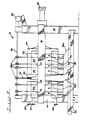
- Fig. 2 is a schematic side view of a dehydrator according to the invention;
- Figs. 3 and 4 are perspective views of an active press plate and a passive press plate, respectively, of the dehydrator of Fig. 2;
- Fig. 5 is a somewhat enlarged fragmentary view in cross section of the dehydrator of Fig. 2 showing adjacent active and passive plates; and
- Fig. 6 is a greatly enlarged fragmentary view in cross section of the active plate of Fig. 3.
- Referring to the drawings, the arrangement and construction shown in Fig. 2 is substantially conventional. The dehydrator comprises a
filter press 12, which includes afront frame 14, arear frame 16 and a pair ofhorizontal rails 18 fixed to the front and rear frames. Therails 18 support a front endpassive press plate 19 fixed to theframe 14, a number of alternating active andpassive press plates passive press plate 23, and arear end plate 24 which may be fixed to theframe 16. Theplates rails 18 by adrive 26. - The
frames horizontal shaft 28 at the top, which can be rotated by adrive 30 mounted on therear frame 16. From theshaft 28 are suspended pairs offilter cloths 32, which can be lowered and raised by rotating theshaft 28. Each pair ofcloths 32 is interposed betweenadjacent press plates cloths 32 are formed with aligned holes, each aligned with awasher 34 and opening downwardly (Fig. 5). - The frames also support a pair of
horizontal bus bars 36 connected to the positive and negative poles, respectively, of a DC power source (not shown). One ofbars 36 is connected throughcables 38 to theactive plates 20; theother bar 36 is connected throughother cables 38a to thepassive plates - With reference to Figs. 3, 5 and 6, each
active plate 20 has a generallyrectangular frame 40 which may be made of polypropylene. Theframe 40 has a wide recess 42 (Figs. 5 and 6) on each side and a shallower peripheral seat 44 around the recess. Therecess 42 is lined with apress diaphragm 46 which may be made of natural rubber, neoprene rubber or other electrically insulating flexible material. - The
diaphragm 46 has acentral portion 48, athin portion 50 of substantially the same width around the center portion and aperipheral margin 52, which is fixed to the seat 44. Themargin 52 has grooves 54 (Fig. 3) formed across its outer surface. - The
frame 40 hashorizontal passages center slurry passage 56 is aligned with ahole 62 formed through eachdiaphragm 46. Two of the threedrain passages 58 communicate throughpaths 63 with thediaphragm margin grooves 54. Theupper air passage 60 opens through apath 64 out of theframe 40 and upon the inner side ofdiaphragm 46. - The
central diaphragm portion 48 has a large number ofouter projections 66 of the same height, and is reinforced by acore plate 68 embedded in it. Thecore plates 68 on both sides are electrically connected to the associatedcable 38 each through abolt 69 and awire 71. Theseplates 68 may be made of iron, titanium, aluminum or other relatively electrically conductive metal. - Each
metal plate 68 supports a number of elongated horizontal and verticalelectric conductors 70, which are exposed through (or from) thediaphragm 46 and substantially flush with theprojections 66. Theconductors 70 may be made of stainless steel, copper, aluminum, titanium or carbon. - Each
conductor 70 is fixed to themetal plate 68 by a flush head screw 72 (Fig. 6) of stainless steel with electrically conductive adhesive coated between them. The gaps between theconductor 70 anddiaphragm 46 are sealed by calkingmaterial 73. - The
metal plate 68 is thus surrounded by the insulating anticorrosive material, except where theconductors 70 extend. This completely prevents theplate 68 from corroding with acids or alkalies produced on the electrodes during electrolytic reaction. - The outer surface of
conductor 70 is lined withcarbonic material 74 fixed by electrically conductive adhesive. Thismaterial 74 may be a carbon plate having carbon fibers bound by carbon, a graphite sheet or glassy carbon. - Four divided, generally
rectangular electrode plates 76, one of which is shown in Fig. 3, are each formed with a number of peripheral outer recessedseats 77 each having a hole through it. Theelectrodes 76 are fixed to theconductors 70 by plastic split snaps 78 resiliently snapping though theseats 77 andliners 74 into theconductors 70. The head of eachsnap 78 does not project from theseat 77. - To the bottom of
seat 77 is baked or adhered athin sheet 79 of polyvinyl chloride or other electrically insulating material in tight contact with the head ofsnap 78. Thesheet 79 insulates the upper surface of the thin bottom wall ofelectrode seat 77. - The
electrodes 76 can be easily removed by cutting thesnaps 78 by a nipper or the like. This snapping attachment permits quick replacement of damaged electrodes. - The plastic snaps 78 and insulating
sheets 79 do not conduct electricity, and are not dissolved by electrolytic reaction. This prevents electrolytic dissolusion of the thin bottom walls ofelectrode seats 77, and consequently secures the attachment ofelectrodes 76 to theconductors 70. - Each
conductor 70 extends adjacent and in parallel with one of the four sides of eachelectrode 76. This arrangement reduces the bending forces exerted on theelectrodes 76 via theconductors 70, and equalizes the electric application to the electrodes. - The
electrodes 76 are supported by thediaphragm projections 66 as well as theconductors 70. Eachelectrode plate 76 has three right angle corners supported by thewider projections 66 not to be broken by the motion ofdiaphragm 46. Theelectrode 76 has a large number ofsmall holes 80 formed through it spaced from theprojections 66 andconductors 70. - With reference to Figs. 4 and 5, each
passive press plate active plate 20, but has no diaphragm. - The passive plate has a
frame 140 formed with awide recess 142 on each side corresponding to the active plate recesses 42. Theframe 140 has aslurry passage 156, drainpassages 158 and anair passage 160 formed through it in respective alignment with theactive plate passages drain passages 158 opens into therecesses 142 throughpaths 163. - To the bottom of each
recess 142 of each intermediatepassive plate 22 are fixed twohorizontal conductors 168, which are connected to the associatedelectric cable 38a. Theseconductors 168 support a number ofvertical conductors 170 fixed to their outer surfaces byflush screws 172. The outer surfaces ofvertical conductors 170 may be lined with carbonic material similar to the liners 74 (Fig. 6). - The
vertical conductors 170 support four (one shown in Fig. 4)electrode plates 176, which are substantially the same as theelectrodes 76 and fixed to the conductors byplastic snaps 178 similarly to theelectrodes 76. Eachelectrode 176 has a number of small holes 180 through it. - Such electrodes and conductors as 176, 168 and 170 are also provided on one side of each end
passive plate active plate 20. - Back to Fig. 2, the
front frame 14 is provided with aslurry inlet 82,drain outlets 84 and an air inlet (not shown) in respective alignment with theslurry passages drain passages air passage 160. - In the first step of operation, the
drive 26 forces theend plate 24 to compress thepress plates frame 14. This makes the adjacent press plates form sealed filter spaces between thewide recesses inlet 82,passages washers 34 to collect between and swell thecloths 32 in the sealed spaces. This forces an amount of filtrate from the slurry to permeate through thecloths 32 and drain through the electrode holes 80 and 180,diaphragm corner grooves 54,paths passages outlets 84. - In the second step, compressed air is fed through the
passages paths 64 to swell thediaphragms 46 compressing cakes which have resulted from the slurry, in the same manner as shown in Fig. 1b. In a later stage of this step, DC voltage is applied between theelectrodes - In the final step, the press plates are separated from each other, in the same manner as shown in Fig. 1c, so that the cakes can be removed.
- Thus, the arrangement according to the present invention enables the diaphragms supporting the electrodes to effect more equal compression of the slurry. The individual divided electrodes bear the divided pressures more evenly so that they are less liable to break. This also simplifies, shortens and equalizes the electrical pathways to the electrodes.
Claims (8)
first and second electrically insulating press plates (20,22) supported in parallel and adapted to be moved into face-to-face abutment, each press plate having in its face a recess (42,142) which registers with the recess in the face of the other plate to form a closed chamber for dehydrating feed liquid when the plates are in abutment;
an electrically insulating diaphragm (46) attached at its margin to the first press plate (20) to line the recess and adapted to be displaced towards the second plate (22) under the influence of a compressed fluid forced between the diaphragm and the first plate;
a metal core plate (68) embedded within the diaphragm to reinforce the diaphragm except at its margin, and connected (38) to one pole of an electric DC power source;
electric conductors (70) attached in electric connection to the core plate and projecting through the diaphragm towards the second press plate;
a plurality of divided flush carbon electrode plates (76) electrically connected to the conductors over the diaphragm and core plate; and
an electrode plate (176) supported in the recess (142) of the second press plate (22) in parallel with the divided electrode plates, and connected (38) to the other pole of the power source.
an electrically insulating frame having in its face a recess (42) for registering with the recess in the face of another press plate to form a closed chamber for dehydrating feed liquid when the plates are in face-to-face abutment;
an electrically insulating diaphragm (46) fixed at its margin to the frame to line the recess and adapted to be displaced under the influence of a compressed fluid forced between the diaphragm and the frame;
a metal core plate (68) embedded within the diaphragm to reinforce the diaphragm except at its margin, and adapted to be connected (38) to one pole of an electric DC power source;
electric conductors (70) attached in electric connection to the core plate and projecting through the diaphragm; and
a plurality of divided flush carbon electrode plates (76) electrically connected to the conductors over the diaphragm and core plate.
Applications Claiming Priority (4)
| Application Number | Priority Date | Filing Date | Title |
|---|---|---|---|
| JP1988169368U JPH055924Y2 (en) | 1988-12-28 | 1988-12-28 | |
| JP169368/88U | 1988-12-28 | ||
| JP169369/88U | 1988-12-28 | ||
| JP16936988U JPH0444174Y2 (en) | 1988-12-28 | 1988-12-28 |
Publications (3)
| Publication Number | Publication Date |
|---|---|
| EP0384081A2 true EP0384081A2 (en) | 1990-08-29 |
| EP0384081A3 EP0384081A3 (en) | 1991-02-27 |
| EP0384081B1 EP0384081B1 (en) | 1993-11-03 |
Family
ID=26492729
Family Applications (1)
| Application Number | Title | Priority Date | Filing Date |
|---|---|---|---|
| EP89313206A Expired - Lifetime EP0384081B1 (en) | 1988-12-28 | 1989-12-18 | Compressive and electroosmotic dehydrator |
Country Status (3)
| Country | Link |
|---|---|
| US (1) | US5034111A (en) |
| EP (1) | EP0384081B1 (en) |
| DE (1) | DE68910504T2 (en) |
Cited By (7)
| Publication number | Priority date | Publication date | Assignee | Title |
|---|---|---|---|---|
| EP0520698A3 (en) * | 1991-06-26 | 1993-03-17 | Shinko Pantec Co., Ltd. | Method of electroosmotically dehydrating sludge |
| FR2805199A1 (en) * | 2000-02-22 | 2001-08-24 | Gradient Ass | METHOD FOR EXTRACTING LIQUID FROM A CELLULAR MATERIAL, AND DEVICES FOR IMPLEMENTING SAID METHOD |
| CN101249327B (en) * | 2007-05-21 | 2011-04-20 | 杭州兴源过滤科技股份有限公司 | Damp cavity sealed type jogged dissepiment strainer plate and sealing method thereof |
| FR3042186A1 (en) * | 2015-10-12 | 2017-04-14 | Veolia Water Solutions & Tech | SLUDGE DEHYDRATION DEVICE |
| WO2019008037A1 (en) * | 2017-07-05 | 2019-01-10 | Jvk Filtration Systems Gmbh | ARRANGEMENT OF A FILTER PLATE AND AN ASSEMBLY PART |
| FR3069451A1 (en) * | 2017-07-25 | 2019-02-01 | Ste De Fabrication Et Ateliers Lucien Choquenet | IMPROVED FILTRATION METHOD AND PRESS FILTER |
| CN110282857B (en) * | 2019-06-17 | 2023-12-15 | 河南工程学院 | Spiral propulsion combined biomass electroosmosis sludge dewatering device and method |
Families Citing this family (8)
| Publication number | Priority date | Publication date | Assignee | Title |
|---|---|---|---|---|
| US6030538A (en) * | 1995-11-02 | 2000-02-29 | Held; Jeffery S. | Method and apparatus for dewatering previously-dewatered municipal waste-water sludges using high electrical voltages |
| US7507341B2 (en) * | 1999-01-13 | 2009-03-24 | Opencel Llc | Method of and apparatus for converting biological materials into energy resources |
| US5695650A (en) * | 1995-11-02 | 1997-12-09 | Held; Jeffery S. | Method for dewatering previously-dewatered municipal waste-water sludges using high electrical voltage |
| US5893979A (en) * | 1995-11-02 | 1999-04-13 | Held; Jeffery S. | Method for dewatering previously-dewatered municipal waste-water sludges using high electrical voltage |
| US6709594B2 (en) * | 1995-11-02 | 2004-03-23 | Dh20, L.L.C. | Method for treating waste-activated sludge using electroporation |
| DE10007438C1 (en) * | 2000-02-18 | 2001-06-07 | Hoesch & Soehne Eberhard | Filter press for filtering suspensions has electrodes for producing an electrical field formed from the pressing fluid chamber filled in the filtration operation with an electrically conducting pressing fluid |
| US7572369B2 (en) * | 2007-02-16 | 2009-08-11 | Opencel Llc | System for supporting denitrification |
| FR3033164B1 (en) * | 2015-02-26 | 2020-01-31 | Veolia Water Solutions & Technologies Support | SLUDGE DEHYDRATION PROCESS |
Family Cites Families (8)
| Publication number | Priority date | Publication date | Assignee | Title |
|---|---|---|---|---|
| DE347598C (en) * | 1920-02-06 | 1922-01-23 | Elektro Osmose Akt Ges Graf Sc | Method and device for electroosmotic drainage |
| US3773640A (en) * | 1972-02-28 | 1973-11-20 | Mc Graw Edison Co | Method for treating wet process ceramic bodies |
| EP0022072B1 (en) * | 1979-06-05 | 1983-07-27 | Battelle Memorial Institute | Method and apparatus for concentrating aqueous sludge by electroosmosis |
| JPS6225811A (en) * | 1985-07-25 | 1987-02-03 | 松下電工株式会社 | Wiring apparatus |
| JPS6257622A (en) * | 1985-09-05 | 1987-03-13 | Shinko Fuaudoraa Kk | Electroosmotic dehydrator |
| JPS6257623A (en) * | 1985-09-06 | 1987-03-13 | Shinko Fuaudoraa Kk | Electroosmotic dehydrator |
| JPH0679645B2 (en) * | 1985-11-25 | 1994-10-12 | 神鋼パンテック株式会社 | Peeling method of dehydrated sludge in electroosmosis dehydrator |
| JPS62125810A (en) * | 1985-11-25 | 1987-06-08 | Shinko Fuaudoraa Kk | Method for electroosmosis dehydration |
-
1989
- 1989-12-18 EP EP89313206A patent/EP0384081B1/en not_active Expired - Lifetime
- 1989-12-18 DE DE89313206T patent/DE68910504T2/en not_active Expired - Fee Related
- 1989-12-27 US US07/457,379 patent/US5034111A/en not_active Expired - Lifetime
Cited By (15)
| Publication number | Priority date | Publication date | Assignee | Title |
|---|---|---|---|---|
| EP0520698A3 (en) * | 1991-06-26 | 1993-03-17 | Shinko Pantec Co., Ltd. | Method of electroosmotically dehydrating sludge |
| US5279718A (en) * | 1991-06-26 | 1994-01-18 | Shinko Pantec Co., Ltd. | Method of electroosmotically dehydrating sludge |
| FR2805199A1 (en) * | 2000-02-22 | 2001-08-24 | Gradient Ass | METHOD FOR EXTRACTING LIQUID FROM A CELLULAR MATERIAL, AND DEVICES FOR IMPLEMENTING SAID METHOD |
| WO2001062482A1 (en) * | 2000-02-22 | 2001-08-30 | Association Gradient | Method for extracting liquid from a cellular material and devices therefor |
| CN101249327B (en) * | 2007-05-21 | 2011-04-20 | 杭州兴源过滤科技股份有限公司 | Damp cavity sealed type jogged dissepiment strainer plate and sealing method thereof |
| WO2017064412A1 (en) * | 2015-10-12 | 2017-04-20 | Veolia Water Solutions & Technologies Support | Device for dehydration of sludges |
| FR3042186A1 (en) * | 2015-10-12 | 2017-04-14 | Veolia Water Solutions & Tech | SLUDGE DEHYDRATION DEVICE |
| US11021385B2 (en) | 2015-10-12 | 2021-06-01 | Veolia Water Solutions & Technologies Support | Sludge dewatering device |
| WO2019008037A1 (en) * | 2017-07-05 | 2019-01-10 | Jvk Filtration Systems Gmbh | ARRANGEMENT OF A FILTER PLATE AND AN ASSEMBLY PART |
| CN110869101A (en) * | 2017-07-05 | 2020-03-06 | Jvk过滤系统有限公司 | Unit including filter plate and accessories |
| EA038616B1 (en) * | 2017-07-05 | 2021-09-23 | ДжВК ФИЛЬТРЕЙШН СИСТЕМС ГМБХ | Assembly comprising a filter plate and an attachment part |
| CN110869101B (en) * | 2017-07-05 | 2022-06-07 | Jvk过滤系统有限公司 | Device comprising a filter plate and an attachment |
| US12370472B2 (en) | 2017-07-05 | 2025-07-29 | Jvk Filtration Systems Gmbh | Assembly comprising a filter plate and an attachment part |
| FR3069451A1 (en) * | 2017-07-25 | 2019-02-01 | Ste De Fabrication Et Ateliers Lucien Choquenet | IMPROVED FILTRATION METHOD AND PRESS FILTER |
| CN110282857B (en) * | 2019-06-17 | 2023-12-15 | 河南工程学院 | Spiral propulsion combined biomass electroosmosis sludge dewatering device and method |
Also Published As
| Publication number | Publication date |
|---|---|
| DE68910504D1 (en) | 1993-12-09 |
| US5034111A (en) | 1991-07-23 |
| EP0384081B1 (en) | 1993-11-03 |
| DE68910504T2 (en) | 1994-02-24 |
| EP0384081A3 (en) | 1991-02-27 |
Similar Documents
| Publication | Publication Date | Title |
|---|---|---|
| EP0384081B1 (en) | Compressive and electroosmotic dehydrator | |
| US4425214A (en) | Novel bipolar electrolyzer | |
| WO1998029912A3 (en) | Electrochemical cells and electrochemical systems | |
| EP1114486B1 (en) | Membrane-separated, bipolar multicell electrochemical reactor | |
| KR100931754B1 (en) | Electrolytic cells, especially for the production of electrochemical chlorine | |
| US3236760A (en) | Cells for the production of chlorine from hydrochloric acid | |
| EP0055931B1 (en) | Gasket lubricating means | |
| AU550325B2 (en) | Filter press electrolytic cell | |
| US20110272277A1 (en) | Electrolytic cell and related methods of making and use | |
| EP0132079A1 (en) | A method of assembling a filter press type electrolytic cell | |
| US2858263A (en) | Diaphragm type electrolytic cell | |
| AU561366B2 (en) | Filter press membrane cell | |
| JPH0919628A (en) | End casing for electrodialysis machine, electrodialysis machine with such casing, and use of this electrodialysis machine | |
| CA2125756A1 (en) | Filter press electrolyzer | |
| EP0266106B1 (en) | Method of assembling filter press type structure | |
| US4257866A (en) | Electrolyzer cell | |
| JPS6326391A (en) | Filter press type electrolytic cell | |
| JPS6257622A (en) | Electroosmotic dehydrator | |
| JPH08158084A (en) | Electrolytic cell | |
| JPH02111410A (en) | Electrode composite diaphragm of electroosmotic press dehydrator | |
| JPH055924Y2 (en) | ||
| CN223118218U (en) | Sealing structure for EDI membrane stack | |
| CN220802670U (en) | Electrodialysis membrane stack assembly | |
| WO2009151685A1 (en) | Electrolytic cell and related methods of making and use | |
| CN218770352U (en) | Electric energy meter termination |
Legal Events
| Date | Code | Title | Description |
|---|---|---|---|
| PUAI | Public reference made under article 153(3) epc to a published international application that has entered the european phase |
Free format text: ORIGINAL CODE: 0009012 |
|
| AK | Designated contracting states |
Kind code of ref document: A2 Designated state(s): CH DE FR GB LI NL SE |
|
| PUAL | Search report despatched |
Free format text: ORIGINAL CODE: 0009013 |
|
| AK | Designated contracting states |
Kind code of ref document: A3 Designated state(s): CH DE FR GB LI NL SE |
|
| 17P | Request for examination filed |
Effective date: 19910805 |
|
| 17Q | First examination report despatched |
Effective date: 19920731 |
|
| GRAA | (expected) grant |
Free format text: ORIGINAL CODE: 0009210 |
|
| AK | Designated contracting states |
Kind code of ref document: B1 Designated state(s): CH DE FR GB LI NL SE |
|
| REF | Corresponds to: |
Ref document number: 68910504 Country of ref document: DE Date of ref document: 19931209 |
|
| ET | Fr: translation filed | ||
| PLBE | No opposition filed within time limit |
Free format text: ORIGINAL CODE: 0009261 |
|
| STAA | Information on the status of an ep patent application or granted ep patent |
Free format text: STATUS: NO OPPOSITION FILED WITHIN TIME LIMIT |
|
| 26N | No opposition filed | ||
| EAL | Se: european patent in force in sweden |
Ref document number: 89313206.8 |
|
| REG | Reference to a national code |
Ref country code: GB Ref legal event code: IF02 |
|
| PGFP | Annual fee paid to national office [announced via postgrant information from national office to epo] |
Ref country code: NL Payment date: 20041205 Year of fee payment: 16 |
|
| PGFP | Annual fee paid to national office [announced via postgrant information from national office to epo] |
Ref country code: SE Payment date: 20041206 Year of fee payment: 16 |
|
| PGFP | Annual fee paid to national office [announced via postgrant information from national office to epo] |
Ref country code: FR Payment date: 20041208 Year of fee payment: 16 |
|
| PGFP | Annual fee paid to national office [announced via postgrant information from national office to epo] |
Ref country code: GB Payment date: 20041215 Year of fee payment: 16 Ref country code: CH Payment date: 20041215 Year of fee payment: 16 |
|
| PGFP | Annual fee paid to national office [announced via postgrant information from national office to epo] |
Ref country code: DE Payment date: 20041216 Year of fee payment: 16 |
|
| PG25 | Lapsed in a contracting state [announced via postgrant information from national office to epo] |
Ref country code: GB Free format text: LAPSE BECAUSE OF NON-PAYMENT OF DUE FEES Effective date: 20051218 |
|
| PG25 | Lapsed in a contracting state [announced via postgrant information from national office to epo] |
Ref country code: SE Free format text: LAPSE BECAUSE OF NON-PAYMENT OF DUE FEES Effective date: 20051219 |
|
| PG25 | Lapsed in a contracting state [announced via postgrant information from national office to epo] |
Ref country code: LI Free format text: LAPSE BECAUSE OF NON-PAYMENT OF DUE FEES Effective date: 20051231 Ref country code: CH Free format text: LAPSE BECAUSE OF NON-PAYMENT OF DUE FEES Effective date: 20051231 |
|
| PG25 | Lapsed in a contracting state [announced via postgrant information from national office to epo] |
Ref country code: NL Free format text: LAPSE BECAUSE OF NON-PAYMENT OF DUE FEES Effective date: 20060701 Ref country code: DE Free format text: LAPSE BECAUSE OF NON-PAYMENT OF DUE FEES Effective date: 20060701 |
|
| REG | Reference to a national code |
Ref country code: CH Ref legal event code: PL |
|
| EUG | Se: european patent has lapsed | ||
| GBPC | Gb: european patent ceased through non-payment of renewal fee |
Effective date: 20051218 |
|
| PG25 | Lapsed in a contracting state [announced via postgrant information from national office to epo] |
Ref country code: FR Free format text: LAPSE BECAUSE OF NON-PAYMENT OF DUE FEES Effective date: 20060831 |
|
| NLV4 | Nl: lapsed or anulled due to non-payment of the annual fee |
Effective date: 20060701 |
|
| REG | Reference to a national code |
Ref country code: FR Ref legal event code: ST Effective date: 20060831 |