EP0384042A2 - Magneto-strictive torque sensor - Google Patents
Magneto-strictive torque sensor Download PDFInfo
- Publication number
- EP0384042A2 EP0384042A2 EP89201428A EP89201428A EP0384042A2 EP 0384042 A2 EP0384042 A2 EP 0384042A2 EP 89201428 A EP89201428 A EP 89201428A EP 89201428 A EP89201428 A EP 89201428A EP 0384042 A2 EP0384042 A2 EP 0384042A2
- Authority
- EP
- European Patent Office
- Prior art keywords
- magneto
- rotary shaft
- torque sensor
- torque
- fine dents
- Prior art date
- Legal status (The legal status is an assumption and is not a legal conclusion. Google has not performed a legal analysis and makes no representation as to the accuracy of the status listed.)
- Granted
Links
- 230000005291 magnetic effect Effects 0.000 claims abstract description 61
- 230000035699 permeability Effects 0.000 claims abstract description 19
- 230000008859 change Effects 0.000 claims abstract description 13
- 238000005096 rolling process Methods 0.000 claims description 8
- 238000005480 shot peening Methods 0.000 claims description 5
- 230000005611 electricity Effects 0.000 claims description 4
- 238000004049 embossing Methods 0.000 claims 1
- 238000001514 detection method Methods 0.000 abstract description 44
- 230000005415 magnetization Effects 0.000 abstract description 40
- 238000000034 method Methods 0.000 abstract description 32
- 230000008569 process Effects 0.000 abstract description 29
- 230000035945 sensitivity Effects 0.000 abstract description 19
- 230000005381 magnetic domain Effects 0.000 abstract description 11
- 230000002829 reductive effect Effects 0.000 abstract description 11
- 238000006073 displacement reaction Methods 0.000 abstract description 10
- 230000002441 reversible effect Effects 0.000 abstract description 10
- 239000002344 surface layer Substances 0.000 abstract description 6
- 230000035882 stress Effects 0.000 description 17
- 230000005284 excitation Effects 0.000 description 12
- 239000000463 material Substances 0.000 description 12
- PXHVJJICTQNCMI-UHFFFAOYSA-N nickel Substances [Ni] PXHVJJICTQNCMI-UHFFFAOYSA-N 0.000 description 8
- 230000015572 biosynthetic process Effects 0.000 description 7
- 230000000694 effects Effects 0.000 description 7
- 238000012360 testing method Methods 0.000 description 7
- 229910052759 nickel Inorganic materials 0.000 description 6
- XEEYBQQBJWHFJM-UHFFFAOYSA-N Iron Chemical group [Fe] XEEYBQQBJWHFJM-UHFFFAOYSA-N 0.000 description 5
- 229910000831 Steel Inorganic materials 0.000 description 5
- 238000010438 heat treatment Methods 0.000 description 5
- 238000005259 measurement Methods 0.000 description 5
- 239000010959 steel Substances 0.000 description 5
- 238000010276 construction Methods 0.000 description 4
- 229910001240 Maraging steel Inorganic materials 0.000 description 3
- 230000000052 comparative effect Effects 0.000 description 3
- 239000003302 ferromagnetic material Substances 0.000 description 3
- 230000002427 irreversible effect Effects 0.000 description 3
- 238000003754 machining Methods 0.000 description 3
- 238000012423 maintenance Methods 0.000 description 3
- 238000010791 quenching Methods 0.000 description 3
- 230000000171 quenching effect Effects 0.000 description 3
- 229910000851 Alloy steel Inorganic materials 0.000 description 2
- 229910001182 Mo alloy Inorganic materials 0.000 description 2
- 230000032683 aging Effects 0.000 description 2
- 230000003247 decreasing effect Effects 0.000 description 2
- 230000007547 defect Effects 0.000 description 2
- 230000005294 ferromagnetic effect Effects 0.000 description 2
- 230000006872 improvement Effects 0.000 description 2
- 229910052750 molybdenum Inorganic materials 0.000 description 2
- 239000011733 molybdenum Substances 0.000 description 2
- 230000002269 spontaneous effect Effects 0.000 description 2
- 238000004804 winding Methods 0.000 description 2
- 229910000975 Carbon steel Inorganic materials 0.000 description 1
- VYZAMTAEIAYCRO-UHFFFAOYSA-N Chromium Chemical compound [Cr] VYZAMTAEIAYCRO-UHFFFAOYSA-N 0.000 description 1
- 229910001208 Crucible steel Inorganic materials 0.000 description 1
- 229910000805 Pig iron Inorganic materials 0.000 description 1
- 230000002411 adverse Effects 0.000 description 1
- 239000010962 carbon steel Substances 0.000 description 1
- 230000006835 compression Effects 0.000 description 1
- 238000007906 compression Methods 0.000 description 1
- 239000012141 concentrate Substances 0.000 description 1
- 238000000280 densification Methods 0.000 description 1
- 230000003292 diminished effect Effects 0.000 description 1
- 238000009826 distribution Methods 0.000 description 1
- 230000002349 favourable effect Effects 0.000 description 1
- 239000010419 fine particle Substances 0.000 description 1
- 230000004907 flux Effects 0.000 description 1
- 239000012535 impurity Substances 0.000 description 1
- 230000006698 induction Effects 0.000 description 1
- 239000000696 magnetic material Substances 0.000 description 1
- 229910052751 metal Inorganic materials 0.000 description 1
- 239000002184 metal Substances 0.000 description 1
- 230000002093 peripheral effect Effects 0.000 description 1
- 238000003825 pressing Methods 0.000 description 1
- 238000012552 review Methods 0.000 description 1
- 239000007779 soft material Substances 0.000 description 1
- 239000007921 spray Substances 0.000 description 1
- 238000005482 strain hardening Methods 0.000 description 1
- 238000005496 tempering Methods 0.000 description 1
- 238000003466 welding Methods 0.000 description 1
Images


Classifications
-
- G—PHYSICS
- G01—MEASURING; TESTING
- G01L—MEASURING FORCE, STRESS, TORQUE, WORK, MECHANICAL POWER, MECHANICAL EFFICIENCY, OR FLUID PRESSURE
- G01L3/00—Measuring torque, work, mechanical power, or mechanical efficiency, in general
- G01L3/02—Rotary-transmission dynamometers
- G01L3/04—Rotary-transmission dynamometers wherein the torque-transmitting element comprises a torsionally-flexible shaft
- G01L3/10—Rotary-transmission dynamometers wherein the torque-transmitting element comprises a torsionally-flexible shaft involving electric or magnetic means for indicating
- G01L3/101—Rotary-transmission dynamometers wherein the torque-transmitting element comprises a torsionally-flexible shaft involving electric or magnetic means for indicating involving magnetic or electromagnetic means
- G01L3/102—Rotary-transmission dynamometers wherein the torque-transmitting element comprises a torsionally-flexible shaft involving electric or magnetic means for indicating involving magnetic or electromagnetic means involving magnetostrictive means
- G01L3/103—Details about the magnetic material used
-
- G—PHYSICS
- G01—MEASURING; TESTING
- G01L—MEASURING FORCE, STRESS, TORQUE, WORK, MECHANICAL POWER, MECHANICAL EFFICIENCY, OR FLUID PRESSURE
- G01L3/00—Measuring torque, work, mechanical power, or mechanical efficiency, in general
- G01L3/02—Rotary-transmission dynamometers
- G01L3/04—Rotary-transmission dynamometers wherein the torque-transmitting element comprises a torsionally-flexible shaft
- G01L3/10—Rotary-transmission dynamometers wherein the torque-transmitting element comprises a torsionally-flexible shaft involving electric or magnetic means for indicating
- G01L3/101—Rotary-transmission dynamometers wherein the torque-transmitting element comprises a torsionally-flexible shaft involving electric or magnetic means for indicating involving magnetic or electromagnetic means
- G01L3/105—Rotary-transmission dynamometers wherein the torque-transmitting element comprises a torsionally-flexible shaft involving electric or magnetic means for indicating involving magnetic or electromagnetic means involving inductive means
-
- H—ELECTRICITY
- H10—SEMICONDUCTOR DEVICES; ELECTRIC SOLID-STATE DEVICES NOT OTHERWISE PROVIDED FOR
- H10N—ELECTRIC SOLID-STATE DEVICES NOT OTHERWISE PROVIDED FOR
- H10N35/00—Magnetostrictive devices
- H10N35/101—Magnetostrictive devices with mechanical input and electrical output, e.g. generators, sensors
-
- Y—GENERAL TAGGING OF NEW TECHNOLOGICAL DEVELOPMENTS; GENERAL TAGGING OF CROSS-SECTIONAL TECHNOLOGIES SPANNING OVER SEVERAL SECTIONS OF THE IPC; TECHNICAL SUBJECTS COVERED BY FORMER USPC CROSS-REFERENCE ART COLLECTIONS [XRACs] AND DIGESTS
- Y10—TECHNICAL SUBJECTS COVERED BY FORMER USPC
- Y10S—TECHNICAL SUBJECTS COVERED BY FORMER USPC CROSS-REFERENCE ART COLLECTIONS [XRACs] AND DIGESTS
- Y10S73/00—Measuring and testing
- Y10S73/02—Magnetostrictive
Definitions
- the present invention relates to a magneto-strictive torque sensor for contactlessly detecting torque applied to a rotary shaft on the basis of a change in the magnetic permeability of the surface of the shaft.
- magneto-stricitive torque sensors are widely used in which an alternating field is applied to the surface of the shaft so that a change in the magnetic permeability of the shaft surface which arises from application of torque to the rotary shaft is detected in terms of quantity of electricity.
- magneto-strictive sensor is of the magnetic head system in which a coil winding (a magnetic head) having an open magnetic circuit type iron core, such as U-shaped iron core, is disposed adjacent the shaft to serve as exciting and detecting means, whereby a change in the magnetic permeability of the shaft surface in the direction of principal stress (a direction having an angular inclination of ⁇ 45 deg. relative to the axial direction of the shaft) which arises from application of torque to the shaft is detected ("Magnetic Measurement of Torque in a Rotating Shaft", The Review of Scientific Instruments, Vol. 25, No. 6, June 1954).
- Another known type is of the solenoid coil system such that uniaxial magnetic anisotropy in which a direction having an angular inclination relative to the axial direction of the rotary shaft is an axis of easy magnetization is imparted to the surface of the rotary shaft and, in proximity to the shaft portion to which the magnetic anisotropy is imparted, an exciting solenoid coil (exciting coil) and a solenoid coil for detecting changes in magnetic permeability (detecting coil) are arranged around the shaft so that an axial change in the magnetic permeability which is caused by torque application is detected ("A New Torque transducer using Stress Sensitive Amorphous Ribbons", IEEE Trans. on Mag., MAG-18, No. 6, 1769 - 9, 1982).
- Changes in the spontaneous magnetization of a ferromagnetic material which are caused by external magnetic field and/or stress acting on the rotary shaft include the process of magnetization due to magnetic domain wall displacement and the process of magnetization due to rotational magnetization which follows the first mentioned domain wall displacement.
- the process of magnetization due to rotational magnetization is mainly reversible.
- the process of magnetization due to magnetic domain wall displacement includes the process of reversible magnetization and the process of irreversible magnetization. Unless the external magnetic field and/or active stress is extremely small or unless it is noticeably large, the process of magnetization due to magnetic domain wall displacement is irreversible.
- magnetic field applied to the surface of the rotary shaft is usually faint (generally not more than 10 Oe) and, therefore, the process of magnetization on the surface of a conventional rotary shaft made of a magnetically soft material of high-strength (coercive force Hc: about 10 - 20 Oe) is largely of irreversible magnetization due to magnetic domain wall displacement. As such, hysteresis cannot be avoided in the process of magnetization. The hysteresis in the process of magnetization appears as hysteresis in the detection characteristics of the torque sensor, thus adversely affecting the accuracy of torque detection.
- the present invention provides a magneto-strictive torque sensor of the type in which an exciting magnetic field is applied to a megneto-anisotropic zone formed on the surface of a predetermined region of a rotary shaft so that a change in the magnetic permeability of the magneto-anisotropic zone which arises from torque being applied to the rotary shaft is contactlessly detected by magnetic detecting means in terms of quantity of electricity, characterized in that fine dents and retainer areas for retaining residual compressive stress due to the fine dents are formed on the surface of the rotary shaft over a predetermined region including the magneto-anisotropic zone so that they are substantially uniformly distributed over the region.
- Fine dents on the surface of the rotary shaft are formed by shot peening, a process in which rigid spherical materials, such as pig iron and cast steel, of fine particle size are sprayed onto the shaft surface by utilizing compressed air or centrifugal force, or by rolling or knurling, a process in which a roll forming tool having a multiplicity of fine protrusions on the surface thereof is pressed against the shaft surface (and where required, such pressing is repeated.)
- the surface of the rotary shaft in the region in which a multiplicity of fine dents are scatteringly formed has a metallic texture compressed and densified by dent forming.
- the surface layer of the shaft is rendered rigid as a result of work hardening due to the process of dent forming.
- Such densification by compression and hardening of the surface layer are also effective in increasing the fatigue resistance and intergranular slip resistance of the surface layer and result in reduced hysteresis in torque detection characteristics.
- Fine dent forming on the predetermined region of the rotary shaft surface may be carried out after the required tempering steps, such as heat treatment and carburization, with respect to the rotary shaft, or where uniaxial magnetic anisotropy is to be given to the surface of the rotary shaft, such dent forming may be carried out after the required step for giving such magnetic anisotropy is effected.
- a rolling tool die having a multiplicity of protrusions scatteringly formed on its face is employed for the purpose, whereby spiral grooves and fine dents can be simultaneously formed.
- Fine dents formed on the shaft surface may not necessarily be of strictly regular arrangement; they may be acceptable if they are substantially uniformly distributed.
- the diameter of each of the dents may be generally of the order of 0.1 to 1 mm.
- the coverage of the dents on the surface area is preferably not less than 70 %, more preferably not less than 90 %.
- a depth of not more than 0.1 mm is sufficient for the fine dents; there is no particular need for any greater depth.
- the depth (skin depth) of a passage within the shaft for a magnetic flux applied to the shaft surface by the frequency (about 10 kHz to 50 kHz) of a normally used exciting current is about 0.1 mm or less, it is well possible to provide the skin of the shaft, as a magnetic path, with above mentioned effect of fine-dent formation by forming fine dents of about 0.1 mm or less in depth.
- the material of the rotary shaft to which the invention is applied is not particularly limited.
- Materials useful for the purpose include various different materials, such as carbon steel, chrome alloy steel, nickel-chrome alloy steel, chrome-molybdenum alloy steel, nickel-chrome-molybdenum alloy steel, and maraging steel.
- the system for magnetic excitation of the rotary shaft surface and detection of changes in magnetic permeability may be of a solenoid coil system using a solenoid coil concentrically wound along the outer periphery of the rotary shaft or may be of a magnetic head system using a magnetic head with a coil winding placed on a U-shaped iron core.
- any circuit configuration may be employed.
- spiral grooves are formed in the surface of the rotary shaft to provide uniaxial magnetic anisotropy in which the direction of the angular inclination of the spiral grooves constitutes an axis of easy magnetization.
- such uniaxial magnetic anisotropy may be provided by any other suitable method.
- a plurality of belt-like hardened sections which are angularly inclined relative to the axial direction are formed by laser quenching at a certain pitch in a circumferential direction, or belt-like carburized sections inclined angularly relative to the axial direction are formed at a certain pitch in a circumferential direction, to arrange for provision of uniaxial magnetic anisotropy through the formation of such inclined belt-like hardened sections or belt-like carburized sections.
- the torque sensor in the embodiment to be explained hereinafter has a differential-type construction in which two adjacent zones on the surface of the rotary shaft are provided with different uniaxial magnetic anisotropies which are equally angularly inclined relative to the axial direction but are inclined in reverse relation to each other so that changes in magnetic permeability in the respective zones are differentially sensed.
- such construction is not always required.
- an excitation/detection circuit which detects the magnitude of torque applied to the rotary shaft and the direction of torque application, positive or negative (forward or reverse), on the basis of a change in magnetic permeability in only one zone provided with uniaxial magnetic anisotropy.
- the arrangement described above have fine dents formed on the surface of the rotary shaft itself.
- the shaft is formed of a material having minor or non magneto-strictive effect
- a sleeve made of a ferro-magnetic metal having greater magneto-strictive effect is firmly fitted and fixed to the desired surface portion of the rotary shaft by welding, bonding, shrinkage fitting, cold fitting, or otherwise so that stress resulting from the torque applied to the rotary shaft is transmitted to the sleeve, whereby a change in the magnetic permeability of the sleeve is detected.
- the surface of the rotary shaft on which fine dents are formed when referred to as such, means not only the surface of the shaft itself, but also the surface of the sleeve as a magneto-strictive member fitted fixedly to the shaft.
- the hysteresis involved in the detection of torque of the rotary shaft is smaller and the detecting sensitivity is higher.
- highly accurate torque detection is possible and thus the reliability of torque detection in rotary drive system control is enhanced.
- the principle of the invention that by forming fine dents on the surface of a ferro-magnetic element the magnetic properties of the element are changed is applicable not only to torque detection with respect to rotary shafts, but also to maintenance of various structures and management of changes of material characteristics with time and age through utilization of magneto-strictive phenomena. For example, when carrying out load measurement and maintenance of buildings, bridges, etc., maintenance and preliminary testing of plant equipment and high-pressure tanks, and/or measurement of residual stress distribution in welded structures, improved measurement accuracy and improved measurement reliability can be obtained by arranging that fine dents are formed at spots required to be measured.
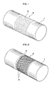
- FIG. 1 shows an embodiment in which a multiplicity of fine dents 2 are formed on the surface of a rotary shaft 1 so that they are distributed over a predetermined region A.
- FIG. 2 shows another embodiment in which a multiplicity of spiral grooves 3 are circumferentially formed in spaced relation and in parallel to one another and in which a multiplicity of fine dents 2 are scatteringly formed on the rotary shaft in the region in which the spiral grooves are formed and also in adjacent areas.
- the following rotary shafts (a) to (d) (all with a shaft diameter of 30 mm) are prepared, and they are all formed on their respective surfaces with same sprial grooves and fine dents as shown in FIG. 2.
- a solenoid coil type excitation/detection circuit as shown in FIG. 3 is arranged in conjunction with each of the rotary shaft to form a torque sensor. Torque detecting test was carried out with respect to each sensor.
- Excitation/detection circuits were individually arranged on the rotary shafts (a) to (d) to from torque sensors (a) to (d).
- FIG. 3 shows the disposition of each excitation/detection circuit in relation to the corresponding rotary shaft 1.
- FIG. 4 shows the arrangement of the excitation/detection circuit.
- the two areas (A), (A) having spiral grooves 3, 3 and fine dents 2 formed therein, on the surface of the shaft are each referred to as "magneto-strictive sections".
- numeral 6 designates a solenoid coil (exciting coil) for applying exciting field to the "magneto-strictive sections" (A), (A), and 8, 8 designate solenoid coils (detecting coils) for detecting changes in the magnetic permeability of the "magneto-strictive sections" (A), (A) which take place when torque T is applied to the rotary shaft 1.
- the exciting coil 6 and the detecting coils 8, 8, as FIG. 3 shows, are disposed concentrically in a casing 5, being positioned in proximity to the rotary shaft 1.
- the exiting coil 6 is connected to a high-frequency excitation power supply 7.
- the detecting coils 8 and 8 are connected together in reverse polarity to detect differentially the changes of magnetic permeabilities of the two corresponding magneto-strictive sections (A), (A), their terminals being connected to a synchronizing rectifier 9.
- the detecting coils 8, 8 there develop induced voltages due to mutual induction between them and the exciting coil 6, the difference between the induced voltages being outputted as a DC voltage from the synchronizing rectifier 9.
- the induced voltage at the one detecting coil 8 is increased and that at the other detecting coil 8 is decreased.
- This difference is outputted as a DC voltage from the synchronizing rectifier 9, and the magnitude of the applied torque T is detected from the magnitude of the output value, and the direction in which the torque has been applied is detected from the positive or negative sign of the output value.
- rotary shafts a′ to d′ were prepared in same way as the foregoing rotary shafts a to d, except that formation by shot peening of fine dents on the surface of the region in which spiral grooves were formed was omitted. Same excitation/detection circuit as above described was arranged on each of the rotary shafts a′ to d′. Thus, torque sensors a′ to d′ were formed.
- torque detecting tests were carried out by applying rated torque under magnetic field application to the magneto-strictive sections from a high-frequency power supply (exciting current: 40 mA rms, frequency: 10 kHz).
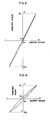
- FIG. 5 shows the torque detection characteristics observed when the torque sensor a was employed
- FIG. 6 shows the torque detection characteristics when the torque sensor a′ was employed.
- the torque sensors can be compared with each other in the magnitude of hysteresis on the basis of the ratio of output value at zero torque application to output value at maximum torque application ((a1 - a2)/(A1 - A2) ⁇ 100) (%). In detection sensitivity, they can be compared with each other on the basis of the ratio ( ⁇ mV/ ⁇ kgf ⁇ m) of detection output value increment ( ⁇ mV) to applied torque increment ( ⁇ kgf ⁇ m).
- the torque sensor a (FIG. 5) showed a hysteresis of 0.7% and a detection sensitivity of 37 (mV/kgf ⁇ m), whereas the torque sensor a′ (FIG. 6) showed a hysteresis of 3.5% and a detection sensitivity of 18 (mV/kgf ⁇ m).
- the torque sensor a which was of same construction as the torque sensor a except that it had no fine dents 2
- the torque sensor a which had fine dents 2 formed in the area of magneto-strictive section A on the shaft surface, showed good improvement in hysteresis in both hysteresis and detection sensitivity, that is, as low as about 1/5 in hysteresis and two times high in sensitivity.
- FIG. 7 shows the above mentioned test results with the torque sensors a and a′ and, in conjunction therewith, the results of tests with other specimen torque sensors b to d and b′ and d′ in hystersis (%) and detection sensitivity (mV/kgf ⁇ m).
- reference characters a - d and a′ - d′ designate individual torque sensors subjected to tests. Arrows directed from plot ⁇ toward plot ⁇ individually indicate, with respect to rotary shafts of same kind, directions of changes in torque detection hystersis and sensitivity due to the presence of fine dents.
- Hysteresis value (%) shown by individual plots are: b, 1.2% (b′, 21%); c, 1.8% (c′, 9.2%); d, 2% (d′, 10.8%).
- hysteresis is substantially reduced because of the presence of fine dents (downwardly changed to about 1/5 or lower in the case of sensors a, c, and d, and to about 1/20 in the case of sensor b); and with each of the sensors a, b, c, d, the hysteresis value is 2% or lower. Changes in detection sensitivity are different according to the material of the rotary shaft, but in all cases there can be seen a change for improvement because of the presence of fine dents 2.
- FIG. 8 illustrates, magnetic excitation and detection of magnetic permeability changes are carried out by employing an exciting magnetic head having exciting coils 12 wound on an open magnetic circuit type iron core 11, and a detecting magnetic haed having detecting coils 14 wound on an open magnetic circuit type iron core 13.
- numeral 15 designates an exciting high-frequency power supply
- 16 designates a synchronizing rectifier.
Landscapes
- Physics & Mathematics (AREA)
- Electromagnetism (AREA)
- General Physics & Mathematics (AREA)
- Force Measurement Appropriate To Specific Purposes (AREA)
- Power Steering Mechanism (AREA)
- Measuring Magnetic Variables (AREA)
- Devices For Use In Laboratory Experiments (AREA)
Abstract
Description
- The present invention relates to a magneto-strictive torque sensor for contactlessly detecting torque applied to a rotary shaft on the basis of a change in the magnetic permeability of the surface of the shaft.
- For contactless detection of torque applied to a rotary shaft of a rotary drive system in electric motors, machine tools, automobiles, and the like, magneto-stricitive torque sensors are widely used in which an alternating field is applied to the surface of the shaft so that a change in the magnetic permeability of the shaft surface which arises from application of torque to the rotary shaft is detected in terms of quantity of electricity.
- One known type of such magneto-strictive sensor is of the magnetic head system in which a coil winding (a magnetic head) having an open magnetic circuit type iron core, such as U-shaped iron core, is disposed adjacent the shaft to serve as exciting and detecting means, whereby a change in the magnetic permeability of the shaft surface in the direction of principal stress (a direction having an angular inclination of ±45 deg. relative to the axial direction of the shaft) which arises from application of torque to the shaft is detected ("Magnetic Measurement of Torque in a Rotating Shaft", The Review of Scientific Instruments, Vol. 25, No. 6, June 1954). Another known type is of the solenoid coil system such that uniaxial magnetic anisotropy in which a direction having an angular inclination relative to the axial direction of the rotary shaft is an axis of easy magnetization is imparted to the surface of the rotary shaft and, in proximity to the shaft portion to which the magnetic anisotropy is imparted, an exciting solenoid coil (exciting coil) and a solenoid coil for detecting changes in magnetic permeability (detecting coil) are arranged around the shaft so that an axial change in the magnetic permeability which is caused by torque application is detected ("A New Torque transducer using Stress Sensitive Amorphous Ribbons", IEEE Trans. on Mag., MAG-18, No. 6, 1769 - 9, 1982).
- For imparting magnetic anisotropy to the surface of the rotary shaft in such torque sensor of the solenoid coil system, there is known a method in which, as described in Japanese Patent Laid Open Publication No. 63-252487, for example, a plurality of belt-like hardened sections parallel to one another in a direction having an angular inclination relative to the axial direction of the shaft are formed on the shaft surface by laser quenching to create residual stress so that, as the effect of the stress, magnetic anisotropy is imparted to the shaft surface. Among other known methods there is one described in Japanese Patent No. 169326, for example, in which a plurality of spiral grooves parallel to one another are formed on the shaft surface by rolling or otherwise so that, as the configurational effect of the grooves, shape magnetic anisotropy is given to the shaft surface.
- Changes in the spontaneous magnetization of a ferromagnetic material which are caused by external magnetic field and/or stress acting on the rotary shaft include the process of magnetization due to magnetic domain wall displacement and the process of magnetization due to rotational magnetization which follows the first mentioned domain wall displacement. The process of magnetization due to rotational magnetization is mainly reversible. The process of magnetization due to magnetic domain wall displacement includes the process of reversible magnetization and the process of irreversible magnetization. Unless the external magnetic field and/or active stress is extremely small or unless it is noticeably large, the process of magnetization due to magnetic domain wall displacement is irreversible. This is attributable to the fact that magnetic domain wall displacement is hampered by microfine foreign matters (impurities), grain boundaries, lattice defects, etc. which are present in multiplicity in the ferromagnetic material. Unlike the process of reversible magnetization, the process of magnetization in which magnetic domain wall displacement is largely non-reversible involves hysteresis.
- In actual torque sensors, magnetic field applied to the surface of the rotary shaft is usually faint (generally not more than 10 Oe) and, therefore, the process of magnetization on the surface of a conventional rotary shaft made of a magnetically soft material of high-strength (coercive force Hc: about 10 - 20 Oe) is largely of irreversible magnetization due to magnetic domain wall displacement. As such, hysteresis cannot be avoided in the process of magnetization. The hysteresis in the process of magnetization appears as hysteresis in the detection characteristics of the torque sensor, thus adversely affecting the accuracy of torque detection.
- On the surface of the rotary shaft there are present not a few defects, such as burrs and hair cracks, though extremely small, which were produced in the machining and groove forming stages. These microdefects can be a cause of hysteresis in the torque detection characteristics or reduced sensitivity. Fatigue of the material of the rotary shaft due to repeated application of torque to the shaft, and intergranular slip due to application of large torque are also likely to cause increased hysteresis in torque detection and reduced detection sensitivity.
- It is an object of the invention to convert the process of magnetization on the surface of a rotary shaft into a process of magnetization which is mainly of rotational magnetization less liable to hysteresis in magnetization and to eliminate microdefects on the surface and provide improved resistance to intergranular slip on the surface layer of the shaft, thereby to minimize possible hysteresis in torque detection characteristics and obtain improved detection sensitivity.
- In order to accomplish the foregoing object, the present invention provides a magneto-strictive torque sensor of the type in which an exciting magnetic field is applied to a megneto-anisotropic zone formed on the surface of a predetermined region of a rotary shaft so that a change in the magnetic permeability of the magneto-anisotropic zone which arises from torque being applied to the rotary shaft is contactlessly detected by magnetic detecting means in terms of quantity of electricity, characterized in that fine dents and retainer areas for retaining residual compressive stress due to the fine dents are formed on the surface of the rotary shaft over a predetermined region including the magneto-anisotropic zone so that they are substantially uniformly distributed over the region.
- Fine dents on the surface of the rotary shaft are formed by shot peening, a process in which rigid spherical materials, such as pig iron and cast steel, of fine particle size are sprayed onto the shaft surface by utilizing compressed air or centrifugal force, or by rolling or knurling, a process in which a roll forming tool having a multiplicity of fine protrusions on the surface thereof is pressed against the shaft surface (and where required, such pressing is repeated.)
- Through the provision of fine dents formed on the surface of a ferromagnetic material, magnetic domains parallel to the tensile residual stress around the dents are stabilized and, as the effect of residual stress introduced through the formation of the dents, a stabilized region of magnetic domains which generally concentrically encompasses the dents is formed. It is known that the peripheral area of the dents is little subject to magnetic domain wall displacement in the change process of spontaneous magnetization under external magnetic field or stress acting on the shaft and the magnetization of the area takes a magnetization process which is mainly of reversible rotational magnetization (see, for example, "Jiseitai Handbook (Handbook of Magnetic Material)", p895, 1975, Asakura Publishing Co., Japan).
- Therefore, in that region on the surface of the rotary shaft in which a multiplicity of fine dents are formed in a minutely distributed pattern, the process of magnetization which takes place through the application of exciting magnetic field and torque is different from that in the case where no fine dents is present, in the fact that the process involves less magnetization due to magnetic domain wall displacement and is largely of reversible rotational magnetization, with the result of reduced hysteresis in the process of magnetization. As a consequence of the reduced hysteresis due to the formation of the fine dents, torque detection in the above mentioned region as an excitation/detection region involves less hysteresis in the detection characteristics thereof.
- On the surface layer of the rotary shaft fabricated through the process of machining and groove forming there are scatteringly present a multiplicity of microdefects, such as burrs and hair cracks, produced in the course of machining and groove forming, which can be a cause of increased hysteresis and reduced detection sensitivity as already noted. However, by virtue of the fine dents formed on the surface of the shaft, those microdefects are diminished or eliminated and as a result the process of torque detction involves less hysteresis and shows improved sensitivity. This effect is particularly noticeable where shot peening is applied. Where rolling or knurling is carried out by employing a rolling tool, a favorable result can be obtained as well by repeating the process.
- The surface of the rotary shaft in the region in which a multiplicity of fine dents are scatteringly formed has a metallic texture compressed and densified by dent forming. The surface layer of the shaft is rendered rigid as a result of work hardening due to the process of dent forming. Such densification by compression and hardening of the surface layer are also effective in increasing the fatigue resistance and intergranular slip resistance of the surface layer and result in reduced hysteresis in torque detection characteristics.
- Fine dent forming on the predetermined region of the rotary shaft surface may be carried out after the required tempering steps, such as heat treatment and carburization, with respect to the rotary shaft, or where uniaxial magnetic anisotropy is to be given to the surface of the rotary shaft, such dent forming may be carried out after the required step for giving such magnetic anisotropy is effected. Where spiral grooves are to be formed on the shaft surface by rolling or knurling, a rolling tool (die) having a multiplicity of protrusions scatteringly formed on its face is employed for the purpose, whereby spiral grooves and fine dents can be simultaneously formed.
- Fine dents formed on the shaft surface may not necessarily be of strictly regular arrangement; they may be acceptable if they are substantially uniformly distributed. The diameter of each of the dents may be generally of the order of 0.1 to 1 mm. The coverage of the dents on the surface area (percentage of the area occupied by the dents to the area of the predetermined surface region) is preferably not less than 70 %, more preferably not less than 90 %. A depth of not more than 0.1 mm is sufficient for the fine dents; there is no particular need for any greater depth. Considering the fact that the depth (skin depth) of a passage within the shaft for a magnetic flux applied to the shaft surface by the frequency (about 10 kHz to 50 kHz) of a normally used exciting current is about 0.1 mm or less, it is well possible to provide the skin of the shaft, as a magnetic path, with above mentioned effect of fine-dent formation by forming fine dents of about 0.1 mm or less in depth.
- The material of the rotary shaft to which the invention is applied is not particularly limited. Materials useful for the purpose include various different materials, such as carbon steel, chrome alloy steel, nickel-chrome alloy steel, chrome-molybdenum alloy steel, nickel-chrome-molybdenum alloy steel, and maraging steel.
- The system for magnetic excitation of the rotary shaft surface and detection of changes in magnetic permeability may be of a solenoid coil system using a solenoid coil concentrically wound along the outer periphery of the rotary shaft or may be of a magnetic head system using a magnetic head with a coil winding placed on a U-shaped iron core. For purposes of excitation/detection, any circuit configuration may be employed. In the torque sensor arrangement of the solenoid coil system in one embodiment to be described hereinafter, spiral grooves are formed in the surface of the rotary shaft to provide uniaxial magnetic anisotropy in which the direction of the angular inclination of the spiral grooves constitutes an axis of easy magnetization. Of course, such uniaxial magnetic anisotropy may be provided by any other suitable method. For example, a plurality of belt-like hardened sections which are angularly inclined relative to the axial direction are formed by laser quenching at a certain pitch in a circumferential direction, or belt-like carburized sections inclined angularly relative to the axial direction are formed at a certain pitch in a circumferential direction, to arrange for provision of uniaxial magnetic anisotropy through the formation of such inclined belt-like hardened sections or belt-like carburized sections. Further, the torque sensor in the embodiment to be explained hereinafter has a differential-type construction in which two adjacent zones on the surface of the rotary shaft are provided with different uniaxial magnetic anisotropies which are equally angularly inclined relative to the axial direction but are inclined in reverse relation to each other so that changes in magnetic permeability in the respective zones are differentially sensed. However, such construction is not always required. Of course, it is possible to construct an excitation/detection circuit which detects the magnitude of torque applied to the rotary shaft and the direction of torque application, positive or negative (forward or reverse), on the basis of a change in magnetic permeability in only one zone provided with uniaxial magnetic anisotropy.
- The arrangement described above have fine dents formed on the surface of the rotary shaft itself. However, if the shaft is formed of a material having minor or non magneto-strictive effect, it is possible to arrange that a sleeve made of a ferro-magnetic metal having greater magneto-strictive effect is firmly fitted and fixed to the desired surface portion of the rotary shaft by welding, bonding, shrinkage fitting, cold fitting, or otherwise so that stress resulting from the torque applied to the rotary shaft is transmitted to the sleeve, whereby a change in the magnetic permeability of the sleeve is detected. In this case, by forming fine dents on the surface of the sleeve it is possible to obtain improved hysteresis and improved sensitivity as in above described case. Therefore, the surface of the rotary shaft on which fine dents are formed, when referred to as such, means not only the surface of the shaft itself, but also the surface of the sleeve as a magneto-strictive member fitted fixedly to the shaft.
- According to the invention, the hysteresis involved in the detection of torque of the rotary shaft is smaller and the detecting sensitivity is higher. With the improved hysteresis and sensitivity, highly accurate torque detection is possible and thus the reliability of torque detection in rotary drive system control is enhanced.
- The principle of the invention that by forming fine dents on the surface of a ferro-magnetic element the magnetic properties of the element are changed is applicable not only to torque detection with respect to rotary shafts, but also to maintenance of various structures and management of changes of material characteristics with time and age through utilization of magneto-strictive phenomena. For example, when carrying out load measurement and maintenance of buildings, bridges, etc., maintenance and preliminary testing of plant equipment and high-pressure tanks, and/or measurement of residual stress distribution in welded structures, improved measurement accuracy and improved measurement reliability can be obtained by arranging that fine dents are formed at spots required to be measured.
-
- FIG. 1 is a perspective view of a rotary shaft having fine dents formed on its surface over a predetermined region in accordance with the invention;
- FIG. 2 is a perspective view of a rotary shaft having a multiplicity of spiral grooves formed thereon and fine dents formed over a predetermined region in accordance with the invention;
- FIG. 3 is a sectional view schematically showing a rotary shaft in a magneto-strictive torque sensor according to the invention and exciting/detecting solenoid coils arranged around the rotary shaft;
- FIG. 4 is a schematic illustration showing an excitation/detection circuit in the magneto-strictive torque sensor of the invention;
- FIG. 5 is a graphical representation showning the torque detection characteristics of a magneto-strictive torque sensor representing one embodiment of the invention;
- FIG. 6 is a graph showing the torque detection characteristics of a magneto-strictive torque sensor in a comparative example;
- FIG. 7 is a graph showing hysteresis and sensitivity in torque detection when the embodiment of the invention is used, in comparison with those with the magneto-strictive torque sensor in the comparative example; and
- FIG. 8 is a perspective view of a magneto-strictive torque sensor having the rotary shaft shown in Fig. 1 and exciting/detecting heads arranged in conjunction therewith.
- FIG. 1 shows an embodiment in which a multiplicity of
fine dents 2 are formed on the surface of a rotary shaft 1 so that they are distributed over a predetermined region A. FIG. 2 shows another embodiment in which a multiplicity ofspiral grooves 3 are circumferentially formed in spaced relation and in parallel to one another and in which a multiplicity offine dents 2 are scatteringly formed on the rotary shaft in the region in which the spiral grooves are formed and also in adjacent areas. - An embodiment incorporating the rotary shaft shown in Fig. 2 will now be described in detail.
- The following rotary shafts (a) to (d) (all with a shaft diameter of 30 mm) are prepared, and they are all formed on their respective surfaces with same sprial grooves and fine dents as shown in FIG. 2. A solenoid coil type excitation/detection circuit as shown in FIG. 3 is arranged in conjunction with each of the rotary shaft to form a torque sensor. Torque detecting test was carried out with respect to each sensor.
-
- (i) Shaft material: 4.3% Ni nickel-chrome-molybdenum steel
- (ii) Heat treatment: primary hardening (930°C, oil quenched) → secondary hardening (850°C, oil quenched) → tempered (175°C × 4hrs, air cooled)
- (iii) Tensile strength: 110 kg f/mm², hardness (HRC): 40
- (iv) Magneto-strictive constant (λs): 21 × 10⁻⁶
-
- (i) Shaft material: 14% Ni nickel maraging steel
- (ii) Heat treatment: solution treatment (900°C × 1 hr, air cooled) → aging (480°C × 3 hrs, air cooled)
- (iii) Tensile strength: 170 kg f/mm², hardness (HRC): 49
- (iv) Magneto-strictive constant (λs): 22 × 10⁻⁶
-
- (i) Shaft material: 8.5% Ni nickel-chrome-molybdenum steel
- (ii) Heat treatment: quenching (830°C air cooled) → tempered (560°C air cooled)
- (iii) Tensile strength: 140 kg f/mm², hardness (HRC): 43
- (iv) Magneto-strictive constant (λs): 27 × 10⁻⁶
-
- (i) Shaft material: 8.5% Ni nickel maraging steel
- (ii) Heat treatment: solution treatment (830°C × 1 hr, air cooled) → aging (515°C × 3 hrs, air cooled)
- (iii) Tensile strength: 120 kg f/mm², hardness (HRC): 35
- (iv) Magneto-strictive constant (λs): 21.5 × 10⁻⁶
-
- (i) Groove forming: In two adjacent areas (A), (A) on the shaft surface were formed, by roll forming process, series of spiral grooves having an angular inclination of 45 deg. relative to the axial direction of the shaft and oriented in opposite directions. In FIG. 3, belt-shaped inclined patterns formed in two areas (A), (A) on the rotary shaft 1 represent
spiral grooves
Groove depth: about 1 mm, groove interval: about 2 mm, groove length: about 10 mm. - (ii) Formation of fine dents: Steel balls (diameter of 0.1 to 0.6 mm) were used as shots. Shots spray velocity was 62 m/sec. In FIG. 3, dots scattered in the areas (A), (A) represent
fine dents 2 formed by shot peening. The depth of each impression was about 0.1 mm or less. The shot coverage (area percentage) was 95 to 98%. - Excitation/detection circuits were individually arranged on the rotary shafts (a) to (d) to from torque sensors (a) to (d). FIG. 3 shows the disposition of each excitation/detection circuit in relation to the corresponding rotary shaft 1. FIG. 4 shows the arrangement of the excitation/detection circuit. In the description to follow, the two areas (A), (A) having
spiral grooves fine dents 2 formed therein, on the surface of the shaft, are each referred to as "magneto-strictive sections". - In FIG. 3,
numeral 6 designates a solenoid coil (exciting coil) for applying exciting field to the "magneto-strictive sections" (A), (A), and 8, 8 designate solenoid coils (detecting coils) for detecting changes in the magnetic permeability of the "magneto-strictive sections" (A), (A) which take place when torque T is applied to the rotary shaft 1. Theexciting coil 6 and the detectingcoils casing 5, being positioned in proximity to the rotary shaft 1. As FIG. 4 shows, the exitingcoil 6 is connected to a high-frequencyexcitation power supply 7. The detecting coils 8 and 8 are connected together in reverse polarity to detect differentially the changes of magnetic permeabilities of the two corresponding magneto-strictive sections (A), (A), their terminals being connected to a synchronizing rectifier 9. In the detectingcoils exciting coil 6, the difference between the induced voltages being outputted as a DC voltage from the synchronizing rectifier 9. - In this torque sensor, when no torque is applied to the rotary shaft, the magnetic permeabilities of the two magneto-strictive sections (A), (A) are equal; therefore, an induced voltage developing in one detecting
coil 8 and an induced voltage developing in the other detectingcoil 8 are negated, one against the other, there being thus no output. When torque T is applied to the rotary shaft 1, one of the two magneto-strictive sections (A), (A) is mainly subject to tensile force and the other is mainly subject to compressive force. As a result, the magnetic permeability of the one magneto-strictive section is increased, while that of the other is decreased. Because of this differential change in magnetic permeability, the induced voltage at the one detectingcoil 8 is increased and that at the other detectingcoil 8 is decreased. This difference is outputted as a DC voltage from the synchronizing rectifier 9, and the magnitude of the applied torque T is detected from the magnitude of the output value, and the direction in which the torque has been applied is detected from the positive or negative sign of the output value. - As comparative example, rotary shafts a′ to d′ were prepared in same way as the foregoing rotary shafts a to d, except that formation by shot peening of fine dents on the surface of the region in which spiral grooves were formed was omitted. Same excitation/detection circuit as above described was arranged on each of the rotary shafts a′ to d′. Thus, torque sensors a′ to d′ were formed.
- With respect to each of the torque sensors a to d and also to each of the torque sensors a′ to d′, torque detecting tests were carried out by applying rated torque under magnetic field application to the magneto-strictive sections from a high-frequency power supply (exciting current: 40 mA rms, frequency: 10 kHz).
- FIG. 5 shows the torque detection characteristics observed when the torque sensor a was employed, and similarly FIG. 6 shows the torque detection characteristics when the torque sensor a′ was employed. The torque sensors can be compared with each other in the magnitude of hysteresis on the basis of the ratio of output value at zero torque application to output value at maximum torque application ((a₁ - a₂)/(A₁ - A₂) × 100) (%). In detection sensitivity, they can be compared with each other on the basis of the ratio (ΔmV/Δkgf·m) of detection output value increment (ΔmV) to applied torque increment (Δkgf·m).
- The torque sensor a (FIG. 5) showed a hysteresis of 0.7% and a detection sensitivity of 37 (mV/kgf·m), whereas the torque sensor a′ (FIG. 6) showed a hysteresis of 3.5% and a detection sensitivity of 18 (mV/kgf·m). In other words, as compared with the torque sensor a′, which was of same construction as the torque sensor a except that it had no
fine dents 2, the torque sensor a, which hadfine dents 2 formed in the area of magneto-strictive section A on the shaft surface, showed good improvement in hysteresis in both hysteresis and detection sensitivity, that is, as low as about 1/5 in hysteresis and two times high in sensitivity. - FIG. 7 shows the above mentioned test results with the torque sensors a and a′ and, in conjunction therewith, the results of tests with other specimen torque sensors b to d and b′ and d′ in hystersis (%) and detection sensitivity (mV/kgf·m). In FIG. 7, reference characters a - d and a′ - d′ designate individual torque sensors subjected to tests. Arrows directed from plot ○ toward plot ● individually indicate, with respect to rotary shafts of same kind, directions of changes in torque detection hystersis and sensitivity due to the presence of fine dents. Hysteresis value (%) shown by individual plots are: b, 1.2% (b′, 21%); c, 1.8% (c′, 9.2%); d, 2% (d′, 10.8%). With individual torque sensors, hysteresis is substantially reduced because of the presence of fine dents (downwardly changed to about 1/5 or lower in the case of sensors a, c, and d, and to about 1/20 in the case of sensor b); and with each of the sensors a, b, c, d, the hysteresis value is 2% or lower. Changes in detection sensitivity are different according to the material of the rotary shaft, but in all cases there can be seen a change for improvement because of the presence of
fine dents 2. - In the case of the rotary shaft shown in FIG. 1, when torque is applied to the rotary shaft 1, "magnetic anisotropy due to applied stress" is imparted to the predetermined region A under the stress arising from the torque. Now, the rotary shaft 1 prior to the torque application has magnetic isotropy. As torque is applied, the direction of principal tensile stress due to the torque, that is, one direction of angular inclination of 45 deg. relative to the axis of the rotary shaft 1, becomes the direction of axis of easy magnetization. On the contrary, the other direction normal to the axis of easy magnetization, that is, the direction of principal compressive stress, becomes the hard axis of magnetization. Accordingly, magnetization concentrates in the direction of the easy axis of magnetization under such applied tensile stress and little magnetization takes place in the direction of the hard axis of magnetization, magnetic anisotropy being thus imparted.
- In such case, as FIG. 8 illustrates, magnetic excitation and detection of magnetic permeability changes are carried out by employing an exciting magnetic head having
exciting coils 12 wound on an open magnetic circuittype iron core 11, and a detecting magnetic haed having detectingcoils 14 wound on an open magnetic circuittype iron core 13. In FIG. 8, numeral 15 designates an exciting high-frequency power supply, and 16 designates a synchronizing rectifier.
Claims (11)
that fine dents and retainer areas for retaining residual compressive stress due to the fine dents are formed on the surface of the rotary shaft over a predetermined region including the magneto-anisotropic zone so that they are substantially uniformly distributed over the region.
that fine dents and retainer areas for retaining residual compressive stress due to the fine dents are formed on the surface of the measuring object so that they are substantially uniformly distributed over the region.
Applications Claiming Priority (2)
| Application Number | Priority Date | Filing Date | Title |
|---|---|---|---|
| JP42544/89 | 1989-02-22 | ||
| JP1042544A JPH02221830A (en) | 1989-02-22 | 1989-02-22 | Magnetostriction type torque sensor |
Publications (3)
| Publication Number | Publication Date |
|---|---|
| EP0384042A2 true EP0384042A2 (en) | 1990-08-29 |
| EP0384042A3 EP0384042A3 (en) | 1991-04-03 |
| EP0384042B1 EP0384042B1 (en) | 1993-04-14 |
Family
ID=12639004
Family Applications (1)
| Application Number | Title | Priority Date | Filing Date |
|---|---|---|---|
| EP89201428A Expired - Lifetime EP0384042B1 (en) | 1989-02-22 | 1989-06-02 | Magneto-strictive torque sensor |
Country Status (8)
| Country | Link |
|---|---|
| US (1) | US4933580A (en) |
| EP (1) | EP0384042B1 (en) |
| JP (1) | JPH02221830A (en) |
| KR (1) | KR940000769B1 (en) |
| CN (1) | CN1083574C (en) |
| DE (1) | DE68906017T2 (en) |
| ES (1) | ES2039833T3 (en) |
| RU (1) | RU1797698C (en) |
Cited By (14)
| Publication number | Priority date | Publication date | Assignee | Title |
|---|---|---|---|---|
| EP1477788A2 (en) * | 2003-05-12 | 2004-11-17 | HONDA MOTOR CO., Ltd. | Magnetostrictive coat forming method, magnetostrictive torque sensor manufacturing method, and electric power steering apparatus including such a sensor |
| EP2397829B1 (en) | 2010-06-21 | 2016-04-27 | PolyResearch AG | Dynamic signal torque sensor |
| DE102017107716A1 (en) | 2017-04-03 | 2018-10-04 | Trafag Ag | Torque transmitter and torque sensor as well as manufacturing methods and measuring methods |
| WO2019197500A1 (en) | 2018-04-13 | 2019-10-17 | Trafag Ag | Method for producing a planar coil assembly and a sensor head provided with same |
| DE102018115008A1 (en) | 2018-06-21 | 2019-12-24 | Trafag Ag | Load measurement arrangement, manufacturing process therefor and thus feasible load measurement process |
| DE102018115713A1 (en) | 2018-06-28 | 2020-01-02 | Trafag Ag | Method, device and arrangement for load measurement on a test object |
| WO2020039013A1 (en) | 2018-08-21 | 2020-02-27 | Trafag Ag | Load-measuring device and load-measuring method |
| DE102018123800A1 (en) * | 2018-09-26 | 2020-03-26 | Trafag Ag | Load measuring arrangement with a load element and a load sensor, manufacturing method and load measuring method |
| DE102018124644A1 (en) * | 2018-10-05 | 2020-04-09 | Trafag Ag | Bottom bracket arrangement and sports equipment provided with it |
| DE102019102454B3 (en) | 2019-01-31 | 2020-08-06 | Trafag Ag | Arrangement and method for measuring a mechanical load on a test object while detecting changes in the magnetic field |
| DE102019108898A1 (en) * | 2019-04-04 | 2020-10-08 | Trafag Ag | Device and arrangement for measuring the load on a test object, in particular a chassis component |
| DE102019112795A1 (en) * | 2019-05-15 | 2020-11-19 | Trafag Ag | Load measuring arrangement, manufacturing method for this and load measuring method that can be carried out with it |
| US11927499B2 (en) | 2018-06-21 | 2024-03-12 | Trafag Ag | Load measuring arrangement, method for producing said arrangement and load measuring method which can be carried out with said arrangement |
| DE102022129926A1 (en) | 2022-11-11 | 2024-05-16 | Trafag Ag | Sensor head for load measuring device with magnetic coils |
Families Citing this family (45)
| Publication number | Priority date | Publication date | Assignee | Title |
|---|---|---|---|---|
| US5205145A (en) * | 1989-09-25 | 1993-04-27 | Kubota Corporation | Method of producing torque sensor shafts |
| JPH0450741A (en) * | 1990-06-19 | 1992-02-19 | Kubota Corp | Torque sensor shaft |
| JP2781071B2 (en) * | 1991-01-30 | 1998-07-30 | 株式会社クボタ | Manufacturing method of magnetostrictive torque sensor shaft |
| SE9102122D0 (en) * | 1991-07-08 | 1991-07-08 | Skf Nova Ab | SENSOR RESPECTIVE PROCEDURE BEFORE SEATING TORQUE AND / OR FORCES |
| US5351555A (en) * | 1991-07-29 | 1994-10-04 | Magnetoelastic Devices, Inc. | Circularly magnetized non-contact torque sensor and method for measuring torque using same |
| EP0609463B1 (en) * | 1992-08-24 | 1999-11-17 | Kubota Corporation | Method for manufacturing magnetostriction type torque sensor shaft, and the shaft |
| US5816599A (en) * | 1995-06-14 | 1998-10-06 | Koyo Electronics Industries Co., Ltd | Bicycle torque detection apparatus and bicycle including the same |
| JP4217321B2 (en) * | 1997-12-26 | 2009-01-28 | ヤマハ発動機株式会社 | Load detection device |
| GB0007532D0 (en) * | 2000-03-28 | 2000-05-17 | Fast Technology Gmbh | Magnetic-based force/torque sensing |
| JP3464195B2 (en) * | 2000-06-23 | 2003-11-05 | 株式会社村田製作所 | Magnetic sensor, magnetic sensor device, and torque sensor |
| US6494102B2 (en) | 2001-01-12 | 2002-12-17 | Trw Inc. | Magnetostrictive stress sensor |
| DE10111979A1 (en) * | 2001-03-13 | 2002-09-19 | Weber Schraubautomaten Gmbh | Screwdriver with automatic screw supply for use in a production environment has a magnetic arrangement for measuring torque, rotation angle, etc. so that additional measurement apparatus is not required |
| JP2003114103A (en) * | 2001-10-02 | 2003-04-18 | Koyo Seiko Co Ltd | Angle-of-rotation detector, torque detector and steering gear |
| US6823746B2 (en) * | 2002-07-11 | 2004-11-30 | Visteon Global Technologies, Inc. | Magnetoelastic torque sensor for mitigating non-axisymmetric inhomogeneities in emanating fields |
| US6865959B2 (en) * | 2002-09-18 | 2005-03-15 | Siemens Vdo Automotive Corporation | Torque sensor with contoured magnetoelastic element |
| US20040154412A1 (en) * | 2003-02-10 | 2004-08-12 | Viola Jeffrey L. | Cross-axial sensor for measuring magnetic fields emanating from magnetoelastic shafts |
| US8029749B2 (en) | 2004-09-21 | 2011-10-04 | Technip France S.A.S. | Cracking furnace |
| US7749462B2 (en) | 2004-09-21 | 2010-07-06 | Technip France S.A.S. | Piping |
| GB0420971D0 (en) | 2004-09-21 | 2004-10-20 | Imp College Innovations Ltd | Piping |
| US7409878B2 (en) * | 2005-04-08 | 2008-08-12 | Honeywell International Inc. | Torqueshaft magnetic field measurement systems for gas turbine engines |
| JP2007086018A (en) * | 2005-09-26 | 2007-04-05 | Hitachi Cable Ltd | Magnetostrictive torque sensor |
| JP4283263B2 (en) * | 2005-10-20 | 2009-06-24 | 本田技研工業株式会社 | Manufacturing method of magnetostrictive torque sensor |
| WO2007118512A1 (en) * | 2006-04-13 | 2007-10-25 | BSH Bosch und Siemens Hausgeräte GmbH | Machine for washing and/or drying laundry |
| CN101191749B (en) * | 2006-11-30 | 2011-08-10 | 西门子Vdo汽车公司 | Torque sensor hysteresis reduction |
| JP5094101B2 (en) * | 2006-12-06 | 2012-12-12 | シーメンス ヴィディーオー オートモーティヴ コーポレイション | Solenoid magnetometer |
| DE102007014016A1 (en) * | 2007-03-23 | 2008-09-25 | Schaeffler Kg | Bearing for supporting a body rotatable about an axis with a cover body |
| GB0817219D0 (en) | 2008-09-19 | 2008-10-29 | Heliswirl Petrochemicals Ltd | Cracking furnace |
| CN102401708A (en) * | 2011-11-24 | 2012-04-04 | 北京科技大学 | Torque sensor based on magnetostriction effect and torque measuring method |
| DE102014100124A1 (en) * | 2014-01-08 | 2015-07-09 | Claas Selbstfahrende Erntemaschinen Gmbh | Device for detecting the state of a machine element |
| DE102014216375B3 (en) * | 2014-08-19 | 2015-12-03 | Schaeffler Technologies AG & Co. KG | Shaft for enabling a torque measurement and method for producing such a shaft |
| JP6376028B2 (en) * | 2015-04-14 | 2018-08-22 | 日立金属株式会社 | Torque sensor |
| DE102015206664B3 (en) * | 2015-04-14 | 2016-07-28 | Schaeffler Technologies AG & Co. KG | Hollow machine element and arrangement for measuring a force or a moment |
| DE102015209286A1 (en) | 2015-05-21 | 2016-11-24 | Schaeffler Technologies AG & Co. KG | Arrangement and method for measuring a force or a moment with at least two spaced magnetic field sensors |
| CN106368815B (en) * | 2016-10-12 | 2018-10-16 | 广西玉柴机器股份有限公司 | A kind of combined type signal panels and preparation method thereof |
| JP6740908B2 (en) * | 2017-01-11 | 2020-08-19 | 日立金属株式会社 | Method for manufacturing shaft for magnetostrictive torque sensor |
| EP3620364A4 (en) * | 2017-05-05 | 2021-03-10 | Giant Electric Vehicle Kunshan Co., Ltd | Device for detecting vehicle operation parameters |
| EP3460437B1 (en) * | 2017-09-25 | 2021-10-27 | ETA SA Manufacture Horlogère Suisse | Dynamic torque and/or force calibration device |
| JP2019117103A (en) * | 2017-12-27 | 2019-07-18 | アズビル株式会社 | Correction method of zero point error in torque sensor |
| CN108519180A (en) * | 2018-03-31 | 2018-09-11 | 天津大学 | A kind of torque measuring method based on electronickelling elastic shaft |
| CN109556774B (en) * | 2018-11-07 | 2020-07-07 | 北京航空航天大学 | Nondestructive monitoring system and monitoring method for residual stress in ferromagnetic steel |
| CN111060227B (en) * | 2019-11-27 | 2021-01-29 | 成都航大新材料有限公司 | In-situ stress detection and repair integrated system |
| JP7357570B2 (en) * | 2020-03-03 | 2023-10-06 | 株式会社プロテリアル | Magnetostrictive torque sensor detection circuit and detection method |
| CN111537122A (en) * | 2020-05-08 | 2020-08-14 | 上海钧嵌传感技术有限公司 | Detection shaft of torque detection sensor and preparation method |
| DE102023102593A1 (en) | 2023-02-02 | 2024-08-08 | Zf Cv Systems Global Gmbh | Electromechanical brake actuator for a braking system, and commercial vehicle with such |
| CN118577398A (en) * | 2024-08-02 | 2024-09-03 | 山东华盛创新纺织科技有限公司 | Yarn raw material centrifugal treatment device |
Citations (2)
| Publication number | Priority date | Publication date | Assignee | Title |
|---|---|---|---|---|
| EP0229688A2 (en) * | 1986-01-10 | 1987-07-22 | Honda Giken Kogyo Kabushiki Kaisha | Mechanical property sensor element and method for making the same |
| EP0270122A2 (en) * | 1986-12-05 | 1988-06-08 | Mag Dev Inc. | Magnetoelastic torque transducer |
Family Cites Families (7)
| Publication number | Priority date | Publication date | Assignee | Title |
|---|---|---|---|---|
| US3505657A (en) * | 1965-07-20 | 1970-04-07 | Us Navy | Torsional delay line and impressed flux linkage interaction device |
| GB1151820A (en) * | 1966-12-09 | 1969-05-14 | Arenco Electronics Ab | A Device for Measuring Mechanical Forces. |
| US4122708A (en) * | 1976-03-31 | 1978-10-31 | Simmonds Precision Products, Inc. | Capacitive proximity sensors |
| US4716556A (en) * | 1981-07-23 | 1987-12-29 | Allied-Signal Inc. | Magnetostrictive acoustic transducer |
| DE3605036A1 (en) * | 1985-04-10 | 1986-10-16 | Gerd 3167 Burgdorf Hörmansdörfer | METHOD AND DEVICE FOR DETERMINING THE CLAMPING POINT OF A STRING IN A DRILL HOLE |
| JPS63210735A (en) * | 1987-02-27 | 1988-09-01 | Honda Motor Co Ltd | Mechanical quantity detecting element |
| JPH0745704B2 (en) * | 1987-05-28 | 1995-05-17 | 大同特殊鋼株式会社 | Measured shaft for torque sensor |
-
1989
- 1989-02-22 JP JP1042544A patent/JPH02221830A/en active Pending
- 1989-06-02 ES ES198989201428T patent/ES2039833T3/en not_active Expired - Lifetime
- 1989-06-02 DE DE89201428T patent/DE68906017T2/en not_active Expired - Lifetime
- 1989-06-02 EP EP89201428A patent/EP0384042B1/en not_active Expired - Lifetime
- 1989-06-05 US US07/361,947 patent/US4933580A/en not_active Expired - Lifetime
- 1989-06-21 CN CN89104247A patent/CN1083574C/en not_active Expired - Lifetime
- 1989-06-22 RU SU894614358A patent/RU1797698C/en active
- 1989-06-22 KR KR1019890008646A patent/KR940000769B1/en not_active IP Right Cessation
Patent Citations (2)
| Publication number | Priority date | Publication date | Assignee | Title |
|---|---|---|---|---|
| EP0229688A2 (en) * | 1986-01-10 | 1987-07-22 | Honda Giken Kogyo Kabushiki Kaisha | Mechanical property sensor element and method for making the same |
| EP0270122A2 (en) * | 1986-12-05 | 1988-06-08 | Mag Dev Inc. | Magnetoelastic torque transducer |
Non-Patent Citations (4)
| Title |
|---|
| IEEE TRANSACTIONS ON MAGNETICS vol. MAG-18, no. 6, November 1982, pages 1767-1769, IEEE; K. HARADA et al.: "A New Torque Transducer Using Stress Sensitive Amorphous Ribbons" * |
| IEEE TRANSACTIONS ON VEHICULAR TECHNOLOGY vol. VT-31, no. 3, August 1982, pages 117-124, IEEE, New York, US; W.J. FLEMING: "Automotive Torque Measurement: A Summary of Seven Different Methods" * |
| IEEE TRANSCATIONS ON MAGNETICS vol. MAG-18, no. 6, November 1982, pages 1767-1769, IEEE; K. HARADA et al.: "A New Torque Transducer Using Stress Sensitive Amorphous Ribbons" * |
| REVIEW OF SCIENTIFIC INSTRUMENTS vol. 25, no. 6, June 1954, pages 603-607; R.A. BETH et al.: "Magnetic Measurement of Torque in a Rotating Shaft" * |
Cited By (25)
| Publication number | Priority date | Publication date | Assignee | Title |
|---|---|---|---|---|
| EP1477788A2 (en) * | 2003-05-12 | 2004-11-17 | HONDA MOTOR CO., Ltd. | Magnetostrictive coat forming method, magnetostrictive torque sensor manufacturing method, and electric power steering apparatus including such a sensor |
| EP1477788A3 (en) * | 2003-05-12 | 2004-12-29 | HONDA MOTOR CO., Ltd. | Magnetostrictive coat forming method, magnetostrictive torque sensor manufacturing method, and electric power steering apparatus including such a sensor |
| EP2397829B1 (en) | 2010-06-21 | 2016-04-27 | PolyResearch AG | Dynamic signal torque sensor |
| WO2018185018A1 (en) | 2017-04-03 | 2018-10-11 | Trafag Ag | Torque transmitter and torque sensor, manufacturing method and measuring method |
| DE102017107716B4 (en) | 2017-04-03 | 2018-11-29 | Trafag Ag | Torque transmitter and torque sensor as well as manufacturing methods and measuring methods |
| DE102017107716A1 (en) | 2017-04-03 | 2018-10-04 | Trafag Ag | Torque transmitter and torque sensor as well as manufacturing methods and measuring methods |
| US11422048B2 (en) | 2017-04-03 | 2022-08-23 | Trafag Ag | Torque transmitter and torque sensor, manufacturing method and measuring method |
| WO2019197500A1 (en) | 2018-04-13 | 2019-10-17 | Trafag Ag | Method for producing a planar coil assembly and a sensor head provided with same |
| DE102018114785A1 (en) | 2018-04-13 | 2019-10-17 | Trafag Ag | Method for producing a planar coil arrangement and a sensor head provided therewith |
| DE102018115008A1 (en) | 2018-06-21 | 2019-12-24 | Trafag Ag | Load measurement arrangement, manufacturing process therefor and thus feasible load measurement process |
| US11927499B2 (en) | 2018-06-21 | 2024-03-12 | Trafag Ag | Load measuring arrangement, method for producing said arrangement and load measuring method which can be carried out with said arrangement |
| DE102018115713B4 (en) | 2018-06-28 | 2022-08-04 | Trafag Ag | Method, device and arrangement for measuring the load on a test object |
| DE102018115713A1 (en) | 2018-06-28 | 2020-01-02 | Trafag Ag | Method, device and arrangement for load measurement on a test object |
| WO2020002390A1 (en) | 2018-06-28 | 2020-01-02 | Trafag Ag | Method, device and arrangement for load measurement on a test object |
| US11821804B2 (en) | 2018-06-28 | 2023-11-21 | Trafag Ag | Method, device and arrangement for load measurement on a test object |
| WO2020039013A1 (en) | 2018-08-21 | 2020-02-27 | Trafag Ag | Load-measuring device and load-measuring method |
| DE102018123800A1 (en) * | 2018-09-26 | 2020-03-26 | Trafag Ag | Load measuring arrangement with a load element and a load sensor, manufacturing method and load measuring method |
| DE102018124644B4 (en) | 2018-10-05 | 2020-06-04 | Trafag Ag | Bottom bracket arrangement and sports equipment provided with it |
| DE102018124644A1 (en) * | 2018-10-05 | 2020-04-09 | Trafag Ag | Bottom bracket arrangement and sports equipment provided with it |
| DE102019102454B3 (en) | 2019-01-31 | 2020-08-06 | Trafag Ag | Arrangement and method for measuring a mechanical load on a test object while detecting changes in the magnetic field |
| WO2020200775A1 (en) | 2019-04-04 | 2020-10-08 | Trafag Ag | Device and arrangement for measuring load on a test object, in particular a chassis component |
| DE102019108898A1 (en) * | 2019-04-04 | 2020-10-08 | Trafag Ag | Device and arrangement for measuring the load on a test object, in particular a chassis component |
| DE102019108898B4 (en) | 2019-04-04 | 2022-08-04 | Trafag Ag | Device and arrangement for measuring the load on a test object, in particular a chassis component |
| DE102019112795A1 (en) * | 2019-05-15 | 2020-11-19 | Trafag Ag | Load measuring arrangement, manufacturing method for this and load measuring method that can be carried out with it |
| DE102022129926A1 (en) | 2022-11-11 | 2024-05-16 | Trafag Ag | Sensor head for load measuring device with magnetic coils |
Also Published As
| Publication number | Publication date |
|---|---|
| EP0384042B1 (en) | 1993-04-14 |
| CN1045178A (en) | 1990-09-05 |
| DE68906017D1 (en) | 1993-05-19 |
| JPH02221830A (en) | 1990-09-04 |
| CN1083574C (en) | 2002-04-24 |
| ES2039833T3 (en) | 1993-10-01 |
| DE68906017T2 (en) | 1993-10-28 |
| US4933580A (en) | 1990-06-12 |
| KR900013287A (en) | 1990-09-05 |
| KR940000769B1 (en) | 1994-01-29 |
| EP0384042A3 (en) | 1991-04-03 |
| RU1797698C (en) | 1993-02-23 |
Similar Documents
| Publication | Publication Date | Title |
|---|---|---|
| EP0384042B1 (en) | Magneto-strictive torque sensor | |
| KR920006454B1 (en) | Magnetoelastic torque transducer | |
| US4760745A (en) | Magnetoelastic torque transducer | |
| Abuku | Magnetic studies of residual stress in iron and steel induced by uniaxial deformation | |
| US5280729A (en) | Magnetostrictive torque detecting apparatus | |
| KR20000069650A (en) | Collarless circularly magnetized torque transducer having two phase shaft and method for measuring torque using same | |
| Dobmann | Physical basics and industrial applications of 3MA–micromagnetic multiparameter microstructure and stress analysis | |
| US5107711A (en) | Torque sensor | |
| EP2250475B1 (en) | Biaxial stress measurement | |
| Buttle | Magnetic methods | |
| JPH0466863A (en) | Residual stress measuring method by steel working | |
| Ebine et al. | Magnetic measurement to evaluate material properties of ferromagnetic structural steels with planar coils | |
| US3782187A (en) | Magneto-elastic transducer for force measurement | |
| Fleming | Magnetostrictive torque sensors—Derivation of transducer model | |
| JP5081353B2 (en) | Torque transducer | |
| US5475305A (en) | Magnetic inspection probe for measurement of magnetic anisotropy | |
| Langman et al. | Estimation of residual stresses in railway wheels by means of stress-induced magnetic anisotropy | |
| JP2000009558A (en) | Magnetostriction type torque sensor | |
| JPH0710011B2 (en) | Magnetostrictive torque sensor | |
| Schröder | Magnetic Barkhausen effect and its application | |
| JPH05203507A (en) | Magnetostriction type torque sensor | |
| Sawalem et al. | Evaluation of Residual Stresses in Grinding by Magnetic Barkhausen Noise | |
| Mäkipää | Surface characterization of ground surfaces: effects of grinding | |
| JP3759289B2 (en) | Stress sensor plate and stress measurement method using the same | |
| JP2571422B2 (en) | Magnetostrictive torque sensor |
Legal Events
| Date | Code | Title | Description |
|---|---|---|---|
| PUAI | Public reference made under article 153(3) epc to a published international application that has entered the european phase |
Free format text: ORIGINAL CODE: 0009012 |
|
| AK | Designated contracting states |
Kind code of ref document: A2 Designated state(s): DE ES FR GB IT SE |
|
| 17P | Request for examination filed |
Effective date: 19901206 |
|
| PUAL | Search report despatched |
Free format text: ORIGINAL CODE: 0009013 |
|
| AK | Designated contracting states |
Kind code of ref document: A3 Designated state(s): DE ES FR GB IT SE |
|
| 17Q | First examination report despatched |
Effective date: 19911204 |
|
| GRAA | (expected) grant |
Free format text: ORIGINAL CODE: 0009210 |
|
| AK | Designated contracting states |
Kind code of ref document: B1 Designated state(s): DE ES FR GB IT SE |
|
| REF | Corresponds to: |
Ref document number: 68906017 Country of ref document: DE Date of ref document: 19930519 |
|
| ITF | It: translation for a ep patent filed | ||
| ET | Fr: translation filed | ||
| REG | Reference to a national code |
Ref country code: ES Ref legal event code: FG2A Ref document number: 2039833 Country of ref document: ES Kind code of ref document: T3 |
|
| PLBE | No opposition filed within time limit |
Free format text: ORIGINAL CODE: 0009261 |
|
| STAA | Information on the status of an ep patent application or granted ep patent |
Free format text: STATUS: NO OPPOSITION FILED WITHIN TIME LIMIT |
|
| 26N | No opposition filed | ||
| EAL | Se: european patent in force in sweden |
Ref document number: 89201428.3 |
|
| REG | Reference to a national code |
Ref country code: GB Ref legal event code: IF02 |
|
| PGFP | Annual fee paid to national office [announced via postgrant information from national office to epo] |
Ref country code: IT Payment date: 20080625 Year of fee payment: 20 |
|
| PGFP | Annual fee paid to national office [announced via postgrant information from national office to epo] |
Ref country code: DE Payment date: 20080605 Year of fee payment: 20 Ref country code: ES Payment date: 20080708 Year of fee payment: 20 Ref country code: SE Payment date: 20080609 Year of fee payment: 20 |
|
| PGFP | Annual fee paid to national office [announced via postgrant information from national office to epo] |
Ref country code: FR Payment date: 20080617 Year of fee payment: 20 |
|
| PGFP | Annual fee paid to national office [announced via postgrant information from national office to epo] |
Ref country code: GB Payment date: 20080604 Year of fee payment: 20 |
|
| REG | Reference to a national code |
Ref country code: GB Ref legal event code: PE20 Expiry date: 20090601 |
|
| EUG | Se: european patent has lapsed | ||
| REG | Reference to a national code |
Ref country code: ES Ref legal event code: FD2A Effective date: 20090603 |
|
| PG25 | Lapsed in a contracting state [announced via postgrant information from national office to epo] |
Ref country code: ES Free format text: LAPSE BECAUSE OF EXPIRATION OF PROTECTION Effective date: 20090603 |
|
| PG25 | Lapsed in a contracting state [announced via postgrant information from national office to epo] |
Ref country code: GB Free format text: LAPSE BECAUSE OF EXPIRATION OF PROTECTION Effective date: 20090601 |