EP0383222B1 - Refrigerating device - Google Patents
Refrigerating device Download PDFInfo
- Publication number
- EP0383222B1 EP0383222B1 EP90102678A EP90102678A EP0383222B1 EP 0383222 B1 EP0383222 B1 EP 0383222B1 EP 90102678 A EP90102678 A EP 90102678A EP 90102678 A EP90102678 A EP 90102678A EP 0383222 B1 EP0383222 B1 EP 0383222B1
- Authority
- EP
- European Patent Office
- Prior art keywords
- refrigerating device
- compartment
- block
- control
- enabled
- Prior art date
- Legal status (The legal status is an assumption and is not a legal conclusion. Google has not performed a legal analysis and makes no representation as to the accuracy of the status listed.)
- Expired - Lifetime
Links
- 235000013305 food Nutrition 0.000 claims description 16
- 238000007710 freezing Methods 0.000 claims description 9
- 230000008014 freezing Effects 0.000 claims description 9
- 230000004913 activation Effects 0.000 claims description 8
- 239000000523 sample Substances 0.000 claims description 7
- 230000008859 change Effects 0.000 claims description 5
- 230000004044 response Effects 0.000 claims description 4
- 230000000007 visual effect Effects 0.000 claims description 4
- 230000007423 decrease Effects 0.000 claims description 3
- 238000010438 heat treatment Methods 0.000 claims description 3
- 238000005286 illumination Methods 0.000 claims description 3
- 230000011664 signaling Effects 0.000 claims description 3
- 238000004020 luminiscence type Methods 0.000 claims description 2
- 230000007717 exclusion Effects 0.000 claims 1
- 238000012360 testing method Methods 0.000 description 18
- 230000006870 function Effects 0.000 description 8
- 238000003825 pressing Methods 0.000 description 4
- 238000001816 cooling Methods 0.000 description 3
- 239000012530 fluid Substances 0.000 description 3
- 208000003443 Unconsciousness Diseases 0.000 description 2
- 239000008186 active pharmaceutical agent Substances 0.000 description 2
- 235000019993 champagne Nutrition 0.000 description 2
- 238000010257 thawing Methods 0.000 description 2
- 230000009471 action Effects 0.000 description 1
- 230000000712 assembly Effects 0.000 description 1
- 238000000429 assembly Methods 0.000 description 1
- 239000003638 chemical reducing agent Substances 0.000 description 1
- 230000001276 controlling effect Effects 0.000 description 1
- 238000009920 food preservation Methods 0.000 description 1
- 238000002194 freeze distillation Methods 0.000 description 1
- 230000002045 lasting effect Effects 0.000 description 1
- 235000013372 meat Nutrition 0.000 description 1
- 238000000034 method Methods 0.000 description 1
- 238000004321 preservation Methods 0.000 description 1
- 230000001105 regulatory effect Effects 0.000 description 1
Images



Classifications
-
- F—MECHANICAL ENGINEERING; LIGHTING; HEATING; WEAPONS; BLASTING
- F25—REFRIGERATION OR COOLING; COMBINED HEATING AND REFRIGERATION SYSTEMS; HEAT PUMP SYSTEMS; MANUFACTURE OR STORAGE OF ICE; LIQUEFACTION SOLIDIFICATION OF GASES
- F25D—REFRIGERATORS; COLD ROOMS; ICE-BOXES; COOLING OR FREEZING APPARATUS NOT OTHERWISE PROVIDED FOR
- F25D29/00—Arrangement or mounting of control or safety devices
- F25D29/008—Alarm devices
-
- F—MECHANICAL ENGINEERING; LIGHTING; HEATING; WEAPONS; BLASTING
- F25—REFRIGERATION OR COOLING; COMBINED HEATING AND REFRIGERATION SYSTEMS; HEAT PUMP SYSTEMS; MANUFACTURE OR STORAGE OF ICE; LIQUEFACTION SOLIDIFICATION OF GASES
- F25D—REFRIGERATORS; COLD ROOMS; ICE-BOXES; COOLING OR FREEZING APPARATUS NOT OTHERWISE PROVIDED FOR
- F25D11/00—Self-contained movable devices, e.g. domestic refrigerators
- F25D11/02—Self-contained movable devices, e.g. domestic refrigerators with cooling compartments at different temperatures
- F25D11/022—Self-contained movable devices, e.g. domestic refrigerators with cooling compartments at different temperatures with two or more evaporators
-
- F—MECHANICAL ENGINEERING; LIGHTING; HEATING; WEAPONS; BLASTING
- F25—REFRIGERATION OR COOLING; COMBINED HEATING AND REFRIGERATION SYSTEMS; HEAT PUMP SYSTEMS; MANUFACTURE OR STORAGE OF ICE; LIQUEFACTION SOLIDIFICATION OF GASES
- F25D—REFRIGERATORS; COLD ROOMS; ICE-BOXES; COOLING OR FREEZING APPARATUS NOT OTHERWISE PROVIDED FOR
- F25D17/00—Arrangements for circulating cooling fluids; Arrangements for circulating gas, e.g. air, within refrigerated spaces
- F25D17/04—Arrangements for circulating cooling fluids; Arrangements for circulating gas, e.g. air, within refrigerated spaces for circulating air, e.g. by convection
- F25D17/06—Arrangements for circulating cooling fluids; Arrangements for circulating gas, e.g. air, within refrigerated spaces for circulating air, e.g. by convection by forced circulation
- F25D17/062—Arrangements for circulating cooling fluids; Arrangements for circulating gas, e.g. air, within refrigerated spaces for circulating air, e.g. by convection by forced circulation in household refrigerators
- F25D17/065—Arrangements for circulating cooling fluids; Arrangements for circulating gas, e.g. air, within refrigerated spaces for circulating air, e.g. by convection by forced circulation in household refrigerators with compartments at different temperatures
-
- F—MECHANICAL ENGINEERING; LIGHTING; HEATING; WEAPONS; BLASTING
- F25—REFRIGERATION OR COOLING; COMBINED HEATING AND REFRIGERATION SYSTEMS; HEAT PUMP SYSTEMS; MANUFACTURE OR STORAGE OF ICE; LIQUEFACTION SOLIDIFICATION OF GASES
- F25D—REFRIGERATORS; COLD ROOMS; ICE-BOXES; COOLING OR FREEZING APPARATUS NOT OTHERWISE PROVIDED FOR
- F25D21/00—Defrosting; Preventing frosting; Removing condensed or defrost water
- F25D21/002—Defroster control
-
- F—MECHANICAL ENGINEERING; LIGHTING; HEATING; WEAPONS; BLASTING
- F25—REFRIGERATION OR COOLING; COMBINED HEATING AND REFRIGERATION SYSTEMS; HEAT PUMP SYSTEMS; MANUFACTURE OR STORAGE OF ICE; LIQUEFACTION SOLIDIFICATION OF GASES
- F25B—REFRIGERATION MACHINES, PLANTS OR SYSTEMS; COMBINED HEATING AND REFRIGERATION SYSTEMS; HEAT PUMP SYSTEMS
- F25B2700/00—Sensing or detecting of parameters; Sensors therefor
- F25B2700/21—Temperatures
- F25B2700/2117—Temperatures of an evaporator
-
- F—MECHANICAL ENGINEERING; LIGHTING; HEATING; WEAPONS; BLASTING
- F25—REFRIGERATION OR COOLING; COMBINED HEATING AND REFRIGERATION SYSTEMS; HEAT PUMP SYSTEMS; MANUFACTURE OR STORAGE OF ICE; LIQUEFACTION SOLIDIFICATION OF GASES
- F25D—REFRIGERATORS; COLD ROOMS; ICE-BOXES; COOLING OR FREEZING APPARATUS NOT OTHERWISE PROVIDED FOR
- F25D2400/00—General features of, or devices for refrigerators, cold rooms, ice-boxes, or for cooling or freezing apparatus not covered by any other subclass
- F25D2400/04—Refrigerators with a horizontal mullion
-
- F—MECHANICAL ENGINEERING; LIGHTING; HEATING; WEAPONS; BLASTING
- F25—REFRIGERATION OR COOLING; COMBINED HEATING AND REFRIGERATION SYSTEMS; HEAT PUMP SYSTEMS; MANUFACTURE OR STORAGE OF ICE; LIQUEFACTION SOLIDIFICATION OF GASES
- F25D—REFRIGERATORS; COLD ROOMS; ICE-BOXES; COOLING OR FREEZING APPARATUS NOT OTHERWISE PROVIDED FOR
- F25D2400/00—General features of, or devices for refrigerators, cold rooms, ice-boxes, or for cooling or freezing apparatus not covered by any other subclass
- F25D2400/16—Convertible refrigerators
-
- F—MECHANICAL ENGINEERING; LIGHTING; HEATING; WEAPONS; BLASTING
- F25—REFRIGERATION OR COOLING; COMBINED HEATING AND REFRIGERATION SYSTEMS; HEAT PUMP SYSTEMS; MANUFACTURE OR STORAGE OF ICE; LIQUEFACTION SOLIDIFICATION OF GASES
- F25D—REFRIGERATORS; COLD ROOMS; ICE-BOXES; COOLING OR FREEZING APPARATUS NOT OTHERWISE PROVIDED FOR
- F25D2400/00—General features of, or devices for refrigerators, cold rooms, ice-boxes, or for cooling or freezing apparatus not covered by any other subclass
- F25D2400/30—Quick freezing
-
- F—MECHANICAL ENGINEERING; LIGHTING; HEATING; WEAPONS; BLASTING
- F25—REFRIGERATION OR COOLING; COMBINED HEATING AND REFRIGERATION SYSTEMS; HEAT PUMP SYSTEMS; MANUFACTURE OR STORAGE OF ICE; LIQUEFACTION SOLIDIFICATION OF GASES
- F25D—REFRIGERATORS; COLD ROOMS; ICE-BOXES; COOLING OR FREEZING APPARATUS NOT OTHERWISE PROVIDED FOR
- F25D2400/00—General features of, or devices for refrigerators, cold rooms, ice-boxes, or for cooling or freezing apparatus not covered by any other subclass
- F25D2400/36—Visual displays
-
- F—MECHANICAL ENGINEERING; LIGHTING; HEATING; WEAPONS; BLASTING
- F25—REFRIGERATION OR COOLING; COMBINED HEATING AND REFRIGERATION SYSTEMS; HEAT PUMP SYSTEMS; MANUFACTURE OR STORAGE OF ICE; LIQUEFACTION SOLIDIFICATION OF GASES
- F25D—REFRIGERATORS; COLD ROOMS; ICE-BOXES; COOLING OR FREEZING APPARATUS NOT OTHERWISE PROVIDED FOR
- F25D2700/00—Means for sensing or measuring; Sensors therefor
- F25D2700/02—Sensors detecting door opening
-
- F—MECHANICAL ENGINEERING; LIGHTING; HEATING; WEAPONS; BLASTING
- F25—REFRIGERATION OR COOLING; COMBINED HEATING AND REFRIGERATION SYSTEMS; HEAT PUMP SYSTEMS; MANUFACTURE OR STORAGE OF ICE; LIQUEFACTION SOLIDIFICATION OF GASES
- F25D—REFRIGERATORS; COLD ROOMS; ICE-BOXES; COOLING OR FREEZING APPARATUS NOT OTHERWISE PROVIDED FOR
- F25D2700/00—Means for sensing or measuring; Sensors therefor
- F25D2700/12—Sensors measuring the inside temperature
-
- F—MECHANICAL ENGINEERING; LIGHTING; HEATING; WEAPONS; BLASTING
- F25—REFRIGERATION OR COOLING; COMBINED HEATING AND REFRIGERATION SYSTEMS; HEAT PUMP SYSTEMS; MANUFACTURE OR STORAGE OF ICE; LIQUEFACTION SOLIDIFICATION OF GASES
- F25D—REFRIGERATORS; COLD ROOMS; ICE-BOXES; COOLING OR FREEZING APPARATUS NOT OTHERWISE PROVIDED FOR
- F25D2700/00—Means for sensing or measuring; Sensors therefor
- F25D2700/12—Sensors measuring the inside temperature
- F25D2700/121—Sensors measuring the inside temperature of particular compartments
-
- F—MECHANICAL ENGINEERING; LIGHTING; HEATING; WEAPONS; BLASTING
- F25—REFRIGERATION OR COOLING; COMBINED HEATING AND REFRIGERATION SYSTEMS; HEAT PUMP SYSTEMS; MANUFACTURE OR STORAGE OF ICE; LIQUEFACTION SOLIDIFICATION OF GASES
- F25D—REFRIGERATORS; COLD ROOMS; ICE-BOXES; COOLING OR FREEZING APPARATUS NOT OTHERWISE PROVIDED FOR
- F25D2700/00—Means for sensing or measuring; Sensors therefor
- F25D2700/12—Sensors measuring the inside temperature
- F25D2700/122—Sensors measuring the inside temperature of freezer compartments
Definitions
- the present invention relates to a refrigerating device comprising three compartments, among which a first compartment is used for the storage of fresh food and a second compartment is used for the freezing and storing of foods, a refrigerating circuit comprising a compressor, a first and second evaporators arranged in said first and second compartments, respectively, and a condenser.
- EP-A- 0 181 781 describes a refrigerating device with three compartments, of which one is used for the freezing and storage of food (freezer), one for the storage of fresh food (refrigerator) and an intermediate one that can be set to obtain three different temperatures, the first one close to that of the freezer, the second close to that of the compartment for fresh food and the third at about zero degrees.
- a refrigerating device with three compartments is also described in EP-A- 0 289 408, where the refrigerating device covered by such an application shows a refrigerating circuit with two evaporators in series, a first one located in the freezer compartment and the second in the compartment for the storage of fresh food.
- a capillary between the two evaporators is located in the third compartment, where in this way a zero degree temperature is maintained.
- This system is simple and inexpensive; however, it does not allow the user to change the temperature and consequently the use of the intermediate compartment.
- EP-A- 0 192 526 shows a refrigerating device having two compressors, three evaporators (one for each compartment), a three-way electrovalve and a number of thermostats, electrical switches and three control assemblies, each one comprising a manual rotating button, which permit to control the operation of the three compartments, among which one can be set for one of three different temperatures.
- Purpose of the present invention is to indicate a refrigerating device relatively simple and of reasonable cost, which allows anyway to obtain at least two different temperatures inside the intermediate compartment.
- a refrigerating device comprising three compartments, among which a first compartment used for the storage of fresh food and a second compartment used for the freezing and storage of food, a refrigerating circuit comprising a compressor, a condenser, first and second evaporators, arranged in said first and said second compartments respectively, coupled to the refrigerating circuit through an electrovalve, and control means allowing the user to set the third compartment either for the storage of fresh food or for its freezing, characterized in that it further comprises a fan and slots for air circulation in the second and third compartments and in that said control means comprise a central electronic unit including in particular a microprocessor which, in response to the activation by the user of a specific control element, can control said compressor, the electrovalve and further electromechanical actuating means which comprise at least one actuator enabled to move a flap to close or open the relevant slots for air circulation adjustment inside the third compartment.
- a preferred version of the refrigerating device according to the present invention is characterized in that means for setting and keeping the temperature in said third compartment at a selected value, chosen within a predetermined range of values, are provided.
- number 1 indicates a compressor to press the refrigerating fluid
- number 2 indicates the delivery pipe exiting from the compressor 1
- number 3 indicates the condenser to cool the pressed fluid
- number 4 indicates a three-way solenoid valve
- number 5 indicates the capillary tube of the evaporator 6 for the compartment 9 used for the storage of fresh food (refrigerator)
- number 7 indicates the capillary tube of the evaporator 8 for the freezing compartment (freezer) 11
- number 10 indicates a third intermediate compartment with variable temperature that can be used both for the storage of fresh food and for freezing purpose, as it will be better explained later.
- Number 12 indicates a fan for air circulation in the compartments 10 and 11
- number 13 indicates the slots for air circulation in the compartment 11
- number 14 indicates a movable grid (flap) to close or open the relevant slots for air circulation adjustment inside the intermediate compartment 10.
- Number 15 indicates one of the two linear electromechanical actuators to move the flap 14 back and forward as it is better explained in Fig. 2.
- actuator 15 When actuator 15 is enabled, it pushes flap 14 away from it; the same applies for actuator 15a. Obviously, if one actuator is operated the slots will be open to allow air circulation, whereas the slots will be closed and air circulation stopped when the other actuator is operated.
- the temperature inside the compartment 10 can be maintained at a predetermined value selected between the above two values, as it will be better explained later.
- both actuators are preferably used according to the ON-OFF principle, i.e. flap 14 is either fully open or fully closed and the temperature setting is obtained by changing the opening and closing time.
- each actuator is only enabled for the time required to change the position of flap 14; thus, activation time is greatly reduced while the actuator life is considerably extended.
- the central rectangle represents the electronic control card of the refrigerating device.
- Symbol uP indicates the microprocessor controlling the whole operation according to the flowchart schematically shown in Fig. 5.
- Symbol ID indicates the connecting interface from the microprocessor to the display/keyboard unit, as shown in Fig. 4.
- Symbol AD indicates an analogic/digital converter to convert into digital signals that can be processed by the microprocessor the analogic signals collected by the four relevant temperature probes S1, S2, S3, S4, related to the refrigerator compartment, refrigerator evaporator, intermediate compartment and freezer compartment, respectively.
- microprocessor controls through the probe S3 that temperature in the intermediate compartment 10 reaches and keeps the temperature input by key 12 within the usual tolerance values (see Fig. 4).
- Symbol ME indicates a non-volatile RAM memory (read and write memory), eg. of the EEPROM type (electronically erasable programmable read only memory). Said memory will be used to store the data should a current mains failure occur, eg. to let the alarm signal go on in case the max temperature admitted in the freezer compartment (-10°) be exceeded, also in case of a black-out.
- EEPROM electrically erasable programmable read only memory
- the memory is also suitably used to store the user's instructions in case of a black-out, which is specifically important for a refrigerating device as described above, as in such an event the configuration of the intermediate compartment could be lost if not stored in a non-volatile memory.
- Symbol IP indicates the power interface for actuators control. In fact, it is connected with:
- Symbol PS indicates the power supply connected to the mains through a transformer/voltage reducer TR and an interference filter FI, feeding all card circuits.
- Symbol FU indicates a fuse in series on the feed mains.
- Symbol LF indicates an illumination lamp for the refrigerator compartment, which can be switched off by a manual switch I4 or by the switch I3 on the refrigerator compartment door.
- Manual (mains) switch I4 is independent from the low voltage switch I1, which disables the refrigerator compartment. In fact, switch 11 disables the control logic of the bypass solenoid valve of the refrigerating circuit (EV, 4), so that the refrigerating fluid will skip the refrigerator evaporator 6 and go to the freezer evaporator 8 only.
- This simple system allows switching off the refrigerator whenever the user wishes to do it, while only the freezer will be in operation.
- the light switch I4 in the refrigerator compartment is independent from the one (I1) used to switch off the refrigerator, it is possible either to switch off the light inside while the refrigerator is running or keep the light on, eg. for display purposes in a shop window, also while the refrigerator is disabled.
- Switch I2 on the freezer compartment door enables the alarm in case of open door (element 27 of display, Fig. 4).
- Symbol DS indicates the display/keyboard unit, as detailed in Fig. 4.
- microprocessor UPU
- ROM program memory
- Said memory contains the operational instructions to the microprocessor; specifically, not only the microprocessor executes the functions described above in connection with the interfaces for control and handling as mentioned above, but it also provides for:
- Fig. 4 representing specifically the display of the refrigerating device according to the invention, the upper part of the figure shows all the luminescent elements of the display, which is of fluorescent type; the elements are 29 totally.
- the lower part of the figure shows eight control keys, indicated by symbols T1 to T8.
- Number 21 indicates as a whole the three luminescent line elements that light alternatively one at a time by actuating the key T1 below.
- Number 22 indicates an element consisting of three digits and a symbol representing the refrigerating device with the first compartment (refrigerator) lighted. Said element, and likewise the element 21, lights only if the refrigerator compartment is enabled (switch I1, Fig. 3).
- Number 23 indicates as a whole the three luminescent line elements that light up alternatively one at a time by actuating key T2 below.
- the number 24 indicates a three digit elements and a symbol representing the refrigerating device with the second compartment lighted. Said element, and likewise elements 23, light up only if the third compartment is not configurated as a freezer.
- Number 25 indicates an element consisting of a symbol that represents the refrigerating device with the intermediate compartment lighted and digits -18°; this element will light up only if the intermediate compartment is configurated as a freezer by key T3 below.
- Configuration of the intermediate compartment as a freezer or as an intermediate temperature compartment can be achieved very simply through key T3.
- a protection is provided in the sense that when key T3 is pressed, the display element that was lit goes out and the other starts flashing.
- Key T3 must be kept pressed down for a predetermined number of flashes (eg. five) to attain acknowledgement of the configuration change otherwise the system goes back to its previous configuration.
- the defrost heater (RF) of flap (14) is first enabled while the relevant actuator will be enabled after a certain time has elapsed (eg. some ten minutes).
- the heater RF is always ON.
- Number 26 indicates an element representing a thermometer, which light up under temperature alarm conditions only, as mentioned above.
- Number 27 indicates an element that is intended to represent the freezer door. Said element lights up only when the freezer door has been left open. About 30 seconds later also the buzzer as mentioned above will be enabled. However, should one wish to keep the door open for a certain time, eg. to introduce lots of food inside, it is possible to exclude the buzzer. Since activation of the buzzer (which is anyway an intermittent function) due to an open door condition occurs less frequently than for a temperature alarm condition, the later alarm will produce a more intensive signal to draw the user's attention more than in the instance of an open door condition.
- Number 28 indicates an element representing the refrigerating device with the freezer compartment lighted. Said element remains always lighted.
- Number 29 indicates an element consisting of the writing SUPER. Said element will only light when the fast freezing condition is selected by the user by pressing the key T5 below.
- Number 30 indicates an element consisting of the writing NORMAL. Said element will only light when the normal freezing condition is selected by the user by pressing the key T5 below.
- Number 31 indicates an element consisting of the word "min”. Said element remains always lighted.
- number 32 indicates an element consisting of two digits (by seven segments), representing the "champagne" function time as explained above, inputed by keys T6 and T7 being used to increase or decrease such time respectively.
- Key T8 sets the luminescence of the display elements according to three different levels: minimum to medium, medium to maximum and maximum to minimum.
- Fig. 5 showing schematically a significant portion (namely the one relating to the configuration change of intermediate compartment 10) of the flowchart for the control unit of the refrigerating device according to the invention
- number 39 indicates the start block of said flowchart.
- Said start eg. in the specific instance, is the one that occurs when operating the refrigerating device for the first time; in fact, the system is set at the factory to start from said point, i.e. with the intermediate compartment configurated as a freezer.
- Block 39 transmits the control to the subsequent block 40, which is a test block to verify that key T2 has been pressed. In the affirmative case (output SI), the control goes over to the subsequent block 41; in the negative (output NO) the control returns to block 40.
- Block 41 is also a test block to verify that key T2 has been kept pressed at least 5 seconds. In the affirmative case (output SI), the control goes over to the subsequent block 42; in the negative (output NO), the control returns to block 40.
- Block 42 handles the switch-over operation from a freezer configuration to a refrigerator configuration, providing for the following sequence of operations:
- Block 43 ensures thermostatic control of the intermediate compartment, i.e. it keeps the temperature value input by the opening/closing operations of flap 14.
- Block 43 transmits the control to block 44, which is a test block to verify that key T3 has been pressed. In the affirmative case (output SI), the control goes to the subsequent block 45; in the negative (output NO), the control returns to block 43.
- Block 45 is also a test block to verify that key T3 has been pressed at least for 5 seconds. In the affirmative case (output SI), the control goes over to the subsequent block 46; in the negative (output NO), the control returns to block 43.
- Block 46 handles the switch-over operation from a refrigerator configuration to a freezer configuration, providing for the following sequence of operations:
- Block 47 is a test block to verify that the temperature detected by the probe S3 in the intermediate compartment is lower than the one input by key 2. In the affermative case (output SI), the control goes over to the subsequent block 48; in the negative (output NO), the control returns to block 47.
- Block 48 is also a test block to verify that flap 14 opening actuator has been disenergized at least for 60 seconds. In the affirmative case (output SI), the control goes over to the subsequent block 49; in the negative (output NO), the control returns to block 48.
- Block 49 enables the flap 14 closing actuator and maintains it energized for a predetermined time to ensure it is actually closed.
- Block 49 will then transmit the control to the subsequent block 50, which is a test block to verify that the temperature detected by probe S3 in the intermediate compartment is higher than the value input by key 2.
- the control goes over to the subsequent block 51; in the negative (output NO), the control returns to block 50.
- Block 51 is also a test block to verify that the flap 14 closing actuator has been disenergized at least for 60 seconds. In the affirmative case (output SI), the control goes over to the subsequent block 52; in the negative (output NO), the control returns to block 51.
- Block 52 enables the flap 14 opening actuator and maintains it energized for a predetermined time to ensure it is actually open.
- block 52 return the control to block 47.
- Fig. 6 representing schematically a further significant portion of the control system flowchart of the refrigerating device according to the invention
- the left side indicates the defrost control of the freezer compartment 11
- the right side refers to the time-controlled cooling function.
- Block 59 represents the function start block and the control from block 59 is transmitted to the subsequent block 60.
- Block 60 is a test block to verify that the compressor is enabled. In the affirmative case (output SI), the control goes over to the subsequent block 61; in the negative (output NO), the control returns to block 60.
- Block 61 is also a test block to verify if the freezer door is open.
- Both the block 62 and block 63 transmit the control to the subsequent block 64, which is a test block to verify that the counter above (CONT) shows a time over 10 hours. In the affirmative case (output SI), the control goes over to the subsequent block 65; in the negative (output NO), the control returns to block 60.
- Block 65 is a test block to verify that the compressor has been active at least for three hours. In the affirmative case (output SI), the control goes over to block 67; in the negative (output NO), the control goes over to block 66.
- Block 66 is also a test block to verify that the compressor is out. In the affirmative case (output SI), the control goes over to block 68; in the negative (output NO), the control returns to block 65.
- Block 67 provides for the forced cutout of the compressor, then it transmit the control to the subsequent block 68.
- Block 68 provides for the defrosting of the freezer compartment 11, then the control is transmitted to the subsequent block 69.
- Block 70 represents the function start block; block 70 transmits the control to the subsequent block 71.
- Block 71 is a test block to verify that the time (T) input by keys T6-T7 is equal or 5 minutes higer. In the affirmative case (output SI), the control goes over to the subsequent block 72; in the negative (output NO), the control returns to block 71.
- Block 74 is also a test block to verify that the time has been manually reset. In the affirmative case (output SI), the control returns to block 71; in the negative (output NO), the control goes over to the subsequent block 75.
- Block 75 enables the visual display (flashing of digits 32) and sound alarm (buzzer) signalling the exceeded time, then the control goes over to the subsequent block 76.
- Block 76 is a test block to verify that any key whatever has been pressed. In the affirmative case (output SI), the control returns to block 71; in the negative (output NO) the control returns to block 75.
- Said sole actuator can always operate according to the ON-OFF system or according to a proportional system.
Landscapes
- Engineering & Computer Science (AREA)
- Chemical & Material Sciences (AREA)
- Combustion & Propulsion (AREA)
- Physics & Mathematics (AREA)
- Mechanical Engineering (AREA)
- Thermal Sciences (AREA)
- General Engineering & Computer Science (AREA)
- Devices That Are Associated With Refrigeration Equipment (AREA)
- Cold Air Circulating Systems And Constructional Details In Refrigerators (AREA)
Description
- The present invention relates to a refrigerating device comprising three compartments, among which a first compartment is used for the storage of fresh food and a second compartment is used for the freezing and storing of foods, a refrigerating circuit comprising a compressor, a first and second evaporators arranged in said first and second compartments, respectively, and a condenser.
- Refrigerating devices with three compartments are already known. For instance, EP-A- 0 181 781 describes a refrigerating device with three compartments, of which one is used for the freezing and storage of food (freezer), one for the storage of fresh food (refrigerator) and an intermediate one that can be set to obtain three different temperatures, the first one close to that of the freezer, the second close to that of the compartment for fresh food and the third at about zero degrees.
- Said result can be reached through one evaporator only, a circulation fan, a complex system of thermostated changes of the forced air circulation (from evaporator to freezer, from evaporator to refrigerator and from evaporator to the intermediate compartment).
- From the evaporator to the intermediate compartment two ways are available: the first one being enabled when acting as a feezer, the second when acting as a refrigerator or as a compartment at zero degrees. Zero degree temperature is reached by heating the thermostatic door probe to deceive it and let it assume that the temperature is higher than the real one. Thus, the system described in EP-A- 0 181 781 appears rather complex and costly.
- A refrigerating device with three compartments is also described in EP-A- 0 289 408, where the refrigerating device covered by such an application shows a refrigerating circuit with two evaporators in series, a first one located in the freezer compartment and the second in the compartment for the storage of fresh food.
- A capillary between the two evaporators is located in the third compartment, where in this way a zero degree temperature is maintained. This system is simple and inexpensive; however, it does not allow the user to change the temperature and consequently the use of the intermediate compartment.
- Another refrigerating device with three compartments is described in EP-A- 0 192 526, which shows a refrigerating device having two compressors, three evaporators (one for each compartment), a three-way electrovalve and a number of thermostats, electrical switches and three control assemblies, each one comprising a manual rotating button, which permit to control the operation of the three compartments, among which one can be set for one of three different temperatures.
- Purpose of the present invention is to indicate a refrigerating device relatively simple and of reasonable cost, which allows anyway to obtain at least two different temperatures inside the intermediate compartment.
- To achieve said purpose it is the aim of the present invention to realize a refrigerating device comprising three compartments, among which a first compartment used for the storage of fresh food and a second compartment used for the freezing and storage of food, a refrigerating circuit comprising a compressor, a condenser, first and second evaporators, arranged in said first and said second compartments respectively, coupled to the refrigerating circuit through an electrovalve, and control means allowing the user to set the third compartment either for the storage of fresh food or for its freezing, characterized in that it further comprises a fan and slots for air circulation in the second and third compartments and in that said control means comprise a central electronic unit including in particular a microprocessor which, in response to the activation by the user of a specific control element, can control said compressor, the electrovalve and further electromechanical actuating means which comprise at least one actuator enabled to move a flap to close or open the relevant slots for air circulation adjustment inside the third compartment.
- A preferred version of the refrigerating device according to the present invention is characterized in that means for setting and keeping the temperature in said third compartment at a selected value, chosen within a predetermined range of values, are provided.
- Further aims and advantages of the present invention are clearly shown in the following detailed description and annexed drawings by way of an explicative but non limiting example, where:
- Fig. 1 shows schematically the refrigerating circuit of the refrigerating device according to the invention;
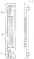
- Fig. 2 shows specifically some elements of the refrigerating device according to the invention;
- Fig. 3 shows schematically the electric circuit of the refrigerating device according to the invention;
- Fig. 4 shows specifically the display element of the refrigerating device according to the invention;
- Fig. 5 shows schematically a significant part of the control unit flowchart for the refrigerating device according to the invention;
- Fig. 6 shows schematically a further significant part of the control unit flowchart for the refrigerating device according to the invention.
- In figure 1, showing schematically the refrigerating circuit of the refrigerating device according to the present invention,
number 1 indicates a compressor to press the refrigerating fluid;number 2 indicates the delivery pipe exiting from thecompressor 1;number 3 indicates the condenser to cool the pressed fluid;number 4 indicates a three-way solenoid valve;number 5 indicates the capillary tube of theevaporator 6 for the compartment 9 used for the storage of fresh food (refrigerator);number 7 indicates the capillary tube of theevaporator 8 for the freezing compartment (freezer) 11;number 10 indicates a third intermediate compartment with variable temperature that can be used both for the storage of fresh food and for freezing purpose, as it will be better explained later. -
Number 12 indicates a fan for air circulation in thecompartments number 13 indicates the slots for air circulation in thecompartment 11,number 14 indicates a movable grid (flap) to close or open the relevant slots for air circulation adjustment inside theintermediate compartment 10. -
Number 15 indicates one of the two linear electromechanical actuators to move theflap 14 back and forward as it is better explained in Fig. 2. - In Fig. 2, where some elements of the refrigerating device according to the invention as specifically shown, the opposite actuator 15a is also shown along with the
flap 14 andactuator 15. - When
actuator 15 is enabled, it pushesflap 14 away from it; the same applies for actuator 15a. Obviously, if one actuator is operated the slots will be open to allow air circulation, whereas the slots will be closed and air circulation stopped when the other actuator is operated. - When the slots are open the temperature in the
compartment 10 will attain the same value as in compartment 11 (-18° condition), whereas when they are closed the temperature inside thecompartment 10 will rise up to a value close to the one of compartment 9 (+3°). - Operating both actuators suitably, the temperature inside the
compartment 10 can be maintained at a predetermined value selected between the above two values, as it will be better explained later. - It should be noted that both actuators are preferably used according to the ON-OFF principle,
i.e. flap 14 is either fully open or fully closed and the temperature setting is obtained by changing the opening and closing time. - Moreover, each actuator is only enabled for the time required to change the position of
flap 14; thus, activation time is greatly reduced while the actuator life is considerably extended. - In Fig. 3, showing schematically the electric circuit of the refrigerating device according to the invention, the central rectangle represents the electronic control card of the refrigerating device.
- Symbol uP indicates the microprocessor controlling the whole operation according to the flowchart schematically shown in Fig. 5.
- Symbol ID indicates the connecting interface from the microprocessor to the display/keyboard unit, as shown in Fig. 4.
- Symbol AD indicates an analogic/digital converter to convert into digital signals that can be processed by the microprocessor the analogic signals collected by the four relevant temperature probes S1, S2, S3, S4, related to the refrigerator compartment, refrigerator evaporator, intermediate compartment and freezer compartment, respectively.
- Specifically the microprocessor controls through the probe S3 that temperature in the
intermediate compartment 10 reaches and keeps the temperature input bykey 12 within the usual tolerance values (see Fig. 4). - Symbol ME indicates a non-volatile RAM memory (read and write memory), eg. of the EEPROM type (electronically erasable programmable read only memory). Said memory will be used to store the data should a current mains failure occur, eg. to let the alarm signal go on in case the max temperature admitted in the freezer compartment (-10°) be exceeded, also in case of a black-out.
- The memory is also suitably used to store the user's instructions in case of a black-out, which is specifically important for a refrigerating device as described above, as in such an event the configuration of the intermediate compartment could be lost if not stored in a non-volatile memory.
- Symbol IP indicates the power interface for actuators control. In fact, it is connected with:
- the flap closing actuator (CF)
- the flap opening actuator (AF)
- the flap heater (RF)
- the freezer heater (RR)
- the solenoid valve (EV, 4)
- the fan (EV, 12)
- the compressor (CO, 1).
- Symbol PS indicates the power supply connected to the mains through a transformer/voltage reducer TR and an interference filter FI, feeding all card circuits.
- Symbol FU indicates a fuse in series on the feed mains.
- Symbol LF indicates an illumination lamp for the refrigerator compartment, which can be switched off by a manual switch I4 or by the switch I3 on the refrigerator compartment door.
- Manual (mains) switch I4 is independent from the low voltage switch I1, which disables the refrigerator compartment. In fact,
switch 11 disables the control logic of the bypass solenoid valve of the refrigerating circuit (EV, 4), so that the refrigerating fluid will skip therefrigerator evaporator 6 and go to thefreezer evaporator 8 only. - This simple system allows switching off the refrigerator whenever the user wishes to do it, while only the freezer will be in operation.
- Since the light switch I4 in the refrigerator compartment is independent from the one (I1) used to switch off the refrigerator, it is possible either to switch off the light inside while the refrigerator is running or keep the light on, eg. for display purposes in a shop window, also while the refrigerator is disabled.
- Switch I2 on the freezer compartment door enables the alarm in case of open door (
element 27 of display, Fig. 4). - Symbol DS indicates the display/keyboard unit, as detailed in Fig. 4.
- Besides the illustration shown in Fig. 3, the microprocessor (uP) is also connected with a program memory (ROM), of the read only type, not shown in the figure.
- Said memory contains the operational instructions to the microprocessor; specifically, not only the microprocessor executes the functions described above in connection with the interfaces for control and handling as mentioned above, but it also provides for:
- intelligent defrost control, both in the freezer compartment (11) and in the refrigerator compartment (9), if not disabled, executing a defrost cycle each time the sum of the compressor operating times (1), for the compartment concerned, reaches a predetermined total time, eg. 10 hours; as for the freezer compartment, the time between two subsequent defrost cycles can be reduced if the compartment door is left open for quite a time; in the case of the refrigerator compartment, defrosting occurs anyway after a shorter time (eg. 6 hours) from the last defrost cycle, provided of course that the compartment has not been disabled in the meantime;
- activation of the alarm display (visual,
element 26 of display) and sound alarm (buzzer, not shown) if, for any reason, the temperature in the freezer compartment exceeds the max value admitted (-10°), while this event is stored at the same time in the non-volatile memory (ME), so that also in case of a mains failure and its subsequent restoration, the alarm remains enabled till the user will acknowledge it by pressing the erasing key T4; - handling a cooling timing (called "champagne function"), i.e. enabling, a timer for a max time of 95 minutes through the keys T6 and T7; if a different time from zero is input, the system will decrement it to zero; upon reaching this value the sound alarm will be enabled and the display start flashing till the user presses any key to inform the system that the elapsed time has been acknowledged;
- ensuring that both flap actuators (15 and 15a) cannot be enabled simultaneously, but only one at a time, to avoid damages caused by simultaneous actuation, as they have a contrasting action;
- activation of an automatic test program, comprising a fast enable sequence of all the loads and a real and true operation cycle lasting an adequate lapse of time to check correct operation, specifically of the second (11) and third (10) compartments; said fast sequence can be automatically enabled any time the refrigerating device is switched on, whereas the second part can obviously be enabled by qualified personnel only, either at the factory or for service purposes;
- execution of a test program in response to a proper simultaneous activation of control elements (eg. both pairs of keys T1, T2, T7, T8) to make field service easier, if required; during such a test program the display DS is used to release information on the tested operation, eg.
digits 32 can be used to show the temperatures measured by the probes S1 ... S4. - In Fig. 4, representing specifically the display of the refrigerating device according to the invention, the upper part of the figure shows all the luminescent elements of the display, which is of fluorescent type; the elements are 29 totally.
- The lower part of the figure shows eight control keys, indicated by symbols T1 to T8.
-
Number 21 indicates as a whole the three luminescent line elements that light alternatively one at a time by actuating the key T1 below. -
Number 22 indicates an element consisting of three digits and a symbol representing the refrigerating device with the first compartment (refrigerator) lighted. Said element, and likewise theelement 21, lights only if the refrigerator compartment is enabled (switch I1, Fig. 3). - By actuating key T1 the lines light up in the following sequence: line under nr. 6°, line under nr. 4°, line under nr. 2°, line under nr. 6°, and so on.
-
Number 23 indicates as a whole the three luminescent line elements that light up alternatively one at a time by actuating key T2 below. - The
number 24 indicates a three digit elements and a symbol representing the refrigerating device with the second compartment lighted. Said element, and likewiseelements 23, light up only if the third compartment is not configurated as a freezer. - By actuating key T2 the following elements will light up in sequence: line under nr. 3°, line under nr.0°, line under nr.-3°, line under nr. 3°, and so on.
- Number 25 indicates an element consisting of a symbol that represents the refrigerating device with the intermediate compartment lighted and digits -18°; this element will light up only if the intermediate compartment is configurated as a freezer by key T3 below.
- Configuration of the intermediate compartment as a freezer or as an intermediate temperature compartment can be achieved very simply through key T3. However, to prevent that said configuration may be changed either unwantedly, accidentally or by unauthorized people (eg. children), a protection is provided in the sense that when key T3 is pressed, the display element that was lit goes out and the other starts flashing. Key T3 must be kept pressed down for a predetermined number of flashes (eg. five) to attain acknowledgement of the configuration change otherwise the system goes back to its previous configuration.
- Moreover, when switching from the freezer configuration to the intermediate temperature configuration, the defrost heater (RF) of flap (14) is first enabled while the relevant actuator will be enabled after a certain time has elapsed (eg. some ten minutes).
- During the refrigerator configuration the heater RF is always ON.
-
Number 26 indicates an element representing a thermometer, which light up under temperature alarm conditions only, as mentioned above. - Simultaneously a buzzer (not shown) is enabled. The alarm goes out by pressing key T4 below.
-
Number 27 indicates an element that is intended to represent the freezer door. Said element lights up only when the freezer door has been left open. About 30 seconds later also the buzzer as mentioned above will be enabled. However, should one wish to keep the door open for a certain time, eg. to introduce lots of food inside, it is possible to exclude the buzzer. Since activation of the buzzer (which is anyway an intermittent function) due to an open door condition occurs less frequently than for a temperature alarm condition, the later alarm will produce a more intensive signal to draw the user's attention more than in the instance of an open door condition. -
Number 28 indicates an element representing the refrigerating device with the freezer compartment lighted. Said element remains always lighted. -
Number 29 indicates an element consisting of the writing SUPER. Said element will only light when the fast freezing condition is selected by the user by pressing the key T5 below. - Number 30 indicates an element consisting of the writing NORMAL. Said element will only light when the normal freezing condition is selected by the user by pressing the key T5 below.
- Number 31 indicates an element consisting of the word "min". Said element remains always lighted.
- Finally,
number 32 indicates an element consisting of two digits (by seven segments), representing the "champagne" function time as explained above, inputed by keys T6 and T7 being used to increase or decrease such time respectively. - Key T8 sets the luminescence of the display elements according to three different levels: minimum to medium, medium to maximum and maximum to minimum.
- In Fig. 5, showing schematically a significant portion (namely the one relating to the configuration change of intermediate compartment 10) of the flowchart for the control unit of the refrigerating device according to the invention,
number 39 indicates the start block of said flowchart. Said start, eg. in the specific instance, is the one that occurs when operating the refrigerating device for the first time; in fact, the system is set at the factory to start from said point, i.e. with the intermediate compartment configurated as a freezer. -
Block 39 transmits the control to thesubsequent block 40, which is a test block to verify that key T2 has been pressed. In the affirmative case (output SI), the control goes over to thesubsequent block 41; in the negative (output NO) the control returns to block 40. -
Block 41 is also a test block to verify that key T2 has been kept pressed at least 5 seconds. In the affirmative case (output SI), the control goes over to thesubsequent block 42; in the negative (output NO), the control returns to block 40. -
Block 42 handles the switch-over operation from a freezer configuration to a refrigerator configuration, providing for the following sequence of operations: - flap defrost heater RF is enabled
- 60 minutes' delay
- flap closes
- control goes over to the
subsequent block 43. -
Block 43 ensures thermostatic control of the intermediate compartment, i.e. it keeps the temperature value input by the opening/closing operations offlap 14. - Operation of
block 43 will be explained more in detail later dealing withblocks 47 to 52. -
Block 43 transmits the control to block 44, which is a test block to verify that key T3 has been pressed. In the affirmative case (output SI), the control goes to thesubsequent block 45; in the negative (output NO), the control returns to block 43. -
Block 45 is also a test block to verify that key T3 has been pressed at least for 5 seconds. In the affirmative case (output SI), the control goes over to thesubsequent block 46; in the negative (output NO), the control returns to block 43. -
Block 46 handles the switch-over operation from a refrigerator configuration to a freezer configuration, providing for the following sequence of operations: - flap defrost heater RF is disabled
- flap opens
- control is returned to block 40.
-
Block 47 is a test block to verify that the temperature detected by the probe S3 in the intermediate compartment is lower than the one input bykey 2. In the affermative case (output SI), the control goes over to thesubsequent block 48; in the negative (output NO), the control returns to block 47. -
Block 48 is also a test block to verify thatflap 14 opening actuator has been disenergized at least for 60 seconds. In the affirmative case (output SI), the control goes over to thesubsequent block 49; in the negative (output NO), the control returns to block 48. -
Block 49 enables theflap 14 closing actuator and maintains it energized for a predetermined time to ensure it is actually closed. -
Block 49 will then transmit the control to thesubsequent block 50, which is a test block to verify that the temperature detected by probe S3 in the intermediate compartment is higher than the value input bykey 2. In the affirmative case (output SI), the control goes over to thesubsequent block 51; in the negative (output NO), the control returns to block 50. -
Block 51 is also a test block to verify that theflap 14 closing actuator has been disenergized at least for 60 seconds. In the affirmative case (output SI), the control goes over to thesubsequent block 52; in the negative (output NO), the control returns to block 51. -
Block 52 enables theflap 14 opening actuator and maintains it energized for a predetermined time to ensure it is actually open. - Then block 52 return the control to block 47.
- In Fig. 6, representing schematically a further significant portion of the control system flowchart of the refrigerating device according to the invention, the left side indicates the defrost control of the
freezer compartment 11, whereas the right side refers to the time-controlled cooling function. -
Block 59 represents the function start block and the control fromblock 59 is transmitted to thesubsequent block 60. -
Block 60 is a test block to verify that the compressor is enabled. In the affirmative case (output SI), the control goes over to thesubsequent block 61; in the negative (output NO), the control returns to block 60. -
Block 61 is also a test block to verify if the freezer door is open. - In the affirmative case (output SI), the control goes over to block 63; in the negative (output NO), the control goes over to block 62.
-
Block 62 increases by one unit the time storage counter of active compressor (CONT=CONT+1).Block 63 increases by two units the time storage counter of active compressor (CONT=CONT+2). - Both the
block 62 and block 63 transmit the control to thesubsequent block 64, which is a test block to verify that the counter above (CONT) shows a time over 10 hours. In the affirmative case (output SI), the control goes over to thesubsequent block 65; in the negative (output NO), the control returns to block 60. -
Block 65 is a test block to verify that the compressor has been active at least for three hours. In the affirmative case (output SI), the control goes over to block 67; in the negative (output NO), the control goes over to block 66. -
Block 66 is also a test block to verify that the compressor is out. In the affirmative case (output SI), the control goes over to block 68; in the negative (output NO), the control returns to block 65. -
Block 67 provides for the forced cutout of the compressor, then it transmit the control to thesubsequent block 68.Block 68 provides for the defrosting of thefreezer compartment 11, then the control is transmitted to thesubsequent block 69. -
Block 69 resets the counter (CONT=0), then the control is returned to block 60. - Let us now consider the handling of the time-controlled cooling function.
-
Block 70 represents the function start block; block 70 transmits the control to thesubsequent block 71. -
Block 71 is a test block to verify that the time (T) input by keys T6-T7 is equal or 5 minutes higer. In the affirmative case (output SI), the control goes over to thesubsequent block 72; in the negative (output NO), the control returns to block 71. -
Block 72 decrease the time by one second (T=T-1), then the control goes over tosubsequent block 73. -
Block 73 is a test block to verify that the time is equal to zero (T=0?). In the affirmative case (output SI), the control goes over to thesubsequent block 74; in the negative (output NO), the control returns to block 72. -
Block 74 is also a test block to verify that the time has been manually reset. In the affirmative case (output SI), the control returns to block 71; in the negative (output NO), the control goes over to thesubsequent block 75. -
Block 75 enables the visual display (flashing of digits 32) and sound alarm (buzzer) signalling the exceeded time, then the control goes over to thesubsequent block 76. -
Block 76 is a test block to verify that any key whatever has been pressed. In the affirmative case (output SI), the control returns to block 71; in the negative (output NO) the control returns to block 75. - The advantages of the refrigerating device according to the present invention are clear.
- Specifically, they are represented by the following features:
- Availability of a third compartment for food preservation, which can be configurated at will either as an extra freezer or an extra refrigerator compartment (by setting it on +3°), or still as a compartment for temporary preservation of perishable food, eg. fresh meat (by setting it on -3°);
- Easy and comfortable control through its clear display and relevant keyboard;
- Low-cost thanks to its simple air regulating system (only one flap and two linear actuators);
- Operating safety through the incorporated protecting devices;
- Easy testing and service procedures through the programs contained in the ROM memory associated with the microprocessor.
- The use of only one actuator of the push-pull type instead of the two actuators (15, 15a) is possible, whose loose element will be suitably hooked onto
flap 14. - Said sole actuator can always operate according to the ON-OFF system or according to a proportional system.
Claims (30)
- Refrigerating device comprising three compartments (9, 10, 11), among which a first compartment (9) used for the storage of fresh food and a second compartment (11) used for the freezing and storage of food, a refrigerating circuit comprising a compressor (1), a condenser (3), first and second evaporators (6,8), arranged in said first and said second compartments (9,11) respectively, coupled to the refrigerating circuit through an electrovalve (4), and control means allowing the user to set the third compartment (10) either for the storage of fresh food or for its freezing, characterized in that it further comprises a fan (12) and slots for air circulation in the second and third compartments (10,11) and in that said control means comprise a central electronic unit including in particular a microprocessor (µP) which, in response to the activation by the user of a specific control element (T2, T3), can control said compressor (1), the electrovalve (4) and further electromechanical actuating means (14, 15, 15a) which comprise at least one actuator (15, 15a) enabled to move a flap (14) to close or open the relevant slots for air circulation adjustment inside the third compartment (10).
- Refrigerating device according to claim 1, characterized in that electronic protection means (µP, 41, 45) are provided to prevent an accidental change of the use of the said third comparment (10).
- Refrigerating device according to claim 1, characterized in that said specific control element comprises a key (T2, T3), in particular being part of a keyboard/display unit (Fig. 4) of easy access for the user.
- Refrigerating device according to claim 1, characterized in that said central electronic unit is associated with the specific control element (T2) to achieve temperature selection among various different values in said third compartment (10).
- Refrigerating device according to claim 1, characterized in that means (S3, uP, 43) are provided to maintain the temperature substantially at a predetermined value in said third compartment (10).
- Refrigerating device according to claims 4 and 5, characterized in that means (T2, S3, µP, 43) are provided to set and maintain said temperature at a preferred value selected within a predetermined range of values (+3°, -3°).
- Refrigerating device according to claim 1, characterized in that said at least one actuator (15, 15a), which is of the linear type, is enabled to move said flap (14) for air circulation adjustment through an ON-OFF system or a proportional system.
- Refrigerating device according to claim 7, characterized in that said further electromechanical actuating means (14, 15, 15a) comprise two linear actuators (15, 15a) which are enabled alternatively to move said flap (14) for air circulation adjustment.
- Refrigerating device according to claim 8, characterized in that electronic protection means (µP, 48, 51) are provided to avoid that both actuators (15, 15a) may be simultaneously enabled.
- Refrigerating device according to claim 1, characterized in that heating means (RF) are provided to defrost said flap (14) and that said heating means (RF) are always energized for a time interval before said at least one actuator (15, 15a) is enabled.
- Refrigerating device according to claim 1, characterized in that said at least one actuator (15, 15a) is of the push-pull type.
- Refrigerating device according to claim 1, characterized in that display means (DS) associated with control elements (T1 ... T8) are provided to make user's control of the refrigerating device easier.
- Refrigerating device according to claim 12, characterized in that the luminescence of said display (DS) can be adjusted by means of one of said control elements (T8).
- Refrigerating device according to claim 12, characterized in that said control elements comprise a number of keys (T1 ... T8).
- Refrigerating device according to claim 1, characterized in that display means (DS) of fluorescent type are provided, which comprise a number of either numerical and/or graphical luminescent elements (21 ... 32), to be enabled either individually or in common.
- Refrigerating device according to claim 1, characterized in that said central electronic unit comprises defrost handling means (60 ... 69) both for said first compartment (9) and said second compartment (11), in such a way that a defrost cycle is executed each time the sum of the compressor (1) active times relating to the compartment concerned reaches a predetermined total value.
- Refrigerating device according to claim 16, characterized in that said central electronic unit comprises some means for the handling of defrost cycles for said first compartment (9) in such a way that a defrost cycle of said first compartment (9) is anyway executed after a predetermined time has elapsed since the last defrost cycle, and provided that operation of said compartment (9) is not disabled in the meantime.
- Refrigerating device according to claim 16, characterized in that said central electronic unit comprises some means (60 ... 69) to handle the defrost cycles of said second compartment (11) in such a way that the time elapsing between two subsequent defrost cycles is reduced if the compartment (11) door has been left open for some time.
- Refrigerating device according to claim 1, characterized in that said central electronic unit is associated with non-volatile memory means (ME) into which operative data are stored, specifically referring to the selected modes, such as the configuration of the third compartment (10), in order that should there be a mains failure, such data are stored to allow resuming regular operation when the mains supply is restored.
- Refrigerating device according to claim 19, characterized in that said central electronic unit associated with non-volatile memory means (ME) enables an alarm signal (26) when the temperature in said second compartment (11) exceeds a predetermined value, and that, even if the temperature in said second compartment (11) decreases again below said predetermined value, said alarm signal (26) remains enabled though in the meantime the mains supply has failed and has been restored again.
- Refrigerating device according to claim 1, characterized in that it comprises some pre-settable timing means (32), which can be enabled by means of control elements (T6, T7) and capable of signalling that the preset time interval has elapsed.
- Refrigerating device according to claim 1, characterized in that said central electronic unit comprise some means to execute an automatic test program, comprising a fast enable sequence of all loads and/or a real and true operation cycle of suitable length to check the correct operation specifically of the second and third compartments (10, 11).
- Refrigerating device according to claim 12, characterized in that said central electronic unit comprises some means for executing a test program in response to a suitable simultaneous activation of some (T1, T2, T7, T8) of the control elements (T1, T2, ..., T8).
- Refrigerating device according to claim 23, characterized in that during said test program said display (DS) is used for signalling information data relating to the tested operation; specifically, to indicate the temperatures measured by relevant probes (S1 .. S4).
- Refrigerating device according to claim 1, characterized in that said electrovalve (4) provides for the exclusion, after enabling a control (I1), of said first compartment (9) from the refrigerating circuit.
- Refrigerating device according to claim 25, characterized in that said electrovalve (4) is represented by an electric low-voltage switch (I1).
- Refrigerating device according to claim 1, characterized in that some visual (27) and sound alarm means are provided to inform that the door of the second compartment remains open for a time exceeding a predetermined period.
- Refrigerating device according to claim 27, characterized in that said sound alarm means can be switched off.
- Refrigerating device according to claims 20 and 27, characterized in that said alarm signal (26) produces a more intensive signal than the one of said visual (27) and sound alarm.
- Refrigerating device according to claim 25, characterized in that some illumination means (LF) are provided in said first compartment (9) and that manual disable means (I4) for said illumination means (LF) are foreseen independently from said control (I1).
Applications Claiming Priority (2)
| Application Number | Priority Date | Filing Date | Title |
|---|---|---|---|
| IT6707689 | 1989-02-13 | ||
| IT8967076A IT1232574B (en) | 1989-02-13 | 1989-02-13 | REFRIGERATED REFRIGERATOR |
Publications (3)
| Publication Number | Publication Date |
|---|---|
| EP0383222A2 EP0383222A2 (en) | 1990-08-22 |
| EP0383222A3 EP0383222A3 (en) | 1991-03-20 |
| EP0383222B1 true EP0383222B1 (en) | 1994-12-07 |
Family
ID=11299377
Family Applications (1)
| Application Number | Title | Priority Date | Filing Date |
|---|---|---|---|
| EP90102678A Expired - Lifetime EP0383222B1 (en) | 1989-02-13 | 1990-02-12 | Refrigerating device |
Country Status (4)
| Country | Link |
|---|---|
| EP (1) | EP0383222B1 (en) |
| DE (1) | DE69014673T2 (en) |
| ES (1) | ES2066019T3 (en) |
| IT (1) | IT1232574B (en) |
Families Citing this family (11)
| Publication number | Priority date | Publication date | Assignee | Title |
|---|---|---|---|---|
| IT1248098B (en) * | 1991-04-18 | 1995-01-05 | Merloni Elettrodomestici Spa | ELECTRONICALLY CONTROLLED HOUSEHOLD APPLIANCE, IN PARTICULAR A REFRIGERATOR |
| IT1245076B (en) * | 1991-04-18 | 1994-09-13 | Merloni Elettrodomestici Spa | FRIDGE |
| US5363669A (en) * | 1992-11-18 | 1994-11-15 | Whirlpool Corporation | Defrost cycle controller |
| IT1289491B1 (en) * | 1996-12-20 | 1998-10-15 | Whirpool Europ S R L | TEMPERATURE CONTROL DEVICE OF A COMPARTMENT AT CONTROLLED TEMPERATURE LOWER OR SUBSTANTIALLY EQUAL TO 0 ° C RECEIVED WITHIN |
| DE102004014926A1 (en) | 2004-03-26 | 2005-10-13 | BSH Bosch und Siemens Hausgeräte GmbH | Refrigerating appliance with two storage compartments |
| ITTO20060110U1 (en) * | 2006-07-24 | 2008-01-25 | Indesit Co Spa | REFRIGERATION APPLIANCE WITH COOLING FUNCTIONS FOODS FOR PRE-SET TIMES |
| CN103047829A (en) * | 2011-10-14 | 2013-04-17 | 博西华电器(江苏)有限公司 | Refrigeration device and working method thereof |
| US11346591B2 (en) | 2018-03-02 | 2022-05-31 | Electrolux Do Brasil S.A. | Single air passageway and damper assembly in a variable climate zone compartment |
| US11512888B2 (en) | 2018-03-02 | 2022-11-29 | Electrolux Do Brasil S.A. | Air passageways in a variable climate zone compartment |
| AU2018411065B2 (en) | 2018-03-02 | 2024-11-07 | Electrolux Do Brasil S.A. | Heater in a variable climate zone compartment |
| PL3903049T3 (en) * | 2018-12-25 | 2024-01-03 | Arçelik Anonim Sirketi | A cooling device with reduced energy consumption |
Family Cites Families (5)
| Publication number | Priority date | Publication date | Assignee | Title |
|---|---|---|---|---|
| US3411312A (en) * | 1967-09-01 | 1968-11-19 | Whirlpool Co | Refrigerator with convertible compartment |
| DE8403581U1 (en) * | 1984-02-07 | 1988-01-07 | Bosch-Siemens Hausgeraete Gmbh, 7000 Stuttgart | Electrical household appliance |
| CA1228139A (en) * | 1984-03-06 | 1987-10-13 | John Polkinghorne | Appliance control system |
| FR2576676B1 (en) * | 1985-01-29 | 1987-02-27 | Selnor | THREE-COMPARTMENT REFRIGERATOR CABINET |
| US4682474A (en) * | 1986-07-28 | 1987-07-28 | Whirlpool Corporation | Temperature responsive baffle control circuit for a refrigerator |
-
1989
- 1989-02-13 IT IT8967076A patent/IT1232574B/en active
-
1990
- 1990-02-12 DE DE69014673T patent/DE69014673T2/en not_active Expired - Fee Related
- 1990-02-12 EP EP90102678A patent/EP0383222B1/en not_active Expired - Lifetime
- 1990-02-12 ES ES90102678T patent/ES2066019T3/en not_active Expired - Lifetime
Also Published As
| Publication number | Publication date |
|---|---|
| EP0383222A3 (en) | 1991-03-20 |
| DE69014673T2 (en) | 1995-05-24 |
| DE69014673D1 (en) | 1995-01-19 |
| IT1232574B (en) | 1992-02-26 |
| ES2066019T3 (en) | 1995-03-01 |
| IT8967076A0 (en) | 1989-02-13 |
| EP0383222A2 (en) | 1990-08-22 |
Similar Documents
| Publication | Publication Date | Title |
|---|---|---|
| US4297852A (en) | Refrigerator defrost control with control of time interval between defrost cycles | |
| US4843833A (en) | Appliance control system | |
| US5634346A (en) | Apparatus and method for controlling a room air conditioner | |
| US4439998A (en) | Apparatus and method of controlling air temperature of a two-evaporator refrigeration system | |
| US4283921A (en) | Control and alarm system for freezer case temperature | |
| US4173871A (en) | Refrigeration apparatus demand defrost control system and method | |
| EP0383222A2 (en) | Refrigerating device | |
| JPS62206370A (en) | Refrigeration control system capable of self-adjusting interval of defrostation | |
| GB2144838A (en) | Refrigerators | |
| EP0686818B1 (en) | Control method for a refrigerator apparatus and an apparatus implementing such method | |
| JPS5915782A (en) | Temperature controller for refrigerator | |
| US3922874A (en) | Evaporator fan delay circuit | |
| EP0513539B1 (en) | Household appliance with electronic control | |
| GB2083928A (en) | Apparatus and Method of Controlling Temperature of a Two Evaporator Refrigeration System | |
| KR100191533B1 (en) | Defrost control method of refrigerator | |
| US4959968A (en) | Method for controlling the defrosting of refrigerator-freezer units of varying degrees of frost accumulation | |
| EP0392521B1 (en) | Refrigerating device and method for controlling its operation | |
| JP4945496B2 (en) | refrigerator | |
| US3483919A (en) | Electric refrigerator with defrosting means | |
| JPH03158679A (en) | Cooling controller | |
| EP0388726B1 (en) | Refrigerating appliance with single thermostatic temperature control device | |
| EP0298347A2 (en) | Refrigerator with rapid-cooling feature | |
| JP4142182B2 (en) | Temperature control device | |
| JP3469607B2 (en) | Dryer | |
| EP0995957A2 (en) | Refrigeration apparatus with temperature balancing device |
Legal Events
| Date | Code | Title | Description |
|---|---|---|---|
| PUAI | Public reference made under article 153(3) epc to a published international application that has entered the european phase |
Free format text: ORIGINAL CODE: 0009012 |
|
| AK | Designated contracting states |
Kind code of ref document: A2 Designated state(s): DE ES FR GB |
|
| PUAL | Search report despatched |
Free format text: ORIGINAL CODE: 0009013 |
|
| AK | Designated contracting states |
Kind code of ref document: A3 Designated state(s): DE ES FR GB |
|
| 17P | Request for examination filed |
Effective date: 19910918 |
|
| 17Q | First examination report despatched |
Effective date: 19920727 |
|
| GRAA | (expected) grant |
Free format text: ORIGINAL CODE: 0009210 |
|
| AK | Designated contracting states |
Kind code of ref document: B1 Designated state(s): DE ES FR GB |
|
| REF | Corresponds to: |
Ref document number: 69014673 Country of ref document: DE Date of ref document: 19950119 |
|
| REG | Reference to a national code |
Ref country code: ES Ref legal event code: FG2A Ref document number: 2066019 Country of ref document: ES Kind code of ref document: T3 |
|
| ET | Fr: translation filed | ||
| PLBE | No opposition filed within time limit |
Free format text: ORIGINAL CODE: 0009261 |
|
| STAA | Information on the status of an ep patent application or granted ep patent |
Free format text: STATUS: NO OPPOSITION FILED WITHIN TIME LIMIT |
|
| 26N | No opposition filed | ||
| REG | Reference to a national code |
Ref country code: GB Ref legal event code: IF02 |
|
| PGFP | Annual fee paid to national office [announced via postgrant information from national office to epo] |
Ref country code: ES Payment date: 20080225 Year of fee payment: 19 |
|
| PGFP | Annual fee paid to national office [announced via postgrant information from national office to epo] |
Ref country code: DE Payment date: 20080310 Year of fee payment: 19 Ref country code: GB Payment date: 20080219 Year of fee payment: 19 |
|
| PGFP | Annual fee paid to national office [announced via postgrant information from national office to epo] |
Ref country code: FR Payment date: 20080215 Year of fee payment: 19 |
|
| GBPC | Gb: european patent ceased through non-payment of renewal fee |
Effective date: 20090212 |
|
| REG | Reference to a national code |
Ref country code: FR Ref legal event code: ST Effective date: 20091030 |
|
| PG25 | Lapsed in a contracting state [announced via postgrant information from national office to epo] |
Ref country code: DE Free format text: LAPSE BECAUSE OF NON-PAYMENT OF DUE FEES Effective date: 20090901 |
|
| REG | Reference to a national code |
Ref country code: ES Ref legal event code: FD2A Effective date: 20090213 |
|
| PG25 | Lapsed in a contracting state [announced via postgrant information from national office to epo] |
Ref country code: GB Free format text: LAPSE BECAUSE OF NON-PAYMENT OF DUE FEES Effective date: 20090212 Ref country code: FR Free format text: LAPSE BECAUSE OF NON-PAYMENT OF DUE FEES Effective date: 20090302 |
|
| PG25 | Lapsed in a contracting state [announced via postgrant information from national office to epo] |
Ref country code: ES Free format text: LAPSE BECAUSE OF NON-PAYMENT OF DUE FEES Effective date: 20090213 |