EP0382907B1 - Capacitive discharge ignition exciter using SCR discharge switches - Google Patents
Capacitive discharge ignition exciter using SCR discharge switches Download PDFInfo
- Publication number
- EP0382907B1 EP0382907B1 EP89121809A EP89121809A EP0382907B1 EP 0382907 B1 EP0382907 B1 EP 0382907B1 EP 89121809 A EP89121809 A EP 89121809A EP 89121809 A EP89121809 A EP 89121809A EP 0382907 B1 EP0382907 B1 EP 0382907B1
- Authority
- EP
- European Patent Office
- Prior art keywords
- scrs
- conditioning circuit
- ignition system
- secondary windings
- storage capacitor
- Prior art date
- Legal status (The legal status is an assumption and is not a legal conclusion. Google has not performed a legal analysis and makes no representation as to the accuracy of the status listed.)
- Expired - Lifetime
Links
- 239000003990 capacitor Substances 0.000 claims description 40
- 230000003750 conditioning effect Effects 0.000 claims description 32
- 238000004804 winding Methods 0.000 claims description 30
- 230000001681 protective effect Effects 0.000 claims description 6
- 230000000737 periodic effect Effects 0.000 claims description 3
- 239000004065 semiconductor Substances 0.000 claims description 2
- 238000013016 damping Methods 0.000 claims 2
- 230000010355 oscillation Effects 0.000 claims 1
- 239000007789 gas Substances 0.000 description 9
- 238000002485 combustion reaction Methods 0.000 description 6
- 230000002441 reversible effect Effects 0.000 description 4
- XUIMIQQOPSSXEZ-UHFFFAOYSA-N Silicon Chemical compound [Si] XUIMIQQOPSSXEZ-UHFFFAOYSA-N 0.000 description 2
- 238000010586 diagram Methods 0.000 description 2
- 239000002245 particle Substances 0.000 description 2
- 229910052710 silicon Inorganic materials 0.000 description 2
- 239000010703 silicon Substances 0.000 description 2
- 230000003321 amplification Effects 0.000 description 1
- 230000001419 dependent effect Effects 0.000 description 1
- 238000007599 discharging Methods 0.000 description 1
- 238000009760 electrical discharge machining Methods 0.000 description 1
- 239000000446 fuel Substances 0.000 description 1
- 238000004519 manufacturing process Methods 0.000 description 1
- 239000000463 material Substances 0.000 description 1
- 238000000034 method Methods 0.000 description 1
- 239000000203 mixture Substances 0.000 description 1
- 238000003199 nucleic acid amplification method Methods 0.000 description 1
- 230000002285 radioactive effect Effects 0.000 description 1
- 230000001105 regulatory effect Effects 0.000 description 1
- 230000000630 rising effect Effects 0.000 description 1
Images
Classifications
-
- F—MECHANICAL ENGINEERING; LIGHTING; HEATING; WEAPONS; BLASTING
- F02—COMBUSTION ENGINES; HOT-GAS OR COMBUSTION-PRODUCT ENGINE PLANTS
- F02P—IGNITION, OTHER THAN COMPRESSION IGNITION, FOR INTERNAL-COMBUSTION ENGINES; TESTING OF IGNITION TIMING IN COMPRESSION-IGNITION ENGINES
- F02P3/00—Other installations
- F02P3/06—Other installations having capacitive energy storage
- F02P3/08—Layout of circuits
- F02P3/0807—Closing the discharge circuit of the storage capacitor with electronic switching means
- F02P3/0838—Closing the discharge circuit of the storage capacitor with electronic switching means with semiconductor devices
-
- F—MECHANICAL ENGINEERING; LIGHTING; HEATING; WEAPONS; BLASTING
- F02—COMBUSTION ENGINES; HOT-GAS OR COMBUSTION-PRODUCT ENGINE PLANTS
- F02C—GAS-TURBINE PLANTS; AIR INTAKES FOR JET-PROPULSION PLANTS; CONTROLLING FUEL SUPPLY IN AIR-BREATHING JET-PROPULSION PLANTS
- F02C7/00—Features, components parts, details or accessories, not provided for in, or of interest apart form groups F02C1/00 - F02C6/00; Air intakes for jet-propulsion plants
- F02C7/26—Starting; Ignition
-
- F—MECHANICAL ENGINEERING; LIGHTING; HEATING; WEAPONS; BLASTING
- F02—COMBUSTION ENGINES; HOT-GAS OR COMBUSTION-PRODUCT ENGINE PLANTS
- F02P—IGNITION, OTHER THAN COMPRESSION IGNITION, FOR INTERNAL-COMBUSTION ENGINES; TESTING OF IGNITION TIMING IN COMPRESSION-IGNITION ENGINES
- F02P15/00—Electric spark ignition having characteristics not provided for in, or of interest apart from, groups F02P1/00 - F02P13/00 and combined with layout of ignition circuits
- F02P15/001—Ignition installations adapted to specific engine types
- F02P15/003—Layout of ignition circuits for gas turbine plants
-
- F—MECHANICAL ENGINEERING; LIGHTING; HEATING; WEAPONS; BLASTING
- F02—COMBUSTION ENGINES; HOT-GAS OR COMBUSTION-PRODUCT ENGINE PLANTS
- F02P—IGNITION, OTHER THAN COMPRESSION IGNITION, FOR INTERNAL-COMBUSTION ENGINES; TESTING OF IGNITION TIMING IN COMPRESSION-IGNITION ENGINES
- F02P7/00—Arrangements of distributors, circuit-makers or -breakers, e.g. of distributor and circuit-breaker combinations or pick-up devices
- F02P7/02—Arrangements of distributors, circuit-makers or -breakers, e.g. of distributor and circuit-breaker combinations or pick-up devices of distributors
- F02P7/03—Arrangements of distributors, circuit-makers or -breakers, e.g. of distributor and circuit-breaker combinations or pick-up devices of distributors with electrical means
- F02P7/035—Arrangements of distributors, circuit-makers or -breakers, e.g. of distributor and circuit-breaker combinations or pick-up devices of distributors with electrical means without mechanical switching means
-
- F—MECHANICAL ENGINEERING; LIGHTING; HEATING; WEAPONS; BLASTING
- F02—COMBUSTION ENGINES; HOT-GAS OR COMBUSTION-PRODUCT ENGINE PLANTS
- F02B—INTERNAL-COMBUSTION PISTON ENGINES; COMBUSTION ENGINES IN GENERAL
- F02B1/00—Engines characterised by fuel-air mixture compression
- F02B1/02—Engines characterised by fuel-air mixture compression with positive ignition
- F02B1/04—Engines characterised by fuel-air mixture compression with positive ignition with fuel-air mixture admission into cylinder
Definitions
- the present invention relates to a gas turbine engine ignition system. More particularly, it relates to an ignition exciter circuit which includes a high voltage storage capacitor and s ilicon c ontrolled r ectifiers (SCR) serving as a switch to connect the storage capacitor to the input of a conditioning circuit supplying high voltage, high energy pulses to an igniter plug located in the combustion chamber of a gas turbine engine.
- SCR s ilicon c ontrolled r ectifiers
- Capacitive discharge ignition exciter circuits in wide spread use for gas turbine engines are of the types of variations of the types described in U.S. Patent US-A-3 619 638 "Pulse Generating Apparatus” by E. M. Phinney, issued November 9, 1971 and in U.S. Patent US-A-3 531 738 "Continuous Duty Ignition System” by K. H. Thakore, issued September 29, 1970.
- a control spark gap not to be confused with the igniter plug spark gap, is used to initiate discharge of a storage capacitor into a conditioning circuit which transforms the discharge current from the storage capacitor in a high voltage, high energy pulse for supply to the engine igniter plug.
- the engine igniter plug is analogous to the spark plug of an Otto cycle engine in that is functions to provide a spark discharge to initiate combustion of the fuel mixture in the engine combustion chamber.
- Ignition systems for turbine engine ignition systems supply spark continuously to the engine instead of supplying spark in timed relationship to the engine cycle and in that the energy and instantaneous power requirements for a turbine engine system are much higher than those of an Otto cycle engine system.
- the lack of a requirement to supply timed spark in a turbine ignition system leads to certain simplifications in the exciter circuit, among which is the use of a control spark gap to initiate discharge of the storage capacitor.
- the control spark gap normally comprises a pair of substantial electrodes enclosed in a gas tight housing together with some type of radioactive emitter of beta particles. The beta particles ionize the gas within the housing to promote discharge through the gap at more uniform voltage levels.
- Control spark gaps create service problems in turbine ignition systems. Spark erosion of the electrodes necessitates more frequent replacement of the spark gaps than is desirable and the radioactivity of material used in the gaps demands that special procedures be used in the manufacture, storage, handling and disposition of the gaps. For these reasons, consideration has been given in the past to replacement of the control spark gap with an alternative form of switching device, such as a silicon controlled rectifier (SCR).
- SCR silicon controlled rectifier
- SCRs have been used as capacitor switching devices in prior capacitive discharge ignition systems designed for use in Otto cycle engines.
- Two examples of such ignition systems are seen in U.S. Patent US-A-4 232 646 for "Ignition System for Internal Combustion Engines with a Magneto Generator", issued November 11, 1980 and in U.S. Patent US-A-3 605 714 for "contactless Ignition System", issued September 20, 1971.
- a single SCR is connected in series with the storage capacitor and the primary of an ignition transformer. At the appropriate time in the engine cycle a trigger pulse is applied to the gate electrode of the SCR, switching it into conduction and discharging the storage capacitor through the ignition transformer to generate an engine spark.
- the Otto cycle engine circuits use low voltage SCRs to switch the low voltage side of an ignition coil to develop a current limited, low instantaneous power, high voltage pulse for the spark plug. Such circuits were not designed for, nor can they deliver the required instantaneous power to fire a turbine engine igniter plug effectively.
- the invention comprises an exciter circuit for a gas turbine engine ignition system in which a storage capacitor is charged continuously from a source of high voltage d.c.
- Two or more SCRs are connected in series between the terminal of the storage capacitor connected to the high voltage d.c. source and one terminal of a high voltage conditioning circuit. The remaining terminals of the storage capacitor and the conditioning circuit are returned to the high voltage source through ground.
- a protective network is connected in ladder fashion across the SCRs to distribute the charge voltage of the storage capacitor equally across the SCRs when the latter are nonconductive.
- a pulse generator supplies periodic triggering pulses simultaneously to the SCRs to render the SCRs simultaneously conductive and thereby rapidly discharge the storage capacitor through the conditioning circuit.
- the output of the conditioning circuit is connected to an igniter plug located in the engine combustion chamber to provide ignition spark. If one or more, but less than all, of the SCRs should fail by short circuit, the remaining unaffected SCRs continue to operate to interrupt discharge current from the storage capacitor and thereby provide high energy, rapidly rising current impulses to the conditioning circuit.
- a high voltage d.c. power supply 10 receives 115 V., 400Hz a.c. input and converts the same into high voltage d.c., preferrably 4 kV. d.c.
- a storage capacitor 11 connected between the positive output terminal of supply 10 and ground receives continuous charging current from supply 10 until charged to 4kV. Capacitor 11 may suitably have a value of 1 ⁇ F (mfd).
- the positively charged terminal of capacitor 11 is connected through a commutating inductor 12 to the anode of a first SCR 14.
- the cathode of SCR 14 is connected to the anode of a second SCR 15, the cathode of which is connected to the anode of a third SCR 16.
- a protective network comprised of three identical, series connected sections 17, 18 and 19 extends in parallel with the series connected SCRs 14 - 16.
- Each of the network sections 17-19 comprises an inductor 21, a resistor 23 connected in parallel with a capacitor 23 with the upper node of the parallel combination connected in series with resistor 21 and with the lower node of the combination connected in series with a second resistor 24.
- the upper end 25 of network section 17 is connected to the anode of SCR 14.
- the lower end 26 of network section 17, which is also the upper end of network section 18, is connected to the line interconnecting the cathode of SCR 14 and the anode of SCR 15.
- the lower end of section 18 - upper end 27 of section 19 is connected to the line interconnecting the cathode of SCR 15 and the anode of SCR 16.
- the cathode of SCR 16 is connected to one input terminal 30 of the conditioning circuit 31.
- the other input terminal 32 of conditioning circuit 31 is grounded.
- Conditioning circuit 31 functions to reshape the substantially rectangular waveform of the discharge current from storage capacitor 11 to insert at the leading edge thereof an extra high voltage, very short duration spike. The reshaped waveform promotes ionization of the gases surrounding the engine igniter plug and improves the efficiency of the spark discharge through the igniter plug.
- Terminal 30 is connected to one end of the primary winding of a transformer 33.
- the other end of the primary wiring is grounded through a capacitor 49.
- One end of the secondary winding of transformer 33 is connected to the input end of the primary winding thereof and the opposite end of the secondary winding is connected through output terminal 34 to one electrode of an igniter plug 48 located in the engine combustion chamber.
- the other electrode of igniter plug 48 is grounded.
- the cathode of a diode 50 is connected to the input end of the primary of transformer 33.
- the anode of diode 50 is grounded. Diode 50 damps the negative voltage induced at the input end of the primary of transformer 33 when the discharge pulse from storage capacitor 11 ends, preventing damage to the SCRs and improving the efficiency of the conditioning circuit.
- a pulse transformer 35 having a single primary winding 36 and three secondary windings 37 - 39 supplies simultaneous trigger impulses to the gates of SCRs 14 - 16 when a trigger pulse is applied to primary winding 36.
- Trigger pulses are generated by a commercially available integrated circuit IC-1, suitably type NE 555, a product of National Semiconductor Corp., Santa Clara, California.
- IC-1 is adjusted to generate negative-going pulses on line 40 at a rate of from 2-4 p.p.s.
- the pulses on line 40 are fed to the base of a driver transistor 41 for amplification prior to application to input winding 36 of pulse transformer 35.
- Transistor 41 is protected against the application of overvoltage by a spark gap 42 and against the application of reverse currents by a resistor 43 - diode 44 combination connected from the collector of transistor 41 to ground.
- the secondary windings 37-39 of pulse transformer 35 are respectively connected between the gate and cathode electrodes of SCRs 14-16 and are phased with respect to primary winding 36 to generate a positive-going pulse at the SCR gates when a trigger pulse is applied to primary 36.
- the positive pulses on the gates of the SCRs switch them into conduction simultaneously to rapidly discharge the charge on capacitor 11 through the conditioning circuit 31 and generate an ignition spark at igniter plug 33.
- the reverse voltages induced in inductor 12 and the inductors 21 of network sections 17-19 momentarily reverse bias SCRs 14-16 and render them again nonconductive until the appearance of the next trigger pulse.
- Diodes 46 and 47 connected in each of the circuits of secondary windings 37-39 protect against the application of reverse currents to the gates of the respective SCRs.
- IC-1 and transistor 41 receive input power at +15 V. from a 15 V.d.c. regulated supply powered by the 115 V.a.c source.
- resistors 22 and 24 in the series connected network sections form a voltage divider which divides the voltage of the charge stored on capacitor 11 equally across SCRs 14-16 when the SCRs are nonconductive.
- Capacitors 23 provide protection against the appearance of excessive voltage across any of the SCRs 14-16 which may be slow in switching.
- Inductors 21 and resistor 22 provide di/dt and current limiting when capacitors C23 discharge.
- each of the SCRs is stressed only to the extent of one-third of the total charge voltage of capacitor 11. Moreover, should one or more, but less than all, of the SCRs 14-16 fail by short circuit, the remaining unaffected SCR will still function to provide engine spark.
Landscapes
- Engineering & Computer Science (AREA)
- Chemical & Material Sciences (AREA)
- Combustion & Propulsion (AREA)
- Mechanical Engineering (AREA)
- General Engineering & Computer Science (AREA)
- Ignition Installations For Internal Combustion Engines (AREA)
Description
- The present invention relates to a gas turbine engine ignition system. More particularly, it relates to an ignition exciter circuit which includes a high voltage storage capacitor and silicon controlled rectifiers (SCR) serving as a switch to connect the storage capacitor to the input of a conditioning circuit supplying high voltage, high energy pulses to an igniter plug located in the combustion chamber of a gas turbine engine.
- Capacitive discharge ignition exciter circuits in wide spread use for gas turbine engines are of the types of variations of the types described in U.S. Patent US-A-3 619 638 "Pulse Generating Apparatus" by E. M. Phinney, issued November 9, 1971 and in U.S. Patent US-A-3 531 738 "Continuous Duty Ignition System" by K. H. Thakore, issued September 29, 1970. In each of the referenced exciters a control spark gap, not to be confused with the igniter plug spark gap, is used to initiate discharge of a storage capacitor into a conditioning circuit which transforms the discharge current from the storage capacitor in a high voltage, high energy pulse for supply to the engine igniter plug. The engine igniter plug is analogous to the spark plug of an Otto cycle engine in that is functions to provide a spark discharge to initiate combustion of the fuel mixture in the engine combustion chamber. Ignition systems for turbine engine ignition systems supply spark continuously to the engine instead of supplying spark in timed relationship to the engine cycle and in that the energy and instantaneous power requirements for a turbine engine system are much higher than those of an Otto cycle engine system.
- The lack of a requirement to supply timed spark in a turbine ignition system leads to certain simplifications in the exciter circuit, among which is the use of a control spark gap to initiate discharge of the storage capacitor. The control spark gap normally comprises a pair of substantial electrodes enclosed in a gas tight housing together with some type of radioactive emitter of beta particles. The beta particles ionize the gas within the housing to promote discharge through the gap at more uniform voltage levels.
- Control spark gaps create service problems in turbine ignition systems. Spark erosion of the electrodes necessitates more frequent replacement of the spark gaps than is desirable and the radioactivity of material used in the gaps demands that special procedures be used in the manufacture, storage, handling and disposition of the gaps. For these reasons, consideration has been given in the past to replacement of the control spark gap with an alternative form of switching device, such as a silicon controlled rectifier (SCR).
- SCRs have been used as capacitor switching devices in prior capacitive discharge ignition systems designed for use in Otto cycle engines. Two examples of such ignition systems are seen in U.S. Patent US-A-4 232 646 for "Ignition System for Internal Combustion Engines with a Magneto Generator", issued November 11, 1980 and in U.S. Patent US-A-3 605 714 for "contactless Ignition System", issued September 20, 1971. In each of these patents a single SCR is connected in series with the storage capacitor and the primary of an ignition transformer. At the appropriate time in the engine cycle a trigger pulse is applied to the gate electrode of the SCR, switching it into conduction and discharging the storage capacitor through the ignition transformer to generate an engine spark.
- The Otto cycle engine circuits use low voltage SCRs to switch the low voltage side of an ignition coil to develop a current limited, low instantaneous power, high voltage pulse for the spark plug. Such circuits were not designed for, nor can they deliver the required instantaneous power to fire a turbine engine igniter plug effectively.
- The arrangements of the referenced systems do not provide failsafe operation in the event of the occurrence of an anode-cathode short circuit in the SCR and such short circuits are the most common modes of failure in such devices.
- It is an object of the present invention to provide an ignition system for a gas turbine engine which does not require the use of control spark gaps.
- It is a further object of the invention to provide an ignition system of the capacitive discharge type for a gas turbine engine in which SCRs are used as capacitor switching devices.
- It is still another object of the invention to provide a capacitive discharge ignition system in which SCRs are used as capacitor switching devices and in which the SCRs are connected in a circuit in such manner as to provide for continued operation of the system in the event of a short circuit failure of one or more, but less than all, of the SCRs.
- To solve these objects the present invention provides an ignition system according to claim 1. Particular embodiments of the invention are set out in the dependent claims.
- Briefly, the invention comprises an exciter circuit for a gas turbine engine ignition system in which a storage capacitor is charged continuously from a source of high voltage d.c. Two or more SCRs are connected in series between the terminal of the storage capacitor connected to the high voltage d.c. source and one terminal of a high voltage conditioning circuit. The remaining terminals of the storage capacitor and the conditioning circuit are returned to the high voltage source through ground. A protective network is connected in ladder fashion across the SCRs to distribute the charge voltage of the storage capacitor equally across the SCRs when the latter are nonconductive.
- A pulse generator supplies periodic triggering pulses simultaneously to the SCRs to render the SCRs simultaneously conductive and thereby rapidly discharge the storage capacitor through the conditioning circuit. The output of the conditioning circuit is connected to an igniter plug located in the engine combustion chamber to provide ignition spark. If one or more, but less than all, of the SCRs should fail by short circuit, the remaining unaffected SCRs continue to operate to interrupt discharge current from the storage capacitor and thereby provide high energy, rapidly rising current impulses to the conditioning circuit.
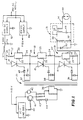
- The single figure of the drawings is a schematic diagram, partially in block diagram form, of the invention.
- Referring to the drawing, a high voltage d.c.
power supply 10 receives 115 V., 400Hz a.c. input and converts the same into high voltage d.c., preferrably 4 kV. d.c. A storage capacitor 11 connected between the positive output terminal ofsupply 10 and ground receives continuous charging current fromsupply 10 until charged to 4kV. Capacitor 11 may suitably have a value of 1 µF (mfd). The positively charged terminal of capacitor 11 is connected through a commutatinginductor 12 to the anode of afirst SCR 14. The cathode ofSCR 14 is connected to the anode of asecond SCR 15, the cathode of which is connected to the anode of athird SCR 16. - A protective network comprised of three identical, series connected
sections inductor 21, aresistor 23 connected in parallel with acapacitor 23 with the upper node of the parallel combination connected in series withresistor 21 and with the lower node of the combination connected in series with asecond resistor 24. Theupper end 25 ofnetwork section 17 is connected to the anode ofSCR 14. Thelower end 26 ofnetwork section 17, which is also the upper end ofnetwork section 18, is connected to the line interconnecting the cathode ofSCR 14 and the anode ofSCR 15. Similarly, the lower end of section 18 -upper end 27 ofsection 19 is connected to the line interconnecting the cathode ofSCR 15 and the anode ofSCR 16. - The cathode of
SCR 16 is connected to oneinput terminal 30 of theconditioning circuit 31. Theother input terminal 32 ofconditioning circuit 31 is grounded. Conditioningcircuit 31 functions to reshape the substantially rectangular waveform of the discharge current from storage capacitor 11 to insert at the leading edge thereof an extra high voltage, very short duration spike. The reshaped waveform promotes ionization of the gases surrounding the engine igniter plug and improves the efficiency of the spark discharge through the igniter plug. -
Terminal 30 is connected to one end of the primary winding of atransformer 33. The other end of the primary wiring is grounded through acapacitor 49. One end of the secondary winding oftransformer 33 is connected to the input end of the primary winding thereof and the opposite end of the secondary winding is connected throughoutput terminal 34 to one electrode of anigniter plug 48 located in the engine combustion chamber. The other electrode ofigniter plug 48 is grounded. The cathode of adiode 50 is connected to the input end of the primary oftransformer 33. The anode ofdiode 50 is grounded.Diode 50 damps the negative voltage induced at the input end of the primary oftransformer 33 when the discharge pulse from storage capacitor 11 ends, preventing damage to the SCRs and improving the efficiency of the conditioning circuit. - A
pulse transformer 35 having a singleprimary winding 36 and three secondary windings 37 - 39 supplies simultaneous trigger impulses to the gates of SCRs 14 - 16 when a trigger pulse is applied toprimary winding 36. Trigger pulses are generated by a commercially available integrated circuit IC-1, suitably type NE 555, a product of National Semiconductor Corp., Santa Clara, California. IC-1 is adjusted to generate negative-going pulses online 40 at a rate of from 2-4 p.p.s. The pulses online 40 are fed to the base of adriver transistor 41 for amplification prior to application to input winding 36 ofpulse transformer 35.Transistor 41 is protected against the application of overvoltage by aspark gap 42 and against the application of reverse currents by a resistor 43 -diode 44 combination connected from the collector oftransistor 41 to ground. - The secondary windings 37-39 of
pulse transformer 35 are respectively connected between the gate and cathode electrodes of SCRs 14-16 and are phased with respect toprimary winding 36 to generate a positive-going pulse at the SCR gates when a trigger pulse is applied to primary 36. The positive pulses on the gates of the SCRs switch them into conduction simultaneously to rapidly discharge the charge on capacitor 11 through theconditioning circuit 31 and generate an ignition spark atigniter plug 33. At the end of the surge of discharge current, the reverse voltages induced ininductor 12 and theinductors 21 of network sections 17-19 momentarily reverse bias SCRs 14-16 and render them again nonconductive until the appearance of the next trigger pulse. -
Diodes transistor 41 receive input power at +15 V. from a 15 V.d.c. regulated supply powered by the 115 V.a.c source. - Again referring to network sections 17-19,
resistors Capacitors 23 provide protection against the appearance of excessive voltage across any of the SCRs 14-16 which may be slow in switching.Inductors 21 andresistor 22 provide di/dt and current limiting when capacitors C23 discharge. In the specific embodiment of the invention disclosed, each of the SCRs is stressed only to the extent of one-third of the total charge voltage of capacitor 11. Moreover, should one or more, but less than all, of the SCRs 14-16 fail by short circuit, the remaining unaffected SCR will still function to provide engine spark.
Claims (10)
- A gas turbine engine ignition system comprising:
a storage capacitor;
means for supplying a continuous high voltage charging current to said storage capacitor;
a high voltage conditioning circuit having an input transformer, said conditioning circuit having an input connection and an output connection;
an igniter plug connected to said output connection of said conditioning circuit;
at least two semiconductor controlled rectifiers (SCRs);
each having anode, cathode and gate electrodes;
said SCRs being connected in series between said storage capacitor and said high voltage conditioning circuit;
said SCRs being normally nonconductive to block the flow of current from said storage capacitor to said conditioning circuit;
a protective network connected in parallel with said series connected SCRs, said network including a plurality of identical sections, each of said sections having an input terminal and an output terminal;
said sections being equal in number to the number of SCRs;
said network sections being connected in series with the output terminal of each said section being connected to the input terminal of the one of said sections following in said series;
said input terminal and said output terminal of each of said network sections being connected across the anode and cathode electrodes of a different one of said SCRs;
said protective network forming a voltage divider for dividing the charge voltage of said storage capacitor equally across said SCRs; and
means for applying a periodic triggering voltage simultaneously to said gate electrodes of each of said SCRs to render SCRs conductive substantially simultaneously and thereby discharge the charge stored on said storage capacitor into said conditioning circuit. - An ignition system as claimed in claim 1 wherein each of said sections of said protective network includes an inductor and a resistor connected in series.
- An ignition system as claimed in claim 2 wherein each of said network sections of said protective network includes a capacitor, said capacitor of each said section being connected in parallel with said resistor of said section.
- An ignition system as claimed in claim 1 wherein said means for applying a triggering voltage includes:
a pulse transformer, said pulse transformer having a primary winding and a plurality of secondary windings, said secondary windings being equal in number to the number of said SCRs in said system;
each of said secondary windings having a first and a second output terminal;
said secondary windings being arranged to produce outputs of the same phase at each of said first output terminals thereof;
said first and second output terminals of each of said secondary windings being respectively connected to said gate and cathode electrodes of a separate one of said SCRs. - An ignition system as claimed in claim 1 wherein the charge conducted by said SCRs from said storage capacitor into said conditioning circuit when said SCRs are rendered conductive is a pulse of current having a substantially rectangular waveform and wherein said conditioning circuit reshapes said current waveform to provide an extra high voltage, short duration spike at the leading edge thereof.
- An ignition system as claimed in claim 5, wherein said transformer of said conditioning circuit includes:
a primary winding and a secondary winding with one end each of said primary winding and said secondary winding being connected together to form said input connection of said conditioning circuit;
said conditioning circuit further including:
a conditioning capacitor having input and output terminals;
the end of said primary winding of said conditioning circuit transformer opposite said one end thereof being connected to said input terminal of said conditioning capacitor;
said output terminal of said conditioning circuit capacitor being grounded;
the end of said secondary winding of said conditioning circuit transformer opposite said one end thereof forming said output connection of said conditioning circuit; and
said igniter plug having a pair of discharge electrodes;
one of said discharge electrodes being connected to said conditioning circuit output terminal, the other of said discharge electrodes being grounded. - An ignition system as claimed in claim 6 with additionally:
a damping diode;
said damping diode being connected between said input connection of said conditioning circuit and ground to damp oscillations in said conditioning circuit. - An ignition system as claimed in claim 6 wherein said means for applying a triggering voltage includes:
a pulse transformer;
said pulse transformer having a primary winding and a plurality of secondary windings, said secondary windings being equal in number to the number of said SCRs in said system;
each of said secondary windings having a first and a second output terminal;
said secondary windings being arranged to produce outputs of the same phase at each of said first output terminals thereof;
said first and second output terminals of each of said secondary windings being respectively connected to said gate and cathode electrodes of a separate one of said SCRs. - An ignition system as claimed in claim 8 wherein said means for applying a periodic triggering voltage includes:
a pulse generator;
said pulse generator being of the free running type and being arranged to supply input pulses to said primary winding of said pulse transformer. - An ignition system as claimed in claim 9 wherein said pulse generator operator to generate pulses at a rate of from about 2 to 4 pulses per second.
Applications Claiming Priority (2)
| Application Number | Priority Date | Filing Date | Title |
|---|---|---|---|
| US312215 | 1981-10-19 | ||
| US07/312,215 US5053913A (en) | 1989-02-17 | 1989-02-17 | Capacitive discharge ignition exciter using scr discharge switches |
Publications (3)
| Publication Number | Publication Date |
|---|---|
| EP0382907A2 EP0382907A2 (en) | 1990-08-22 |
| EP0382907A3 EP0382907A3 (en) | 1991-05-02 |
| EP0382907B1 true EP0382907B1 (en) | 1995-01-18 |
Family
ID=23210411
Family Applications (1)
| Application Number | Title | Priority Date | Filing Date |
|---|---|---|---|
| EP89121809A Expired - Lifetime EP0382907B1 (en) | 1989-02-17 | 1989-11-25 | Capacitive discharge ignition exciter using SCR discharge switches |
Country Status (5)
| Country | Link |
|---|---|
| US (1) | US5053913A (en) |
| EP (1) | EP0382907B1 (en) |
| JP (1) | JPH02241933A (en) |
| CA (1) | CA2003410C (en) |
| DE (1) | DE68920729T2 (en) |
Families Citing this family (20)
| Publication number | Priority date | Publication date | Assignee | Title |
|---|---|---|---|---|
| US5347422A (en) * | 1992-09-09 | 1994-09-13 | Unison Industries Limited Partnership | Apparatus and method for an ignition system |
| EP0612376B1 (en) * | 1992-09-11 | 1996-11-20 | Unison Industries Limited Partnership | Capacitive discharge ignition system with self-triggering solid state switch |
| US5473502A (en) * | 1992-09-22 | 1995-12-05 | Simmonds Precision Engine Systems | Exciter with an output current multiplier |
| US5488536A (en) * | 1993-04-01 | 1996-01-30 | Simmonds Precision Engine Systems, Inc. | Exciter circuit using gated switches |
| CA2128036C (en) * | 1993-07-15 | 2003-11-04 | Howard Vincent Bonavia | Ignition system using multiple gated switches with variable discharge energy levels and rates |
| US5592118A (en) * | 1994-03-09 | 1997-01-07 | Cooper Industries, Inc. | Ignition exciter circuit with thyristors having high di/dt and high voltage blockage |
| US5656966A (en) * | 1994-03-09 | 1997-08-12 | Cooper Industries, Inc. | Turbine engine ignition exciter circuit including low voltage lockout control |
| US5898122A (en) * | 1996-07-02 | 1999-04-27 | Motorola, Inc. | Squib ignitor circuit and method thereof |
| US6603216B2 (en) * | 2001-10-10 | 2003-08-05 | Champion Aerospace Inc. | Exciter circuit with ferro-resonant transformer network for an ignition system of a turbine engine |
| US6670777B1 (en) | 2002-06-28 | 2003-12-30 | Woodward Governor Company | Ignition system and method |
| US7355300B2 (en) * | 2004-06-15 | 2008-04-08 | Woodward Governor Company | Solid state turbine engine ignition exciter having elevated temperature operational capability |
| US7768767B2 (en) * | 2006-05-05 | 2010-08-03 | Pratt & Whitney Canada Corp. | Triggered pulsed ignition system and method |
| US8240194B2 (en) * | 2009-07-30 | 2012-08-14 | Ford Global Technologies, Llc | Methods and systems for diagnostics of an emission system with more than one SCR region |
| US20130111914A1 (en) * | 2011-04-27 | 2013-05-09 | Champion Aerospace Llc | Aircraft ignition system and method of operating the same |
| RU2494314C1 (en) * | 2012-02-03 | 2013-09-27 | Открытое акционерное общество "Уфимское научно-производственное предприятие "Молния" | Ignition method of combustion chamber of aircraft gas-turbine engines |
| US9622331B2 (en) | 2012-12-26 | 2017-04-11 | Unison Industries, Llc | Discharge switch device for ignition excitation system |
| FR3032232B1 (en) | 2015-01-30 | 2017-03-10 | Meggitt (France) | HIGH ENERGY IGNITION GENERATOR, IN PARTICULAR FOR GAS TURBINE |
| CN110492877A (en) * | 2018-05-15 | 2019-11-22 | 维谛公司 | A thyristor drive circuit |
| CN109458260B (en) * | 2018-11-28 | 2020-12-08 | 陕西航空电气有限责任公司 | Discharge trigger holding circuit of variable-frequency and variable-energy ignition device of aircraft engine |
| US11519335B1 (en) | 2021-08-27 | 2022-12-06 | Unison Industries, Llc | Turbine engine ignition system and method |
Family Cites Families (12)
| Publication number | Priority date | Publication date | Assignee | Title |
|---|---|---|---|---|
| FR1326043A (en) * | 1962-06-08 | 1963-05-03 | Bosch Gmbh Robert | Ignition system for internal combustion engine |
| US3531738A (en) * | 1968-04-24 | 1970-09-29 | Bendix Corp | Continuous duty ignition system |
| US3605714A (en) * | 1969-06-11 | 1971-09-20 | Eltra Corp | Contactless ignition system |
| US3619638A (en) * | 1969-09-25 | 1971-11-09 | Bendix Corp | Pulse generating apparatus |
| DE3009796C2 (en) * | 1980-03-14 | 1984-04-12 | Deutsche Forschungs- und Versuchsanstalt für Luft- und Raumfahrt e.V., 5000 Köln | Rotation speed sensor based on a ring laser |
| DE3101568C2 (en) * | 1981-01-20 | 1986-01-09 | Wollank, Gerhard, Prof. Dipl.-Phys., 5040 Brühl | Circuit arrangement for operating low-pressure discharge lamps with adjustable luminous flux |
| JPS5888468A (en) * | 1981-11-24 | 1983-05-26 | Nissan Motor Co Ltd | Ignition device in internal-combustion engine |
| US4705013A (en) * | 1985-10-28 | 1987-11-10 | Minks Floyd M | Regulated power supply for a solid state ignition system |
| DE3731412A1 (en) * | 1986-11-08 | 1988-05-11 | Bosch Gmbh Robert | High-voltage switch |
| DE3731393A1 (en) * | 1987-09-18 | 1989-04-06 | Bosch Gmbh Robert | HIGH VOLTAGE SWITCH |
| US4839772A (en) * | 1988-03-21 | 1989-06-13 | Bang H. Mo | Capacitive discharge electronic ignition system for automobiles |
| FR2636678B1 (en) * | 1988-09-20 | 1994-04-15 | Labo Industrie | HIGH ENERGY IGNITION GENERATOR, PARTICULARLY FOR GAS TURBINE |
-
1989
- 1989-02-17 US US07/312,215 patent/US5053913A/en not_active Expired - Lifetime
- 1989-11-20 CA CA002003410A patent/CA2003410C/en not_active Expired - Lifetime
- 1989-11-25 DE DE68920729T patent/DE68920729T2/en not_active Expired - Lifetime
- 1989-11-25 EP EP89121809A patent/EP0382907B1/en not_active Expired - Lifetime
-
1990
- 1990-02-16 JP JP2034050A patent/JPH02241933A/en active Pending
Also Published As
| Publication number | Publication date |
|---|---|
| EP0382907A3 (en) | 1991-05-02 |
| CA2003410A1 (en) | 1990-08-17 |
| US5053913A (en) | 1991-10-01 |
| CA2003410C (en) | 1995-10-03 |
| EP0382907A2 (en) | 1990-08-22 |
| DE68920729T2 (en) | 1995-09-07 |
| DE68920729D1 (en) | 1995-03-02 |
| JPH02241933A (en) | 1990-09-26 |
Similar Documents
| Publication | Publication Date | Title |
|---|---|---|
| US5053913A (en) | Capacitive discharge ignition exciter using scr discharge switches | |
| CA2181092C (en) | Method and apparatus for controllably generating sparks in an ignition system or the like | |
| US5568801A (en) | Plasma arc ignition system | |
| US4510915A (en) | Plasma ignition system for an internal combustion engine | |
| US5656966A (en) | Turbine engine ignition exciter circuit including low voltage lockout control | |
| US4448181A (en) | Plasma ignition system for an internal combustion engine | |
| US5510952A (en) | Ignition system using multiple gated switches with variable discharge energy levels and rates | |
| CA2185125C (en) | A turbine engine ignition exciter circuit | |
| US4441479A (en) | Ignition system for a multi-cylinder internal combustion engine of a vehicle | |
| US5473502A (en) | Exciter with an output current multiplier | |
| US5446348A (en) | Apparatus for providing ignition to a gas turbine engine and method of short circuit detection | |
| US3242420A (en) | Ignition system | |
| JP3470939B2 (en) | Pulse power supply for electric dust collection and its protection method | |
| US5862033A (en) | Exciter circuit | |
| EP0628719B1 (en) | Ignition apparatus employing a lower voltage capacitor discharge self-triggering circuit | |
| US3619638A (en) | Pulse generating apparatus | |
| US3974816A (en) | Electronic ignition system with combined output from multiple coils | |
| EP0071526B1 (en) | An ignition system for an internal combustion engine | |
| US2790935A (en) | Multiple ignitor capacitor ignition system | |
| GB1182726A (en) | Electrical Spark Generating Apparatus | |
| US4149509A (en) | Breakerless ignition system | |
| US3601656A (en) | Silicon diode protection means | |
| US3628089A (en) | Pulse-generating apparatus | |
| US4037576A (en) | Ignition system for internal-combustion engines negative bias trigger | |
| CA2535578C (en) | Method and apparatus for controllably generating sparks in an ignition system or the like |
Legal Events
| Date | Code | Title | Description |
|---|---|---|---|
| PUAI | Public reference made under article 153(3) epc to a published international application that has entered the european phase |
Free format text: ORIGINAL CODE: 0009012 |
|
| AK | Designated contracting states |
Kind code of ref document: A2 Designated state(s): DE FR GB IT |
|
| PUAL | Search report despatched |
Free format text: ORIGINAL CODE: 0009013 |
|
| AK | Designated contracting states |
Kind code of ref document: A3 Designated state(s): DE FR GB IT |
|
| 17P | Request for examination filed |
Effective date: 19911030 |
|
| 17Q | First examination report despatched |
Effective date: 19931214 |
|
| GRAA | (expected) grant |
Free format text: ORIGINAL CODE: 0009210 |
|
| AK | Designated contracting states |
Kind code of ref document: B1 Designated state(s): DE FR GB IT |
|
| PG25 | Lapsed in a contracting state [announced via postgrant information from national office to epo] |
Ref country code: IT Free format text: LAPSE BECAUSE OF FAILURE TO SUBMIT A TRANSLATION OF THE DESCRIPTION OR TO PAY THE FEE WITHIN THE PRESCRIBED TIME-LIMIT;WARNING: LAPSES OF ITALIAN PATENTS WITH EFFECTIVE DATE BEFORE 2007 MAY HAVE OCCURRED AT ANY TIME BEFORE 2007. THE CORRECT EFFECTIVE DATE MAY BE DIFFERENT FROM THE ONE RECORDED. Effective date: 19950118 |
|
| REF | Corresponds to: |
Ref document number: 68920729 Country of ref document: DE Date of ref document: 19950302 |
|
| ET | Fr: translation filed | ||
| PLBE | No opposition filed within time limit |
Free format text: ORIGINAL CODE: 0009261 |
|
| STAA | Information on the status of an ep patent application or granted ep patent |
Free format text: STATUS: NO OPPOSITION FILED WITHIN TIME LIMIT |
|
| 26N | No opposition filed | ||
| REG | Reference to a national code |
Ref country code: GB Ref legal event code: IF02 |
|
| PGFP | Annual fee paid to national office [announced via postgrant information from national office to epo] |
Ref country code: FR Payment date: 20081117 Year of fee payment: 20 |
|
| PGFP | Annual fee paid to national office [announced via postgrant information from national office to epo] |
Ref country code: DE Payment date: 20081223 Year of fee payment: 20 |
|
| PGFP | Annual fee paid to national office [announced via postgrant information from national office to epo] |
Ref country code: GB Payment date: 20081128 Year of fee payment: 20 |
|
| REG | Reference to a national code |
Ref country code: GB Ref legal event code: PE20 Expiry date: 20091124 |
|
| PG25 | Lapsed in a contracting state [announced via postgrant information from national office to epo] |
Ref country code: GB Free format text: LAPSE BECAUSE OF EXPIRATION OF PROTECTION Effective date: 20091124 |