EP0382145B1 - Switch - Google Patents
Switch Download PDFInfo
- Publication number
- EP0382145B1 EP0382145B1 EP90102241A EP90102241A EP0382145B1 EP 0382145 B1 EP0382145 B1 EP 0382145B1 EP 90102241 A EP90102241 A EP 90102241A EP 90102241 A EP90102241 A EP 90102241A EP 0382145 B1 EP0382145 B1 EP 0382145B1
- Authority
- EP
- European Patent Office
- Prior art keywords
- negative pressure
- contact
- fluid passage
- pressure chamber
- switch
- Prior art date
- Legal status (The legal status is an assumption and is not a legal conclusion. Google has not performed a legal analysis and makes no representation as to the accuracy of the status listed.)
- Expired - Lifetime
Links
- 239000012530 fluid Substances 0.000 claims description 64
- 238000000926 separation method Methods 0.000 claims description 6
- 125000006850 spacer group Chemical group 0.000 description 3
- 239000004020 conductor Substances 0.000 description 2
- 238000000034 method Methods 0.000 description 2
- 230000002093 peripheral effect Effects 0.000 description 2
- 238000005422 blasting Methods 0.000 description 1
- 239000011810 insulating material Substances 0.000 description 1
- 238000012423 maintenance Methods 0.000 description 1
- 239000000463 material Substances 0.000 description 1
Images


Classifications
-
- H—ELECTRICITY
- H01—ELECTRIC ELEMENTS
- H01H—ELECTRIC SWITCHES; RELAYS; SELECTORS; EMERGENCY PROTECTIVE DEVICES
- H01H33/00—High-tension or heavy-current switches with arc-extinguishing or arc-preventing means
- H01H33/70—Switches with separate means for directing, obtaining, or increasing flow of arc-extinguishing fluid
- H01H33/88—Switches with separate means for directing, obtaining, or increasing flow of arc-extinguishing fluid the flow of arc-extinguishing fluid being produced or increased by movement of pistons or other pressure-producing parts
- H01H33/90—Switches with separate means for directing, obtaining, or increasing flow of arc-extinguishing fluid the flow of arc-extinguishing fluid being produced or increased by movement of pistons or other pressure-producing parts this movement being effected by or in conjunction with the contact-operating mechanism
- H01H33/91—Switches with separate means for directing, obtaining, or increasing flow of arc-extinguishing fluid the flow of arc-extinguishing fluid being produced or increased by movement of pistons or other pressure-producing parts this movement being effected by or in conjunction with the contact-operating mechanism the arc-extinguishing fluid being air or gas
-
- H—ELECTRICITY
- H01—ELECTRIC ELEMENTS
- H01H—ELECTRIC SWITCHES; RELAYS; SELECTORS; EMERGENCY PROTECTIVE DEVICES
- H01H9/00—Details of switching devices, not covered by groups H01H1/00 - H01H7/00
- H01H9/30—Means for extinguishing or preventing arc between current-carrying parts
-
- H—ELECTRICITY
- H01—ELECTRIC ELEMENTS
- H01H—ELECTRIC SWITCHES; RELAYS; SELECTORS; EMERGENCY PROTECTIVE DEVICES
- H01H33/00—High-tension or heavy-current switches with arc-extinguishing or arc-preventing means
- H01H33/70—Switches with separate means for directing, obtaining, or increasing flow of arc-extinguishing fluid
- H01H33/88—Switches with separate means for directing, obtaining, or increasing flow of arc-extinguishing fluid the flow of arc-extinguishing fluid being produced or increased by movement of pistons or other pressure-producing parts
- H01H33/90—Switches with separate means for directing, obtaining, or increasing flow of arc-extinguishing fluid the flow of arc-extinguishing fluid being produced or increased by movement of pistons or other pressure-producing parts this movement being effected by or in conjunction with the contact-operating mechanism
- H01H2033/906—Switches with separate means for directing, obtaining, or increasing flow of arc-extinguishing fluid the flow of arc-extinguishing fluid being produced or increased by movement of pistons or other pressure-producing parts this movement being effected by or in conjunction with the contact-operating mechanism with pressure limitation in the compression volume, e.g. by valves or bleeder openings
-
- H—ELECTRICITY
- H01—ELECTRIC ELEMENTS
- H01H—ELECTRIC SWITCHES; RELAYS; SELECTORS; EMERGENCY PROTECTIVE DEVICES
- H01H33/00—High-tension or heavy-current switches with arc-extinguishing or arc-preventing means
- H01H33/70—Switches with separate means for directing, obtaining, or increasing flow of arc-extinguishing fluid
- H01H33/88—Switches with separate means for directing, obtaining, or increasing flow of arc-extinguishing fluid the flow of arc-extinguishing fluid being produced or increased by movement of pistons or other pressure-producing parts
- H01H33/90—Switches with separate means for directing, obtaining, or increasing flow of arc-extinguishing fluid the flow of arc-extinguishing fluid being produced or increased by movement of pistons or other pressure-producing parts this movement being effected by or in conjunction with the contact-operating mechanism
- H01H33/901—Switches with separate means for directing, obtaining, or increasing flow of arc-extinguishing fluid the flow of arc-extinguishing fluid being produced or increased by movement of pistons or other pressure-producing parts this movement being effected by or in conjunction with the contact-operating mechanism making use of the energy of the arc or an auxiliary arc
Definitions
- the present invention relates to a switch and, more particularly, to a switch provided with a negative pressure generator for producing a gas-blast flow toward the arc.
- a conventional switch of this type is composed of a sealed container charged with an arc extinguishing fluid such as SF6 gas, a stationary contact and a movable contact provided in the container in such a manner as to be relatively separable from each other, a booster having a boosting chamber for boosting the arc extinguishing fluid by the energy of the arc produced by the separation of the contacts, and a negative pressure generator having a negative pressure chamber for producing a negative pressure by the relative movement of a cylinder and a piston induced by the separating operation of the contacts, as is disclosed in JP-B-62-16485. To the arc between the separated contacts, a gas flow produced from the booster chamber toward the negative pressure chamber is blasted, thereby extinguishing the arc.
- This known switch has the features set forth in the first part of claim 1.
- the negative pressure generator is actuated from the initial stage of the cut-off operation, thereby producing a negative pressure.
- the operating device of the switch must be so constructed as to produce a large operating force rapidly from the beginning of operation in correspondence with the negative pressure produced.
- This type of operating device generally uses compressed air, so that it is difficult to obtain a large operating force at the initial stage of operation, as is known from the plenum characteristic thereof.
- use of an operating device of another system disadvantageously expands the size thereof.
- a switch according to the present invention is capable of suppressing the generation of a negative pressure during the initial stage of the separation of the contacts, as described above. Therefore, the reacting force due to the generation of a negative pressure does not act on the operating device at the initial stage of the separating operation, and the operating device can be operated by a small operating force. After the end of the initial stage of the separating operation, it is possible to operate the operating device against the reaction force due to the generation of a negative pressure by the inertia force of the operating device obtained at the initial stage of the separating operation. It is therefore possible not only to miniaturize the operating device but also to adopt an operating device using compressed air.
- Fig. 1 is a vertical sectional view of an embodiment of a switch according to the present invention in the closed state.
- a cylindrical breaker container 2 are sealed by insulating spacers 1a, 1b, respectively, thereby constituting a sealed container.
- the sealed container is charged with an arc extinguishing fluid such as an SF6 gas.
- a stationary contact 3 is attached to the terminal at the central portion of the insulating spacer 1a.
- a movable contact 6 is brought into contact with the stationary contact 3 in such a manner as to face the stationary contact 3.
- a piston 6A and a center shaft 6B are integrally provided with the movable contact 6.
- the end portion of the center shaft 6B is slidably connected to a conductor 8 which is attached to the terminal of the insulating spacer 1b through a collector 7.
- a lever 10 connected to an operating device (not shown) is connected to the center shaft 6B through a link 13.
- the lever 10 is connected to a center shaft 10A which is rotatably supported by the breaker container 2. Accordingly, when the center shaft 10A of the lever 10 is rotated clockwise, the movable contact 6 is operated through the link 13 so as to open the breaker, while the counterclockwise rotation of the center shaft 10A of the lever 10 operates the movable contact 6 so as to close the breaker.
- a cylindrical insulating nozzle 5 which encloses the stationary contact 3 and a cylinder 14 which encloses the center shaft 6B and the conductor 8.
- the movable contact 6 is inserted into the throat 5A of the insulating nozzle 5 so as to come into contact with the stationary contact 3, and a booster chamber 4 including the contacting portion of the contacts 3, 6 is defined by the insulating nozzle 5 and the like.
- the insulating nozzle 5, the piston 6A and the cylinder 14 constitute a negative pressure generator, which is provided with a negative pressure chamber 15 formed at the portion at which insulating nozzle 5 and the piston 6A face each other.
- annular first fluid passage 11 On the inside of the cylinder 14 on the side of the insulating nozzle 5, an annular first fluid passage 11 is formed, as shown in Fig. 2.
- the negative pressure chamber 15 and the surrounding space 9 communicate with each other through a minute gap formed between the end surface 5B of the insulating nozzle 5 and the end surface of the piston 6A.
- the first fluid passage 11 is provided with an annular portion having a diameter D2 which is larger than the inner diameter D3 of the cylinder 14 and formed in the direction of the opening operation of the movable contact 6 extending over the distance of L4 from the end surface 5B of the insulating nozzle 5.
- the inner wall of the cylinder 14 at the portion between the point distant from the end surface 5B of the insulating nozzle by L2 and the point distant from the end surface 5B of the insulating nozzle 5 by L3 has the inner diameter of D3 which is substantially equal to the outer diameter D1 of the piston 6A.
- a second fluid passage 12 is formed on the inner wall of the cylinder 14 at the portion distant from the end surface 5B of the insulating nozzle 5 by not less than L3.
- the distances L2, L3 and the distance L1 by which the movable contact 6 is inserted into the throat 5A of the insulating nozzle 5 so as to fill the insulating nozzle 5 are set so as to satisfy the relationship L2 ⁇ L1 ⁇ L3.
- the negative pressure chamber 15 first communicates with the surrounding space 9 through the first fluid passage 11, but when the piston 6A moves by the distance of L2, the communication of the negative pressure chamber 15 with the surrounding space 9 is broken due to the contact between the outer peripheral surface of the piston 6A and the inner wall of the cylinder 14.
- the negative pressure chamber 15 communicates with the surrounding space 9 again through the second fluid passage 12.
- Fig. 3 shows the switch in the closed state.
- the movable contact 6 is in contact with the stationary contact 3.
- the booster chamber 4 is partitioned from the surrounding space 9 because the movable contact 6 fills the insulating nozzle 5.
- the negative pressure chamber 15 communicates with the surrounding space 9 through the first fluid passage 11.
- the pressure characteristic of the negative pressure chamber 15 exhibits a pressure characteristic curve B which is slightly gentle in comparison with a conventional pressure characteristic curve A, as shown in Fig. 7.
- a pressure characteristic curve B which is slightly gentle in comparison with a conventional pressure characteristic curve A, as shown in Fig. 7.
- the closing operation is carried out in the reverse order of the above-described opening operation.
- the lever 10 in the state shown in Fig. 6 is rotated counterclockwise, the communication between the negative pressure chamber 15 and the surrounding space 9 is broken in the state shown in Fig. 5, and the pressure of the negative pressure chamber 15 is raised.
- the closing state after the state shown in Fig. 4 the negative pressure chamber 15 communicates with the surrounding space 9 through the first fluid passage 11 and the pressure of the negative pressure chamber 15 is released into the surrounding space 9 through the first fluid passage 11, so that the pressure characteristic of the negative pressure chamber 15 exhibits a pressure rise curve D which is lower than a pressure rise curve C of a conventional negative pressure chamber without the first fluid passage 11, as shown in Fig. 8.
- the switch assumes the closed state, as shown in Fig. 3.
- the closing operation since it is also possible to suppress the raise of the pressure of the negative pressure chamber 15, as shown in Fig. 8, it is possible to reduce the size of the operating device which executes the closing operation against the negative pressure.
- the first fluid passage 11 is formed by an annular groove having the inner diameter D2 larger than the inner diameter D3 of the cylinder 14.
- Another example of the first fluid passage 11 is shown in Fig. 9.
- a plurality of grooves 14A having the length equivalent to the distance L2 from the end surface 5B of the insulating nozzle 5 are formed in the axial direction of the cylinder 14.
- Engaging portions 6a of the piston 6A are slidably engaged with the grooves 14A.
- the first fluid passage 11 is formed at the portions at which the grooves 14A and the engaging portions 6a face each other.
- Fig. 10 shows another embodiment of the present invention.
- the insulating nozzle 5 is cantilevered on one side of the container 2, and the cylinder 14 made of a material different from that of the insulating nozzle 5 is provided on the insulating nozzle 5.
- This structure makes it possible to reduce the size and the weight of the cylinder 14.
- the operation and the advantages are the same as in the embodiment shown in Fig. 1. It is also possible in this embodiment to make the piston 6a from an insulating material different from that of the movable contact 6.
- Fig. 11 is a sectional view of the main part of still another embodiment of the present invention.
- the same reference numerals denote the same or corresponding elements as or to those shown in Fig. 1.
- This embodiment is different from the above-described embodiments in the structure for actuating the negative generator behind the opening operation of the movable contact 6 by a predetermined time.
- the movable contact 6 and the piston 6A are made separately from each other so as to be connected with each other after the movable contact 6 slides by the distance L2, as shown in Fig. 11. Owing to this structure, the first fluid passage 11 is dispensed with.
- the second fluid passage 12 is the same as the second fluid passage 12 in the embodiment shown in Fig. 1.
- the piston 6A is operated together with the movable contact 6 so as to operate the negative pressure generator, thereby increasing the volume of the negative pressure chamber 15, as shown in Fig. 13.
- a fluid flow is formed through which the booster chamber 4 and the negative pressure chamber 15 communicate with each other and the pressures thereof are balanced.
- the arc between the contacts 3, 6 is extinguished by the blasting operation of the fluid flow.
- the pressure of the negative chamber 15 gradually rises and when the movable contact 6 reaches the point distant from the end surface of the cylinder 14 by L3 which is equivalent to the distance L3 shown in Fig. 1, the negative pressure chamber 15 and the surrounding space 9 communicate with each other through the second fluid passage 12 in the same way as in the embodiment shown in Fig. 1.
- This embodiment also enables the reaction force to the operating device at the initial stage of the separating operation to be reduced, thereby realizing a small-sized operating device like the above-described embodiments.
- Fig. 14 is a sectional view of the main part of a further embodiment of the present invention. This embodiment is different from the above-described embodiments in the structure for actuating the negative generator behind the separating operation of the movable contact 6 by a predetermined time.
- a valve mechanism is provided at the engaging portion of the movable contact 6 and the insulating nozzle 5.
- the valve mechanism is composed of a stepped portion provided at the throat of the insulating nozzle 5, a large-diameter portion 5a for allowing the booster chamber 4 and the negative pressure chamber 15 to communicate with each other until the movable contact 6 moves by the distance L2 to the left-hand side in Fig. 14, and a throat portion 5b for breaking the communication of both chambers 4, 15 during the period between the time when the the movable contact 6 has moved by the distance L2 and the time when the movable contact 6 has moved by the distance L1, which is equivalent to the distance L1 in Fig. 1.
- this embodiment is also so constructed as not to operate the negative pressure generator at the initial opening travel of the movable contact 6, it is possible to miniaturize and simplify the operating device and enhance the reliability in comparison with a conventional switch in which the negative pressure generator is activated from the start and produces a reaction force to the operating device.
- Fig. 17 is a sectional view of the main part of a still further embodiment of a switch according to the present invention.
- This embodiment is characterized in that a first fluid passage 20 is provided on the movable contact 6 so as to operate the negative pressure generator behind the opening operation of the movable contact 6 by a predetermined time.
- the first fluid passage 20 communicates with the booster chamber 4 on one end and with the negative pressure chamber 15 on the other end.
- the first fluid passage 20 is so designed that when the movable contact 6 travels the distance L2 in the direction of opening operation,the end of the first fluid passage 20 on the side of the booster chamber 4 is closed by the insulating nozzle 5 so as to interrupt the communication between the booster chamber 4 and the negative pressure chamber 14.
- Fig. 18 is a sectional view of the main part of a still further embodiment of a switch according to the present invention. In this embodiment, the operational relationship between the piston and the cylinder which constitute the negative pressure chamber 15 is reversed.
- a cylinder 21 is provided on the movable contact 6.
- the cylinder 21 is slidably fitted over the outer periphery of a cylindrical portion 22 which is integrally provided with the insulating nozzle 5.
- the cylinder 21, the insulating nozzle 5, which also serves as a piston, and the cylindrical portion 22 constitutes the negative pressure chamber 15.
- the fluid passage 23 is composed of a hole 22a formed at the cylindrical portion 22 and a hole 21a formed in the cylinder 21 such as to correspond to the hole 22a in the closed state shown in Fig. 18 and having a predetermined width in the direction of opening operation which allows the maintenance of communication with the hole 22a for a predetermined time.
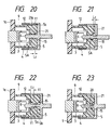
- Fig. 20 is a sectional view of the main part of a still further embodiment of a switch according to the present invention.
- the cylinder 21 connected to the movable contact 6 is provided on the outer periphery of the insulating nozzle 5 in such a manner as to enclose the contacting portion of the contacts 3, 6.
- a large-diameter portion 5c is formed at the right-hand end portion of the insulating nozzle 5.
- the dimension of the large-diameter portion 5c substantially coincides with the dimension of a small-diameter portion 21a of the cylinder 21.
- the first fluid passage 11 is formed, and on the left-hand side of the small-diameter portion 21a, the second fluid passage 12 is formed.
- Figs. 21 to 23 show still further embodiments of a switch according to the present invention. These embodiments are the same as those shown in Figs. 11, 14 and 17, respectively, except that the piston 6A is fixed and the cylinder is made movable.
- the same numerals are provided for the elements which are the same as those in the above-described embodiments, and detailed explanation thereof will be omitted.
- the negative pressure generator is not actuated at the initial stage of the opening operation of the movable contact 6.
- the communication between the booster chamber 4 and the negative pressure chamber 15 is broken, thereby actuating the negative pressure chamber pressure generator so as to produce a negative pressure.
- the movable contact 6 comes out of the throat portion 5b of the insulating nozzle 5, a flow of the arc extinguishing fluid is formed from the booster chamber 4 toward the negative pressure chamber 15.
- the blast flow extinguishes the arc between the contacts 3, 6 in the same way as in the above-described embodiments.
- the raised pressure in the negative pressure chamber 15 is released when the second fluid passage 12 of the cylinder 21 reaches the right-hand end of the insulating nozzle 5 and thereby open the negative pressure chamber 15 into the surrounding space 9 through the second fluid passage 12.
Landscapes
- Circuit Breakers (AREA)
- Switches Operated By Changes In Physical Conditions (AREA)
- Fluid-Pressure Circuits (AREA)
Description
- The present invention relates to a switch and, more particularly, to a switch provided with a negative pressure generator for producing a gas-blast flow toward the arc. A conventional switch of this type is composed of a sealed container charged with an arc extinguishing fluid such as SF₆ gas, a stationary contact and a movable contact provided in the container in such a manner as to be relatively separable from each other, a booster having a boosting chamber for boosting the arc extinguishing fluid by the energy of the arc produced by the separation of the contacts, and a negative pressure generator having a negative pressure chamber for producing a negative pressure by the relative movement of a cylinder and a piston induced by the separating operation of the contacts, as is disclosed in JP-B-62-16485. To the arc between the separated contacts, a gas flow produced from the booster chamber toward the negative pressure chamber is blasted, thereby extinguishing the arc. This known switch has the features set forth in the first part of claim 1.
- In a conventional switch provided with a booster and a negative pressure generator having the above-described structure, the negative pressure generator is actuated from the initial stage of the cut-off operation, thereby producing a negative pressure. For this reason, the operating device of the switch must be so constructed as to produce a large operating force rapidly from the beginning of operation in correspondence with the negative pressure produced. This type of operating device, however, generally uses compressed air, so that it is difficult to obtain a large operating force at the initial stage of operation, as is known from the plenum characteristic thereof. On the other hand, use of an operating device of another system disadvantageously expands the size thereof.
- Accordingly, it is an object of the present invention to eliminate the above-described problems in the prior art and to provide a switch which suppresses the rapid generation of a reaction force in a negative pressure chamber at the initial stage of operation so as to enable the miniaturization of an operating device.
- The present invention achieves this aim by the features included in claim 1.
- A switch according to the present invention is capable of suppressing the generation of a negative pressure during the initial stage of the separation of the contacts, as described above. Therefore, the reacting force due to the generation of a negative pressure does not act on the operating device at the initial stage of the separating operation, and the operating device can be operated by a small operating force. After the end of the initial stage of the separating operation, it is possible to operate the operating device against the reaction force due to the generation of a negative pressure by the inertia force of the operating device obtained at the initial stage of the separating operation. It is therefore possible not only to miniaturize the operating device but also to adopt an operating device using compressed air.
- The above and other objects, features and advantages of the present invention will become clear from the following description of the preferred embodiments thereof, taken in conjunction with the accompanying drawings.
-
- Fig. 1 is a sectional view of an embodiment of a switch according to the present invention;
- Fig. 2 is a sectional view of the embodiment shown in Fig. 1, taken along the line II - II;
- Figs. 3 to 6 are sectional views of different operational states of the embodiment shown in Fig. 1;
- Figs. 7 and 8 are pressure characteristic curves of the embodiment shown as compared with those of a conventional switch;
- Fig. 9 is a sectional view of another example of the portion shown in Fig. 2;
- Fig. 10 is a sectional view of another embodiment of a switch according to the present invention;
- Fig. 11 is a sectional view of the main part of still another embodiment of a switch according to the present invention;
- Figs. 12 and 13 are sectional views of the main part of the embodiment shown in Fig. 11, showing the operational process thereof;
- Fig. 14 is a sectional view of the main part of a further embodiment of a switch according to the present invention;
- Figs. 15 and 16 are sectional views of the main part of the embodiment shown in Fig. 14, showing the operational process thereof;
- Fig. 17 shows the main part of a still further embodiment of a switch according to the present invention;
- Figs. 18 and 19 are sectional views of the main parts of still further embodiments of a switch according to the present invention, showing different operational states thereof; and
- Figs. 20 to 23 are sectional views of the main parts of still further embodiments of a switch according to the present invention.
- Embodiments of the present invention will be explained hereinunder with reference to the accompanying drawings.
- Fig. 1 is a vertical sectional view of an embodiment of a switch according to the present invention in the closed state. In Fig. 1, both ends of a
cylindrical breaker container 2 are sealed byinsulating spacers stationary contact 3 is attached to the terminal at the central portion of theinsulating spacer 1a. Amovable contact 6 is brought into contact with thestationary contact 3 in such a manner as to face thestationary contact 3. Apiston 6A and acenter shaft 6B are integrally provided with themovable contact 6. The end portion of thecenter shaft 6B is slidably connected to aconductor 8 which is attached to the terminal of theinsulating spacer 1b through acollector 7. To thecenter shaft 6B, alever 10 connected to an operating device (not shown) is connected through alink 13. Thelever 10 is connected to acenter shaft 10A which is rotatably supported by thebreaker container 2. Accordingly, when thecenter shaft 10A of thelever 10 is rotated clockwise, themovable contact 6 is operated through thelink 13 so as to open the breaker, while the counterclockwise rotation of thecenter shaft 10A of thelever 10 operates themovable contact 6 so as to close the breaker. - To the interior of the
breaker container 2 are fixed a cylindrical insulatingnozzle 5 which encloses thestationary contact 3 and acylinder 14 which encloses thecenter shaft 6B and theconductor 8. In the closed state shown in Fig. 1, themovable contact 6 is inserted into thethroat 5A of theinsulating nozzle 5 so as to come into contact with thestationary contact 3, and abooster chamber 4 including the contacting portion of thecontacts insulating nozzle 5 and the like. Theinsulating nozzle 5, thepiston 6A and thecylinder 14 constitute a negative pressure generator, which is provided with anegative pressure chamber 15 formed at the portion at which insulatingnozzle 5 and thepiston 6A face each other. On the inside of thecylinder 14 on the side of theinsulating nozzle 5, an annularfirst fluid passage 11 is formed, as shown in Fig. 2. In the closed state shown in Fig. 1, thenegative pressure chamber 15 and the surroundingspace 9 communicate with each other through a minute gap formed between theend surface 5B of theinsulating nozzle 5 and the end surface of thepiston 6A. Thefirst fluid passage 11 is provided with an annular portion having a diameter D₂ which is larger than the inner diameter D₃ of thecylinder 14 and formed in the direction of the opening operation of themovable contact 6 extending over the distance of L₄ from theend surface 5B of theinsulating nozzle 5. The inner wall of thecylinder 14 at the portion between the point distant from theend surface 5B of the insulating nozzle by L₂ and the point distant from theend surface 5B of theinsulating nozzle 5 by L₃ has the inner diameter of D₃ which is substantially equal to the outer diameter D₁ of thepiston 6A. On the inner wall of thecylinder 14 at the portion distant from theend surface 5B of theinsulating nozzle 5 by not less than L₃, asecond fluid passage 12 is formed. The distances L₂, L₃ and the distance L₁ by which themovable contact 6 is inserted into thethroat 5A of the insulatingnozzle 5 so as to fill theinsulating nozzle 5 are set so as to satisfy the relationship L₂ < L₁ < L₃. Consequently, when thepiston 6A moves in the direction of opening travel, thenegative pressure chamber 15 first communicates with the surroundingspace 9 through thefirst fluid passage 11, but when thepiston 6A moves by the distance of L₂, the communication of thenegative pressure chamber 15 with the surroundingspace 9 is broken due to the contact between the outer peripheral surface of thepiston 6A and the inner wall of thecylinder 14. When thepiston 6A further moves to the point distant from the end surface of thecylinder 14 by the distance of L₃, thenegative pressure chamber 15 communicates with the surroundingspace 9 again through thesecond fluid passage 12. - The opening operation of the embodiment of a switch according to the present invention shown in Fig. 1 will now be explained with reference to Figs. 3 to 6. Fig. 3 shows the switch in the closed state. At this time, the
movable contact 6 is in contact with thestationary contact 3. Thebooster chamber 4 is partitioned from the surroundingspace 9 because themovable contact 6 fills theinsulating nozzle 5. Thenegative pressure chamber 15 communicates with the surroundingspace 9 through thefirst fluid passage 11. - When the
lever 10 is rotated clockwise by an operating device (not shown), the outer peripheral surface of thepiston 6A closes thefirst fluid passage 11, as shown in Fig. 4, and a negative pressure is produced with the increase in the volume of thenegative pressure chamber 15. Although the negative pressure acts on the opening operation of themovable contact 6 as a reaction force, the operating device (not shown) operates thepiston 6A and themovable contact 6 so as to open the breaker against the reaction force by the inertia force obtained during the period from the closed state of the switch shown in Fig. 3 to the initial stage of the opening operation of the switch shown in Fig. 4. It is thus possible to reduce the influence of the reaction force of the negative pressure on the opening operation of themovable contact 6. - When the opening operation of the switch proceeds to a middle stage, as shown in Fig. 5, the
movable contact 6 comes out of thethroat portion 5A of theinsulating nozzle 5. Consequently, the arc extinguishing fluid in thebooster chamber 4 which is boosted by the energy of the arc generated by the separating operation between thestationary contact 3 and themovable contact 6 flows into thenegative pressure chamber 15 in the pressure-reduced state through thethroat portion 5A of theinsulating nozzle 5. The fluid flow blasts the arc. In a current region in which the arc energy is comparatively small, the arc is extinguished in the state of the middle stage of the opening operation shown in Fig. 5. In the case where the arc energy is larger, however, the pressures of both chambers are balanced by the arc extinguishing fluid which flows from thebooster chamber 4 to thenegative pressure chamber 15, thereby obstructing effective blast to the arc. When the opening operation comes to the final stage shown in Fig. 6, thepiston 6A reaches thesecond fluid passage 12 and thenegative pressure chamber 15 communicates with the surroundingspace 9 through thesecond fluid passage 12. Therefore, the arc extinguishing fluid in thebooster chamber 4 flows into thenegative pressure chamber 15 and further into the surroundingspace 9 through thesecond fluid passage 12. By this blast of the arc extinguishing fluid, the arc is extinguished. - As is clear from the above explanation of the opening operation, the pressure characteristic of the
negative pressure chamber 15 exhibits a pressure characteristic curve B which is slightly gentle in comparison with a conventional pressure characteristic curve A, as shown in Fig. 7. As a result, it is possible to reduce the size of an operating device for producing an output which resists the reaction force and to easily produce the operating device. - On the other hand, the closing operation is carried out in the reverse order of the above-described opening operation. When the
lever 10 in the state shown in Fig. 6 is rotated counterclockwise, the communication between thenegative pressure chamber 15 and the surroundingspace 9 is broken in the state shown in Fig. 5, and the pressure of thenegative pressure chamber 15 is raised. However, in the closing state after the state shown in Fig. 4, thenegative pressure chamber 15 communicates with the surroundingspace 9 through thefirst fluid passage 11 and the pressure of thenegative pressure chamber 15 is released into the surroundingspace 9 through thefirst fluid passage 11, so that the pressure characteristic of thenegative pressure chamber 15 exhibits a pressure rise curve D which is lower than a pressure rise curve C of a conventional negative pressure chamber without thefirst fluid passage 11, as shown in Fig. 8. Thereafter, the switch assumes the closed state, as shown in Fig. 3. In the closing operation, since it is also possible to suppress the raise of the pressure of thenegative pressure chamber 15, as shown in Fig. 8, it is possible to reduce the size of the operating device which executes the closing operation against the negative pressure. - In this embodiment, the
first fluid passage 11 is formed by an annular groove having the inner diameter D₂ larger than the inner diameter D₃ of thecylinder 14. Another example of thefirst fluid passage 11 is shown in Fig. 9. A plurality ofgrooves 14A having the length equivalent to the distance L₂ from theend surface 5B of the insulatingnozzle 5 are formed in the axial direction of thecylinder 14.Engaging portions 6a of thepiston 6A are slidably engaged with thegrooves 14A. Thefirst fluid passage 11 is formed at the portions at which thegrooves 14A and the engagingportions 6a face each other. - Fig. 10 shows another embodiment of the present invention. In this embodiment, the insulating
nozzle 5 is cantilevered on one side of thecontainer 2, and thecylinder 14 made of a material different from that of the insulatingnozzle 5 is provided on the insulatingnozzle 5. This structure makes it possible to reduce the size and the weight of thecylinder 14. The operation and the advantages are the same as in the embodiment shown in Fig. 1. It is also possible in this embodiment to make thepiston 6a from an insulating material different from that of themovable contact 6. - Fig. 11 is a sectional view of the main part of still another embodiment of the present invention. The same reference numerals denote the same or corresponding elements as or to those shown in Fig. 1.
- This embodiment is different from the above-described embodiments in the structure for actuating the negative generator behind the opening operation of the
movable contact 6 by a predetermined time. Themovable contact 6 and thepiston 6A are made separately from each other so as to be connected with each other after themovable contact 6 slides by the distance L₂, as shown in Fig. 11. Owing to this structure, thefirst fluid passage 11 is dispensed with. Thesecond fluid passage 12 is the same as thesecond fluid passage 12 in the embodiment shown in Fig. 1. - The operation of this embodiment will now be explained with reference to Figs. 11 to 13.
- In the closed state shown in Fig. 11, when the
movable contact 6 is driven in the direction of opening travel, namely, to the right-hand side in Fig. 11, themovable contact 6 solely operates until the sliding distance reaches L₂. During this time, thepiston 6A is held at the position shown in Fig. 11. The negative pressure generator therefore does not act and the volume of thenegative pressure chamber 15 does not increase. However, when the opening operation of themovable contact 6 proceeds and the movable contact is separated from thestationary contact 3, the pressure of thebooster chamber 6 rises due to the energy of the arc produced between bothcontacts movable contact 6 assumes the state shown in Fig. 12, themovable contact 6 is connected with thepiston 6A in the direction of opening travel. Thereafter, thepiston 6A is operated together with themovable contact 6 so as to operate the negative pressure generator, thereby increasing the volume of thenegative pressure chamber 15, as shown in Fig. 13. When themovable contact 6 comes out of the throat portion 5a of the insulatingnozzle 5, a fluid flow is formed through which thebooster chamber 4 and thenegative pressure chamber 15 communicate with each other and the pressures thereof are balanced. The arc between thecontacts negative chamber 15 gradually rises and when themovable contact 6 reaches the point distant from the end surface of thecylinder 14 by L₃ which is equivalent to the distance L₃ shown in Fig. 1, thenegative pressure chamber 15 and the surroundingspace 9 communicate with each other through thesecond fluid passage 12 in the same way as in the embodiment shown in Fig. 1. - This embodiment also enables the reaction force to the operating device at the initial stage of the separating operation to be reduced, thereby realizing a small-sized operating device like the above-described embodiments.
- Fig. 14 is a sectional view of the main part of a further embodiment of the present invention. This embodiment is different from the above-described embodiments in the structure for actuating the negative generator behind the separating operation of the
movable contact 6 by a predetermined time. - In this embodiment, a valve mechanism is provided at the engaging portion of the
movable contact 6 and the insulatingnozzle 5. As shown in Fig. 14, the valve mechanism is composed of a stepped portion provided at the throat of the insulatingnozzle 5, a large-diameter portion 5a for allowing thebooster chamber 4 and thenegative pressure chamber 15 to communicate with each other until themovable contact 6 moves by the distance L₂ to the left-hand side in Fig. 14, and athroat portion 5b for breaking the communication of bothchambers movable contact 6 has moved by the distance L₂ and the time when themovable contact 6 has moved by the distance L₁, which is equivalent to the distance L₁ in Fig. 1. - The operation of this embodiment will now be explained with reference to Figs. 14 to 16.
- When the
movable contact 6 is moved in the direction of separation in the closed stated shown in Fig. 14, since thebooster chamber 4 and thenegative pressure chamber 15 communicate with each other through thefirst fluid passage 11 formed by the large-diameter portion 5a, the negative pressure generator is not operated substantially and no negative pressure is produced in thenegative pressure chamber 15 in spite of an increasing volume of thenegative pressure chamber 15 until the breaker assumes the state shown in Fig. 15. However, when the breaker assumes the state shown in Fig. 15, since themovable contact 6 fills thethroat portion 5b, the communication between thebooster chamber 4 and thenegative pressure chamber 15 is broken. The pressure of the booster chamber is therefore risen by the energy of the arc produced by the separation of thecontacts negative pressure chamber 15 which is interrupted in communication with thebooster chamber 5, a negative pressure is produced by the increase in the volume. When the opening operation proceeds to the state shown in Fig. 16, themovable contact 6 comes out of thethroat portion 5b, whereby thebooster chamber 4 and thenegative pressure chamber 15 communicate with each other. As a result, the arc between thecontacts movable contact 6, thenegative pressure chamber 15 and the surroundingspace 9 communicate with each other through thesecond fluid passage 12. - Since this embodiment is also so constructed as not to operate the negative pressure generator at the initial opening travel of the
movable contact 6, it is possible to miniaturize and simplify the operating device and enhance the reliability in comparison with a conventional switch in which the negative pressure generator is activated from the start and produces a reaction force to the operating device. - Fig. 17 is a sectional view of the main part of a still further embodiment of a switch according to the present invention. This embodiment is characterized in that a
first fluid passage 20 is provided on themovable contact 6 so as to operate the negative pressure generator behind the opening operation of themovable contact 6 by a predetermined time. - In the closed state shown in Fig. 17, the
first fluid passage 20 communicates with thebooster chamber 4 on one end and with thenegative pressure chamber 15 on the other end. Thefirst fluid passage 20 is so designed that when themovable contact 6 travels the distance L₂ in the direction of opening operation,the end of thefirst fluid passage 20 on the side of thebooster chamber 4 is closed by the insulatingnozzle 5 so as to interrupt the communication between thebooster chamber 4 and thenegative pressure chamber 14. Therefore, although thepiston 6a moves in the same direction with the opening operation of themovable contact 6 and increases the volume of thenegative pressure chamber 15, since thebooster chamber 4 and thenegative pressure chamber 15 are in communication with each other by virtue of thefirst fluid passage 20, a negative pressure which acts on the operating device as a large reaction force is not produced in thenegative pressure chamber 15, thereby substantially preventing the operation of the negative pressure generator. However, when the end of thefirst fluid passage 20 on the side of thebooster chamber 4 is closed by the insulatingnozzle 5, a negative pressure is produced in thenegative pressure chamber 15 due to the increase of the volume of thenegative pressure chamber 15. When themovable contact 6 comes out of thethroat portion 5A of the insulatingnozzle 5, a flow of the arc extinguishing fluid is formed from thebooster chamber 4 toward thenegative pressure chamber 15. The blast flow extinguishes the arc between thecontacts - This embodiment also brings about the same advantages as the above-described embodiments.
- Fig. 18 is a sectional view of the main part of a still further embodiment of a switch according to the present invention. In this embodiment, the operational relationship between the piston and the cylinder which constitute the
negative pressure chamber 15 is reversed. - A
cylinder 21 is provided on themovable contact 6. Thecylinder 21 is slidably fitted over the outer periphery of acylindrical portion 22 which is integrally provided with the insulatingnozzle 5. Thecylinder 21, the insulatingnozzle 5, which also serves as a piston, and thecylindrical portion 22 constitutes thenegative pressure chamber 15. On the side wall of thecylinder 21 and thecylindrical portion 22 of the insulatingnozzle 5, afluid passage 23 controlled by the movement of thecylinder 21 is formed. Thefluid passage 23 is composed of ahole 22a formed at thecylindrical portion 22 and ahole 21a formed in thecylinder 21 such as to correspond to thehole 22a in the closed state shown in Fig. 18 and having a predetermined width in the direction of opening operation which allows the maintenance of communication with thehole 22a for a predetermined time. - As a result, even if the
movable contact 6 moves in the direction of operation, since thenegative pressure chamber 15 communicates with the surroundingspace 9 due to the communication between theholes fluid passage 23 for a predetermined time, the negative pressure substantially does not act on thenegative pressure chamber 15. However, when thehole 21a passes thehole 22a, the communication between thenegative pressure chamber 15 and the surroundingspace 9 is broken, whereby thenegative pressure chamber 15 produces a negative pressure. When themovable contact 6 comes out of thethroat portion 5b of the insulatingnozzle 5, a flow of the arc extinguishing fluid is formed from thebooster chamber 4 toward thenegative pressure chamber 15. The blast flow extinguishes the arc between thecontacts holes fluid passage 23 are released from each other, and thenegative pressure chamber 15 communicates with the surroundingspace 9, as shown in Fig. 19. This embodiment also brings about substantially the same advantages as the above-described embodiments. - Fig. 20 is a sectional view of the main part of a still further embodiment of a switch according to the present invention. In this embodiment, the
cylinder 21 connected to themovable contact 6 is provided on the outer periphery of the insulatingnozzle 5 in such a manner as to enclose the contacting portion of thecontacts nozzle 5. The dimension of the large-diameter portion 5c substantially coincides with the dimension of a small-diameter portion 21a of thecylinder 21. On the inner wall of thecylinder 21 which corresponds to the large-diameter portion 5c in the closed state, thefirst fluid passage 11 is formed, and on the left-hand side of the small-diameter portion 21a, thesecond fluid passage 12 is formed. - Therefore, at the initial stage of the opening operation of the
movable contact 6, although the volume of thenegative pressure chamber 15 increases, since thenegative pressure chamber 15 and the surroundingspace 9 communicate with each other through thefirst fluid passage 11, no negative pressure which acts on the operating device as a large reaction force is not produced in thenegative pressure chamber 15 unlike in the conventional switch. However, when the opening operation of themovable contact 6 is accelerated, the large-diameter portion 5a and thesmall diameter portion 21a fit each other, whereby thenegative pressure chamber 15 is closed. Thenegative pressure chamber 15 thereafter produces a negative pressure. When themovable contact 6 comes out of thethroat portion 5b of the insulatingnozzle 5, a flow of the arc extinguishing fluid is formed from thebooster chamber 4 toward thenegative pressure chamber 15. The blast flow extinguishes the arc between thecontacts second fluid passage 12 corresponds to the large-diameter portion 5c, thenegative pressure chamber 15 communicates with the surroundingspace 9. - According to this embodiment, it is possible not only to sufficiently reduce the volume of the
negative pressure chamber 15 at the initial stage but also to miniaturize the operating device as in the above-described embodiments. - Figs. 21 to 23 show still further embodiments of a switch according to the present invention. These embodiments are the same as those shown in Figs. 11, 14 and 17, respectively, except that the
piston 6A is fixed and the cylinder is made movable. The same numerals are provided for the elements which are the same as those in the above-described embodiments, and detailed explanation thereof will be omitted. - In any of these embodiments, the negative pressure generator is not actuated at the initial stage of the opening operation of the
movable contact 6. After themovable contact 6 has travelled a predetermined distance, the communication between thebooster chamber 4 and thenegative pressure chamber 15 is broken, thereby actuating the negative pressure chamber pressure generator so as to produce a negative pressure. When themovable contact 6 comes out of thethroat portion 5b of the insulatingnozzle 5, a flow of the arc extinguishing fluid is formed from thebooster chamber 4 toward thenegative pressure chamber 15. The blast flow extinguishes the arc between thecontacts negative pressure chamber 15 is released when thesecond fluid passage 12 of thecylinder 21 reaches the right-hand end of the insulatingnozzle 5 and thereby open thenegative pressure chamber 15 into the surroundingspace 9 through thesecond fluid passage 12. - According to these embodiments, it is also possible to simplify and miniaturize the operating device as in the above-described embodiments.
- As described above, according to the present invention, since a negative pressure generator which is actuated behind the separating operation of the movable contact by a predetermined time is provided, it is possible to suppress a rapid reaction force in the negative pressure chamber at the initial stage of the opening operation, thereby reducing the size of the operating device.
Claims (9)
- A switch comprising
a stationary cylindrical portion having one end closed to form a booster chamber (4),
an insulating nozzle (5) provided at the other end of said stationary cylindrical portion,
a first contact (3) secured to the interior of said stationary cylindrical portion,
a second contact (6) adapted to be brought into and out of contact with said first contact (3) through the throat portion (5A) of said insulating nozzle (5), and
a negative pressure chamber (15) for generating a negative pressure by the separating operation of said second contact (6), the negative pressure causing a fluid flow from said booster chamber (4) through said throat (5A) for extinguishing an arc generated upon separation of said second contact (6) from said first contact (3),
characterised by a fluid passage (11; 20; 23) which communicates with said negative pressure chamber (15) for admitting fluid thereto during the initial stage of the contact separating operation. - The switch of claim 1, including a cylinder (14) provided on said insulating nozzle (5) and a piston (6A) provided on said second contact (6), said piston (6A) being slidably guided by said cylinder (14), wherein said fluid passage (11) is provided at the engaging portions of said piston (6A) and cylinder (14) in the closed state of the switch and connects said negative pressure chamber (15) with the space of the cylinder (14) during the initial stage of said contact separating operation.
- The switch of claim 2, wherein said fluid passage (11) is an annular groove provided on the inner wall of said cylinder (14).
- The switch of claim 1, including a cylindrical portion (22) provided on said insulating nozzle (5) and a cylinder (21) provided on said second contact (6) and being slidably guided by said cylindrical portion (22), wherein said fluid passage (23) is provided at the engaging portions of said cylindrical portion (22) and cylinder (21) to connect said negative pressure chamber (15) with the surrounding space of said cylindrical portion (22) during the initial stage of said contact separating operation.
- The switch of claim 4, wherein said fluid passage (23) includes a first hole (22a) provided in said cylindrical portion (22) and a second hole (21a) provided in said cylinder (21) in correspondence with said first hole (22a).
- The switch of claim 1, wherein said fluid passage is provided at the throat (5a, 5b) of said insulating nozzle (5) and connects said negative pressure chamber (15) with said booster chamber (4) during the initial stage of said contact separation operation.
- The switch of claim 6, wherein said fluid passage is an annular groove forming a larger-diameter throat portion (5a) of said insulating nozzle (5).
- The switch of claim 1, wherein said fluid passage (20) is provided at the portion of said second contact (6) which penetrates said throat (5A) of said insulating nozzle (5) to connect said negative pressure chamber (15) with said booster chamber (4) during the initial stage of said contact separating operation.
- The switch of claim 8, wherein said fluid passage (20) is a communication hole provided in said second contact (6).
Applications Claiming Priority (2)
| Application Number | Priority Date | Filing Date | Title |
|---|---|---|---|
| JP27659/89 | 1989-02-08 | ||
| JP2765989 | 1989-02-08 |
Publications (3)
| Publication Number | Publication Date |
|---|---|
| EP0382145A2 EP0382145A2 (en) | 1990-08-16 |
| EP0382145A3 EP0382145A3 (en) | 1992-01-02 |
| EP0382145B1 true EP0382145B1 (en) | 1995-05-10 |
Family
ID=12227061
Family Applications (1)
| Application Number | Title | Priority Date | Filing Date |
|---|---|---|---|
| EP90102241A Expired - Lifetime EP0382145B1 (en) | 1989-02-08 | 1990-02-05 | Switch |
Country Status (5)
| Country | Link |
|---|---|
| US (1) | US5045651A (en) |
| EP (1) | EP0382145B1 (en) |
| KR (1) | KR0163584B1 (en) |
| CN (1) | CN1019870B (en) |
| DE (1) | DE69019184T2 (en) |
Families Citing this family (6)
| Publication number | Priority date | Publication date | Assignee | Title |
|---|---|---|---|---|
| JP2880543B2 (en) * | 1989-11-29 | 1999-04-12 | 株式会社日立製作所 | Gas switch |
| FR2696316B1 (en) * | 1992-10-06 | 1994-11-04 | Alsthom Gec | High or medium voltage circuit breaker with thermal expansion and additional suction blow-off. |
| CN107787516B (en) | 2015-04-13 | 2020-06-19 | Abb瑞士股份有限公司 | Devices that interrupt only non-short-circuit currents, especially isolating switches or earthing switches |
| EP3385969B1 (en) * | 2017-04-07 | 2021-10-20 | ABB Power Grids Switzerland AG | Gas-insulated circuit breaker and a method for breaking an electrical connection |
| FR3094836B1 (en) * | 2019-04-02 | 2021-07-09 | Pommier | Arc breaking device |
| CN110136999B (en) * | 2019-05-06 | 2023-12-12 | 广东熔科工业设备有限公司 | Compression contact electric switch gate |
Family Cites Families (6)
| Publication number | Priority date | Publication date | Assignee | Title |
|---|---|---|---|---|
| DE3065760D1 (en) * | 1979-05-25 | 1984-01-05 | Mitsubishi Electric Corp | Power circuit interrupter with arc-extinguishing means |
| JPS5769634A (en) * | 1980-10-20 | 1982-04-28 | Mitsubishi Electric Corp | Power switching unit |
| FR2535518B1 (en) * | 1982-10-28 | 1985-10-25 | Alsthom Atlantique | CUTTING CHAMBER FOR GAS CIRCUIT BREAKER |
| US4517425A (en) * | 1983-09-14 | 1985-05-14 | Mcgraw-Edison Company | Self-flow generating gas interrupter |
| JPS60189129A (en) * | 1984-03-07 | 1985-09-26 | 三菱電機株式会社 | Buffer type switching device |
| DE3524541A1 (en) * | 1985-07-10 | 1987-01-22 | Hoechst Ag | NEW 1-OXA-3,8-DIAZA-4-OXO-SPIRO- (4,5) -DECAN- CONNECTIONS AND METHOD FOR THEIR PRODUCTION |
-
1990
- 1990-01-26 US US07/470,584 patent/US5045651A/en not_active Expired - Fee Related
- 1990-02-05 EP EP90102241A patent/EP0382145B1/en not_active Expired - Lifetime
- 1990-02-05 DE DE69019184T patent/DE69019184T2/en not_active Expired - Fee Related
- 1990-02-07 KR KR1019900001471A patent/KR0163584B1/en not_active Expired - Fee Related
- 1990-02-08 CN CN90100610A patent/CN1019870B/en not_active Expired
Also Published As
| Publication number | Publication date |
|---|---|
| CN1044872A (en) | 1990-08-22 |
| DE69019184T2 (en) | 1996-02-01 |
| EP0382145A2 (en) | 1990-08-16 |
| KR0163584B1 (en) | 1998-12-15 |
| CN1019870B (en) | 1992-12-30 |
| EP0382145A3 (en) | 1992-01-02 |
| US5045651A (en) | 1991-09-03 |
| KR900013551A (en) | 1990-09-06 |
| DE69019184D1 (en) | 1995-06-14 |
Similar Documents
| Publication | Publication Date | Title |
|---|---|---|
| US4139752A (en) | Gas-type circuit-breaker | |
| JP2571779B2 (en) | Compression dielectric gas breaker | |
| US3985988A (en) | Electric circuit breaker assembly | |
| US5600111A (en) | Circuit-breaker having low self-compression | |
| US5045651A (en) | Switch | |
| US4163131A (en) | Dual-compression gas-blast puffer-type interrupting device | |
| EP0459254B1 (en) | Operating device for gas circuit breaker | |
| JPS5842126A (en) | Gas spray breaker | |
| JP2837188B2 (en) | Dielectric gas type high pressure circuit breaker used for ventilation | |
| US3991292A (en) | Dual compression puffer interrupter | |
| JP2655733B2 (en) | Medium and high voltage circuit breakers | |
| US4440997A (en) | Puffer interrupter with arc energy assist | |
| JPS622419B2 (en) | ||
| US4253002A (en) | Self-extinguishing type circuit interrupter | |
| JP2577116B2 (en) | High or medium voltage circuit breakers | |
| US4237356A (en) | Electrical compression switch with contact movement assistor | |
| US3286066A (en) | Gas blast circuit breaker with spring mounted hollow contact member and associated exhaust valve controlled thereby | |
| JP2562098B2 (en) | Gas blowing circuit breaker for medium and high voltage | |
| US4105879A (en) | Magnetic puffer type gas circuit breaker | |
| JPS6231460B2 (en) | ||
| US4264794A (en) | Circuit interrupter including arc extinguishing fluid pressurization means and pressure accumulating means | |
| JP2880543B2 (en) | Gas switch | |
| JP2523911B2 (en) | Switch | |
| JPH08279325A (en) | Puffer type gas circuit breaker | |
| US6064025A (en) | Control means for electrical equipment, E.G. for a high-voltage circuit-breaker |
Legal Events
| Date | Code | Title | Description |
|---|---|---|---|
| PUAI | Public reference made under article 153(3) epc to a published international application that has entered the european phase |
Free format text: ORIGINAL CODE: 0009012 |
|
| AK | Designated contracting states |
Kind code of ref document: A2 Designated state(s): DE FR GB NL SE |
|
| 17P | Request for examination filed |
Effective date: 19901220 |
|
| PUAL | Search report despatched |
Free format text: ORIGINAL CODE: 0009013 |
|
| AK | Designated contracting states |
Kind code of ref document: A3 Designated state(s): DE FR GB NL SE |
|
| 17Q | First examination report despatched |
Effective date: 19940117 |
|
| GRAA | (expected) grant |
Free format text: ORIGINAL CODE: 0009210 |
|
| AK | Designated contracting states |
Kind code of ref document: B1 Designated state(s): DE FR GB NL SE |
|
| REF | Corresponds to: |
Ref document number: 69019184 Country of ref document: DE Date of ref document: 19950614 |
|
| ET | Fr: translation filed | ||
| PLBE | No opposition filed within time limit |
Free format text: ORIGINAL CODE: 0009261 |
|
| STAA | Information on the status of an ep patent application or granted ep patent |
Free format text: STATUS: NO OPPOSITION FILED WITHIN TIME LIMIT |
|
| 26N | No opposition filed | ||
| PGFP | Annual fee paid to national office [announced via postgrant information from national office to epo] |
Ref country code: SE Payment date: 20011227 Year of fee payment: 13 |
|
| REG | Reference to a national code |
Ref country code: GB Ref legal event code: IF02 |
|
| PGFP | Annual fee paid to national office [announced via postgrant information from national office to epo] |
Ref country code: GB Payment date: 20020129 Year of fee payment: 13 |
|
| PGFP | Annual fee paid to national office [announced via postgrant information from national office to epo] |
Ref country code: NL Payment date: 20020207 Year of fee payment: 13 |
|
| PGFP | Annual fee paid to national office [announced via postgrant information from national office to epo] |
Ref country code: FR Payment date: 20020221 Year of fee payment: 13 |
|
| PGFP | Annual fee paid to national office [announced via postgrant information from national office to epo] |
Ref country code: DE Payment date: 20020328 Year of fee payment: 13 |
|
| PG25 | Lapsed in a contracting state [announced via postgrant information from national office to epo] |
Ref country code: GB Free format text: LAPSE BECAUSE OF NON-PAYMENT OF DUE FEES Effective date: 20030205 |
|
| PG25 | Lapsed in a contracting state [announced via postgrant information from national office to epo] |
Ref country code: SE Free format text: LAPSE BECAUSE OF NON-PAYMENT OF DUE FEES Effective date: 20030206 |
|
| PG25 | Lapsed in a contracting state [announced via postgrant information from national office to epo] |
Ref country code: NL Free format text: LAPSE BECAUSE OF NON-PAYMENT OF DUE FEES Effective date: 20030901 |
|
| PG25 | Lapsed in a contracting state [announced via postgrant information from national office to epo] |
Ref country code: DE Free format text: LAPSE BECAUSE OF NON-PAYMENT OF DUE FEES Effective date: 20030902 |
|
| GBPC | Gb: european patent ceased through non-payment of renewal fee | ||
| EUG | Se: european patent has lapsed | ||
| PG25 | Lapsed in a contracting state [announced via postgrant information from national office to epo] |
Ref country code: FR Free format text: LAPSE BECAUSE OF NON-PAYMENT OF DUE FEES Effective date: 20031031 |
|
| NLV4 | Nl: lapsed or anulled due to non-payment of the annual fee |
Effective date: 20030901 |
|
| REG | Reference to a national code |
Ref country code: FR Ref legal event code: ST |