EP0381528B1 - Multicomponent fluid separation and irradiation system - Google Patents
Multicomponent fluid separation and irradiation system Download PDFInfo
- Publication number
- EP0381528B1 EP0381528B1 EP90301139A EP90301139A EP0381528B1 EP 0381528 B1 EP0381528 B1 EP 0381528B1 EP 90301139 A EP90301139 A EP 90301139A EP 90301139 A EP90301139 A EP 90301139A EP 0381528 B1 EP0381528 B1 EP 0381528B1
- Authority
- EP
- European Patent Office
- Prior art keywords
- compartment
- chamber
- separation
- passageway
- irradiation chamber
- Prior art date
- Legal status (The legal status is an assumption and is not a legal conclusion. Google has not performed a legal analysis and makes no representation as to the accuracy of the status listed.)
- Expired - Lifetime
Links
- 238000000926 separation method Methods 0.000 title claims abstract description 68
- 239000012530 fluid Substances 0.000 title claims abstract description 30
- 210000004369 blood Anatomy 0.000 claims abstract description 60
- 239000008280 blood Substances 0.000 claims abstract description 60
- 239000000463 material Substances 0.000 claims description 4
- 238000004891 communication Methods 0.000 claims description 3
- 230000001678 irradiating effect Effects 0.000 claims description 2
- 238000000034 method Methods 0.000 description 20
- 239000000306 component Substances 0.000 description 18
- 210000004027 cell Anatomy 0.000 description 17
- 210000002381 plasma Anatomy 0.000 description 13
- 210000004698 lymphocyte Anatomy 0.000 description 12
- 230000005855 radiation Effects 0.000 description 11
- 239000012503 blood component Substances 0.000 description 10
- 150000001875 compounds Chemical class 0.000 description 9
- 210000003743 erythrocyte Anatomy 0.000 description 7
- ZCCUUQDIBDJBTK-UHFFFAOYSA-N psoralen Chemical compound C1=C2OC(=O)C=CC2=CC2=C1OC=C2 ZCCUUQDIBDJBTK-UHFFFAOYSA-N 0.000 description 5
- 208000037265 diseases, disorders, signs and symptoms Diseases 0.000 description 4
- 210000000265 leukocyte Anatomy 0.000 description 4
- -1 polyethylene Polymers 0.000 description 4
- 230000001681 protective effect Effects 0.000 description 4
- 230000001413 cellular effect Effects 0.000 description 3
- 239000003795 chemical substances by application Substances 0.000 description 3
- 201000010099 disease Diseases 0.000 description 3
- 230000005484 gravity Effects 0.000 description 3
- 230000002186 photoactivation Effects 0.000 description 3
- 230000001105 regulatory effect Effects 0.000 description 3
- VXGRJERITKFWPL-UHFFFAOYSA-N 4',5'-Dihydropsoralen Natural products C1=C2OC(=O)C=CC2=CC2=C1OCC2 VXGRJERITKFWPL-UHFFFAOYSA-N 0.000 description 2
- 239000004698 Polyethylene Substances 0.000 description 2
- 239000004743 Polypropylene Substances 0.000 description 2
- VYPSYNLAJGMNEJ-UHFFFAOYSA-N Silicium dioxide Chemical compound O=[Si]=O VYPSYNLAJGMNEJ-UHFFFAOYSA-N 0.000 description 2
- FAPWRFPIFSIZLT-UHFFFAOYSA-M Sodium chloride Chemical compound [Na+].[Cl-] FAPWRFPIFSIZLT-UHFFFAOYSA-M 0.000 description 2
- QVGXLLKOCUKJST-UHFFFAOYSA-N atomic oxygen Chemical compound [O] QVGXLLKOCUKJST-UHFFFAOYSA-N 0.000 description 2
- 230000036770 blood supply Effects 0.000 description 2
- 210000001124 body fluid Anatomy 0.000 description 2
- 239000003153 chemical reaction reagent Substances 0.000 description 2
- 230000008878 coupling Effects 0.000 description 2
- 238000010168 coupling process Methods 0.000 description 2
- 238000005859 coupling reaction Methods 0.000 description 2
- 229940079593 drug Drugs 0.000 description 2
- 239000003814 drug Substances 0.000 description 2
- 230000000694 effects Effects 0.000 description 2
- 230000000813 microbial effect Effects 0.000 description 2
- 239000000203 mixture Substances 0.000 description 2
- 229910052760 oxygen Inorganic materials 0.000 description 2
- 239000001301 oxygen Substances 0.000 description 2
- 229920000573 polyethylene Polymers 0.000 description 2
- 229920001155 polypropylene Polymers 0.000 description 2
- 229920000915 polyvinyl chloride Polymers 0.000 description 2
- 239000004800 polyvinyl chloride Substances 0.000 description 2
- 230000008569 process Effects 0.000 description 2
- 238000005086 pumping Methods 0.000 description 2
- 238000004062 sedimentation Methods 0.000 description 2
- 238000001228 spectrum Methods 0.000 description 2
- 238000002211 ultraviolet spectrum Methods 0.000 description 2
- 230000035899 viability Effects 0.000 description 2
- BUNGCZLFHHXKBX-UHFFFAOYSA-N 8-methoxypsoralen Natural products C1=CC(=O)OC2=C1C=C1CCOC1=C2OC BUNGCZLFHHXKBX-UHFFFAOYSA-N 0.000 description 1
- RZVAJINKPMORJF-UHFFFAOYSA-N Acetaminophen Chemical compound CC(=O)NC1=CC=C(O)C=C1 RZVAJINKPMORJF-UHFFFAOYSA-N 0.000 description 1
- 229920002972 Acrylic fiber Polymers 0.000 description 1
- 241000194293 Apopestes spectrum Species 0.000 description 1
- 208000023275 Autoimmune disease Diseases 0.000 description 1
- 241000894006 Bacteria Species 0.000 description 1
- QXKHYNVANLEOEG-UHFFFAOYSA-N Methoxsalen Chemical compound C1=CC(=O)OC2=C1C=C1C=COC1=C2OC QXKHYNVANLEOEG-UHFFFAOYSA-N 0.000 description 1
- CBENFWSGALASAD-UHFFFAOYSA-N Ozone Chemical compound [O-][O+]=O CBENFWSGALASAD-UHFFFAOYSA-N 0.000 description 1
- 241000700605 Viruses Species 0.000 description 1
- 230000002159 abnormal effect Effects 0.000 description 1
- NIXOWILDQLNWCW-UHFFFAOYSA-N acrylic acid group Chemical group C(C=C)(=O)O NIXOWILDQLNWCW-UHFFFAOYSA-N 0.000 description 1
- 230000004913 activation Effects 0.000 description 1
- 230000002411 adverse Effects 0.000 description 1
- 230000004075 alteration Effects 0.000 description 1
- 239000003146 anticoagulant agent Substances 0.000 description 1
- 229940127219 anticoagulant drug Drugs 0.000 description 1
- 230000005540 biological transmission Effects 0.000 description 1
- 210000000601 blood cell Anatomy 0.000 description 1
- 239000010839 body fluid Substances 0.000 description 1
- 230000005587 bubbling Effects 0.000 description 1
- 239000003054 catalyst Substances 0.000 description 1
- 230000008859 change Effects 0.000 description 1
- 238000006243 chemical reaction Methods 0.000 description 1
- 238000004140 cleaning Methods 0.000 description 1
- 238000011109 contamination Methods 0.000 description 1
- 238000001816 cooling Methods 0.000 description 1
- 238000007599 discharging Methods 0.000 description 1
- 208000035475 disorder Diseases 0.000 description 1
- BFMKFCLXZSUVPI-UHFFFAOYSA-N ethyl but-3-enoate Chemical compound CCOC(=O)CC=C BFMKFCLXZSUVPI-UHFFFAOYSA-N 0.000 description 1
- 238000001914 filtration Methods 0.000 description 1
- 230000009760 functional impairment Effects 0.000 description 1
- 239000011521 glass Substances 0.000 description 1
- 230000028993 immune response Effects 0.000 description 1
- 230000005847 immunogenicity Effects 0.000 description 1
- 230000006872 improvement Effects 0.000 description 1
- 238000000338 in vitro Methods 0.000 description 1
- 238000011065 in-situ storage Methods 0.000 description 1
- 238000001802 infusion Methods 0.000 description 1
- 230000005764 inhibitory process Effects 0.000 description 1
- 208000032839 leukemia Diseases 0.000 description 1
- 230000001404 mediated effect Effects 0.000 description 1
- 239000012528 membrane Substances 0.000 description 1
- 230000002503 metabolic effect Effects 0.000 description 1
- 239000002184 metal Substances 0.000 description 1
- 229960004469 methoxsalen Drugs 0.000 description 1
- SQBBOVROCFXYBN-UHFFFAOYSA-N methoxypsoralen Natural products C1=C2OC(=O)C(OC)=CC2=CC2=C1OC=C2 SQBBOVROCFXYBN-UHFFFAOYSA-N 0.000 description 1
- 150000007523 nucleic acids Chemical class 0.000 description 1
- 102000039446 nucleic acids Human genes 0.000 description 1
- 108020004707 nucleic acids Proteins 0.000 description 1
- 238000005457 optimization Methods 0.000 description 1
- 210000000056 organ Anatomy 0.000 description 1
- 238000012261 overproduction Methods 0.000 description 1
- 239000004033 plastic Substances 0.000 description 1
- 229920003023 plastic Polymers 0.000 description 1
- 230000037452 priming Effects 0.000 description 1
- 239000005297 pyrex Substances 0.000 description 1
- 238000007789 sealing Methods 0.000 description 1
- 239000000377 silicon dioxide Substances 0.000 description 1
Images



Classifications
-
- A—HUMAN NECESSITIES
- A61—MEDICAL OR VETERINARY SCIENCE; HYGIENE
- A61M—DEVICES FOR INTRODUCING MEDIA INTO, OR ONTO, THE BODY; DEVICES FOR TRANSDUCING BODY MEDIA OR FOR TAKING MEDIA FROM THE BODY; DEVICES FOR PRODUCING OR ENDING SLEEP OR STUPOR
- A61M1/00—Suction or pumping devices for medical purposes; Devices for carrying-off, for treatment of, or for carrying-over, body-liquids; Drainage systems
- A61M1/36—Other treatment of blood in a by-pass of the natural circulatory system, e.g. temperature adaptation, irradiation ; Extra-corporeal blood circuits
- A61M1/3681—Other treatment of blood in a by-pass of the natural circulatory system, e.g. temperature adaptation, irradiation ; Extra-corporeal blood circuits by irradiation
-
- A—HUMAN NECESSITIES
- A61—MEDICAL OR VETERINARY SCIENCE; HYGIENE
- A61M—DEVICES FOR INTRODUCING MEDIA INTO, OR ONTO, THE BODY; DEVICES FOR TRANSDUCING BODY MEDIA OR FOR TAKING MEDIA FROM THE BODY; DEVICES FOR PRODUCING OR ENDING SLEEP OR STUPOR
- A61M1/00—Suction or pumping devices for medical purposes; Devices for carrying-off, for treatment of, or for carrying-over, body-liquids; Drainage systems
- A61M1/36—Other treatment of blood in a by-pass of the natural circulatory system, e.g. temperature adaptation, irradiation ; Extra-corporeal blood circuits
- A61M1/3681—Other treatment of blood in a by-pass of the natural circulatory system, e.g. temperature adaptation, irradiation ; Extra-corporeal blood circuits by irradiation
- A61M1/3683—Other treatment of blood in a by-pass of the natural circulatory system, e.g. temperature adaptation, irradiation ; Extra-corporeal blood circuits by irradiation using photoactive agents
-
- A—HUMAN NECESSITIES
- A61—MEDICAL OR VETERINARY SCIENCE; HYGIENE
- A61M—DEVICES FOR INTRODUCING MEDIA INTO, OR ONTO, THE BODY; DEVICES FOR TRANSDUCING BODY MEDIA OR FOR TAKING MEDIA FROM THE BODY; DEVICES FOR PRODUCING OR ENDING SLEEP OR STUPOR
- A61M1/00—Suction or pumping devices for medical purposes; Devices for carrying-off, for treatment of, or for carrying-over, body-liquids; Drainage systems
- A61M1/36—Other treatment of blood in a by-pass of the natural circulatory system, e.g. temperature adaptation, irradiation ; Extra-corporeal blood circuits
- A61M1/3693—Other treatment of blood in a by-pass of the natural circulatory system, e.g. temperature adaptation, irradiation ; Extra-corporeal blood circuits using separation based on different densities of components, e.g. centrifuging
-
- A—HUMAN NECESSITIES
- A61—MEDICAL OR VETERINARY SCIENCE; HYGIENE
- A61M—DEVICES FOR INTRODUCING MEDIA INTO, OR ONTO, THE BODY; DEVICES FOR TRANSDUCING BODY MEDIA OR FOR TAKING MEDIA FROM THE BODY; DEVICES FOR PRODUCING OR ENDING SLEEP OR STUPOR
- A61M1/00—Suction or pumping devices for medical purposes; Devices for carrying-off, for treatment of, or for carrying-over, body-liquids; Drainage systems
- A61M1/36—Other treatment of blood in a by-pass of the natural circulatory system, e.g. temperature adaptation, irradiation ; Extra-corporeal blood circuits
- A61M1/3693—Other treatment of blood in a by-pass of the natural circulatory system, e.g. temperature adaptation, irradiation ; Extra-corporeal blood circuits using separation based on different densities of components, e.g. centrifuging
- A61M1/3696—Other treatment of blood in a by-pass of the natural circulatory system, e.g. temperature adaptation, irradiation ; Extra-corporeal blood circuits using separation based on different densities of components, e.g. centrifuging with means for adding or withdrawing liquid substances during the centrifugation, e.g. continuous centrifugation
-
- B—PERFORMING OPERATIONS; TRANSPORTING
- B04—CENTRIFUGAL APPARATUS OR MACHINES FOR CARRYING-OUT PHYSICAL OR CHEMICAL PROCESSES
- B04B—CENTRIFUGES
- B04B5/00—Other centrifuges
- B04B5/04—Radial chamber apparatus for separating predominantly liquid mixtures, e.g. butyrometers
- B04B5/0442—Radial chamber apparatus for separating predominantly liquid mixtures, e.g. butyrometers with means for adding or withdrawing liquid substances during the centrifugation, e.g. continuous centrifugation
-
- B—PERFORMING OPERATIONS; TRANSPORTING
- B04—CENTRIFUGAL APPARATUS OR MACHINES FOR CARRYING-OUT PHYSICAL OR CHEMICAL PROCESSES
- B04B—CENTRIFUGES
- B04B5/00—Other centrifuges
- B04B5/04—Radial chamber apparatus for separating predominantly liquid mixtures, e.g. butyrometers
- B04B5/0442—Radial chamber apparatus for separating predominantly liquid mixtures, e.g. butyrometers with means for adding or withdrawing liquid substances during the centrifugation, e.g. continuous centrifugation
- B04B2005/0464—Radial chamber apparatus for separating predominantly liquid mixtures, e.g. butyrometers with means for adding or withdrawing liquid substances during the centrifugation, e.g. continuous centrifugation with hollow or massive core in centrifuge bowl
Definitions
- This invention relates to systems for separating and irradiating multicomponent fluids and, in particular, to the use of such systems in the field of treating cells with photoactivatable compounds by radiation, which activates the compounds to effect cellular change.
- Numerous human disease states of the blood respond favorably to the treatment of selected blood components by visible or ultraviolet light irradiation.
- Such treatment may be effective to eliminate immunogenicity in cells, inactivate or kill selected cells, inactivate viruses or bacteria, or activate desirable immune responses.
- Certain forms of treatment with light irradiation may be effective without the introduction of outside agents or compounds, while others may involve the introduction of specific agents or catalysts.
- photoactivatable agents to regulate the population of leukocytes.
- a number of human disease states may be characterized by the overproduction of certain types of leukocytes, including lymphocytes, in comparison to other populations of cells which normally comprise whole blood. Excessive or abnormal lymphocyte populations result in numerous adverse effects in patients including the functional impairment of bodily organs, leukocyte mediated autoimmune diseases and leukemia related disorders many of which often ultimately result in fatality.
- U.S. Patent Nos. 4,321,919; 4,398,906; 4,428,744; and 4,464,166 to Edelson describe methods for treating blood whereby the operation or viability of certain cellular populations may be moderated thereby providing relief for these patients.
- the methods comprise treating the blood with a dissolved photoactivatable drug, such as psoralen, which is capable of forming photoadducts with DNA in the presence of ultraviolet (U.V.) radiation. It is believed that covalent bonding results between the psoralen and the lymphocyte nucleic acid thereby effecting metabolic inhibition of the treated cells.
- the cells are returned to the patient where they are thought to be cleared by natural processes but at an accelerated pace believed attributable to disruption of membrane integrity, alteration of DNA within the cell, or like conditions often associated with substantial loss of cellular effectiveness or viability.
- the disposable cassette described by Taylor comprises a plurality of fluorescent tube-like light sources such as the U.V.A. emitting Sylvania F8T5/BLB bulb, which are individually, coaxially mounted in tubes of larger diameter which are, in turn, coaxially mounted in sealing arrangement within second outer tubes of even larger diameter, thereby forming a structure having two generally elongated, cylindrical cavities about each radiation source.
- the inner cavity preferably communicates with the atmosphere thereby facilitating cooling of the radiation source.
- the second tube forming the outer cavity further comprises inlet and outlet means for receiving and discharging, respectively, the cells to be irradiated.
- a plurality of these structures are serially interconnected between inlets and outlets of adjacent members to provide for serpentine flow of cells through each outer cavity.
- the Taylor device requires a clinically acceptable instrument to house the device and to provide the cells to be treated in an appropriate form.
- a clinically acceptable instrument to house the device and to provide the cells to be treated in an appropriate form.
- Such an instrument and a method for its use are described in the aforementioned U.S. Patent 4,573,960.
- the method there described for extracorporeally photoactivating a photoactivatable reagent in contact with blood cells comprises the steps of collecting and separating on a continuous basis blood from a patient while the patient is connected to the instrument, returning undesired blood portions obtained during separation, and disconnecting the patient from the treatment system while the desired portion is photoactivatably treated, whereafter the treated cells are returned to the patient.
- the instrument and method of this patent broadly maximizes a patient's safety and optimizes the various aspects of such photoactivation treatment by breaking the entire procedure down into three phases or modes.
- the instrument collects and separates blood on a continuous basis as it is withdrawn from the patient and returns unwanted portions to the patient, all of which are accomplished while the patient remains connected to the apparatus.
- the patient may be disconnected from the instrument while irradiation and photoactivation are performed on the separated component of the blood during the second mode.
- the treated cells may then be facilely returned to the patient during a third mode, utilizing a variety of techniques, the preferred being a simple drip chamber gravity feed infusion line.
- the necessary remixing of the separated blood components may be performed at the conclusion of the irradiation treatment by the same apparatus that initially separates the blood components, thereby obviating the intervening step of returning only unwanted components to the patient.
- DE-A-2745041 describes and illustrates a plasmaphoresis device according to the preamble of claim 1.
- the device uses centrifugal forces for separating patient whole blood into various layers containing red blood cells or plasma or lymphocytes. After separation the plasma layer is removed and the remaining parts are returned to the patient.
- FR-A-1233327 describes and illustrates a device for extracorporeal enrichment of blood with a mixture of oxygen.
- Ozone used by this device is produced in situ by irradiation of oxygen in the same device.
- the wall of the irradiation chamber surrounding the source of radiation may be transmissive at least for particular wavelengths. Unspecific simultaneous irradiation of all blood components can occur to amend blood quality.
- a multicomponent fluid separation and irradiation apparatus which may be advantageously utilized to separate and irradiate desired components of blood.
- the apparatus includes a housing; a rotatable member located within said housing; a disposable separation/irradiation chamber adapted to be mounted in said rotatable member and including a vertical cylindrical outer compartment in fluid communication with an inner compartment extending between said outer compartment and the center of said chamber, and a first passageway accessing said inner compartment; and a dynamic seal having a rotatable member and a stationary member, said rotatable member being connected to said inner compartment of said chamber, and said first passageway passing through said dynamic seal; and characterised by a source of radiant energy of a given wavelength connected to said housing and located radially within said separation/irradiation chamber so as to oppose the inner wall of said outer compartment, wherein said inner wall of said outer compartment is transmissive of radiant energy of said given wavelength.
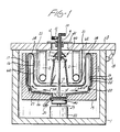
- FIGURE 1 a whole blood separation and irradiation device constructed in accordance with the principles of the present invention is shown.
- the device comprises a stationary housing 1 and cover 3 which encloses a rotatable separation/irradiation chamber 14.
- a light source in the form of five U-shaped U.V. bulbs 2.
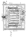
- the bulbs are arranged in a generally circular configuration around the inside of the separation/irradiation chamber of the device as shown in the plan cross-sectional view of FIGURE 2.
- the bulbs are shielded about their outer perimeter by a protective bulb cover 21, which also is attached to the cover 3.
- the stationary and rotatable sections of the device are joined by a rotary seal 60 at the axial center of the device.
- the rotary seal 60 includes an upper, nonrotating disk-shaped component 7 and a lower, rotating disk-shaped component 6.
- the nonrotating component 7 is attached to a central shaft 9 of the device by an elastic member 8.
- the central shaft passes through and is attached to the cover 3 by a clamp 31.
- the elastic member 8 urges the nonrotating component 7 downward so that the annular contacting surface of the component 7 is in contact with the upper surface of the rotating component 6 of the seal, thereby establishing a dynamic seal as the rotatable section of the device is rotated.
- the rotary seal is of the type described in U.S. Patent 4,300,717.
- a feed tube 13 Extending through the shaft 9 from above the cover 3 to the bottom of the separation/irradiation chamber is a feed tube 13. Axially extending from the shaft 9 is an air outlet port 11, the distal end of which is sealed with a microbial filter 12. Alternatively, the distal end of the air outlet port may be connected to a sterile empty bag. As the separation/irradiation chamber 14 is filled with whole blood, displaced air passes through the passageway between the feed tube 13 and the inner wall of the shaft 9. The air is then vented out through the filter 12 or into the empty bag.
- the distal end 10 of the feed tube 13 may be fitted with a connection to connect the tube to a blood supply line (not shown).
- the rotatable section of the device includes a continuously sealed separation/irradiation chamber 14 having a cylindrical outer compartment 62.
- the outer compartment 62 has an outer wall 17 and an inner wall 16 which opposes the light source 2.
- the inner wall 16 is made of a material transparent to a wavelength of the light source. For example, acrylic plastics, polyethylene, polypropylene, polyvinylchloride, pyrex glass, and silica are transparent to ultraviolet and visible light.
- the separation/irradiation chamber 14 is seated inside a chuck 19, and is sealed therein by an O-ring 20.
- the chuck 19 is connected by a coupling 40 to the shaft 39 of a motor 22 in the bottom of the housing that rotates the chuck at the desired speed.
- Centrifugal forces will thus be developed in the separation/irradiation chamber 14 and its outer compartment 62 as the chamber is rotated about the light source 2.
- the chamber 14 remains sealed during rotation by the rotary seal 60.
- a drain tube 30 allows drainage of cleaning and other fluids from the chuck 19 by opening a stopcock on the drain tube.
- the cover 3 is connected to the housing 1 by a hinge 18.
- the hinge desirably articulates so that when the clamp 31 is unclamped and opened about the shaft 9 the cover can be lifted and will clear the shaft 9 and the air outlet port 11 without interference.
- the motor is energized to rotate the separation/irradiation chamber 14 for the generation of centrifugal forces within the chamber.
- a desirable range of the centrifugal speed is 1000-6000 RPM.
- a blood supply line is connected to the distal end 10 of the feed tube 13 and whole blood treated with a photoactivatable compound and preferably an anticoagulant is supplied to the tube by a blood pump or gravity feed.
- the air displaced by the volume of blood is vented out through the air outlet port 11 and microbial filter 12 or into a sterile empty bag.
- the whole blood passes down the tube to the recessed blood collection well 15 at the bottom of the separation/irradiation chamber 14.
- the centrifugal forces of the rotating chamber push the blood out of the well 15 and up the sloped bottom 26 of the chamber to the outer compartment 62 of the chamber.
- a step 27 is formed at the junction of the bottom of the chamber and the outer compartment 62 whereby substantially all of the blood will be elevated above the bottom of the chamber and into the compartment 62 without contacting the inner wall 16 of the chamber.
- the rotating chamber forces the blood against the outer wall 17 of the separation/irradiation chamber where cell separation occurs in accordance with the sedimentation rates of individual blood components. This centrifugal separation will result in the development of a layer 25 of red blood cells in contact with the outer wall 17 of the chamber.
- the innermost separated layer comprises a plasma layer 23, and between the red blood cell layer and the plasma layer is a thin lymphocyte enriched layer 24, referred to herein as a buffy coat layer.
- a thin lymphocyte enriched layer 24, referred to herein as a buffy coat layer.
- red blood cells which would otherwise act to shield other blood components from U.V. light, are located outside the lymphocyte enriched buffy coat layer.
- the composition of whole blood, and hence the relative thicknesses of the separated layers, is approximately 45% red blood cells, 55% plasma, and 0.1% buffy coat.
- the sedimentation rate of lymphocytes is lower than that of other white blood cells in the buffy coat 24.
- the lymphocytes are highly concentrated in the side of the buffy coat which opposes the plasma layer 23.
- U.V. light from the light source 2 will therefore pass through the protective bulb cover 21, the inner wall 16 of the separation/irradiation chamber, and the plasma layer 23 to irradiate the lymphocytes in the buffy coat 24, a sequence shown in the view of FIGURE 2. Since the rotational forces in the chamber 14 will establish buffy coat and plasma layers of uniform thickness by reason of the vertical wall 17 of the chamber, the lymphocytes will be uniformly irradiated by the light source.
- the intensity and duration of irradiation exposure can be regulated to result in a controlled reaction of the lymphocytes to irradiation in combination with a photoactivatable compound.
- the motor 22 is turned off to stop the rotation of the separation/irradiation chamber 14.
- the separated blood components flow down from the outer compartment 62 of the chamber and down the sloped bottom 26 of the chamber, where they are remixed as they collect in the blood collection well 15.
- the blood is pumped out of the collection well through the feed tube 13 for return to the patient.
- the disposable components of the system which have come into contact with body fluids are removed and disposed of, including the separation/irradiation chamber 14, the dynamic seal, and the shaft 9 and attached components 10-13, which are unclamped from the cover 3.
- FIGURE 1 A constructed embodiment as described in FIGURE 1 has been built and tested using 250 ml. of whole blood and a rotational speed of 1650 RPM. It was found that, at a rotational speed of as low as 200 RPM, blood had begun to migrate up the outer wall of the separation/irradiation chamber under the influence of centrifugal force. After the separation and irradiation process was completed, it was found that the separated blood consitiuents remixed at the bottom of the chamber due to angular deceleration and pumping as the centrifuge slowed down and came to a stop.
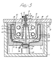
- FIGURE 3 illustrates a modified form of the embodiment of FIGURE 1, differing in that circular U.V. bulbs 2′ are used in place of the U-shaped bulbs of FIGURE 1. Like the embodiment of FIGURE 1, the circular bulbs 2′ are suitably attached to the underside of the cover 3, and are protected by the surrounding bulb cover 21 which is transparent to U.V. light.
- FIGURE 4 a second embodiment of a whole blood separation and irradiation device constructed in accordance with the principles of the present invention is shown.
- the stationary section of the device is substantially the same as described above, including the cover 3, the housing 1, the feed tube 13 affixed through the cover clamp 31, and the stationary component 7 of the seal with its elastic member 8.
- the rotatable component 6 of the rotary seal is clamped so as to enter a rotating fluid entry compartment 28 at the upper portion of the device.
- the feed tube 13 extends through the cover 3 to a point near the bottom of the fluid entry compartment.
- a support member 35 is attached between the fluid entry compartment 28 and an outer centrifuge drum 36 of the rotatable section of the device.
- the centrifuge drum 36 is seated in a rotating chuck 70.
- a groove 74 for a drive belt 38 is formed around the lower extension of the chuck 70.
- the drive belt 38 is located around the groove 74 and pulley 37 of the drive motor 22.
- the rotating chuck 70 rotates with respect to the housing by bearings 72 located between the chuck and the housing.
- U.V. bulbs 47 Located inside the centrifuge drum 36 is an array of five U-shaped U.V. bulbs 47.
- the bulbs 47 are mounted on a bulb mount 49 at the bottom of the device.
- the bulbs are surrounded by a protective bulb cover 48 which is transparent to U.V. light.
- the bulbs 47 are energized by a power source 76 located inside the housing.
- Blood is conducted from the fluid entry compartment 28 to a separation/irradiation chamber 29 by a radial feed tube 32.
- the feed tube 32 is continued downward through a passageway 33 of the separation/irradiation chamber 29 and terminates at a port 42 at the bottom of the chamber. While only a single radial feed tube is shown in the embodiment of FIGURE 4, it may be appreciated that a number of such tubes may radiate from the fluid entry compartment, or that blood may be conducted from the fluid entry compartment by a hollow disk-shaped member radiating outward from the fluid entry compartment. In such alternatives an array of vertical passageways would be used to conduct the blood to the bottom of the chamber 29.
- a cylindrical separation/irradiation chamber 29 Located inside the centrifuge drum 36 is a cylindrical separation/irradiation chamber 29, shown in an enlarged cross-section in FIGURE 6 and in FIGURE 5.
- the chamber 29 is connected to a rigid plastic or metal support plate 46 as its outer member.
- a number of locating pins 45 are a number of locating pins 45.
- the support plate 46 includes a passageway or passageways for passage of the vertical section 33 of the feed tube 32.
- the disposable chamber 29 is formed of two flexible polymeric sheets 51, 53 which are transparent to U.V. light and are heat or adhesively sealed about the periphery of sheet 51 as indicated at 43 to form a bag-like compartment.
- blood is supplied to the chamber at the inlet port 42 where the feed tube section 33 enters the chamber.
- the locating holes 44 are spaced around the periphery of the outer polymeric sheet 53.
- the flexible chamber is mounted in the centrifuge, it is covered around its inner surface by a cylindrical supporting wall 41, which is transparent to light at the critical wavelength and contains holes which align with the locating pins 45.
- the supporting wall 41 prevents the development of bulging at the bottom of the flexible chamber as the centrifuge slows down and blood accumulates at the bottom of the flexible compartment.
- the separation/irradiation chamber 29 and the supporting wall 41 are mounted inside the centrifuge drum 36 against the support plate 46 and the radial feed tube or tubes 32 are connected to the fluid entry compartment 28.
- the centrifuge drum and chuck are then rotated by the motor and its belt and pulley drive arrangement.
- the separation/irradiation chamber 29 is primed by pumping heparanized saline solution into the chamber as it rotates. After the chamber has been thoroughly primed with the solution the centrifuge is slowed to a rotational speed below 100 RPM (e.g., about 20 RPM) and the supply pump is reversed to pump the saline solution out of the separation/irradiation chamber. As the solution is pumped out the flexible chamber 29 collapses to its initial empty condition.
- the centrifuge is accelerated to its separation speed, e.g., on the order of 1000-6000 RPM, depending upon the diameter of the chamber.
- Whole blood is then pumped into the separation/irradiation chamber through the feed tube 13 leading to the fluid entry compartment 28.
- the centrifugal forces of the rotating fluid entry compartment push the blood outward through the radial feed tube 32 where it flows down the vertical tube portion at 33 and through the port 42 to the separation/irradiation chamber 29.
- the chamber 29 is initially collapsed as the flexible chamber is pressed against the support plate 46 due to centrifugal force, but the flow of blood will expand the flexible chamber toward the supporting wall 41 as blood fills the chamber.
- the rotating centrifuge drum is slowed down, preferably to a speed below 50 RPM.
- the separated blood begins to flow downward in the chamber under the influence of gravity and the flexible sheets of the chamber collapse as blood is pumped out of the chamber through the port 42 and tubes 13, 32 and 33.
- the flexible chamber is collapsed back to its initial position against the outer wall of the chamber.
- the disposable components are removed and disposed of after use, including the separation/irradiation chamber 29, tubes 13, 32, and 33, the compartment 28, and the dynamic seal.
- FIGURE 7 shows an alternate embodiment of the chamber 29 of FIGURES 4-6, in which the inner cylindrical surface of the chamber 29 is formed of a sheet 51 of flexible film which is sealed about its periphery 58 to a rigid support component 57, the latter functioning as both the outer wall of the separation/irradiation chamber and the support plate 46.
- the need for a separate support plate distinct from the separation/irradiation chamber is eliminated.
- Overlying the flexible film inner surface of the chamber in this embodiment is the inner cylindrical supporting wall 41 which is mounted on locating pins extending from the periphery of the inner surface of the chamber.
- Some of the polymeric material suitable for use as the support component 57, the supporting wall 41, and the flexible film 51 include polypropylene, polyethylene, ethylvinyl acetate, polyvinylchloride, and acrylic materials.
- FIGURE 8 A further embodiment of a separation/irradiation chamber 14′ suitable for use in the device of FIGURE 1 is shown in FIGURE 8. It has been found that occasional bubbling of the whole blood can cause small deposits of red blood cells to strike and adhere to the inner wall 16 of the separation/irradiation chamber 14 of FIGURE 1. These small deposits of red cells can retard the transmission of light from the bulbs 2 to the separated buffy coat layer 24.
- the separation/irradiation chamber 14′ of FIGURE 8 alleviates this condition by providing a volume between the chamber walls which is substantially entirely filled with a predetermined volume of blood.
- the separation/irradiation chamber 14′ of FIGURE 8 is approximately 4 inches in height and has a controlled spacing between the inner wall 16′ and the outer wall 17′ which can be filled as shown in FIGURE 8 by 250 ml. of blood.
- the space between the walls at the top of the chamber is approximately 2 mm, and at the center of the wall height the space is approximately 6 mm wide.
- This spacing is achieved by employing a vertical outer wall 17′ and an inwardly tapering inner wall 16′, which tapers away from the outer wall at an angle of approximately 2°-3°.
- the angular taper allows air in the chamber to be replaced by blood by migrating down the inner tapered wall and to the center of the chamber, where it is vented out through the shaft 9 and the air outlet port 11.
- the plasma layer will continually wash the inner wall 16′, causing any red blood cells at the inner wall surface to detach and migrate to the outer wall under the influence of centrifugal force.
- the separation/irradiation chamber of FIGURE 8 is slowed down after the separation and irradiation procedure, the inner wall of the chamber is again washed by the angular deceleration of the plasma layer as the separation/irradiation chamber comes to a stop.
Landscapes
- Health & Medical Sciences (AREA)
- Heart & Thoracic Surgery (AREA)
- Vascular Medicine (AREA)
- General Health & Medical Sciences (AREA)
- Veterinary Medicine (AREA)
- Anesthesiology (AREA)
- Biomedical Technology (AREA)
- Hematology (AREA)
- Life Sciences & Earth Sciences (AREA)
- Animal Behavior & Ethology (AREA)
- Cardiology (AREA)
- Public Health (AREA)
- Engineering & Computer Science (AREA)
- External Artificial Organs (AREA)
- Physical Water Treatments (AREA)
- Physical Or Chemical Processes And Apparatus (AREA)
- Centrifugal Separators (AREA)
- Cyclones (AREA)
- Medicines Containing Material From Animals Or Micro-Organisms (AREA)
- Compounds Of Unknown Constitution (AREA)
- Medicines That Contain Protein Lipid Enzymes And Other Medicines (AREA)
Abstract
Description
- This invention relates to systems for separating and irradiating multicomponent fluids and, in particular, to the use of such systems in the field of treating cells with photoactivatable compounds by radiation, which activates the compounds to effect cellular change.
- Numerous human disease states of the blood respond favorably to the treatment of selected blood components by visible or ultraviolet light irradiation. Such treatment may be effective to eliminate immunogenicity in cells, inactivate or kill selected cells, inactivate viruses or bacteria, or activate desirable immune responses. Certain forms of treatment with light irradiation may be effective without the introduction of outside agents or compounds, while others may involve the introduction of specific agents or catalysts. Among the latter treatment techniques is the use of photoactivatable agents to regulate the population of leukocytes. It is well-known that a number of human disease states may be characterized by the overproduction of certain types of leukocytes, including lymphocytes, in comparison to other populations of cells which normally comprise whole blood. Excessive or abnormal lymphocyte populations result in numerous adverse effects in patients including the functional impairment of bodily organs, leukocyte mediated autoimmune diseases and leukemia related disorders many of which often ultimately result in fatality.
- U.S. Patent Nos. 4,321,919; 4,398,906; 4,428,744; and 4,464,166 to Edelson describe methods for treating blood whereby the operation or viability of certain cellular populations may be moderated thereby providing relief for these patients. In general, the methods comprise treating the blood with a dissolved photoactivatable drug, such as psoralen, which is capable of forming photoadducts with DNA in the presence of ultraviolet (U.V.) radiation. It is believed that covalent bonding results between the psoralen and the lymphocyte nucleic acid thereby effecting metabolic inhibition of the treated cells. Following extracorporeal irradiation, the cells are returned to the patient where they are thought to be cleared by natural processes but at an accelerated pace believed attributable to disruption of membrane integrity, alteration of DNA within the cell, or like conditions often associated with substantial loss of cellular effectiveness or viability.
- Although a number of photoactivatable compounds in the psoralen class are known, 8-methoxy psoralen is presently the compound of choice. An effective radiation for this compound, and many psoralens in general, is the ultraviolet spectrum in the range of approximately 320 to 400 nanometers, alternatively referred to as the U.V.A. spectrum. As the development of photoactivatable compounds proceeds, it may be expected that changes in the preferred activation radiation spectrum may occur. For instance, it may be preferable to treat some disease states with light in the ultraviolet spectrum of 280 to 320 nanometers, referred to as the U.V.B. spectrum. Suitable selection of radiation sources may be expected to increase treatment efficiency and is contemplated as an obvious optimization procedure for use with the invention disclosed herein.
- In initial implementations of the Edelson methods whole blood was treated in vitro using devices such as flasks, filtration columns, spectrophotometer cuvettes, and petri dishes. The blood sample to be irradiated was added to the containers and the containers placed adjacent to the radiation source. Such systems were characterized by difficulty in providing the necessary safeguards intrinsically necessary where patient bodily fluids are concerned, particularly since these fluids must be returned to the patient, thereby necessitating strict avoidance of contamination. Further, such methods tend to be volume limited, are characterized by many mechanical manipulations and are generally unacceptable from a clinical and regulatory viewpoint.
- United States patent no. 4,573,960 describes an advance made in these initial implementation techniques by Taylor. Taylor describes a practical device for coupling the radiation provided by commercially available light sources, such as so-called "black-light" fluorescent tubes, to cells for treatment by Edelson's photoactivated drug methods. In summary, the disposable cassette described by Taylor comprises a plurality of fluorescent tube-like light sources such as the U.V.A. emitting Sylvania F8T5/BLB bulb, which are individually, coaxially mounted in tubes of larger diameter which are, in turn, coaxially mounted in sealing arrangement within second outer tubes of even larger diameter, thereby forming a structure having two generally elongated, cylindrical cavities about each radiation source. The inner cavity preferably communicates with the atmosphere thereby facilitating cooling of the radiation source. The second tube forming the outer cavity further comprises inlet and outlet means for receiving and discharging, respectively, the cells to be irradiated. A plurality of these structures are serially interconnected between inlets and outlets of adjacent members to provide for serpentine flow of cells through each outer cavity. Thus, continuous flow of the cells through the plurality of cavities surrounding the centrally disposed radiation sources facilitates thorough treatment of the cells.
- To be fully practical, however, the Taylor device requires a clinically acceptable instrument to house the device and to provide the cells to be treated in an appropriate form. Such an instrument and a method for its use are described in the aforementioned U.S. Patent 4,573,960. The method there described for extracorporeally photoactivating a photoactivatable reagent in contact with blood cells comprises the steps of collecting and separating on a continuous basis blood from a patient while the patient is connected to the instrument, returning undesired blood portions obtained during separation, and disconnecting the patient from the treatment system while the desired portion is photoactivatably treated, whereafter the treated cells are returned to the patient. Thus, the instrument and method of this patent broadly maximizes a patient's safety and optimizes the various aspects of such photoactivation treatment by breaking the entire procedure down into three phases or modes. In the first mode the instrument collects and separates blood on a continuous basis as it is withdrawn from the patient and returns unwanted portions to the patient, all of which are accomplished while the patient remains connected to the apparatus. Thereafter, prior to energizing the irradiation sources for photoactivating the photoactivatable reagent in contact with the desired blood portion, the patient may be disconnected from the instrument while irradiation and photoactivation are performed on the separated component of the blood during the second mode. Following photoactivation the treated cells may then be facilely returned to the patient during a third mode, utilizing a variety of techniques, the preferred being a simple drip chamber gravity feed infusion line.
- While the foregoing instrument and method provide a system which has met clinical and regulatory standards, it is desirable to provide the system with even greater clinical and operational efficiency. It would be desirable, for instance, to combine the first and second modes of the prior method, whereby the desired blood component is photoactivatably treated during separation of the blood components. While improving efficiency and reducing system complexity, such an improvement would also eliminate the blood tubing set, valves, container, and tubular or flat plate cassettes required for the separate irradiation mode of operation in the prior apparatus described in the aforementioned U.S. Patent 4,573,960 and in U.S. Patent 4,737,140 (Lee et al.). In such an improved arrangement, the dynamic operating variables of the separation process could be used to controllably irradiate the desired blood component while minimizing unnecessary irradiation of other components of the blood.
- Furthermore, the necessary remixing of the separated blood components may be performed at the conclusion of the irradiation treatment by the same apparatus that initially separates the blood components, thereby obviating the intervening step of returning only unwanted components to the patient.
- DE-A-2745041 describes and illustrates a plasmaphoresis device according to the preamble of
claim 1. The device uses centrifugal forces for separating patient whole blood into various layers containing red blood cells or plasma or lymphocytes. After separation the plasma layer is removed and the remaining parts are returned to the patient. - FR-A-1233327 describes and illustrates a device for extracorporeal enrichment of blood with a mixture of oxygen. Ozone used by this device is produced in situ by irradiation of oxygen in the same device. The wall of the irradiation chamber surrounding the source of radiation may be transmissive at least for particular wavelengths. Unspecific simultaneous irradiation of all blood components can occur to amend blood quality.
- In accordance with the principles of the present invention, a multicomponent fluid separation and irradiation apparatus is provided which may be advantageously utilized to separate and irradiate desired components of blood. The apparatus includes a housing;
a rotatable member located within said housing;
a disposable separation/irradiation chamber adapted to be mounted in said rotatable member and including a vertical cylindrical outer compartment in fluid communication with an inner compartment extending between said outer compartment and the center of said chamber, and a first passageway accessing said inner compartment; and
a dynamic seal having a rotatable member and a stationary member, said rotatable member being connected to said inner compartment of said chamber, and said first passageway passing through said dynamic seal; and characterised by
a source of radiant energy of a given wavelength connected to said housing and located radially within said separation/irradiation chamber so as to oppose the inner wall of said outer compartment, wherein said inner wall of said outer compartment is transmissive of radiant energy of said given wavelength. - In the drawings:
- FIGURE 1 illustrates in a partially cross-sectional view a first embodiment of a multicomponent fluid separation and irradiation system constructed in accordance with the principles of the present invention;
- FIGURE 2 is a plan cross-sectional view of the system of FIGURE 1;
- FIGURE 3 is an alternate embodiment of the system of FIGURE 1 utilizing a circular tube light source;
- FIGURE 4 illustrates a cross-sectional view of a second multicomponent fluid separation and irradiation system constructed in accordance with the principles of the present invention;
- FIGURE 5 is an elevational view of the fluid separation compartment of the embodiment of FIGURE 4;
- FIGURE 6 is an enlarged cross-sectional view of the fluid separation compartment of the embodiment of FIGURE 4;
- FIGURE 7 is an enlarged cross-sectional view of an alternate embodiment of the fluid separation compartment of the embodiment of FIGURE 4; and
- FIGURE 8 is a cross-sectional view of a fluid separation compartment which is filled with a predetermined quantity of blood.
- Referring first to FIGURE 1, a whole blood separation and irradiation device constructed in accordance with the principles of the present invention is shown. The device comprises a
stationary housing 1 and cover 3 which encloses a rotatable separation/irradiation chamber 14. Depending from the stationary centrifuge cover is a light source in the form of five U-shaped U.V.bulbs 2. The bulbs are arranged in a generally circular configuration around the inside of the separation/irradiation chamber of the device as shown in the plan cross-sectional view of FIGURE 2. The bulbs are shielded about their outer perimeter by aprotective bulb cover 21, which also is attached to the cover 3. - The stationary and rotatable sections of the device are joined by a
rotary seal 60 at the axial center of the device. Therotary seal 60 includes an upper, nonrotating disk-shaped component 7 and a lower, rotating disk-shaped component 6. The nonrotating component 7 is attached to acentral shaft 9 of the device by anelastic member 8. The central shaft in turn passes through and is attached to the cover 3 by aclamp 31. Theelastic member 8 urges the nonrotating component 7 downward so that the annular contacting surface of the component 7 is in contact with the upper surface of the rotating component 6 of the seal, thereby establishing a dynamic seal as the rotatable section of the device is rotated. The rotary seal is of the type described in U.S. Patent 4,300,717. - Extending through the
shaft 9 from above the cover 3 to the bottom of the separation/irradiation chamber is afeed tube 13. Axially extending from theshaft 9 is an air outlet port 11, the distal end of which is sealed with a microbial filter 12. Alternatively, the distal end of the air outlet port may be connected to a sterile empty bag. As the separation/irradiation chamber 14 is filled with whole blood, displaced air passes through the passageway between thefeed tube 13 and the inner wall of theshaft 9. The air is then vented out through the filter 12 or into the empty bag. Thedistal end 10 of thefeed tube 13 may be fitted with a connection to connect the tube to a blood supply line (not shown). - The rotatable section of the device includes a continuously sealed separation/
irradiation chamber 14 having a cylindricalouter compartment 62. Theouter compartment 62 has anouter wall 17 and aninner wall 16 which opposes thelight source 2. Theinner wall 16 is made of a material transparent to a wavelength of the light source. For example, acrylic plastics, polyethylene, polypropylene, polyvinylchloride, pyrex glass, and silica are transparent to ultraviolet and visible light. The separation/irradiation chamber 14 is seated inside achuck 19, and is sealed therein by an O-ring 20. Thechuck 19 is connected by acoupling 40 to theshaft 39 of amotor 22 in the bottom of the housing that rotates the chuck at the desired speed. Centrifugal forces will thus be developed in the separation/irradiation chamber 14 and itsouter compartment 62 as the chamber is rotated about thelight source 2. Thechamber 14 remains sealed during rotation by therotary seal 60. Adrain tube 30 allows drainage of cleaning and other fluids from thechuck 19 by opening a stopcock on the drain tube. - The cover 3 is connected to the
housing 1 by ahinge 18. The hinge desirably articulates so that when theclamp 31 is unclamped and opened about theshaft 9 the cover can be lifted and will clear theshaft 9 and the air outlet port 11 without interference. - In operation, the motor is energized to rotate the separation/
irradiation chamber 14 for the generation of centrifugal forces within the chamber. A desirable range of the centrifugal speed is 1000-6000 RPM. A blood supply line is connected to thedistal end 10 of thefeed tube 13 and whole blood treated with a photoactivatable compound and preferably an anticoagulant is supplied to the tube by a blood pump or gravity feed. As the blood enters the system the air displaced by the volume of blood is vented out through the air outlet port 11 and microbial filter 12 or into a sterile empty bag. The whole blood passes down the tube to the recessed blood collection well 15 at the bottom of the separation/irradiation chamber 14. The centrifugal forces of the rotating chamber push the blood out of the well 15 and up the slopedbottom 26 of the chamber to theouter compartment 62 of the chamber. Astep 27 is formed at the junction of the bottom of the chamber and theouter compartment 62 whereby substantially all of the blood will be elevated above the bottom of the chamber and into thecompartment 62 without contacting theinner wall 16 of the chamber. The rotating chamber forces the blood against theouter wall 17 of the separation/irradiation chamber where cell separation occurs in accordance with the sedimentation rates of individual blood components. This centrifugal separation will result in the development of alayer 25 of red blood cells in contact with theouter wall 17 of the chamber. The innermost separated layer comprises aplasma layer 23, and between the red blood cell layer and the plasma layer is a thin lymphocyte enrichedlayer 24, referred to herein as a buffy coat layer. Thus the red blood cells, which would otherwise act to shield other blood components from U.V. light, are located outside the lymphocyte enriched buffy coat layer. The composition of whole blood, and hence the relative thicknesses of the separated layers, is approximately 45% red blood cells, 55% plasma, and 0.1% buffy coat. - The sedimentation rate of lymphocytes is lower than that of other white blood cells in the
buffy coat 24. Thus, the lymphocytes are highly concentrated in the side of the buffy coat which opposes theplasma layer 23. U.V. light from thelight source 2 will therefore pass through theprotective bulb cover 21, theinner wall 16 of the separation/irradiation chamber, and theplasma layer 23 to irradiate the lymphocytes in thebuffy coat 24, a sequence shown in the view of FIGURE 2. Since the rotational forces in thechamber 14 will establish buffy coat and plasma layers of uniform thickness by reason of thevertical wall 17 of the chamber, the lymphocytes will be uniformly irradiated by the light source. By measuring the ratios of the components of the whole blood and the volume of blood supplied to the separation/irradiation chamber, the intensity and duration of irradiation exposure can be regulated to result in a controlled reaction of the lymphocytes to irradiation in combination with a photoactivatable compound. - At the end of the desired period of irradiation the
motor 22 is turned off to stop the rotation of the separation/irradiation chamber 14. The separated blood components flow down from theouter compartment 62 of the chamber and down the slopedbottom 26 of the chamber, where they are remixed as they collect in the blood collection well 15. The blood is pumped out of the collection well through thefeed tube 13 for return to the patient. The disposable components of the system which have come into contact with body fluids are removed and disposed of, including the separation/irradiation chamber 14, the dynamic seal, and theshaft 9 and attached components 10-13, which are unclamped from the cover 3. - A constructed embodiment as described in FIGURE 1 has been built and tested using 250 ml. of whole blood and a rotational speed of 1650 RPM. It was found that, at a rotational speed of as low as 200 RPM, blood had begun to migrate up the outer wall of the separation/irradiation chamber under the influence of centrifugal force. After the separation and irradiation process was completed, it was found that the separated blood consitiuents remixed at the bottom of the chamber due to angular deceleration and pumping as the centrifuge slowed down and came to a stop.
- FIGURE 3 illustrates a modified form of the embodiment of FIGURE 1, differing in that circular U.V.
bulbs 2′ are used in place of the U-shaped bulbs of FIGURE 1. Like the embodiment of FIGURE 1, thecircular bulbs 2′ are suitably attached to the underside of the cover 3, and are protected by the surroundingbulb cover 21 which is transparent to U.V. light. - Referring now to FIGURE 4, a second embodiment of a whole blood separation and irradiation device constructed in accordance with the principles of the present invention is shown. In this embodiment the stationary section of the device is substantially the same as described above, including the cover 3, the
housing 1, thefeed tube 13 affixed through thecover clamp 31, and the stationary component 7 of the seal with itselastic member 8. Unlike the previous embodiment, the rotatable component 6 of the rotary seal is clamped so as to enter a rotatingfluid entry compartment 28 at the upper portion of the device. Thefeed tube 13 extends through the cover 3 to a point near the bottom of the fluid entry compartment. Asupport member 35 is attached between thefluid entry compartment 28 and anouter centrifuge drum 36 of the rotatable section of the device. Thecentrifuge drum 36 is seated in arotating chuck 70. Agroove 74 for adrive belt 38 is formed around the lower extension of thechuck 70. Thedrive belt 38 is located around thegroove 74 andpulley 37 of thedrive motor 22. Therotating chuck 70 rotates with respect to the housing bybearings 72 located between the chuck and the housing. - Located inside the
centrifuge drum 36 is an array of five U-shaped U.V.bulbs 47. Thebulbs 47 are mounted on abulb mount 49 at the bottom of the device. The bulbs are surrounded by aprotective bulb cover 48 which is transparent to U.V. light. Thebulbs 47 are energized by apower source 76 located inside the housing. - Blood is conducted from the
fluid entry compartment 28 to a separation/irradiation chamber 29 by aradial feed tube 32. Thefeed tube 32 is continued downward through apassageway 33 of the separation/irradiation chamber 29 and terminates at aport 42 at the bottom of the chamber. While only a single radial feed tube is shown in the embodiment of FIGURE 4, it may be appreciated that a number of such tubes may radiate from the fluid entry compartment, or that blood may be conducted from the fluid entry compartment by a hollow disk-shaped member radiating outward from the fluid entry compartment. In such alternatives an array of vertical passageways would be used to conduct the blood to the bottom of thechamber 29. - Located inside the
centrifuge drum 36 is a cylindrical separation/irradiation chamber 29, shown in an enlarged cross-section in FIGURE 6 and in FIGURE 5. In the latter FIGURE the cylindrical chamber has been "unrolled" to a flat shape for clarity of illustration. Thechamber 29 is connected to a rigid plastic ormetal support plate 46 as its outer member. Around the periphery of the support plate are a number of locating pins 45. When thechamber 29 is mounted inside thecentrifuge drum 36, locatingholes 44 of the chamber fit over the matching locating pins 45. Thesupport plate 46 includes a passageway or passageways for passage of thevertical section 33 of thefeed tube 32. - The
disposable chamber 29 is formed of twoflexible polymeric sheets sheet 51 as indicated at 43 to form a bag-like compartment. As shown in FIGURE 5, blood is supplied to the chamber at theinlet port 42 where thefeed tube section 33 enters the chamber. The locating holes 44 are spaced around the periphery of theouter polymeric sheet 53. When the flexible chamber is mounted in the centrifuge, it is covered around its inner surface by acylindrical supporting wall 41, which is transparent to light at the critical wavelength and contains holes which align with the locating pins 45. The supportingwall 41 prevents the development of bulging at the bottom of the flexible chamber as the centrifuge slows down and blood accumulates at the bottom of the flexible compartment. - In operation the separation/
irradiation chamber 29 and the supportingwall 41 are mounted inside thecentrifuge drum 36 against thesupport plate 46 and the radial feed tube ortubes 32 are connected to thefluid entry compartment 28. The centrifuge drum and chuck are then rotated by the motor and its belt and pulley drive arrangement. The separation/irradiation chamber 29 is primed by pumping heparanized saline solution into the chamber as it rotates. After the chamber has been thoroughly primed with the solution the centrifuge is slowed to a rotational speed below 100 RPM (e.g., about 20 RPM) and the supply pump is reversed to pump the saline solution out of the separation/irradiation chamber. As the solution is pumped out theflexible chamber 29 collapses to its initial empty condition. - Following the priming procedure the centrifuge is accelerated to its separation speed, e.g., on the order of 1000-6000 RPM, depending upon the diameter of the chamber. Whole blood is then pumped into the separation/irradiation chamber through the
feed tube 13 leading to thefluid entry compartment 28. The centrifugal forces of the rotating fluid entry compartment push the blood outward through theradial feed tube 32 where it flows down the vertical tube portion at 33 and through theport 42 to the separation/irradiation chamber 29. Thechamber 29 is initially collapsed as the flexible chamber is pressed against thesupport plate 46 due to centrifugal force, but the flow of blood will expand the flexible chamber toward the supportingwall 41 as blood fills the chamber. The whole blood then becomes distributed in layers, as described above, against the outer wall of the rotating separation/irradiation chamber 29. U.V. light from thelight source 47 will pass through theprotective bulb cover 48, the supportingwall 41, theinner chamber sheet 51, and theinner plasma layer 23 to reach the lymphocytes in thebuffy coat layer 24, shown most clearly in FIGURE 6. - When the desired irradiation period has ended, the rotating centrifuge drum is slowed down, preferably to a speed below 50 RPM. The separated blood begins to flow downward in the chamber under the influence of gravity and the flexible sheets of the chamber collapse as blood is pumped out of the chamber through the
port 42 andtubes irradiation chamber 29,tubes compartment 28, and the dynamic seal. - FIGURE 7 shows an alternate embodiment of the
chamber 29 of FIGURES 4-6, in which the inner cylindrical surface of thechamber 29 is formed of asheet 51 of flexible film which is sealed about itsperiphery 58 to arigid support component 57, the latter functioning as both the outer wall of the separation/irradiation chamber and thesupport plate 46. In this embodiment the need for a separate support plate distinct from the separation/irradiation chamber is eliminated. Overlying the flexible film inner surface of the chamber in this embodiment is the innercylindrical supporting wall 41 which is mounted on locating pins extending from the periphery of the inner surface of the chamber. Some of the polymeric material suitable for use as thesupport component 57, the supportingwall 41, and theflexible film 51 include polypropylene, polyethylene, ethylvinyl acetate, polyvinylchloride, and acrylic materials. - A further embodiment of a separation/
irradiation chamber 14′ suitable for use in the device of FIGURE 1 is shown in FIGURE 8. It has been found that occasional bubbling of the whole blood can cause small deposits of red blood cells to strike and adhere to theinner wall 16 of the separation/irradiation chamber 14 of FIGURE 1. These small deposits of red cells can retard the transmission of light from thebulbs 2 to the separatedbuffy coat layer 24. The separation/irradiation chamber 14′ of FIGURE 8 alleviates this condition by providing a volume between the chamber walls which is substantially entirely filled with a predetermined volume of blood. The separation/irradiation chamber 14′ of FIGURE 8 is approximately 4 inches in height and has a controlled spacing between theinner wall 16′ and theouter wall 17′ which can be filled as shown in FIGURE 8 by 250 ml. of blood. The space between the walls at the top of the chamber is approximately 2 mm, and at the center of the wall height the space is approximately 6 mm wide. This spacing is achieved by employing a verticalouter wall 17′ and an inwardly taperinginner wall 16′, which tapers away from the outer wall at an angle of approximately 2°-3°. The angular taper allows air in the chamber to be replaced by blood by migrating down the inner tapered wall and to the center of the chamber, where it is vented out through theshaft 9 and the air outlet port 11. As the separating blood fills the volume of the separation/irradiation chamber 14′, the plasma layer will continually wash theinner wall 16′, causing any red blood cells at the inner wall surface to detach and migrate to the outer wall under the influence of centrifugal force. Thus, there is no air gap between theinner wall 16′ and theplasma layer 23, which eliminates irradiation losses due to the passage of light through the air gap and reflective losses at the surface of the plasma layer. As the separation/irradiation chamber of FIGURE 8 is slowed down after the separation and irradiation procedure, the inner wall of the chamber is again washed by the angular deceleration of the plasma layer as the separation/irradiation chamber comes to a stop.
Claims (25)
- Apparatus for separating and irradiating blood comprising:
a housing (1);
a rotatable member (19; 70) located within said housing (1);
a disposable separation/irradiation chamber (14; 29, 40) adapted to be mounted in said rotatable member (19; 70) and including a vertical cylindrical outer compartment (62; 29) in fluid communication with an inner compartment extending between said outer compartment (62; 29) and the center of said chamber (14; 29, 40), and a first passageway (13) accessing said inner compartment; and
a dynamic seal (60) having a rotatable member (6) and a stationary member (7), said rotatable member (6) being connected to said inner compartment of said chamber (14; 29, 40), and said first passageway (13) passing through said dynamic seal (60); and characterised by
a source (2, 21; 47) of radiant energy of a given wavelength connected to said housing (1) and located radially within said separation/irradiation chamber (14; 29, 40) so as to oppose the inner wall (16; 51) of said outer compartment (62; 29), wherein said inner wall (16; 51) of said outer compartment (62; 29) is transmissive of radiant energy of said given wavelength. - The apparatus of claim 1, wherein said inner compartment of said separation/irradiation chamber (14) extends inwardly from the bottom of said outer compartment and said first passageway (13) is connected at the center of said inner compartment.
- The apparatus of claim 2, wherein said separation/irradiation chamber (14) further includes a central compartment extending upward and in fluid communication with said inner compartment, said dynamic seal (60) is connected to said central compartment, and said source (2, 21) of radiant energy is located between said central compartment and said inner wall (16) of said outer compartment (62).
- The apparatus of claim 3, wherein said first passageway (13) extends through said central compartment to a point near the bottom of said inner compartment.
- The apparatus of claim 4, further comprising a second passageway (11) accessing said separation/irradiation chamber (14) and extending through said dynamic seal (60) for the passage of air out of said separation/irradiation chamber (14).
- The apparatus of claim 5, wherein said first (13) and second (11) passageways pass concentrically through said dynamic seal (60).
- The apparatus of claim 2, wherein said separation/irradiation chamber (14) further includes a radial step (27) located at the lower junction of said inner and outer compartment surfaces.
- The apparatus of claim 2, wherein said inner compartment includes a bottom floor (26) which is sloped toward the center of said chamber.
- The apparatus of claim 8, wherein said inner compartment further includes a collection well (15) located at the center of said floor (26), said collection well (15) being accessed by said first passageway (13).
- The apparatus of claim 2, wherein said radiant energy source (21) comprises a plurality of circular shaped bulbs (21) arranged in a vertical pattern in opposition to the inner wall (16) of said outer compartment (62).
- The apparatus of claim 1, wherein said inner compartment comprises:
a fluid entry compartment (40) attached to said rotatable member (6); and
conduit means (32) for fluidly connecting said fluid entry compartment (40) and said outer compartment (29). - The apparatus of claim 11, wherein said outer compartment (29) is collapsible.
- The apparatus of claim 11, wherein said fluid entry compartment (40) is located at the top of said separation/irradiation chamber (29, 40).
- The apparatus of claim 13, wherein said conduit means (32) is connected between said fluid entry compartment (40) and a point (42) near the bottom of said outer compartment (29).
- The apparatus of claim 12, further comprising a rigid cylindrical member (41) adapted to be mounted inside said rotatable member (70) to retain said collapsible outer compartment (29) between said rotatable member (70) and said rigid cylindrical member (41).
- The apparatus of claim 5 or 11, wherein said housing (1) includes an aperture passing therethrough, and further including:
means (31) for attaching said first passageway (13) and said stationary member (7) of said dynamic seal (60) to said housing (1), whereby said passageway (13) passes through said aperture. - The apparatus of claim 16, wherein said housing (1) includes a housing cover (3) containing said aperture and means (31) for detachably affixing said passageway (13) in said aperture.
- The apparatus of claim 3 or 17, further including a shield (21; 48) attached to said housing (1) which is transmissive of radiant energy at said given wavelength and is located between said source (2, 21; 47) and said outer compartment (62; 29)
- The apparatus of claim 2 or 18, wherein said radiant energy source (2; 47) comprises a plurality of U-shaped bulbs (2; 47) arranged in a circular pattern in opposition to the inner wall (16; 51) of said outer compartment (62; 29).
- Apparatus according to claim 12, wherein said separation/irradiation chamber (40, 29) comprises first (51) and second (53) flexible sheets, at least one (51) of which is transparent to said radiant energy, said sheets (51, 53) being bonded together to form an interior compartment (29), said interior compartment (29) being connected to said first passageway (13), and including means for mounting said compartment-forming sheets (51, 53) within said rotatable member (70) with said transparent sheet (51) opposing said energy source.
- Apparatus according to claim 12, wherein said separation/irradiation chamber (40, 29) comprises:
a rigid outer cylindrical member (46); and
a sheet of flexible material (51) which is transparent to said radiant energy, said sheet being peripherally bonded inside said outer cylindrical member (46) to form a compartment (29) with a flexible inner wall. - The apparatus of claim 20 or 21, further including a rigid cylindrical member (41) mounted within said rotatable member (70) for retaining said separation/irradiation chamber (40, 29) between said rotatable member (70) and said rigid cylindrical member (41), wherein said rigid cylindrical member (41) is transmissive of said radiant energy.
- The apparatus of claim 20 or 22, including a fluid entry passageway (32) connected near the bottom of said compartment (29).
- The apparatus of claim 23, wherein said passageway (32) accesses said compartment (29) through said outer cylindrical member (46).
- The apparatus of claim 22, comprising a plurality of pins (45) located about the periphery of said rotatable member (70), a plurality of holes located about the periphery of said interior compartment (29) which align with said pins, and wherein said rigid cylindrical member (41) includes a plurality of holes located about its periphery which align with said pins.
Applications Claiming Priority (2)
| Application Number | Priority Date | Filing Date | Title |
|---|---|---|---|
| US305339 | 1989-02-02 | ||
| US07/305,339 US4921473A (en) | 1989-02-02 | 1989-02-02 | Multicomponent fluid separation and irradiation system |
Publications (3)
| Publication Number | Publication Date |
|---|---|
| EP0381528A2 EP0381528A2 (en) | 1990-08-08 |
| EP0381528A3 EP0381528A3 (en) | 1990-12-05 |
| EP0381528B1 true EP0381528B1 (en) | 1994-05-18 |
Family
ID=23180396
Family Applications (1)
| Application Number | Title | Priority Date | Filing Date |
|---|---|---|---|
| EP90301139A Expired - Lifetime EP0381528B1 (en) | 1989-02-02 | 1990-02-02 | Multicomponent fluid separation and irradiation system |
Country Status (11)
| Country | Link |
|---|---|
| US (1) | US4921473A (en) |
| EP (1) | EP0381528B1 (en) |
| JP (1) | JP2825588B2 (en) |
| KR (1) | KR0137934B1 (en) |
| AT (1) | ATE105716T1 (en) |
| CA (1) | CA2009124C (en) |
| DE (1) | DE69008879T2 (en) |
| ES (1) | ES2053097T3 (en) |
| GR (1) | GR1000725B (en) |
| HK (1) | HK119294A (en) |
| MX (1) | MX171686B (en) |
Families Citing this family (56)
| Publication number | Priority date | Publication date | Assignee | Title |
|---|---|---|---|---|
| ZA919934B (en) * | 1990-12-20 | 1992-09-30 | Baxter Int | Systems and methods for eradicating contaminants using photoactive materials in fluids like blood using discrete sources of radiation |
| WO1992011060A1 (en) * | 1990-12-20 | 1992-07-09 | Baxter International Inc. | Systems for eradicating contaminants in fluids |
| JP3051998B2 (en) * | 1990-12-20 | 2000-06-12 | バクスター、インターナショナル、インコーポレイテッド | System and method for simultaneous removal of free and entrained contaminants in liquids such as blood using photoactive therapy and cell separation techniques |
| JP3051997B2 (en) * | 1990-12-20 | 2000-06-12 | バクスター、インターナショナル、インコーポレイテッド | System and method for eradicating contaminants in liquids |
| US5308309A (en) * | 1992-12-23 | 1994-05-03 | Therakos, Inc. | Securing system for centrifuge chamber |
| US5362300A (en) * | 1993-05-27 | 1994-11-08 | E. I. Du Pont De Nemours And Company | Shell-type centrifuge rotor |
| US5569928A (en) * | 1993-12-14 | 1996-10-29 | Therakos, Inc | Photoactivation light array |
| US5527704A (en) | 1994-12-06 | 1996-06-18 | Baxter International Inc. | Apparatus and method for inactivating viral contaminants in body fluids |
| FR2730166B1 (en) * | 1995-02-08 | 1997-10-31 | Stas Sa | AEROSOL GENERATOR WITH MEANS OF STERILIZATION |
| CA2250919C (en) * | 1996-03-29 | 2008-05-13 | Therakos, Inc. | Photopheresis treatment of leukocytes |
| AU714882B2 (en) | 1996-04-09 | 2000-01-13 | Therakos, Inc. | Method for removal of psoralens from biological fluids |
| US5922278A (en) * | 1996-11-19 | 1999-07-13 | Baxter International Inc. | Method and apparatus for inactivating contaminants in biological fluid |
| US6190609B1 (en) | 1996-11-19 | 2001-02-20 | Baxter International Inc. | Methods and apparatus for inactivating contaminants in biological fluid |
| HUP0004089A2 (en) * | 1997-07-10 | 2001-04-28 | Therakos, Inc. | Treatment of inflammatory disorders of the bowel and bladder with extracorporeal photopheresis |
| US7049110B2 (en) * | 1998-07-21 | 2006-05-23 | Gambro, Inc. | Inactivation of West Nile virus and malaria using photosensitizers |
| US6258577B1 (en) | 1998-07-21 | 2001-07-10 | Gambro, Inc. | Method and apparatus for inactivation of biological contaminants using endogenous alloxazine or isoalloxazine photosensitizers |
| US7498156B2 (en) * | 1998-07-21 | 2009-03-03 | Caridianbct Biotechnologies, Llc | Use of visible light at wavelengths of 500 to 550 nm to reduce the number of pathogens in blood and blood components |
| US20030215784A1 (en) * | 1998-07-21 | 2003-11-20 | Dumont Larry Joe | Method and apparatus for inactivation of biological contaminants using photosensitizers |
| US6277337B1 (en) | 1998-07-21 | 2001-08-21 | Gambro, Inc. | Method and apparatus for inactivation of biological contaminants using photosensitizers |
| US7068361B2 (en) | 1999-06-03 | 2006-06-27 | Baxter International | Apparatus, systems and methods for processing and treating a biological fluid with light |
| US6565802B1 (en) | 1999-06-03 | 2003-05-20 | Baxter International Inc. | Apparatus, systems and methods for processing and treating a biological fluid with light |
| US7025877B1 (en) | 1999-06-03 | 2006-04-11 | Baxter International Inc. | Processing set for processing and treating a biological fluid |
| US7445756B2 (en) * | 1999-06-03 | 2008-11-04 | Fenwal, Inc. | Fluid processing sets and organizers for the same |
| US6471392B1 (en) | 2001-03-07 | 2002-10-29 | Holl Technologies Company | Methods and apparatus for materials processing |
| US6723999B2 (en) * | 1999-07-02 | 2004-04-20 | Holl Technologies Company | Electromagnetic wave assisted chemical processing |
| US6742774B2 (en) * | 1999-07-02 | 2004-06-01 | Holl Technologies Company | Process for high shear gas-liquid reactions |
| US7538237B2 (en) * | 1999-07-02 | 2009-05-26 | Kreido Laboratories | Process for high shear gas-liquid reactions |
| US6219584B1 (en) | 1999-07-09 | 2001-04-17 | Therakos, Inc. | Method and system for determining an effective amount of light energy to delivery to fluids having targets for the light energy |
| US7094378B1 (en) | 2000-06-15 | 2006-08-22 | Gambro, Inc. | Method and apparatus for inactivation of biological contaminants using photosensitizers |
| US7220747B2 (en) | 1999-07-20 | 2007-05-22 | Gambro, Inc. | Method for preventing damage to or rejuvenating a cellular blood component using mitochondrial enhancer |
| US8722422B2 (en) | 1999-09-03 | 2014-05-13 | Therakos, Inc. | Uninterrupted flow pump apparatus and method |
| US6495366B1 (en) * | 1999-09-03 | 2002-12-17 | Therakos, Inc. | Uninterrupted flow pump apparatus and method |
| US6268120B1 (en) | 1999-10-19 | 2001-07-31 | Gambro, Inc. | Isoalloxazine derivatives to neutralize biological contaminants |
| US6793643B1 (en) | 2000-04-21 | 2004-09-21 | Therakos, Inc. | Low extracorporeal volume treatment system |
| TW590780B (en) | 2000-06-02 | 2004-06-11 | Gambro Inc | Additive solutions containing riboflavin |
| US7648699B2 (en) | 2000-06-02 | 2010-01-19 | Caridianbct Biotechnologies, Llc | Preventing transfusion related complications in a recipient of a blood transfusion |
| US7985588B2 (en) | 2000-06-02 | 2011-07-26 | Caridianbct Biotechnologies, Llc | Induction of and maintenance of nucleic acid damage in pathogens using riboflavin and light |
| US9044523B2 (en) | 2000-06-15 | 2015-06-02 | Terumo Bct, Inc. | Reduction of contaminants in blood and blood products using photosensitizers and peak wavelengths of light |
| US6843961B2 (en) * | 2000-06-15 | 2005-01-18 | Gambro, Inc. | Reduction of contaminants in blood and blood products using photosensitizers and peak wavelengths of light |
| US6830806B2 (en) * | 2001-04-12 | 2004-12-14 | Kreido Laboratories | Methods of manufacture of electric circuit substrates and components having multiple electric characteristics and substrates and components so manufactured |
| WO2003022415A2 (en) * | 2001-09-13 | 2003-03-20 | Holl Technologies Company | Methods and apparatus for transfer of heat energy between a body surface and heat transfer fluid |
| US6787246B2 (en) | 2001-10-05 | 2004-09-07 | Kreido Laboratories | Manufacture of flat surfaced composites comprising powdered fillers in a polymer matrix |
| US20030139466A1 (en) * | 2001-11-29 | 2003-07-24 | Peritt David L. | Methods for pretreating a subject with extracorporeal photopheresis |
| US7098360B2 (en) * | 2002-07-16 | 2006-08-29 | Kreido Laboratories | Processes employing multiple successive chemical reaction process steps and apparatus therefore |
| CA2497615A1 (en) * | 2002-09-11 | 2004-03-25 | Kreido Laboratories | Methods and apparatus for high-shear mixing and reacting of materials |
| WO2004030802A2 (en) * | 2002-10-03 | 2004-04-15 | Kreido Laboratories | Apparatus for transfer of heat energy between a body surface and heat transfer fluid |
| US20050287670A1 (en) * | 2004-06-29 | 2005-12-29 | Gulliver Eric A | Cell culturing systems, methods and apparatus |
| EP2049223B1 (en) * | 2006-07-31 | 2018-01-03 | Hanuman LLC | Apparatus and method for preparing platelet rich plasma and concentrates thereof |
| AU2008282232A1 (en) * | 2007-08-01 | 2009-02-05 | Terumo Bct Biotechnologies, Llc. | Pathogen inactivation of whole blood |
| WO2009026073A1 (en) * | 2007-08-22 | 2009-02-26 | Caridianbct Biotechnologies, Llc | Prevention of transfusion related acute lung injury using riboflavin and light |
| US8556844B2 (en) * | 2007-12-14 | 2013-10-15 | The Trustees Of Columbia University In The City Of New York | Systems, methods, and devices for blood treatment |
| US8870733B2 (en) * | 2010-11-19 | 2014-10-28 | Kensey Nash Corporation | Centrifuge |
| TW201248879A (en) * | 2011-05-18 | 2012-12-01 | Auria Solar Co Ltd | Solar cell module and method of fabricating the same |
| EP3180129B1 (en) | 2014-08-14 | 2020-05-06 | Terumo BCT, Inc. | Processing particles |
| DE102015101344A1 (en) * | 2015-01-29 | 2016-08-04 | Gea Mechanical Equipment Gmbh | separator |
| CN114471968B (en) * | 2022-02-15 | 2022-12-06 | 山东大学 | A kind of PBMC separation method |
Family Cites Families (19)
| Publication number | Priority date | Publication date | Assignee | Title |
|---|---|---|---|---|
| FR1233327A (en) * | 1959-03-26 | 1960-10-12 | Device for blood processing | |
| US4086924A (en) * | 1976-10-06 | 1978-05-02 | Haemonetics Corporation | Plasmapheresis apparatus |
| US4140268A (en) * | 1977-03-15 | 1979-02-20 | Haemo-Transfer S.A. | Centrifugating device for biological liquids, having a rotatable container, and supporting bracket therefor |
| US4303193A (en) * | 1979-01-22 | 1981-12-01 | Haemonetics Corporation | Apparatus for separating blood into components thereof |
| US4300717A (en) * | 1979-04-02 | 1981-11-17 | Haemonetics Corporation | Rotary centrifuge seal |
| US4344560A (en) * | 1979-11-02 | 1982-08-17 | Asahi Kasei Kogyo Kabushiki Kaisha | Container, apparatus and method for separating platelets |
| US4398906A (en) * | 1979-12-11 | 1983-08-16 | Frederic A. Bourke, Jr. | Method for externally treating the blood |
| US4428744A (en) * | 1979-12-11 | 1984-01-31 | Frederic A. Bourke, Jr. | Method and system for externally treating the blood |
| US4321919A (en) * | 1979-12-11 | 1982-03-30 | Leukocyte Research, Inc. | Method and system for externally treating human blood |
| US4464166A (en) * | 1981-06-12 | 1984-08-07 | Frederic A. Bourke, Jr. | Method for externally treating the blood |
| US4722790A (en) * | 1982-09-13 | 1988-02-02 | Cawley Leo P | On-line plasma modification means |
| US4613322A (en) * | 1982-12-08 | 1986-09-23 | Edelson Richard Leslie | Method and system for externally treating the blood |
| US4838103A (en) * | 1986-07-03 | 1989-06-13 | Weyer Paul P | Fluid-power device with rollers |
| US4737140A (en) * | 1984-10-29 | 1988-04-12 | Mcneilab, Inc. | Irradiation chamber for photoactivation patient treatment system |
| US4573960A (en) * | 1984-10-29 | 1986-03-04 | Extracorporeal Medical Specialties, Inc. | Three phase irradiation treatment process |
| US4573961A (en) * | 1984-10-29 | 1986-03-04 | Extracorporeal Medical Specialties, Inc. | Electronic control methods for puvapheresis apparatus |
| DE3509992C1 (en) * | 1985-03-20 | 1986-05-22 | Wolfgang 7016 Gerlingen Hiss | Device for the activation of blood |
| DE3521802A1 (en) * | 1985-06-19 | 1987-01-15 | Celik Ursula | Apparatus for processing of blood |
| US4726949A (en) * | 1986-08-26 | 1988-02-23 | Baxter Travenol Laboratories, Inc. | Irradiation of blood products |
-
1989
- 1989-02-02 US US07/305,339 patent/US4921473A/en not_active Expired - Lifetime
-
1990
- 1990-02-01 CA CA002009124A patent/CA2009124C/en not_active Expired - Lifetime
- 1990-02-01 GR GR900100061A patent/GR1000725B/en not_active IP Right Cessation
- 1990-02-02 EP EP90301139A patent/EP0381528B1/en not_active Expired - Lifetime
- 1990-02-02 KR KR1019900001226A patent/KR0137934B1/en not_active Expired - Fee Related
- 1990-02-02 ES ES90301139T patent/ES2053097T3/en not_active Expired - Lifetime
- 1990-02-02 JP JP2024264A patent/JP2825588B2/en not_active Expired - Lifetime
- 1990-02-02 AT AT90301139T patent/ATE105716T1/en not_active IP Right Cessation
- 1990-02-02 DE DE69008879T patent/DE69008879T2/en not_active Expired - Lifetime
- 1990-02-02 MX MX019385A patent/MX171686B/en unknown
-
1994
- 1994-11-03 HK HK119294A patent/HK119294A/en not_active IP Right Cessation
Also Published As
| Publication number | Publication date |
|---|---|
| ATE105716T1 (en) | 1994-06-15 |
| CA2009124C (en) | 1999-10-05 |
| JP2825588B2 (en) | 1998-11-18 |
| GR900100061A (en) | 1991-06-28 |
| GR1000725B (en) | 1992-11-23 |
| CA2009124A1 (en) | 1990-08-02 |
| DE69008879T2 (en) | 1994-09-15 |
| EP0381528A3 (en) | 1990-12-05 |
| HK119294A (en) | 1994-11-11 |
| DE69008879D1 (en) | 1994-06-23 |
| MX171686B (en) | 1993-11-10 |
| ES2053097T3 (en) | 1994-07-16 |
| KR0137934B1 (en) | 1998-04-30 |
| EP0381528A2 (en) | 1990-08-08 |
| JPH02277461A (en) | 1990-11-14 |
| KR900012635A (en) | 1990-09-01 |
| US4921473A (en) | 1990-05-01 |
Similar Documents
| Publication | Publication Date | Title |
|---|---|---|
| US4921473A (en) | Multicomponent fluid separation and irradiation system | |
| US7503889B2 (en) | Apparatus for the continuous separation of biological fluids into components and method of using same | |
| US10556055B2 (en) | Method for collecting a desired blood component and performing a photopheresis treatment | |
| US7465285B2 (en) | Control system for driving fluids through an extracorporeal blood circuit | |
| US7476209B2 (en) | Method and apparatus for collecting a blood component and performing a photopheresis treatment | |
| JP2596929B2 (en) | Light source array assembly for light activated patient treatment systems | |
| US4734089A (en) | Centrifugal blood processing system | |
| EP1512420B1 (en) | Cassette for controlling movement of blood and separated blood components | |
| EP0516836B1 (en) | A device and method for eradicating contaminants in fluids | |
| EP0138489B1 (en) | Apparatus and methods for treating cells with radiation | |
| AU2009202317A1 (en) | Irradiation chamber | |
| HK1080778B (en) | Apparatus for separating components of a fluid | |
| HK1080403B (en) | System for collecting a desired blood component and performing a photopheresis treatment |
Legal Events
| Date | Code | Title | Description |
|---|---|---|---|
| PUAI | Public reference made under article 153(3) epc to a published international application that has entered the european phase |
Free format text: ORIGINAL CODE: 0009012 |
|
| AK | Designated contracting states |
Kind code of ref document: A2 Designated state(s): AT BE CH DE ES FR GB IT LI LU NL SE |
|
| PUAL | Search report despatched |
Free format text: ORIGINAL CODE: 0009013 |
|
| AK | Designated contracting states |
Kind code of ref document: A3 Designated state(s): AT BE CH DE ES FR GB IT LI LU NL SE |
|
| 17P | Request for examination filed |
Effective date: 19910521 |
|
| 17Q | First examination report despatched |
Effective date: 19920821 |
|
| GRAA | (expected) grant |
Free format text: ORIGINAL CODE: 0009210 |
|
| ITF | It: translation for a ep patent filed | ||
| AK | Designated contracting states |
Kind code of ref document: B1 Designated state(s): AT BE CH DE ES FR GB IT LI LU NL SE |
|
| REF | Corresponds to: |
Ref document number: 105716 Country of ref document: AT Date of ref document: 19940615 Kind code of ref document: T |
|
| REF | Corresponds to: |
Ref document number: 69008879 Country of ref document: DE Date of ref document: 19940623 |
|
| REG | Reference to a national code |
Ref country code: ES Ref legal event code: FG2A Ref document number: 2053097 Country of ref document: ES Kind code of ref document: T3 |
|
| ET | Fr: translation filed | ||
| EAL | Se: european patent in force in sweden |
Ref document number: 90301139.3 |
|
| PLBE | No opposition filed within time limit |
Free format text: ORIGINAL CODE: 0009261 |
|
| STAA | Information on the status of an ep patent application or granted ep patent |
Free format text: STATUS: NO OPPOSITION FILED WITHIN TIME LIMIT |
|
| 26N | No opposition filed | ||
| REG | Reference to a national code |
Ref country code: GB Ref legal event code: IF02 |
|
| PGFP | Annual fee paid to national office [announced via postgrant information from national office to epo] |
Ref country code: SE Payment date: 20020206 Year of fee payment: 13 |
|
| PGFP | Annual fee paid to national office [announced via postgrant information from national office to epo] |
Ref country code: AT Payment date: 20020213 Year of fee payment: 13 Ref country code: LU Payment date: 20020213 Year of fee payment: 13 |
|
| PGFP | Annual fee paid to national office [announced via postgrant information from national office to epo] |
Ref country code: NL Payment date: 20020228 Year of fee payment: 13 |
|
| PG25 | Lapsed in a contracting state [announced via postgrant information from national office to epo] |
Ref country code: LU Free format text: LAPSE BECAUSE OF NON-PAYMENT OF DUE FEES Effective date: 20030202 Ref country code: AT Free format text: LAPSE BECAUSE OF NON-PAYMENT OF DUE FEES Effective date: 20030202 |
|
| PG25 | Lapsed in a contracting state [announced via postgrant information from national office to epo] |
Ref country code: SE Free format text: LAPSE BECAUSE OF NON-PAYMENT OF DUE FEES Effective date: 20030203 |
|
| PG25 | Lapsed in a contracting state [announced via postgrant information from national office to epo] |
Ref country code: NL Free format text: LAPSE BECAUSE OF NON-PAYMENT OF DUE FEES Effective date: 20030901 |
|
| EUG | Se: european patent has lapsed | ||
| NLV4 | Nl: lapsed or anulled due to non-payment of the annual fee |
Effective date: 20030901 |
|
| REG | Reference to a national code |
Ref country code: CH Ref legal event code: PFA Owner name: THERAKOS, INC. Free format text: THERAKOS, INC.#201 BRANDYWINE PARKWAY#WEST CHESTER/PA (US) -TRANSFER TO- THERAKOS, INC.#201 BRANDYWINE PARKWAY#WEST CHESTER/PA (US) |
|
| PGFP | Annual fee paid to national office [announced via postgrant information from national office to epo] |
Ref country code: ES Payment date: 20090317 Year of fee payment: 20 |
|
| PGFP | Annual fee paid to national office [announced via postgrant information from national office to epo] |
Ref country code: DE Payment date: 20090129 Year of fee payment: 20 |
|
| PGFP | Annual fee paid to national office [announced via postgrant information from national office to epo] |
Ref country code: GB Payment date: 20090128 Year of fee payment: 20 Ref country code: CH Payment date: 20090213 Year of fee payment: 20 |
|
| PGFP | Annual fee paid to national office [announced via postgrant information from national office to epo] |
Ref country code: BE Payment date: 20090225 Year of fee payment: 20 |
|
| PGFP | Annual fee paid to national office [announced via postgrant information from national office to epo] |
Ref country code: IT Payment date: 20090218 Year of fee payment: 20 |
|
| PGFP | Annual fee paid to national office [announced via postgrant information from national office to epo] |
Ref country code: FR Payment date: 20090213 Year of fee payment: 20 |
|
| REG | Reference to a national code |
Ref country code: CH Ref legal event code: PL |
|
| REG | Reference to a national code |
Ref country code: GB Ref legal event code: PE20 Expiry date: 20100201 |
|
| BE20 | Be: patent expired |
Owner name: *THERAKOS INC. Effective date: 20100202 |
|
| REG | Reference to a national code |
Ref country code: ES Ref legal event code: FD2A Effective date: 20100203 |
|
| PG25 | Lapsed in a contracting state [announced via postgrant information from national office to epo] |
Ref country code: GB Free format text: LAPSE BECAUSE OF EXPIRATION OF PROTECTION Effective date: 20100201 |
|
| PG25 | Lapsed in a contracting state [announced via postgrant information from national office to epo] |
Ref country code: ES Free format text: LAPSE BECAUSE OF EXPIRATION OF PROTECTION Effective date: 20100203 |
|
| PG25 | Lapsed in a contracting state [announced via postgrant information from national office to epo] |
Ref country code: DE Free format text: LAPSE BECAUSE OF EXPIRATION OF PROTECTION Effective date: 20100202 |