EP0380387B1 - Surface cleaning with a laser - Google Patents
Surface cleaning with a laser Download PDFInfo
- Publication number
- EP0380387B1 EP0380387B1 EP90400122A EP90400122A EP0380387B1 EP 0380387 B1 EP0380387 B1 EP 0380387B1 EP 90400122 A EP90400122 A EP 90400122A EP 90400122 A EP90400122 A EP 90400122A EP 0380387 B1 EP0380387 B1 EP 0380387B1
- Authority
- EP
- European Patent Office
- Prior art keywords
- laser
- cleaning
- laser beam
- materials according
- cleaned
- Prior art date
- Legal status (The legal status is an assumption and is not a legal conclusion. Google has not performed a legal analysis and makes no representation as to the accuracy of the status listed.)
- Expired - Lifetime
Links
Images

Classifications
-
- B—PERFORMING OPERATIONS; TRANSPORTING
- B08—CLEANING
- B08B—CLEANING IN GENERAL; PREVENTION OF FOULING IN GENERAL
- B08B7/00—Cleaning by methods not provided for in a single other subclass or a single group in this subclass
-
- E—FIXED CONSTRUCTIONS
- E04—BUILDING
- E04G—SCAFFOLDING; FORMS; SHUTTERING; BUILDING IMPLEMENTS OR AIDS, OR THEIR USE; HANDLING BUILDING MATERIALS ON THE SITE; REPAIRING, BREAKING-UP OR OTHER WORK ON EXISTING BUILDINGS
- E04G23/00—Working measures on existing buildings
- E04G23/002—Arrangements for cleaning building facades
-
- B—PERFORMING OPERATIONS; TRANSPORTING
- B08—CLEANING
- B08B—CLEANING IN GENERAL; PREVENTION OF FOULING IN GENERAL
- B08B7/00—Cleaning by methods not provided for in a single other subclass or a single group in this subclass
- B08B7/0035—Cleaning by methods not provided for in a single other subclass or a single group in this subclass by radiant energy, e.g. UV, laser, light beam or the like
- B08B7/0042—Cleaning by methods not provided for in a single other subclass or a single group in this subclass by radiant energy, e.g. UV, laser, light beam or the like by laser
-
- B—PERFORMING OPERATIONS; TRANSPORTING
- B23—MACHINE TOOLS; METAL-WORKING NOT OTHERWISE PROVIDED FOR
- B23K—SOLDERING OR UNSOLDERING; WELDING; CLADDING OR PLATING BY SOLDERING OR WELDING; CUTTING BY APPLYING HEAT LOCALLY, e.g. FLAME CUTTING; WORKING BY LASER BEAM
- B23K26/00—Working by laser beam, e.g. welding, cutting or boring
- B23K26/02—Positioning or observing the workpiece, e.g. with respect to the point of impact; Aligning, aiming or focusing the laser beam
- B23K26/06—Shaping the laser beam, e.g. by masks or multi-focusing
- B23K26/064—Shaping the laser beam, e.g. by masks or multi-focusing by means of optical elements, e.g. lenses, mirrors or prisms
-
- B—PERFORMING OPERATIONS; TRANSPORTING
- B23—MACHINE TOOLS; METAL-WORKING NOT OTHERWISE PROVIDED FOR
- B23K—SOLDERING OR UNSOLDERING; WELDING; CLADDING OR PLATING BY SOLDERING OR WELDING; CUTTING BY APPLYING HEAT LOCALLY, e.g. FLAME CUTTING; WORKING BY LASER BEAM
- B23K26/00—Working by laser beam, e.g. welding, cutting or boring
- B23K26/14—Working by laser beam, e.g. welding, cutting or boring using a fluid stream, e.g. a jet of gas, in conjunction with the laser beam; Nozzles therefor
- B23K26/1462—Nozzles; Features related to nozzles
-
- B—PERFORMING OPERATIONS; TRANSPORTING
- B23—MACHINE TOOLS; METAL-WORKING NOT OTHERWISE PROVIDED FOR
- B23K—SOLDERING OR UNSOLDERING; WELDING; CLADDING OR PLATING BY SOLDERING OR WELDING; CUTTING BY APPLYING HEAT LOCALLY, e.g. FLAME CUTTING; WORKING BY LASER BEAM
- B23K26/00—Working by laser beam, e.g. welding, cutting or boring
- B23K26/36—Removing material
- B23K26/361—Removing material for deburring or mechanical trimming
Definitions
- the invention relates to a method for cleaning the surface of materials, such as particularly stone, glass, steel, ceramics, wood, paper or cardboard, with the exception of plastics and a device for implementing this method, using a pulsed laser with short pulses, the beam of which is focused on the surface to be cleaned.
- Such a method is an illustration of the method described in US Pat. No. 4,756,765 which relates to the removal from the surface of a substrate of polluting materials having low thermal conduction, such as paints, grease or ceramics; this removal results from an effect thermal, and requires, for this, that the laser beam directed on the surface to be etched has a high energy, and a pulse duration typically greater than 3 microseconds, so that, after focusing, the energy density (or fluence) is between 2 J / cm2 and 100 J / cm2.
- the latter process even if it falls more within an industrial objective than in the simple cleaning of polluted objects or buildings, uses the same physical phenomena.
- European patent EP-A-233,755 is also known, which recommends the use of a laser source for the preparation of surfaces of molded plastic objects.
- Such objects have in fact on their external surface after demolding a film of a release agent preventing said objects from adhering to the walls of the mold during the demolding operation.
- Such a film must be removed because it makes it almost impossible any subsequent painting or bonding operation on plastic objects.
- the precedent described in this patent has the main purpose of removing from the surface of molded plastic objects, a film containing both the release agent and the plastic material constituting the object to be prepared; it is a source using a laser beam emitting in the ultraviolet type of the Excimer or YAG type quadrupled.
- the present invention aims to remedy these drawbacks, and proposes an alternative to these cleaning methods using the effect of volatilization of the surface layers of the material when the latter is subjected to coherent optical radiation whose density, in instantaneous power, is sufficient to generate, at the interface of the material and the external medium, a shock wave having the effect of peeling off at least part of the polluting surface layer covering said material.
- the shock wave targeted by the present invention is due to an instantaneous interaction of a high-power beam with the surface to be cleaned, that is to say that it is a brief interaction before being energetic.
- a laser pulse having a high peak followed by a slower decay is entirely suitable for the implementation of the invention, even if, moreover, the energy deposited, that the the instantaneous power is calculated in the usual way by integrating over time, values comparable to those described in the previous patents already mentioned are found.
- the shock wave can only be established outside any thermal phenomenon of majority absorption, and it is clear that one must then avoid long laser pulses and / or too energetic.
- the method according to the invention for cleaning the surface of any material other than plastic, focusing a pulsed laser beam of high instantaneous power on said surface is characterized in that the laser used for this purpose provides pulses whose wavelength is between 500 and 1100 nanometers, whose duration is between a few nanoseconds and a few microseconds, whose instantaneous power has a value between a few hundred kilowatts and a few tens of megawatts and which is focused on the surface to be cleaned so that the power density per pulse is between a few hundred kilowatts per cm2 and a few tens of megawatts per cm2, so as to generate, at the interface of the material, a non-thermal shock wave having the effect of peeling off at least part of the polluting surface layer covering said material.
- the laser provides pulses whose duration can vary between a few nanoseconds and 3 microseconds.
- the wavelength of the radiation emitted by this laser is located inside the absorption spectrum of the polluting material, forming a surface layer on the surface of the material to be cleaned.
- the absorption spectrum of the polluting material is generally different from the absorption spectrum of the underlying material to be cleaned, as the cleaning of the material surface takes place, surface layers appear less polluted and therefore generally more reflective with respect to laser radiation: the risks of alteration of the underlying material are thus practically non-existent.
- This effect is particularly well understood in the case where the material to be cleaned is stone, for example of the granite type.
- the short duration of the pulses makes it possible to deposit on the material to be cleaned an average power only equal to a few watts or a few tens of watts; this power is adjustable if there is, moreover, a means of controlling the repetition frequency of the pulses emitted by the laser.
- This low average power required by the method according to the present invention also makes it possible to have a laser of small bulk and consuming little energy, even when the operating efficiency of this laser is low. It will thus be possible, of course, to use in a non-exhaustive manner, lasers with a solid amplifying medium, and in particular lasers of the YAG type doped with neodymium, of the sapphire type doped with titanium, and of the alexandrite type, lasers with dye, or excimer lasers.
- a laser is used with solid amplifying medium of the crystal or glass type of yttrium garnet and YAG aluminum doped with neodymium, operating in triggered mode, and providing by consequently pulses whose duration can vary between ten nanoseconds and thirty nanoseconds; in order to be within operating conditions specific to the process of the invention, the energy per pulse is at most equal to around 500 millijoules, and the average diameter of the beam coming from said laser has a diameter of less than ten millimeters on the surface to be cleaned.
- Such a laser has a reduced size, of the order of m3, which is an advantage for its transport, and its power supply conventionally consists of an equivalent size cabinet.
- the consumption is established at approximately 4 kilowatts per hour under the aforementioned conditions, and by choosing a frequency of repetition of the pulses equal to about thirty hertz.
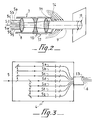
- the device for implementing the method according to the invention in accordance with FIGS. 1, 2 and 3, is thus well suited to manual, reliable and efficient use, in that it comprises, on the one hand, a mechanical assembly 1 containing the laser 2 and its power supply 3, on the other hand, a housing 4, placed on the path of the laser beam 5 coming from said mechanical assembly 1, and containing an optical system intended to separate the laser beam 5 into several other beams laser 5a, 5b, 5c, 5d, 5e, 5f and 5g of approximately equal energies between them, said laser beams 5a, 5b, 5c, 5d, 5e, 5f and 5g being then guided, by a set 6 of optical fibers, towards a handpiece 7 comprising an optical means 8 for recombining the laser beams 5a, 5b, 5c, 5d, 5e, 5f and 5g into a single laser beam 9, and an optical means 10 for adjusting the diameter 11 of said laser beam 9 recombined, this second means 10 being for example constituted by an afocal
- An important characteristic of the device implementing the method according to the invention relates to the choice of optical fibers 6 which transmit the laser beams 5a, 5b, 5c, 5d, 5e, 5f and 5g to the handpiece 7.
- This choice is intimately linked to the choice of the duration of the laser pulses transmitted by these optical fibers 6; in fact, there is a maximum transmission threshold in "peak power" of a laser beam for each type of fiber.
- This explains the role of the optical system 6 for separating the laser beam 5 into several other beams 5a, 5b, 5c, 5d, 5e, 5f and 5g.
- the optical fibers used to guide the laser beams 5a, 5b, 5c, 5d, 5e, 5f and 5g towards the handpiece 7 have a silica core and a silica or hard silicone sheath. This choice seems to be the only possible one under the current conditions of availability of optical fibers, at least as regards the transport of beams having a high peak power.
- optical protection of the optical fibers is provided by means of a reinforced external sheath 13, which makes it possible to use the device on a site.
- the optical face 71 leaving the handpiece 7 is subjected to the aggressions of the dust originating from the spraying of the surface layer of dirt on the stone. Provision is made for a continuous or discontinuous dusting of this optical face 71 by arranging, inside or outside of the handpiece 7, a device providing a jet 14 of a fluid, such as advantageously air. .
- a compressor feeds this device, the connection between the compressor and the device providing the jet 14 can advantageously be a tube protected by the sheath 13 of fiber reinforcement 6.
- the box 4 containing the optical system for separating the laser beam 5 into several beams 5a, 5b, 5c, 5d, 5e, 5f, 5g is preferably a sealed box in which the vacuum is produced: this configuration allows effective protection the optical elements of the dust separation system. In addition, it makes it possible to avoid breakdowns resulting from the focusing of the laser beam 5 on dust, located inside the housing 4, on the path of said laser beam 5.
- optical adjustment means 10 of the diameter 11 of the recombined laser beam 9, which is located in the body of the handpiece 7.
- a dye laser or a laser with a solid amplifying medium of the sapphire type doped with titanium or of the alexandrite type is used.
- Such lasers are lasers with variable or tunable frequency.
- a dye laser thus emits in the visible spectrum, between 500 and 720 nanometers depending on the dye used.
- Titanium-doped spahir lasers on the other hand, emit over a wavelength range from 700 to 1100 nanometers; associated with a frequency doubler, of a well-known type for example using the phenomenon of optical birefringence induced in a material by an electric field, it is then possible to have a variable wavelength range from 350 to 550 nanometers.
- a dye laser can be used in relaxed mode, this then emitting pulses of a few microseconds, or in triggered mode, the pulses then lasting a few nanoseconds.
- the pulse durations vary from 1 to 3 microseconds in relaxed mode, and are a few tens of nanoseconds in triggered mode (comparable duration moreover the duration of a pulse emitted by a non-tunable laser with a solid amplifying medium of the YAG type operating in the same mode).
- a laser with variable or tunable frequency is particularly advantageous in the case where the absorption spectra of the underlying material to be cleaned and of the polluting material covering its surface overlap; there is indeed, in this situation, a risk of alteration of the underlying material, which poses problems which are difficult to solve, except to foresee, in accordance with the teachings of the French patent application FR-2 525 386 already mentioned, operating conditions of the laser capable of providing pulses producing a thermal effect limited by their depth of penetration, during their interaction with the surface to be etched or descaled.
- a tunable laser it is always possible to find a range of working wavelengths outside the absorption spectrum of the underlying material, a wavelength of this range serving, either from the start of treatment if it is correctly absorbed by the polluting material, either gradually, or completely, as the polluted surface layer is volatilized; in this latter configuration, an adequate control device, with or without feedback, allows this evolution of the laser beam in wavelength.
- a particular implementation of this use of a tunable laser to carry out the process according to the present invention consists in cleaning products tubular in an industrial environment, either during their manufacture, or in order to decarbonize them after use.
- the use, in these specific cases, of a tunable laser is not limiting, and it has been shown that a YAG laser operating in triggered mode under the conditions already mentioned above was also suitable.
- the use of excimer lasers which emit ultraviolet radiation has proved to be advantageous, in particular because of the generally vitreous structure of the polluting material to be removed from the surface of the tubular products, in accordance with the description which follows.
- the lubricating layer and the layer of residual oxides present after the forging of a tubular product, for example from a die are eliminated by means of a laser beam scanning at least one of its internal or external surfaces, the laser used for this purpose having all the characteristics necessary for obtaining, on the surface of the underlying solid material, for example, although not exclusively of steel, a shock wave taking off said layers, said laser being moreover of the tunable type, or not, as to its emission frequency.
- the use of a tunable laser can considerably simplify the implementation of the cleaning process; given, in fact, that it is then possible to achieve a better match between the wavelength of the laser used and the respective absorption spectra of the underlying material to be cleaned, and of the polluting material covering its surface, can operate the laser at lower energy, which facilitates its transport by optical fibers, or even makes it possible to use only one, or even to use a type of fiber other than a fiber with silica sheath, or made of hard silicone.
- the field of the invention is particularly that of the restoration of works of art, whether historic monuments, wooden furniture, or glasses or pottery, and also that of cleaning tubes during of their manufacture, or of their subsequent descaling.
Abstract
Description
L'invention concerne un procédé de nettoyage de la surface de matériaux, tels que particulièrement de la pierre, du verre, de l'acier, de la céramique, du bois, du papier ou du carton, à l'exception des matières plastiques et un dispositif de mise en oeuvre de ce procédé, utilisant un laser impulsionnel à impulsions courtes, dont on focalise le faisceau sur la surface à nettoyer.The invention relates to a method for cleaning the surface of materials, such as particularly stone, glass, steel, ceramics, wood, paper or cardboard, with the exception of plastics and a device for implementing this method, using a pulsed laser with short pulses, the beam of which is focused on the surface to be cleaned.
On connait à ce jour plusieurs procédés de nettoyage de la surface d'objets ou d'édifices ayant été pollués, soit en raison de leur usage dans un environnement salissant ou agressif, soit au cours de leur fabrication dans un contexte industriel.To date, several methods of cleaning the surface of objects or buildings that have been polluted are known, either due to their use in a dirty or aggressive environment, or during their manufacture in an industrial context.
Pour ce qui concerne le premier cas, qui recouvre de manière non exhaustive le rajeunissement de l'état de surface des monuments, des objets d'art du type des verres, des céramiques, ou encore de pièces métalliques du type de monnaies, de bronze, d'armes et autres antiquités, il est connu d'utiliser des moyens mécaniques - tels que notamment la projection de silice pulvérulente pour le nettoyage de pierre, ou l'utilisation de fraises de précision pour la désincrustation de concrétions sur de petits objets - ou des moyens chimiques, tels que par exemple des acides. Or, ces techniques nécessitent une mise en oeuvre délicate et longue peu adaptée à un rendement économique convenable, sans pour autant garantir un nettoyage parfait de toute la saleté déposée. Un procédé plus récent, développé en laboratoire, utilise un laser de puissance impulsionnel YAG, fonctionnant en mode relaxé, les impulsions obtenues variant ainsi de 0,1 millisecondes à environ 10 millisecondes.Regarding the first case, which covers in a non-exhaustive way the rejuvenation of the surface condition of monuments, works of art such as glasses, ceramics, or metallic pieces of the type of coins, bronze , weapons and other antiques, it is known to use mechanical means - such as in particular the projection of powdered silica for the cleaning of stone, or the use of precision cutters for the incrustation of concretions on small objects - or chemical means, such as for example acids. However, these techniques require a delicate and long implementation little adapted to a suitable economic yield, without guaranteeing a perfect cleaning of all the deposited dirt. A more recent process, developed in the laboratory, uses a YAG pulse power laser, operating in relaxed mode, the pulses obtained thus varying from 0.1 milliseconds to approximately 10 milliseconds.
Un tel procédé est une illustration du procédé décrit dans le brevet US-4 756 765 qui concerne l'enlèvement de la surface d'un substrat de matériaux polluants présentant une faible conduction thermique, tels des peintures, de la graisse ou des céramiques ; cet enlévement résulte d'un effet thermique, et nécessite, pour ce faire, que le faisceau laser dirigé sur la surface à décaper présente une forte énergie, et une durée d'impulsion typiquement supérieure à 3 microsecondes, de manière à ce que, après focalisation, la densité d'énergie (ou fluence) soit comprise entre 2 J/cm² et 100 J/cm². Ce dernier procédé, même s'il s'inscrit davantage dans un objectif industriel que dans le simple nettoyage d'objets ou d'édifices pollués, met en oeuvre les mêmes phénomènes physiques. On retrouve ainsi des conditions sensiblement identiques de fonctionnement d'un laser dans la demande internationale WO-83/01400, qui décrit un procédé plus particulièrement destiné au nettoyage de la coque de navires ; la fluence atteint une valeur proche de 20 J/cm², le laser utilisé pouvant typiquement être un laser CO₂ ou un laser YAG. A plus basse énergie, il a été proposé de supprimer la couche superficielle de rouille présente sur les surfaces métalliques, ce procédé faisant l'objet de la demande de brevet française FR-2 467 656 ; le laser utilisé est un laser CO₂, focalisé sur la surface à nettoyer de manière à ce que la fluence atteigne environ 5 J/cm². Par ce procédé, on transforme la rouille en magnétite ; mais cette couche étant très adhérente à la superficie du métal traité, elle doit ensuite être retirée par des moyens conventionnels, mécaniques ou chimiques. On retrouve le même inconvénient dans la demande de brevet française FR-2 300 632 ; le laser ne sert ici qu'à échauffer brusquement et intensément la pellicule superficielle d'oxydes présente à la surface d'objets métalliques, celle-ci étant finalement détachée du substrat métallique par une action mécanique, chimique, ou électrochimique.Such a method is an illustration of the method described in US Pat. No. 4,756,765 which relates to the removal from the surface of a substrate of polluting materials having low thermal conduction, such as paints, grease or ceramics; this removal results from an effect thermal, and requires, for this, that the laser beam directed on the surface to be etched has a high energy, and a pulse duration typically greater than 3 microseconds, so that, after focusing, the energy density (or fluence) is between 2 J / cm² and 100 J / cm². The latter process, even if it falls more within an industrial objective than in the simple cleaning of polluted objects or buildings, uses the same physical phenomena. There are thus substantially identical operating conditions of a laser in international application WO-83/01400, which describes a process more particularly intended for cleaning the hull of ships; the fluence reaches a value close to 20 J / cm², the laser used can typically be a CO₂ laser or a YAG laser. At lower energy, it has been proposed to remove the surface layer of rust present on metal surfaces, this process being the subject of French patent application FR-2 467 656; the laser used is a CO₂ laser, focused on the surface to be cleaned so that the fluence reaches approximately 5 J / cm². By this process, rust is transformed into magnetite; but since this layer is very adherent to the surface of the treated metal, it must then be removed by conventional, mechanical or chemical means. We find the same drawback in French patent application FR-2 300 632; the laser is used here only to suddenly and intensely heat the surface oxide film present on the surface of metallic objects, this latter being finally detached from the metallic substrate by a mechanical, chemical, or electrochemical action.
On connait encore le brevet européen EP-A-233.755 qui préconise l'emploi d'une source laser pour la préparation de surfaces d'objets en plastique moulé. De tels objets présentent en effet sur leur surface externe après démoulage un film d'un agent de démoulage empèchant lesdits objets d'adhérer aux parois du moule lors de l'opération de démoulage. Un tel film doit être impérativement retiré car il rend quasiment impossible toute opération ultérieure de peinture ou de collage sur les objets en plastique. Le précédé décrit dans ce brevet a pour but principal d'enlever de la surface des objets en plastique moulé, un film contenant à la fois l'agent de démoulage et de la matière plastique constitutive de l'objet à préparer ; il s'agit d'une source utilisant un faisceau laser émettant dans l'ultra-violet du type à Excimères ou YAG quadruplé. S'il est certain qu'une telle source met en oeuvre des densités d'énergie bien inférieures à ce que l'on utilise généralement dans le nettoyage de matériau (inférieur à un joule/cm2) on sait bien que l'énergie des photons est dans ce cas suffisante pour casser les liaisons chimiques des matériaux de surface et les modifier. Appliquées à des matières organiques telles que par exemple de simples plastiques, on sait bien qu'un tel faisceau procure, pour l'essentiel, un effet photochimique aboutissant à un enlèvement de la matière plastique mélée à la couche d'agent de démoulage par simple évaporation ou décomposition.European patent EP-A-233,755 is also known, which recommends the use of a laser source for the preparation of surfaces of molded plastic objects. Such objects have in fact on their external surface after demolding a film of a release agent preventing said objects from adhering to the walls of the mold during the demolding operation. Such a film must be removed because it makes it almost impossible any subsequent painting or bonding operation on plastic objects. The precedent described in this patent has the main purpose of removing from the surface of molded plastic objects, a film containing both the release agent and the plastic material constituting the object to be prepared; it is a source using a laser beam emitting in the ultraviolet type of the Excimer or YAG type quadrupled. If it is certain that such a source implements energy densities much lower than what is generally used in the cleaning of material (less than a joule / cm2) it is well known that the energy of photons is in this case sufficient to break the chemical bonds of surface materials and modify them. Applied to organic materials such as, for example, simple plastics, it is well known that such a beam provides, essentially, a photochemical effect resulting in removal of the plastic material mixed with the release agent layer by simple evaporation or decomposition.
Tous ces procédés présentent, par conséquent, des inconvénients liés à leur spécificité et ils ne constituent en aucun cas un moyen général et unique de nettoyage de matériaux, objets ou édifices, se situant dans un environnement polluant ou industriel. Par ailleurs, ces procédés restent des moyens agressifs dont il s'avère difficile de limiter l'action à la seule couche de saleté incrustée. Notamment, du fait que les spectres d'absorption des matériaux polluants ou sous-jacents qui sont traités peuvent être très larges ou, au contraire, très étroits, il peut se produire, dans bien des cas, une inadéquation de la longueur d'onde du faisceau laser utilisé par rapport au nettoyage recherché ; ce faisceau peut ainsi être absorbé non seulement par la couche superficielle polluante à éliminer, mais également par le matériau sous-jacent, d'où un risque d'endommagement de celui-ci par échauffement. En effet, la puissance moyenne déposée par le faisceau laser sur le matériau à nettoyer atteint des valeurs élevées lorsque, d'une part les impulsions laser sont longues, et d'autre part l'énergie des impulsions et leur fréquence sont trop élevées, ce qui est le cas dans les procédés de l'art antérieur. On peut enfin citer, dans un domaine d'application très spécifique, la demande de brevet française FR-2 525 380 ; dans ce document, il est établi qu'on peut décomtaminer des composants de centrales nucléaires présentant une couche d'oxydes radioactifs au moyen d'un laser impulsionnel d'intensité suffisante pour permettre une pénétration thermique correspondant à l'épaisseur de la couche d'oxydes, sans endommager le substrat métallique sous-jacent. Ce dernier procédé est sensiblement différent des procédés précédemment décrits, en ce sens que s'il préconise l'utilisation de densités d'énergie supérieures à 4 J/cm², normalement proches de 10 J/cm², les impulsions laser utilisées peuvent aussi être plus courtes. Ce procédé présente néanmoins l'inconvénient de mettre en oeuvre un effet thermique dont on a précédemment mentionné les risques vis à vis du matériau sous-jacent.All these processes therefore have drawbacks linked to their specificity and they do not in any way constitute a general and unique means of cleaning materials, objects or buildings, located in a polluting or industrial environment. Furthermore, these methods remain aggressive means, the action of which proves difficult to limit to the only layer of encrusted dirt. In particular, because the absorption spectra polluting or underlying materials which are treated can be very wide or, on the contrary, very narrow, it can occur, in many cases, an inadequacy of the wavelength of the laser beam used in relation to the cleaning sought; this beam can thus be absorbed not only by the polluting surface layer to be eliminated, but also by the underlying material, hence a risk of damage to the latter by heating. Indeed, the average power deposited by the laser beam on the material to be cleaned reaches high values when, on the one hand the laser pulses are long, and on the other hand the energy of the pulses and their frequency are too high, this which is the case in the processes of the prior art. Finally, we can cite, in a very specific field of application, French patent application FR-2 525 380; in this document, it is established that components of nuclear power plants having a layer of radioactive oxides can be decomtaminated by means of a pulse laser of sufficient intensity to allow thermal penetration corresponding to the thickness of the layer of oxides, without damaging the underlying metal substrate. The latter method is significantly different from the previously described methods, in that if it recommends the use of energy densities greater than 4 J / cm², normally close to 10 J / cm², the laser pulses used can also be more short. This method nevertheless has the drawback of implementing a thermal effect of which the risks with respect to the underlying material have previously been mentioned.
La présente invention vise à remédier à ces inconvénients, et propose une alternative à ces procédés de nettoyage utilisant l'effet de volatilisation des couches superficielles du matériau lorsque celui-ci est soumis à un rayonnement optique cohérent dont la densité, en puissance instantanée, est suffisante pour générer, à l'interface de la matière et du milieu extérieur, une onde de choc ayant pour effet de décoller au moins une partie de la couche superficielle polluante recouvrant ledit matériau.The present invention aims to remedy these drawbacks, and proposes an alternative to these cleaning methods using the effect of volatilization of the surface layers of the material when the latter is subjected to coherent optical radiation whose density, in instantaneous power, is sufficient to generate, at the interface of the material and the external medium, a shock wave having the effect of peeling off at least part of the polluting surface layer covering said material.
Il convient donc ici de raisonner plus en terme de densité de puissance qu'en terme de densité d'énergie, ou fluence, du faisceau laser ; en effet, l'onde de choc visée par la présente invention est due à une interaction instantanée d'un faisceau de forte puissance avec la surface à nettoyer, c'est-à-dire qu'il s'agit d'une interaction brève avant d'être énergétique. C'est pourquoi, par exemple, une impulsion laser présentant un pic élevé suivi d'une décroissance plus lente convient tout à fait à la mise en oeuvre de l'invention, même si, par ailleurs, l'énergie déposée, que l'on calcule de la manière habituelle par intégration au cours du temps de la puissance instantanée, retrouve des valeurs comparables à celles décrites dans les brevets antérieurs déjà mentionnés. En l'espèce, l'onde de choc ne peut s'établir qu'en dehors de tout phénomène thermique d'absorption majoritaire, et il est clair qu'on doit alors éviter des impulsions laser longues et/ou trop énergétiques.It is therefore appropriate here to reason more in terms of power density than in terms of energy density, or fluence, of the laser beam; in fact, the shock wave targeted by the present invention is due to an instantaneous interaction of a high-power beam with the surface to be cleaned, that is to say that it is a brief interaction before being energetic. This is why, for example, a laser pulse having a high peak followed by a slower decay is entirely suitable for the implementation of the invention, even if, moreover, the energy deposited, that the the instantaneous power is calculated in the usual way by integrating over time, values comparable to those described in the previous patents already mentioned are found. In this case, the shock wave can only be established outside any thermal phenomenon of majority absorption, and it is clear that one must then avoid long laser pulses and / or too energetic.
A cet égard, le procédé selon l'invention pour le nettoyage de la surface de tout matériau autre que le plastique, focalisant un faisceau laser impulsionnel de forte puissance instantannée sur ladite surface est caractérisé en ce que le laser utilisé à cet effet fournit des impulsions dont la longueur d'onde est comprise entre 500 et 1100 nanomètres, dont la durée est comprises entre quelques nanosecondes et quelques microsecondes, dont la puissance instantanée a une valeur comprise entre quelques centaines de kilowatts et quelques dizaines de mégawatts et qui est focalisé sur la surface à nettoyer de manière à ce que la densité de puissance par impulsion soit comprise entre quelques centaines de kilowatts par cm² et quelques dizaines de mégawatts par cm², de manière à générer, à l'interface du matériau, une onde de choc non thermique ayant pour effet de décoller au moins une partie de la couche superficielle polluante recouvrant ledit matériau.In this regard, the method according to the invention for cleaning the surface of any material other than plastic, focusing a pulsed laser beam of high instantaneous power on said surface is characterized in that the laser used for this purpose provides pulses whose wavelength is between 500 and 1100 nanometers, whose duration is between a few nanoseconds and a few microseconds, whose instantaneous power has a value between a few hundred kilowatts and a few tens of megawatts and which is focused on the surface to be cleaned so that the power density per pulse is between a few hundred kilowatts per cm² and a few tens of megawatts per cm², so as to generate, at the interface of the material, a non-thermal shock wave having the effect of peeling off at least part of the polluting surface layer covering said material.
Suivant une caractéristique complémentaire de l'invention, le laser fournit des impulsions dont la durée peut varier entre quelques nanosecondes et 3 microsecondes. Suivant une autre caractéristique, la longueur d'onde de la radiation émise par ce laser se situe à l'intérieur du spectre d'absorption du matériau polluant, formant une couche superficielle sur la surface du matériau à nettoyer.According to a complementary characteristic of the invention, the laser provides pulses whose duration can vary between a few nanoseconds and 3 microseconds. According to another characteristic, the wavelength of the radiation emitted by this laser is located inside the absorption spectrum of the polluting material, forming a surface layer on the surface of the material to be cleaned.
Par ailleurs, comme le spectre d'absorption du matériau polluant est généralement différent du spectre d'absorption du matériau à nettoyer sous-jacent, au fur et à mesure que le nettoyage de la surface du matériau s'effectue, il apparait des couches superficielles moins polluées et donc généralement plus réfléchissantes vis à vis du rayonnement laser : les risques d'altération du matériau sous-jacent sont ainsi pratiquement inexistants. Cet effet se comprend particulièrement bien dans le cas où le matériau à nettoyer est de la pierre, du type du granit par exemple.Furthermore, since the absorption spectrum of the polluting material is generally different from the absorption spectrum of the underlying material to be cleaned, as the cleaning of the material surface takes place, surface layers appear less polluted and therefore generally more reflective with respect to laser radiation: the risks of alteration of the underlying material are thus practically non-existent. This effect is particularly well understood in the case where the material to be cleaned is stone, for example of the granite type.
Le cas du décapage ou du décalaminage de matériaux notamment métalliques, et plus généralement de matériaux dont le spectre d'absorption recouvre en partie celui du matériau polluant, est identique, mais peut nécessiter, conformément à une caractéristique complémentaire de l'invention, l'utilisation d'un laser à fréquence d'émission variable ou accordable, dont la longueur d'onde d'émission peut être réglée continument ou discrètement au fur et à mesure du nettoyage, la plage de longueur d'onde nécessaire à cet effet étant fonction des deux spectres d'absorption. L'utilisation d'un tel laser rend également plus efficace le procédé conforme à l'invention lorsque le spectre d'absorption du matériau polluant est très étroit, le laser accordable permettant alors de volatiliser ce matériau dans les meilleures conditions. A l'inverse, on peut profiter d'une "fenêtre" de transparence du matériau sous-jacent à nettoyer vis à vis de certaines longueurs d'onde pouvant être émises par le laser accordable utilisé, ces longueurs d'onde étant par ailleurs absorbées par le matériau polluant ; dans ces conditions, le risque d'endommagement du matériau sous-jacent est nettement diminué.The case of pickling or descaling of particularly metallic materials, and more generally of materials whose absorption spectrum partly covers that of the polluting material, is identical, but may require, in accordance with a complementary characteristic of the invention, the use of a laser with variable or tunable emission frequency, the emission wavelength of which can be adjusted continuously or discreetly during cleaning, the wavelength range necessary for this purpose being dependent of the two absorption spectra. The use of such a laser also makes the method according to the invention more effective when the absorption spectrum of the polluting material is very narrow, the tunable laser then making it possible to volatilize this material under the best conditions. Conversely, one can benefit from a "window" of transparency of the underlying material to be cleaned with respect to certain wavelengths that can be emitted by the tunable laser used, these wavelengths being moreover absorbed by the polluting material; under these conditions, the risk of damage to the underlying material is significantly reduced.
L'utilisation d'impulsions laser de forte puissance instantanée constitue donc l'apport principal du procédé selon l'invention ; l'énergie de chaque impulsion étant ainsi fixée, on sait alors parfaitement que plus on diminue la durée desdites impulsions, plus on augmente leur "puissance crête". En focalisant cette puissance disponible sur la surface à nettoyer selon un diamètre de faisceau suffisamment faible, la densité de puissance disponible est de plus en plus importante.The use of laser pulses of high instantaneous power therefore constitutes the main contribution of the method according to the invention; the energy of each pulse being thus fixed, we then know perfectly well that the more we decrease the duration of said pulses, the more we increase their "power peak ". By focusing this available power on the surface to be cleaned according to a sufficiently small beam diameter, the density of available power is more and more important.
La faible durée des impulsions permet de déposer sur le matériau à nettoyer une puissance moyenne seulement égale à quelques watts ou quelques dizaines de watts ; cette puissance est réglable si on dispose, par ailleurs, d'un moyen de contrôle de la fréquence de répétition des impulsions émises par le laser.The short duration of the pulses makes it possible to deposit on the material to be cleaned an average power only equal to a few watts or a few tens of watts; this power is adjustable if there is, moreover, a means of controlling the repetition frequency of the pulses emitted by the laser.
Cette faible puissance moyenne requise par le procédé conforme à la présente invention permet, en outre, de disposer d'un laser de faible encombrement et consommant peu d'énergie, même lorsque le rendement de fonctionnement de ce laser est faible. Ainsi pourra-t-on utiliser, de manière bien entendu non exhaustive, des lasers à milieu amplificateur solide, et notamment des lasers du type YAG dopé au néodyme, du type à saphir dopé au titane, et du type à alexandrite, des lasers à colorant, ou encore des lasers à excimères.This low average power required by the method according to the present invention also makes it possible to have a laser of small bulk and consuming little energy, even when the operating efficiency of this laser is low. It will thus be possible, of course, to use in a non-exhaustive manner, lasers with a solid amplifying medium, and in particular lasers of the YAG type doped with neodymium, of the sapphire type doped with titanium, and of the alexandrite type, lasers with dye, or excimer lasers.
D'autres caractéristiques et avantages du procédé selon l'invention ressortiront mieux de la description qui va suivre d'un mode de mise en oeuvre non limitatif de ce procédé en référence au dessins annexés sur lesquels :
- la figure 1 est une vue générale d'un dispositif de mise en oeuvre du procédé selon l'invention, applicable par exemple au nettoyage des monuments historiques.
- la figure 2 est une vue en élévation de la pièce à main telle que décrite par la suite.
- la figure 3 est un schéma optique de principe du système optique de séparation du faisceau laser tel que décrit par la suite.
- Figure 1 is a general view of a device for implementing the method according to the invention, applicable for example to the cleaning of historic monuments.
- Figure 2 is an elevational view of the handpiece as described below.
- FIG. 3 is a basic optical diagram of the optical system for separating the laser beam as described below.
Conformément à une première forme de réalisation du procédé selon l'invention, il est utilisé un laser à milieu amplificateur solide du type cristal ou verre de grenat d'yttrium et d'aluminium YAG dopé au néodyme, fonctionnant en mode déclenché, et fournissant par conséquent des impulsions dont la durée peut varier entre un dizaine de nanosecondes et une trentaine de nanosecondes ; afin de se trouver dans les conditions de fonctionnement spécifiques au procédé de l'invention, l'énergie par impulsion est égale au maximum à environ 500 millijoules, et le diamètre moyen du faisceau issu dudit laser présente un diamètre inférieur à une dizaine de millimètres sur la surface à nettoyer.In accordance with a first embodiment of the method according to the invention, a laser is used with solid amplifying medium of the crystal or glass type of yttrium garnet and YAG aluminum doped with neodymium, operating in triggered mode, and providing by consequently pulses whose duration can vary between ten nanoseconds and thirty nanoseconds; in order to be within operating conditions specific to the process of the invention, the energy per pulse is at most equal to around 500 millijoules, and the average diameter of the beam coming from said laser has a diameter of less than ten millimeters on the surface to be cleaned.
Un tel laser a un encombrement réduit, de l'ordre du m³, ce qui est un avantage pour son transport, et son alimentation en énergie est constituée classiquement d'une armoire d'encombrement équivalent. La consommation s'établit à environ 4 kilowatts par heure dans les conditions précitées, et en choisissant une fréquence de répétition des impulsions égales à une trentaine de hertz. Ceci permet de relier le dispositif à un groupe électrogène transportable, notamment utilisable sur un chantier lors du nettoyage d'objets ou d'édifices se situant en milieu pollué, tels des statues, des monuments historiques, ou autres antiquités. Le nettoyage d'autres édifices plus courants est tout à fait envisageable, mais son intérêt économique reste à démontrer.Such a laser has a reduced size, of the order of m³, which is an advantage for its transport, and its power supply conventionally consists of an equivalent size cabinet. The consumption is established at approximately 4 kilowatts per hour under the aforementioned conditions, and by choosing a frequency of repetition of the pulses equal to about thirty hertz. This makes it possible to connect the device to a transportable generator, in particular usable on a site during the cleaning of objects or buildings located in a polluted environment, such as statues, historical monuments, or other antiques. The cleaning of other more common buildings is entirely possible, but its economic interest remains to be demonstrated.
Le choix de la fréquence de fonctionnement du laser n'est pas très important mais il semble, d'après les études réalisées en laboratoire et sur le chantier, qu'une fréquence égale à quelques dizaines de hertz permette d'obtenir les meilleurs résultats : en effet, il semble que cette plage de fréquence convienne d'une façon satisfaisante à une mise en oeuvre particulière du procédé selon l'invention dont la description suivante fournit un exemple non limitatif pour ce qui concerne le nettoyage d'un édifice en milieu extérieur.The choice of the frequency of operation of the laser is not very important but it seems, according to studies carried out in laboratory and on site, that a frequency equal to a few tens of hertz allows to obtain the best results: in fact, it seems that this frequency range is satisfactorily suitable for a particular implementation of the method according to the invention, the following description of which provides a non-limiting example as regards the cleaning of a building in an outdoor environment .
Ainsi, conformément à la figure 1, on choisit de confier à un opérateur le déplacement du lieu de focalisation du faisceau laser sur la surface à nettoyer, préférentiellement à un déplacement automatisé, du type balayage optique, qui aurait le désavantage de provoquer une série de défauts répétitifs, conséquences d'une hétérogénéité spatiale en énergie de la section du faisceau laser, même après sa focalisation sur la surface à nettoyer. On notera cependant qu'un déplacement automatisé est utile dans d'autres applications du procédé de l'invention, notamment dans un contexte industriel.Thus, in accordance with FIG. 1, it is chosen to entrust an operator with the displacement of the focal point of the laser beam on the surface to be cleaned, preferably with an automated displacement, of the optical scanning type, which would have the disadvantage of causing a series of repetitive defects, consequences of a spatial heterogeneity in energy of the section of the laser beam, even after focusing on the surface to be cleaned. Note, however, that an automated movement is useful in other applications of the process of the invention, in particular in an industrial context.
Le dispositif de mise en oeuvre du procédé selon l'invention, conformément aux figures 1, 2 et 3, est ainsi bien adapté à une utilisation manuelle, fiable et efficace, en ce qu'il comprend, d'une part, un ensemble mécanique 1 contenant le laser 2 et son alimentation électrique 3, d'autre part, un boîtier 4, placé sur le trajet du faisceau laser 5 issu dudit ensemble mécanique 1, et contenant un système optique destiné à séparer le faisceau laser 5 en plusieurs autres faisceaux laser 5a,5b,5c,5d,5e,5f et 5g d'énergies approximativement égales entre elles, lesdits faisceaux laser 5a,5b,5c,5d,5e,5f et 5g étant alors guidés, par un ensemble 6 de fibres optiques, vers une pièce à main 7 comprenant un moyen optique 8 de recombinaison des faisceaux laser 5a,5b,5c,5d,5e,5f et 5g en un faisceau laser unique 9, et un moyen optique 10 de réglage du diamètre 11 dudit faisceau laser 9 recombiné, ce deuxième moyen 10 étant par exemple constitué par un montage optique afocal 12, ladite pièce à main 7 ayant une taille adéquate pour être facilement manipulée par l'opérateur procédant au nettoyage de la surface à nettoyer.The device for implementing the method according to the invention, in accordance with FIGS. 1, 2 and 3, is thus well suited to manual, reliable and efficient use, in that it comprises, on the one hand, a mechanical assembly 1 containing the
L'efficacité de ce nettoyage est ainsi très élevée: dans des conditions courantes de nettoyage de monuments historiques en pierre, on a estimé pouvoir restaurer complètement une surface égale à un mètre carré en une heure, ce rendement étant à comparer au rendement actuel des procédés mécaniques de projection de silice pulvérulente égal, au maximum, à un mètre carré par jour.The efficiency of this cleaning is therefore very high: under current conditions for cleaning historic stone monuments, it has been estimated that a surface equal to one square meter can be completely restored in one hour, this yield being compared to the current yield of the processes mechanical projection of powdered silica, equal to a maximum of one square meter per day.
Une caractéristique importante du dispositif mettant en oeuvre le procédé selon l'invention concerne le choix des fibres optiques 6 qui transmettent les faisceaux laser 5a,5b,5c,5d,5e,5f et 5g à la pièce à main 7. Ce choix est intimement lié au choix de la durée des impulsions laser transmises par ces fibres optiques 6 ; en effet, il existe un seuil maximum de transmission en "puissance crête" d'un faisceau laser pour chaque type de fibre. Ceci explique le rôle du système optique 6 de séparation du faisceau laser 5 en plusieurs autres faisceaux 5a,5b,5c,5d,5e,5f et 5g.An important characteristic of the device implementing the method according to the invention relates to the choice of
Préférentiellement, les fibres optiques utilisées pour guider les faisceaux laser 5a,5b,5c,5d,5e,5f et 5g vers la pièce à main 7 possèdent un coeur en silice et une gaine en silice ou en silicone dure. Ce choix semble être le seul possible dans les conditions actuelles de disponibilité des fibres optiques, du moins pour ce qui concerne le transport de faisceaux présentant une forte puissance crête.Preferably, the optical fibers used to guide the
On notera également qu'on choisit une longueur d'environ 30 mètres de fibres optiques, ce qui permet à l'opérateur de travailler à une distance suffisante des éléments fixes du dispositif mettant en oeuvre le procédé selon l'invention.It will also be noted that a length of approximately 30 meters of optical fibers is chosen, which allows the operator to work at a sufficient distance from the fixed elements of the device implementing the method according to the invention.
Il est enfin prévu une protection mécanique des fibres optiques au moyen d'une gaine externe 13 renforcée, ce qui permet d'utiliser le dispositif sur un chantier.Finally, mechanical protection of the optical fibers is provided by means of a reinforced
Par ailleurs, il est nécessaire de protéger le dispositif dans son intégralité contre la poussière résultant du nettoyage effectué par le laser : ainsi, à proximité de la surface à nettoyer, soit à environ une vingtaine de centimètres, la face optique 71 de sortie de la pièce à main 7 subit les agressions de la poussière provenant qui résulte de la pulvérisation de la couche superficielle de saleté se trouvant sur la pierre. On prévoit un dépoussiérage continu ou discontinu de cette face optique 71 en disposant, à l'intérieur ou à l'extérieur de la pièce à main 7, un dispositif procurant un jet 14 d'un fluide, tel qu'avantageusement de l'air. Un compresseur alimente ce dispositif, la liaison entre le compresseur et le dispositif procurant le jet 14 pouvant avantageusement être un tube protégé par la gaine 13 de renforcement des fibres 6.Furthermore, it is necessary to protect the entire device against dust resulting from the cleaning carried out by the laser: thus, near the surface to be cleaned, that is to say about twenty centimeters, the
En outre, le boitier 4 contenant le système optique de séparation du faisceau laser 5 en plusieurs faisceaux 5a, 5b, 5c, 5d, 5e, 5f, 5g est préférentiellement un boitier étanche dans lequel on réalise le vide : cette configuration permet de protéger efficacement les éléments optiques du système de séparation du faisceau contre la poussière. De plus, il permet d'éviter les claquages résultant de la focalisation du faisceau laser 5 sur des poussières, se trouvant à l'intérieur du boîtier 4, sur la trajet dudit faisceau laser 5.In addition, the
On notera enfin le rôle du moyen optique de réglage 10, du diamètre 11 du faisceau laser 9 recombiné, qui se trouve dans le corps de la pièce à main 7. Ce moyen optique 10, constitué par exemple par un montage optique afocal 12, comprenant une lentille divergente et une lentille convergente, permet, à partir d'une même énergie du faisceau laser 9 disponible, d'obtenir une densité de "puissance crête" variable : l'opérateur a ainsi la possibilité de varier l'efficacité du nettoyage en fonction du niveau d'incrustation de saleté qu'il constate sur la surface à nettoyer : en augmentant le diamètre 11 par le biais du moyen optique 10, il fait directement varier cette efficacité du nettoyage.Finally, note the role of the optical adjustment means 10, of the
Conformément à une deuxième forme de réalisation du procédé selon l'invention, il est utilisé un laser à colorant ou un laser à milieu amplificateur solide du type saphir dopé au titane ou du type alexandrite. De tels lasers sont des lasers à fréquence variable ou accordable. Typiquement, un laser à colorant émet ainsi dans le spectre visible, entre 500 et 720 nanomètres suivant le colorant utilisé. Les lasers à spahir dopé au titane émettent, quant à eux, sur une plage de longueur d'onde allant de 700 à 1100 nanomètres ; associé à un doubleur de fréquence, d'un type par exemple bien connu utilisant le phénomène de biréfringence optique induite dans un matériau par un champ électrique, il est alors possible de disposer d'une plage de longueur d'onde variable de 350 à 550 nanomètres. De cette façon, il est donc possible, après étude préalable des spectres d'absorption respectifs du matériau à nettoyer, et du matériau polluant formant une couche à sa superficie, de choisir et de régler la longueur d'onde d'émission du laser accordable utilisé de manière à se trouver dans des conditions optimales de nettoyage, c'est-à-dire associant la meilleure efficacité d'absorption du matériau polluant vis à vis du faisceau laser, sans se départir, néanmoins, d'une durée d'impulsion suffisament courte, apte à générer le phénomène d'onde de choc caractérisant le procédé de l'invention.In accordance with a second embodiment of the method according to the invention, a dye laser or a laser with a solid amplifying medium of the sapphire type doped with titanium or of the alexandrite type is used. Such lasers are lasers with variable or tunable frequency. Typically, a dye laser thus emits in the visible spectrum, between 500 and 720 nanometers depending on the dye used. Titanium-doped spahir lasers, on the other hand, emit over a wavelength range from 700 to 1100 nanometers; associated with a frequency doubler, of a well-known type for example using the phenomenon of optical birefringence induced in a material by an electric field, it is then possible to have a variable wavelength range from 350 to 550 nanometers. In this way, it is therefore possible, after prior study of the respective absorption spectra of the material to be cleaned, and of the polluting material forming a layer on its surface, to choose and adjust the emission wavelength of the tunable laser used so as to be in optimal cleaning conditions, that is to say combining the best absorption efficiency of the polluting material with respect to the laser beam, without however departing from a pulse duration enough short, capable of generating the shock wave phenomenon characterizing the method of the invention.
Ainsi, on peut utiliser un laser à colorant en mode relaxé, celui-ci émettant alors des impulsions de quelques microsecondes, ou en mode déclenché, les impulsions durant alors quelques nanosecondes. Par contre, dans le cas des lasers à milieu amplificateur solide d'un type déjà mentionné, les durées d'impulsions varient de 1 à 3 microsecondes en mode relaxé, et sont de quelques dizaines de nanosecondes en mode déclenché (durée comparable d'ailleurs à la durée d'une impulsion émise par un laser non accordable à milieu amplificateur solide du type YAG fonctionnant suivant le même mode).Thus, a dye laser can be used in relaxed mode, this then emitting pulses of a few microseconds, or in triggered mode, the pulses then lasting a few nanoseconds. On the other hand, in the case of lasers with a solid amplifying medium of a type already mentioned, the pulse durations vary from 1 to 3 microseconds in relaxed mode, and are a few tens of nanoseconds in triggered mode (comparable duration moreover the duration of a pulse emitted by a non-tunable laser with a solid amplifying medium of the YAG type operating in the same mode).
L'utilisation d'un laser à fréquence variable ou accordable est particulièrement intéressante dans le cas où les spectres d'absorption du matériau sous-jacent à nettoyer et du matériau polluant recouvrant sa surface se recoupent ; il existe en effet, dans cette situation, un risque d'altération du matériau sous-jacent, ce qui pose des problèmes difficiles à résoudre, sauf à prévoir, conformément aux enseignements de la demande de brevet française FR-2 525 386 déjà mentionnée, des conditions de fonctionnement du laser susceptibles de fournir des impulsions produisant un effet thermique limité par leur profondeur de pénétration, lors de leur interaction avec la surface à décaper ou à décalaminer. En utilisant un laser accordable, il est toujours possible de trouver une plage de longueurs d'onde de travail échappant au spectre d'absorption du matériau sous-jacent, une longueur d'onde de cette plage servant, soit dès le début du traitement si elle est correctement absorbée par le matériau polluant, soit progressivement, ou complétement, au fur et à mesure que la couche polluée superficielle est volatilisée ; dans cette dernière configuration, un dispositif de contrôle adéquat, avec ou sans contre-réaction, permet cette évolution du faisceau laser en longueur d'onde.The use of a laser with variable or tunable frequency is particularly advantageous in the case where the absorption spectra of the underlying material to be cleaned and of the polluting material covering its surface overlap; there is indeed, in this situation, a risk of alteration of the underlying material, which poses problems which are difficult to solve, except to foresee, in accordance with the teachings of the French patent application FR-2 525 386 already mentioned, operating conditions of the laser capable of providing pulses producing a thermal effect limited by their depth of penetration, during their interaction with the surface to be etched or descaled. Using a tunable laser, it is always possible to find a range of working wavelengths outside the absorption spectrum of the underlying material, a wavelength of this range serving, either from the start of treatment if it is correctly absorbed by the polluting material, either gradually, or completely, as the polluted surface layer is volatilized; in this latter configuration, an adequate control device, with or without feedback, allows this evolution of the laser beam in wavelength.
Une mise en oeuvre particulière de cette utilisation d'un laser accordable pour réaliser le procédé conforme à la présente invention consiste à nettoyer des produits tubulaires dans un environnement industriel, soit lors de leur fabrication, soit dans le but de les décalaminer après usage. L'utilisation, dans ces cas spécifiques, d'un laser accordable n'est pas limitative, et on montré qu'un laser YAG fonctionnant en mode déclenché dans les conditions déjà mentionnées plus haut convenait également. En outre, l'utilisation des lasers à excimères qui émettent un rayonnement ultraviolet s'est avérée intéressante, notamment du fait de la structure généralement vitreuse du matériau polluant à éliminer de la surface des produits tubulaires, conformément à la description qui suivre.A particular implementation of this use of a tunable laser to carry out the process according to the present invention consists in cleaning products tubular in an industrial environment, either during their manufacture, or in order to decarbonize them after use. The use, in these specific cases, of a tunable laser is not limiting, and it has been shown that a YAG laser operating in triggered mode under the conditions already mentioned above was also suitable. In addition, the use of excimer lasers which emit ultraviolet radiation has proved to be advantageous, in particular because of the generally vitreous structure of the polluting material to be removed from the surface of the tubular products, in accordance with the description which follows.
Il s'agit ici de décaper, de dégraisser, ou plus généralement d'enlever les produits lubrifiants, tels du verre fusible ou de la graisse, se trouvant à l'intérieur et/ou à l'extérieur de produits tubulaires issus par exemple d'une filière, ou ayant été percés par un mandrin, puis expansés ou réduits par des moyens conventionnels connus. A leur sortie du dispositif de mise en forme, c'est-à-dire du dispositif de forgeage, les tubes ou produits tubulaires, sont ainsi très sales car leur réalisation met en oeuvre des lubrifiants, issus notamment de gargouzes placées en amont du dispositif de forgeage. Jusqu'à présent, il était connu de débarrasser les produits tubulaires de leur enduit lubrifiant par des moyens chimiques et/ou mécaniques du type d'un grenaillage interne et/ou externe ; une telle opération est nécessaire pour certains traitements ultérieurs spécifiques.This involves stripping, degreasing, or more generally removing lubricants, such as fusible glass or grease, found inside and / or outside of tubular products, for example from 'a die, or having been drilled by a mandrel, then expanded or reduced by known conventional means. On leaving the shaping device, that is to say the forging device, the tubes or tubular products are thus very dirty because their production uses lubricants, in particular from gargouzes placed upstream of the device forging. Until now, it was known to rid the tubular products of their lubricant coating by chemical and / or mechanical means of the type of internal and / or external shot blasting; such an operation is necessary for certain specific subsequent treatments.
Conformément à la présente invention, on élimine la couche lubrifiante et la couche d'oxydes résiduelles présentes après le forgeage d'un produit tubulaire, issu par exemple d'une filière, au moyen d'un faisceau laser balayant au moins l'une de ses surfaces interne ou externe, le laser utilisé à cet effet ayant toutes les caractéristiques nécessaires à l'obtention, sur la surface de la matière solide sous-jacente, par exemple, quoique non exclusivement en acier, d'une onde de choc décollant lesdites couches, ledit laser étant par ailleurs du type accordable, ou non, quant à sa fréquence d'émission.According to the present invention, the lubricating layer and the layer of residual oxides present after the forging of a tubular product, for example from a die, are eliminated by means of a laser beam scanning at least one of its internal or external surfaces, the laser used for this purpose having all the characteristics necessary for obtaining, on the surface of the underlying solid material, for example, although not exclusively of steel, a shock wave taking off said layers, said laser being moreover of the tunable type, or not, as to its emission frequency.
De la même façon, après installation en atmosphère industrielle d'un tube pollué par des dépôts, ou soumis à des conditions d'utilisation agressives, notamment dans des centrales thermiques, il est possible de décalaminer ce tube par le même procédé. La mise en oeuvre de l'invention nécessite en ce cas le transport du faisceau laser jusqu'à proximité de la zone d'interaction choisie, et on conçoit alors bien tout l'avantage procuré par le transport de ce faisceau au moyen d'au moins une fibre optique, suivant en cela les enseignements de la présente invention tels que décrits plus haut dans le texte. A ce titre, il convient de noter que l'utilisation d'un laser accordable peut considérablement simplifier la mise en oeuvre du procédé de nettoyage ; étant donné, en effet, qu'il est alors possible de réaliser une meilleure adéquation entre la longueur d'onde du laser utilisé et les spectres d'absorption respectifs du matériau sous-jacent à nettoyer, et du matériau polluant recouvrant sa surface, on peut faire fonctionner le laser à moindre énergie, ce qui facilite son transport par fibres optiques, voire permet de n'en utiliser qu'une seule, ou encore d'utiliser un type de fibre autre qu'une fibre avec gaine en silice, ou en silicone dur.Similarly, after installation in an industrial atmosphere of a tube polluted by deposits, or subjected to aggressive conditions of use, in particular in thermal power stations, it is possible to descale this tube by the same process. The implementation of the invention requires in this case the transport of the laser beam to close to the chosen interaction area, and it is therefore easy to see all the advantage obtained by the transport of this beam by means of minus an optical fiber, thereby following the teachings of the present invention as described above in the text. As such, it should be noted that the use of a tunable laser can considerably simplify the implementation of the cleaning process; given, in fact, that it is then possible to achieve a better match between the wavelength of the laser used and the respective absorption spectra of the underlying material to be cleaned, and of the polluting material covering its surface, can operate the laser at lower energy, which facilitates its transport by optical fibers, or even makes it possible to use only one, or even to use a type of fiber other than a fiber with silica sheath, or made of hard silicone.
Il est bien entendu que toute réalisation, autre que celles décrites plus avant, du procédé de nettoyage ou du dispositif de mise en oeuvre du procédé de nettoyage selon l'invention, si elle est réalisée dans l'esprit de celle-ci, ne sortirait en aucun cas de son cadre.It is understood that any embodiment, other than those described above, of the cleaning method or of the device for implementing the cleaning method according to the invention, if it is carried out in the spirit thereof, would not come out in no case of its setting.
Le domaine de l'invention est notamment celui de la restauration d'oeuvres d'art, qu'il s'agisse de monuments historiques, de mobiliers en bois, ou encore de verres ou de poteries, et également celui du nettoyage de tubes lors de leur fabrication, ou de leur décalaminage ultérieur.The field of the invention is particularly that of the restoration of works of art, whether historic monuments, wooden furniture, or glasses or pottery, and also that of cleaning tubes during of their manufacture, or of their subsequent descaling.
Claims (13)
- Process for cleaning the surface of materials other than plastic, whereby a pulsed laser beam of high instantaneous power is focussed on said surface, characterized in that the laser used to that end furnishes pulses, whose duration is included between some nanoseconds and some microseconds, whose instantaneous power has a value included between some hundreds of kilowatts and some tens of megawatts and which is focussed on the surface to be cleaned so that the density of power per pulse is included between some hundreds of kilowatts per cm² and some tens of megawatts per cm², so as to generate, at the interface of the material, a non-thermic shock wave having for its effect to detach at least a part of the, pollutant superficial layer covering said material.
- Process for cleaning the surface of materials according to the preceding Claim, characterized in that the duration of the pulses is included between some nanoseconds and 3 microseconds.
- Process for cleaning the surface of materials according to either one of the preceding Claims, characterized in that the wave length of the radiation emitted by the laser used to that end lies within the absorption spectrum of the pollutant material forming a superficial layer on the surface of the material to be cleaned.
- Process for cleaning the surface of materials according to any one of the preceding Claims, characterized in that a laser with variable or tunable emission frequency is used, whose emission wave length may be continuously or discretely adjusted as cleaning progresses, the range of wave length required to that end being a function, principally, of the respective absorption spectra of the subjacent material to be cleaned and of the pollutant material covering its surface.
- Process for cleaning the surface of materials according to Claim 4, characterized in that a dye laser is used.
- Process for cleaning the surface of materials according to Claim 4, characterized in that a laser with solid amplifier medium, with variable or tunable frequency, is used, of the titanium-doped sapphire type or of the alexandrite type.
- Process for cleaning the surface of materials according to either one of Claims 1 or 2, characterized in that a laser with solid amplifier medium of the crystal type or yttrium-aluminium-garnet (YAG) doped with neodymium, is used, functioning in Q-switch mode, and furnishing pulses whose duration may vary between about ten nanoseconds and about thirty nanoseconds, the maximum energy per pulse being close to 500 millijoules, and the diameter of the beam issuing from said laser having a diameter less than about ten millimeters on the surface to be cleaned.
- Process for cleaning the surface of materials according to either one of Claims 1 to 2, characterized in that an excimer laser is used.
- Process for cleaning the internal and/or external surfaces of a tubular product, according to Claim 1, whereby the lubricating layer and/or the layer of oxides present on said surfaces, - resulting for example from the forging of a tubular product, issuing in particular from a die, or from the use of said tubular product in a pollutant atmosphere -, is/are eliminated by means of a laser beam scanning at least one of said internal or external surfaces.
- Device for carrying out the process for cleaning the surface of materials according to any one of the preceding Claims, characterized in that it comprises, on the one hand, a mechanical assembly (1) containing the laser (2) and its electrical supply (3), on the other hand, a box (4), placed on the path of the laser beam (5) issuing from said mechanical assembly (1), and containing an optical system intended to separate the laser beam (5) into a plurality of other laser beams (5a, 5b, 5c, 5d, 5e, 5f, 5g) whose energies are approximately equal to one another, said laser beams (5a, 5b, 5c, 5d, 5e, 5f, 5g) then being guided, by an assembly (6) of optical fibers, towards a hand piece (7) comprising an optical means (8) for recombining the laser beams (5a, 5b, 5c, 5d, 5e, 5f, 5g) into a single laser beam (9), and an optical means (10) for adjusting the diameter (11) of said recombined laser beam (9), this second means (10) being for example constituted by an afocal optical assembly (12), said hand piece (7) having an adequate size to be easily manipulated by an operator proceeding with cleaning the surface to be cleaned.
- Device for carrying out the process for cleaning the surface of materials according to Claim 10, characterized in that the optical fibers (6) used for guiding the laser beams (5a, 5b, 5c, 5d, 5e, 5f, 5g) towards the hand piece (7) present a core of silica and a sheath of silica or hard silicone.
- Device for carrying out the, process for cleaning the surface of materials according to either one of Claims 10 or 11, characterized in that a device effecting a jet (14) of a fluid such as, advantageously, air, is disposed inside or outside the hand piece (7), continuously or discontinuously removing dust frown the outlet optical face (71) of the hand piece (7).
- Device for carrying out the process for cleaning the surface of materials according to any one of Claims 10 to 12, characterized in that the box (4) containing the optical system for separating the laser beam (5) into a plurality of beams is an airtight box in which a vacuum is created, this making it possible effectively to protect the optics from dust and to avoid the breakdowns resulting from the laser beam (5) focussing in said box (4).
Applications Claiming Priority (2)
| Application Number | Priority Date | Filing Date | Title |
|---|---|---|---|
| FR8900496A FR2641718B1 (en) | 1989-01-17 | 1989-01-17 | METHOD FOR CLEANING THE SURFACE OF SOLID MATERIALS AND DEVICE FOR CARRYING OUT THIS METHOD, USING A PULSE PULSE LASER, SHORT PULSES, OF WHICH THE BEAM FOCUSES ON THE SURFACE TO BE CLEANED |
| FR8900496 | 1989-01-17 |
Publications (2)
| Publication Number | Publication Date |
|---|---|
| EP0380387A1 EP0380387A1 (en) | 1990-08-01 |
| EP0380387B1 true EP0380387B1 (en) | 1995-01-18 |
Family
ID=9377789
Family Applications (1)
| Application Number | Title | Priority Date | Filing Date |
|---|---|---|---|
| EP90400122A Expired - Lifetime EP0380387B1 (en) | 1989-01-17 | 1990-01-17 | Surface cleaning with a laser |
Country Status (13)
| Country | Link |
|---|---|
| US (1) | US5151134A (en) |
| EP (1) | EP0380387B1 (en) |
| JP (1) | JPH03504687A (en) |
| KR (1) | KR910700104A (en) |
| CN (1) | CN1031981C (en) |
| AT (1) | ATE117223T1 (en) |
| BR (1) | BR9004715A (en) |
| CA (1) | CA2025463C (en) |
| DE (1) | DE69016051T2 (en) |
| ES (1) | ES2070285T3 (en) |
| FR (1) | FR2641718B1 (en) |
| WO (1) | WO1990007988A1 (en) |
| ZA (1) | ZA90317B (en) |
Cited By (2)
| Publication number | Priority date | Publication date | Assignee | Title |
|---|---|---|---|---|
| CN101906763A (en) * | 2010-08-06 | 2010-12-08 | 中国科学院长春光学精密机械与物理研究所 | Method for cleaning steel rail by using laser |
| CN110434125A (en) * | 2019-07-31 | 2019-11-12 | 山东中实易通集团有限公司 | A kind of laser cleaning machine handheld terminal of angle adjustable |
Families Citing this family (104)
| Publication number | Priority date | Publication date | Assignee | Title |
|---|---|---|---|---|
| US5821175A (en) * | 1988-07-08 | 1998-10-13 | Cauldron Limited Partnership | Removal of surface contaminants by irradiation using various methods to achieve desired inert gas flow over treated surface |
| US6048588A (en) * | 1988-07-08 | 2000-04-11 | Cauldron Limited Partnership | Method for enhancing chemisorption of material |
| US5531857A (en) * | 1988-07-08 | 1996-07-02 | Cauldron Limited Partnership | Removal of surface contaminants by irradiation from a high energy source |
| US5643472A (en) * | 1988-07-08 | 1997-07-01 | Cauldron Limited Partnership | Selective removal of material by irradiation |
| FR2666523A1 (en) * | 1990-09-12 | 1992-03-13 | Framatome Sa | LASER WORKING APPARATUS, IN PARTICULAR FOR THE DECONTAMINATION OF A NUCLEAR REACTOR DRIVE. |
| WO1993019888A1 (en) * | 1992-03-31 | 1993-10-14 | Cauldron Limited Partnership | Removal of surface contaminants by irradiation |
| FR2692822B1 (en) * | 1992-06-25 | 1997-08-29 | Bm Ind | LASER SOURCE FOR MULTI-WAVE PHOTON ERADICATION. |
| DE4241575A1 (en) * | 1992-12-10 | 1994-06-16 | Baldwin Gegenheimer Gmbh | Printing roller cleaning - uses laser beam to detach dirt and residue from surface without affecting surface character |
| US5373140A (en) * | 1993-03-16 | 1994-12-13 | Vernay Laboratories, Inc. | System for cleaning molding equipment using a laser |
| US5482561A (en) * | 1993-06-11 | 1996-01-09 | Hughes Aircraft Company | Method for removing organic deposits from sand particles with laser beam |
| US5814156A (en) * | 1993-09-08 | 1998-09-29 | Uvtech Systems Inc. | Photoreactive surface cleaning |
| AU7682594A (en) * | 1993-09-08 | 1995-03-27 | Uvtech Systems, Inc. | Surface processing |
| FR2711557B1 (en) * | 1993-10-26 | 1996-01-05 | Saint Gobain Emballage | Method and device for cleaning solid elements. |
| GB9323052D0 (en) * | 1993-11-09 | 1994-01-05 | British Nuclear Fuels Plc | Radioactive decontamination |
| WO1995024279A1 (en) * | 1994-03-10 | 1995-09-14 | Ishikawa, Toshiharu | Film removing device |
| GB9412238D0 (en) * | 1994-06-17 | 1994-08-10 | British Nuclear Fuels Plc | Removing contamination |
| AU3418295A (en) * | 1994-08-29 | 1996-03-22 | Uvtech Systems, Inc. | Cleaining of printed circuit boards |
| AU3374195A (en) * | 1994-08-29 | 1996-03-22 | Uvtech Systems, Inc. | Photo reactive cleaning of critical surfaces in cd manufacturing |
| WO1996006694A1 (en) * | 1994-08-29 | 1996-03-07 | Uvtech Systems, Inc. | Surface modification processing of flat panel device substrates |
| US5637245A (en) * | 1995-04-13 | 1997-06-10 | Vernay Laboratories, Inc. | Method and apparatus for minimizing degradation of equipment in a laser cleaning technique |
| TW284907B (en) * | 1995-06-07 | 1996-09-01 | Cauldron Lp | Removal of material by polarized irradiation and back side application for radiation |
| US5780806A (en) * | 1995-07-25 | 1998-07-14 | Lockheed Idaho Technologies Company | Laser ablation system, and method of decontaminating surfaces |
| FR2743215B1 (en) * | 1995-12-27 | 1998-02-13 | Electricite De France | METHOD AND DEVICE FOR RESTORING THE SEALING OF CONNECTING ORGANS SUCH AS WATER BOXES OF MIXED WATER-HYDROGEN COOLING GENERATORS |
| IT1282722B1 (en) * | 1996-03-01 | 1998-03-31 | Pirelli | METHOD AND APPARATUS FOR THE CLEANING OF VULCANIZATION MOLDS OF ELASTOMERIC MATERIAL ARTICLES |
| FR2752325B1 (en) * | 1996-08-06 | 1998-10-09 | Cogema | METHOD AND DEVICE FOR DEDUCTING NUCLEAR FUEL PELLETS USING A LASER BEAM |
| US5736709A (en) * | 1996-08-12 | 1998-04-07 | Armco Inc. | Descaling metal with a laser having a very short pulse width and high average power |
| FR2760403B1 (en) * | 1997-03-05 | 1999-05-14 | Laseralp Ind | LASER CLEANING PROCESS FOR ALL CYLINDERS USED IN PRINTING AND DEVICES IMPLEMENTING SAID METHOD |
| US5986234A (en) * | 1997-03-28 | 1999-11-16 | The Regents Of The University Of California | High removal rate laser-based coating removal system |
| DE19715702A1 (en) * | 1997-04-15 | 1998-10-22 | Fraunhofer Ges Forschung | Process for the selective removal of one or more layers |
| DE19728519B4 (en) * | 1997-07-04 | 2007-10-18 | Gerold Koch | Method and arrangement for preparing and renovating an ancient wall |
| US5911891A (en) * | 1997-09-11 | 1999-06-15 | Lsp Technologies, Inc. | Laser shock peening with tailored multiple laser beams |
| DE19801013B4 (en) * | 1998-01-14 | 2005-06-02 | Fraunhofer-Gesellschaft zur Förderung der angewandten Forschung e.V. | Method for removing surface layers by means of cover layer-reinforced laser-induced shock waves |
| US6369353B1 (en) | 1998-02-20 | 2002-04-09 | The Goodyear Tire & Rubber Company | Robotic laser tire mold cleaning system and method of use |
| US6437285B1 (en) | 1998-06-02 | 2002-08-20 | General Lasertronics Corporation | Method and apparatus for treating interior cylindrical surfaces and ablating surface material thereon |
| ES2143962B1 (en) * | 1998-07-14 | 2000-12-01 | Consejo Superior Investigacion | METAL SURFACE CLEANING PROCEDURE WITH LASER. |
| US5951778A (en) * | 1998-09-10 | 1999-09-14 | Adele deCruz | Method for cleaning artwork |
| US6288358B1 (en) * | 1998-12-15 | 2001-09-11 | Lsp Technologies, Inc. | Mobile laser peening system |
| US6217422B1 (en) * | 1999-01-20 | 2001-04-17 | International Business Machines Corporation | Light energy cleaning of polishing pads |
| BE1012686A3 (en) * | 1999-05-26 | 2001-02-06 | Wallonia Space Logistics En Ab | Wood stripping system and procedure |
| GB2389352B (en) * | 1999-11-01 | 2004-01-21 | Laserthor Ltd | Rail cleaning method and apparatus |
| DE19957034B4 (en) * | 1999-11-26 | 2006-04-13 | Heraeus Noblelight Gmbh | Process for the treatment of surfaces of substrates and apparatus |
| US6476353B2 (en) | 2000-01-26 | 2002-11-05 | Js Chamberlain & Assoc. | Laser surface finishing apparatus and method |
| US6852179B1 (en) | 2000-06-09 | 2005-02-08 | Lsp Technologies Inc. | Method of modifying a workpiece following laser shock processing |
| US6630105B1 (en) * | 2000-09-27 | 2003-10-07 | The United States Of America As Represented By The United States Department Of Energy | Method and apparatus for the gas phase decontamination of chemical and biological agents |
| US6500269B2 (en) * | 2001-01-29 | 2002-12-31 | General Electric Company | Method of cleaning turbine component using laser shock peening |
| US6512198B2 (en) | 2001-05-15 | 2003-01-28 | Lexmark International, Inc | Removal of debris from laser ablated nozzle plates |
| US20060138104A1 (en) * | 2001-05-25 | 2006-06-29 | Devore Paul W | Fuel cell and liquid container sealant removal system |
| GB2382022B (en) * | 2001-11-07 | 2005-03-23 | Tidy Britain Group | A method and apparatus for removing gum |
| WO2003066245A1 (en) * | 2002-02-01 | 2003-08-14 | Metastable Instruments, Inc. | Method and apparatus for cleaning with electromagnetic radiation |
| GR1004453B (en) * | 2002-03-01 | 2004-02-17 | Ιδρυμαατεχνολογιασακαιαερευνασα}Ι@Τ@Ε@Bαα | Method and system for cleaning surfaces with the use of laser pulses of two different wavelengths |
| US7632420B2 (en) * | 2003-07-08 | 2009-12-15 | Spectrum Technologies Plc | Laser removal of layer or coating from a substrate |
| IL157229A (en) * | 2003-08-04 | 2006-08-20 | Zamir Tribelsky | Method for energy coupling especially useful for disinfecting and various systems using it |
| US7303636B1 (en) * | 2003-10-16 | 2007-12-04 | Hutchinson Technology Incorporated | Method of laser cleaning surfaces on a head suspension |
| US7633033B2 (en) | 2004-01-09 | 2009-12-15 | General Lasertronics Corporation | Color sensing for laser decoating |
| US7800014B2 (en) | 2004-01-09 | 2010-09-21 | General Lasertronics Corporation | Color sensing for laser decoating |
| CN100455397C (en) * | 2004-01-14 | 2009-01-28 | 臼井国际产业株式会社 | Method for removing resin layer from resin-coated metal tube |
| EP1598121A3 (en) * | 2004-05-18 | 2007-02-14 | Airbus Deutschland GmbH | Laser-based stripping method |
| US20050279453A1 (en) * | 2004-06-17 | 2005-12-22 | Uvtech Systems, Inc. | System and methods for surface cleaning |
| FR2887161B1 (en) * | 2005-06-20 | 2007-09-07 | Commissariat Energie Atomique | METHOD AND DEVICE FOR LASER ABLATION OF A SURFACE LAYER OF A WALL, SUCH AS A PAINT COATING IN A NUCLEAR PLANT |
| CN100374237C (en) * | 2006-03-23 | 2008-03-12 | 北京工业大学 | Portable laser cleaning system |
| WO2008118365A1 (en) | 2007-03-22 | 2008-10-02 | General Lasertronics Corporation | Methods for stripping and modifying surfaces with laser-induced ablation |
| US20090008827A1 (en) * | 2007-07-05 | 2009-01-08 | General Lasertronics Corporation, A Corporation Of The State Of California | Aperture adapters for laser-based coating removal end-effector |
| US7946301B1 (en) | 2007-12-12 | 2011-05-24 | John Walsh | Laser powered automobile window cleaning system and method |
| WO2009124180A2 (en) * | 2008-04-02 | 2009-10-08 | The Trustees Of Columbia University In The City Of New York | In situ plating and soldering of materials covered with a surface film |
| ITBA20080032A1 (en) * | 2008-08-07 | 2008-11-07 | Giuseppe Daurelio | AN INNOVATIVE SURFACE REMOVAL PROCESS, THROUGH LASERS AND A SPECIAL COATING, OF GRAFFITI AND WRITTEN, FROM THE INFORMATION LEGALS, POSED IN THE PRESSES OF MONUMENTS |
| ITBA20080031A1 (en) * | 2008-08-07 | 2008-11-07 | Giuseppe Daurelio | A NEW GRAFFITI REMOVAL PROCESS FROM MONUMENTS THROUGH CONTROLLED AND SELECTIVE ABLATION, A ND-YAG LASER, AN OPTICAL BLADE AND A SPECIAL SURFACE COATING (TECHNIQUE DAURELIO N.3) |
| JP5500620B2 (en) * | 2009-04-28 | 2014-05-21 | 独立行政法人日本原子力研究開発機構 | Decontamination apparatus and decontamination method |
| US8310670B2 (en) * | 2009-07-08 | 2012-11-13 | Universidade De Vigo | Method for removal of wax from porous stones in historical monuments |
| KR101135499B1 (en) | 2010-05-28 | 2012-04-13 | 삼성에스디아이 주식회사 | Laser cleaning device of electrode tab for battery and laser cleaning method using the same |
| ES2394837B2 (en) * | 2010-07-07 | 2013-06-10 | Universidade De Vigo | METHOD FOR THE ELIMINATION OF WAX IN POROUS ROCKS OF HISTORICAL MONUMENTS |
| US10112257B1 (en) | 2010-07-09 | 2018-10-30 | General Lasertronics Corporation | Coating ablating apparatus with coating removal detection |
| CN102009051B (en) * | 2010-10-15 | 2012-02-29 | 电子科技大学 | Laser cleaning equipment and method for sol-gel membrane surface |
| CN102101360B (en) * | 2010-12-24 | 2013-06-19 | 中国科学院长春光学精密机械与物理研究所 | Method for coating by laser |
| NL2008567C2 (en) * | 2011-03-30 | 2013-05-27 | Lasercentrum Oppervlaktereiniging B V | METHOD AND DEVICE FOR CLEANING PRESSER ROLLS / ROLLS WITH A LASER JET. |
| CN102500579A (en) * | 2012-01-05 | 2012-06-20 | 中国工程物理研究院激光聚变研究中心 | Laser cleaning method of building stone or stone cultural relics |
| US9895771B2 (en) | 2012-02-28 | 2018-02-20 | General Lasertronics Corporation | Laser ablation for the environmentally beneficial removal of surface coatings |
| CN102764747B (en) * | 2012-07-03 | 2015-02-25 | 安徽工业大学 | Method and device for descaling inner wall of metal pipeline based on laser impact wave technology |
| CN103203543B (en) * | 2013-02-04 | 2015-03-11 | 中国航空工业集团公司北京航空制造工程研究所 | Method and device for injecting water restraint layer of laser shock processing blade |
| US10086597B2 (en) | 2014-01-21 | 2018-10-02 | General Lasertronics Corporation | Laser film debonding method |
| CN103817113B (en) * | 2014-03-14 | 2016-07-06 | 华中科技大学 | A kind of metal surface dirt laser cleaning system and method |
| CN104694979A (en) * | 2015-04-07 | 2015-06-10 | 盐城市电子设备厂有限公司 | Laser cleaning method for electrolytic manganese cathode plate |
| RU2619692C1 (en) * | 2016-05-24 | 2017-05-17 | Общество с ограниченной ответственностью "Научно-производственное предприятие Волоконно-Оптического и Лазерного Оборудования" | Method of laser cleaning metals |
| JP6893983B2 (en) | 2016-11-23 | 2021-06-23 | アペラム | Laser scale removal method for working metal products and equipment for implementing it |
| CN106391591B (en) * | 2016-11-29 | 2019-11-22 | 苏州热工研究院有限公司 | Laser work head and laser cleaning system |
| FR3060497B1 (en) * | 2016-12-21 | 2019-05-24 | Valeo Systemes D'essuyage | DEVICE FOR CLEANING THE OPTICAL SURFACE OF AN OPTICAL SENSOR FOR A MOTOR VEHICLE |
| CN107088559A (en) * | 2017-04-25 | 2017-08-25 | 重庆凯沃德光电自动化设备有限公司 | Portable Laser Washing Machine and control method |
| GB201710188D0 (en) * | 2017-06-26 | 2017-08-09 | Andritz Powerlase Ltd | A coating removal method |
| RU2668641C1 (en) * | 2017-08-14 | 2018-10-02 | Публичное акционерное общество "Челябинский трубопрокатный завод" (ПАО "ЧТПЗ") | Method of laser-arc welding of steel formulated pipe stock |
| CN108043888A (en) * | 2017-12-15 | 2018-05-18 | 唐山全丰薄板有限公司 | A kind of belt steel surface cleaning plant and its method for cleaning |
| CN108325948A (en) * | 2017-12-27 | 2018-07-27 | 上海君屹工业自动化股份有限公司 | A kind of laser cleaning method of aero-engine titanium alloy parts oxide layer |
| US11110896B2 (en) * | 2018-05-16 | 2021-09-07 | Tesla, Inc. | Pulsed laser cleaning of debris accumulated on glass articles in vehicles and photovoltaic assemblies |
| CN110061445A (en) * | 2019-03-15 | 2019-07-26 | 国网陕西省电力公司电力科学研究院 | One kind coaxial transmission-type CO in three tunnels2Laser ablation apparatus |
| CN110181167B (en) * | 2019-05-14 | 2020-12-25 | 大族激光科技产业集团股份有限公司 | Ceramic surface treatment method and device based on infrared laser equipment |
| CN110369404A (en) * | 2019-08-07 | 2019-10-25 | 沈阳飞机工业(集团)有限公司 | A kind of laser cleaning equipment |
| GB2595458A (en) * | 2020-05-25 | 2021-12-01 | Woodrow Scient Limited | Laser cleaning apparatus and method |
| CN112025080B (en) * | 2020-07-27 | 2022-03-08 | 昆山哈工万洲焊接研究院有限公司 | High-energy-beam chip removing device, chip removing system and method |
| CN112222103B (en) * | 2020-08-21 | 2022-09-16 | 大族激光科技产业集团股份有限公司 | Laser cleaning equipment for copper-clad plate press |
| TWI823059B (en) * | 2021-02-25 | 2023-11-21 | 宏惠光電股份有限公司 | Wet laser cleaning equipment and procedures |
| TWI820397B (en) * | 2021-02-25 | 2023-11-01 | 宏惠光電股份有限公司 | Dry laser cleaning equipment and procedures |
| CN113617750B (en) * | 2021-06-25 | 2022-05-24 | 北京空间机电研究所 | Device and method for actively removing volatile pollutants in space application laser |
| CN113953273B (en) * | 2021-10-29 | 2023-03-17 | 武汉锐科光纤激光技术股份有限公司 | Scanning method and device for object to be scanned, storage medium and electronic device |
| CN114289832B (en) * | 2021-12-15 | 2023-08-01 | 东方电气集团东方汽轮机有限公司 | Continuous narrow-gap gas-shielded welding method for online cleaning |
| CN114653677B (en) * | 2022-03-15 | 2023-02-28 | 广东工业大学 | Ultrasonic-assisted laser-induced cavitation bubble automatic cleaning device |
| CN114669556A (en) * | 2022-03-30 | 2022-06-28 | 陕西闽顺建筑装饰工程有限公司 | Method for cleaning stone surface by nanosecond laser |
Family Cites Families (11)
| Publication number | Priority date | Publication date | Assignee | Title |
|---|---|---|---|---|
| DE2145921C2 (en) * | 1971-09-14 | 1982-05-06 | Günther Dr. 8022 Grünwald Nath | Device for material processing by means of a laser beam with a flexible light guide |
| US3986140A (en) * | 1974-09-17 | 1976-10-12 | International Business Machines Corporation | 2,4,6 Trisubstituted pyridine dye lasers |
| LU71852A1 (en) * | 1975-02-14 | 1977-01-05 | ||
| DE2943107C2 (en) * | 1979-10-25 | 1984-07-26 | Robert 6600 Saarbrücken Langen | Procedure for derusting |
| WO1983001400A1 (en) * | 1981-10-22 | 1983-04-28 | First Of Chelsea Corp | Laser removal of materials from surfaces |
| EP0078941A1 (en) * | 1981-11-06 | 1983-05-18 | Allied Corporation | Light-emitting-diode-pumped alexandrite laser |
| US4756765A (en) * | 1982-01-26 | 1988-07-12 | Avco Research Laboratory, Inc. | Laser removal of poor thermally-conductive materials |
| US4564736A (en) * | 1984-05-07 | 1986-01-14 | General Electric Company | Industrial hand held laser tool and laser system |
| US4587035A (en) * | 1985-05-20 | 1986-05-06 | Union Carbide Corporation | Process for enhancing Ti:Al2 O3 tunable laser crystal fluorescence by annealing |
| DE3529350A1 (en) * | 1985-08-16 | 1987-02-26 | Knorr Bremse Ag | PISTONLESS WORK CYLINDER |
| EP0233755B1 (en) * | 1986-02-14 | 1991-02-06 | Amoco Corporation | Ultraviolet laser treating of molded surfaces |
-
1989
- 1989-01-17 FR FR8900496A patent/FR2641718B1/en not_active Expired - Fee Related
-
1990
- 1990-01-17 JP JP2502631A patent/JPH03504687A/en active Pending
- 1990-01-17 CN CN90100784A patent/CN1031981C/en not_active Expired - Fee Related
- 1990-01-17 ZA ZA90317A patent/ZA90317B/en unknown
- 1990-01-17 AT AT90400122T patent/ATE117223T1/en not_active IP Right Cessation
- 1990-01-17 WO PCT/FR1990/000037 patent/WO1990007988A1/en active Application Filing
- 1990-01-17 EP EP90400122A patent/EP0380387B1/en not_active Expired - Lifetime
- 1990-01-17 DE DE69016051T patent/DE69016051T2/en not_active Expired - Fee Related
- 1990-01-17 CA CA002025463A patent/CA2025463C/en not_active Expired - Fee Related
- 1990-01-17 ES ES90400122T patent/ES2070285T3/en not_active Expired - Lifetime
- 1990-01-17 BR BR909004715A patent/BR9004715A/en unknown
- 1990-01-18 KR KR1019900702067A patent/KR910700104A/en not_active IP Right Cessation
- 1990-09-14 US US07/576,464 patent/US5151134A/en not_active Expired - Lifetime
Cited By (3)
| Publication number | Priority date | Publication date | Assignee | Title |
|---|---|---|---|---|
| CN101906763A (en) * | 2010-08-06 | 2010-12-08 | 中国科学院长春光学精密机械与物理研究所 | Method for cleaning steel rail by using laser |
| CN101906763B (en) * | 2010-08-06 | 2012-06-13 | 中国科学院长春光学精密机械与物理研究所 | Method for cleaning steel rail by using laser |
| CN110434125A (en) * | 2019-07-31 | 2019-11-12 | 山东中实易通集团有限公司 | A kind of laser cleaning machine handheld terminal of angle adjustable |
Also Published As
| Publication number | Publication date |
|---|---|
| ES2070285T3 (en) | 1995-06-01 |
| EP0380387A1 (en) | 1990-08-01 |
| CA2025463A1 (en) | 1990-07-18 |
| BR9004715A (en) | 1991-07-30 |
| FR2641718B1 (en) | 1992-03-20 |
| WO1990007988A1 (en) | 1990-07-26 |
| ZA90317B (en) | 1990-10-31 |
| DE69016051T2 (en) | 1995-09-14 |
| JPH03504687A (en) | 1991-10-17 |
| KR910700104A (en) | 1991-03-13 |
| CN1031981C (en) | 1996-06-12 |
| ATE117223T1 (en) | 1995-02-15 |
| CA2025463C (en) | 2000-03-21 |
| FR2641718A1 (en) | 1990-07-20 |
| DE69016051D1 (en) | 1995-03-02 |
| US5151134A (en) | 1992-09-29 |
| CN1048339A (en) | 1991-01-09 |
Similar Documents
| Publication | Publication Date | Title |
|---|---|---|
| EP0380387B1 (en) | Surface cleaning with a laser | |
| EP0642846B1 (en) | Method and device for controlling laser decontamination of surfaces | |
| Liu et al. | Influence of liquid environments on femtosecond laser ablation of silicon | |
| EP1899082B1 (en) | Method and device for laser ablation of a surface coating from a wall, such as a coat of paint in a nuclear plant | |
| EP2576127B2 (en) | Process of engraving at least one groove for forming incipient fractures using a optical fibre laser device | |
| EP1089833B1 (en) | Method for stripping and sanitizing a container inner surface and implementing device | |
| FR2525380A1 (en) | LASER DECONTAMINATION PROCESS | |
| FR2752386A1 (en) | METHOD FOR CLEANING OR DECONTAMINATING AN OBJECT BY MEANS OF A ULTRAVIOLET LASER BEAM AND DEVICE FOR IMPLEMENTING IT | |
| WO2019002847A1 (en) | Method of removing a coating with pulsed laser, computer readable medium and laser | |
| CA2148559A1 (en) | Hair bleaching process by laser irradiation and cooling; device for carrying out said process | |
| EP0520847B1 (en) | Process for working with a laser in a contaminated zone of a nuclear power plant and device for carrying out the process | |
| FR3061052A1 (en) | METHOD FOR LASER MACHINING A DIAMOND FOR OBTAINING A SMOOTH AND TRANSPARENT SURFACE | |
| EP0507641B1 (en) | Process and equipment for working with a laser in a contaminated area of a nuclear plant | |
| FR2719471A1 (en) | Method of bleaching hair by irradiation with a laser, and device. | |
| Zhang et al. | Effects of plasma confinement on the femtosecond laser ablation of silicon | |
| FR2661371A1 (en) | Method and device for restoring a work of art | |
| FR2879101A1 (en) | LASER DECONTAMINATION OF THE SURFACE OF A PROFILE PIECE. | |
| EP3921108B1 (en) | Method for determining the operational conditions of a method for high-repetition rate femtosecond laser ablation or welding for a given material, method for laser ablating of a given material, and method for laser welding between parts of a determined material | |
| FR2624138A1 (en) | PROCESS FOR PROCESSING LASER SHOCK MATERIALS | |
| EP0681735B1 (en) | Methods and equipments for decontaminating a radioactive surface with a coherentlight beam | |
| FR2709762A1 (en) | Process for the application of laser pulses to a crystalline solid material | |
| RU2037342C1 (en) | Method of cleaning surfaces of materials, device used | |
| Prokuratov et al. | Analysis of the possibility of lasers' usage for cleaning lead and zinc exterior sculpture | |
| Belli et al. | Excimer laser irradiation at 248 nm of wooden archaeological objects and polymeric consolidants used in conservation: a study of cone formation and optimum cleaning parameters | |
| Spence et al. | Applicability of Femtosecond Lasers in the Cross-section Sampling of Works of Art |
Legal Events
| Date | Code | Title | Description |
|---|---|---|---|
| PUAI | Public reference made under article 153(3) epc to a published international application that has entered the european phase |
Free format text: ORIGINAL CODE: 0009012 |
|
| AK | Designated contracting states |
Kind code of ref document: A1 Designated state(s): AT BE CH DE DK ES FR GB GR IT LI LU NL SE |
|
| 17P | Request for examination filed |
Effective date: 19901031 |
|
| 17Q | First examination report despatched |
Effective date: 19911206 |
|
| 111L | Licence recorded |
Free format text: 0100 SOCIETE SAINT GOBAIN EMBALLAGE (SA) * 0200 SOCIETE LASERBLAST (SARL) |
|
| GRAA | (expected) grant |
Free format text: ORIGINAL CODE: 0009210 |
|
| AK | Designated contracting states |
Kind code of ref document: B1 Designated state(s): AT BE CH DE DK ES FR GB GR IT LI LU NL SE |
|
| PG25 | Lapsed in a contracting state [announced via postgrant information from national office to epo] |
Ref country code: NL Effective date: 19950118 Ref country code: GR Free format text: LAPSE BECAUSE OF FAILURE TO SUBMIT A TRANSLATION OF THE DESCRIPTION OR TO PAY THE FEE WITHIN THE PRESCRIBED TIME-LIMIT Effective date: 19950118 Ref country code: AT Effective date: 19950118 Ref country code: DK Effective date: 19950118 |
|
| REF | Corresponds to: |
Ref document number: 117223 Country of ref document: AT Date of ref document: 19950215 Kind code of ref document: T |
|
| REG | Reference to a national code |
Ref country code: CH Ref legal event code: PLI Owner name: SOCIETE SAINT GOBAIN EMBALLAGE (S.A.) |
|
| REF | Corresponds to: |
Ref document number: 69016051 Country of ref document: DE Date of ref document: 19950302 |
|
| ITF | It: translation for a ep patent filed |
Owner name: STUDIO TORTA SOCIETA' SEMPLICE |
|
| GBT | Gb: translation of ep patent filed (gb section 77(6)(a)/1977) |
Effective date: 19950427 |
|
| REG | Reference to a national code |
Ref country code: ES Ref legal event code: FG2A Ref document number: 2070285 Country of ref document: ES Kind code of ref document: T3 |
|
| NLV1 | Nl: lapsed or annulled due to failure to fulfill the requirements of art. 29p and 29m of the patents act | ||
| REG | Reference to a national code |
Ref country code: FR Ref legal event code: CL |
|
| PLBE | No opposition filed within time limit |
Free format text: ORIGINAL CODE: 0009261 |
|
| STAA | Information on the status of an ep patent application or granted ep patent |
Free format text: STATUS: NO OPPOSITION FILED WITHIN TIME LIMIT |
|
| 26N | No opposition filed | ||
| PG25 | Lapsed in a contracting state [announced via postgrant information from national office to epo] |
Ref country code: SE Effective date: 19960118 |
|
| PG25 | Lapsed in a contracting state [announced via postgrant information from national office to epo] |
Ref country code: BE Effective date: 19960131 Ref country code: LI Effective date: 19960131 Ref country code: LU Free format text: LAPSE BECAUSE OF NON-PAYMENT OF DUE FEES Effective date: 19960131 Ref country code: CH Effective date: 19960131 |
|
| BERE | Be: lapsed |
Owner name: AGENCE REGIONALE DE DEVELOPPEMENTS TECHNOLOGIQUES Effective date: 19960131 |
|
| REG | Reference to a national code |
Ref country code: CH Ref legal event code: PL |
|
| EUG | Se: european patent has lapsed |
Ref document number: 90400122.9 |
|
| REG | Reference to a national code |
Ref country code: GB Ref legal event code: IF02 |
|
| PGFP | Annual fee paid to national office [announced via postgrant information from national office to epo] |
Ref country code: IT Payment date: 20060131 Year of fee payment: 17 |
|
| PGFP | Annual fee paid to national office [announced via postgrant information from national office to epo] |
Ref country code: ES Payment date: 20061212 Year of fee payment: 18 |
|
| PGFP | Annual fee paid to national office [announced via postgrant information from national office to epo] |
Ref country code: DE Payment date: 20070104 Year of fee payment: 18 |
|
| PGFP | Annual fee paid to national office [announced via postgrant information from national office to epo] |
Ref country code: GB Payment date: 20070118 Year of fee payment: 18 |
|
| PGFP | Annual fee paid to national office [announced via postgrant information from national office to epo] |
Ref country code: FR Payment date: 20061227 Year of fee payment: 18 |
|
| GBPC | Gb: european patent ceased through non-payment of renewal fee |
Effective date: 20080117 |
|
| PG25 | Lapsed in a contracting state [announced via postgrant information from national office to epo] |
Ref country code: DE Free format text: LAPSE BECAUSE OF NON-PAYMENT OF DUE FEES Effective date: 20080801 |
|
| REG | Reference to a national code |
Ref country code: FR Ref legal event code: ST Effective date: 20081029 |
|
| PG25 | Lapsed in a contracting state [announced via postgrant information from national office to epo] |
Ref country code: GB Free format text: LAPSE BECAUSE OF NON-PAYMENT OF DUE FEES Effective date: 20080117 |
|
| REG | Reference to a national code |
Ref country code: ES Ref legal event code: FD2A Effective date: 20080118 |
|
| PG25 | Lapsed in a contracting state [announced via postgrant information from national office to epo] |
Ref country code: FR Free format text: LAPSE BECAUSE OF NON-PAYMENT OF DUE FEES Effective date: 20080131 |
|
| PG25 | Lapsed in a contracting state [announced via postgrant information from national office to epo] |
Ref country code: ES Free format text: LAPSE BECAUSE OF NON-PAYMENT OF DUE FEES Effective date: 20080118 |
|
| PG25 | Lapsed in a contracting state [announced via postgrant information from national office to epo] |
Ref country code: IT Free format text: LAPSE BECAUSE OF NON-PAYMENT OF DUE FEES Effective date: 20070117 |