EP0379352B1 - Improvements in hydraulic boosters for vehicles - Google Patents
Improvements in hydraulic boosters for vehicles Download PDFInfo
- Publication number
- EP0379352B1 EP0379352B1 EP19900300479 EP90300479A EP0379352B1 EP 0379352 B1 EP0379352 B1 EP 0379352B1 EP 19900300479 EP19900300479 EP 19900300479 EP 90300479 A EP90300479 A EP 90300479A EP 0379352 B1 EP0379352 B1 EP 0379352B1
- Authority
- EP
- European Patent Office
- Prior art keywords
- boost
- piston
- chamber
- boost piston
- inlet
- Prior art date
- Legal status (The legal status is an assumption and is not a legal conclusion. Google has not performed a legal analysis and makes no representation as to the accuracy of the status listed.)
- Expired - Lifetime
Links
- 239000012530 fluid Substances 0.000 claims description 33
- 238000007789 sealing Methods 0.000 claims description 14
- 230000004044 response Effects 0.000 claims description 11
- 238000004519 manufacturing process Methods 0.000 description 7
- 229920001343 polytetrafluoroethylene Polymers 0.000 description 6
- 239000004810 polytetrafluoroethylene Substances 0.000 description 6
- 238000010276 construction Methods 0.000 description 3
- 230000004048 modification Effects 0.000 description 3
- 238000012986 modification Methods 0.000 description 3
- 239000011800 void material Substances 0.000 description 3
- 230000000977 initiatory effect Effects 0.000 description 2
- 230000008901 benefit Effects 0.000 description 1
- 230000003111 delayed effect Effects 0.000 description 1
- 238000005553 drilling Methods 0.000 description 1
- -1 polytetrafluoroethylene Polymers 0.000 description 1
- 230000009467 reduction Effects 0.000 description 1
- 239000007787 solid Substances 0.000 description 1
- 230000007704 transition Effects 0.000 description 1
Images

Classifications
-
- B—PERFORMING OPERATIONS; TRANSPORTING
- B60—VEHICLES IN GENERAL
- B60T—VEHICLE BRAKE CONTROL SYSTEMS OR PARTS THEREOF; BRAKE CONTROL SYSTEMS OR PARTS THEREOF, IN GENERAL; ARRANGEMENT OF BRAKING ELEMENTS ON VEHICLES IN GENERAL; PORTABLE DEVICES FOR PREVENTING UNWANTED MOVEMENT OF VEHICLES; VEHICLE MODIFICATIONS TO FACILITATE COOLING OF BRAKES
- B60T13/00—Transmitting braking action from initiating means to ultimate brake actuator with power assistance or drive; Brake systems incorporating such transmitting means, e.g. air-pressure brake systems
- B60T13/10—Transmitting braking action from initiating means to ultimate brake actuator with power assistance or drive; Brake systems incorporating such transmitting means, e.g. air-pressure brake systems with fluid assistance, drive, or release
- B60T13/12—Transmitting braking action from initiating means to ultimate brake actuator with power assistance or drive; Brake systems incorporating such transmitting means, e.g. air-pressure brake systems with fluid assistance, drive, or release the fluid being liquid
- B60T13/14—Transmitting braking action from initiating means to ultimate brake actuator with power assistance or drive; Brake systems incorporating such transmitting means, e.g. air-pressure brake systems with fluid assistance, drive, or release the fluid being liquid using accumulators or reservoirs fed by pumps
- B60T13/142—Systems with master cylinder
- B60T13/145—Master cylinder integrated or hydraulically coupled with booster
Definitions
- This invention relates to an hydraulic booster for a vehicle hydraulic system, of the kind comprising a housing provided with a bore, an inlet for connection to a source of hydraulic pressure, an outlet for connection to a reservoir for fluid, an input member and a boost piston working in the bore, the boost piston being advanced in the bore in response to pressurisation of a boost chamber by fluid from the source, a connection between the boost chamber and the outlet, with pressurisation of the boost chamber being controlled by control valve means operable in response to an input load applied to the input member, the control valve means having normally closed inlet valve means controlling communication between the inlet and the boost chamber, and variable restriction means operated by relative movement of the boost piston and the input member to control fluid flow from the boost chamber to the outlet through the connection.
- a booster of the kind set forth is shown in GB 2 121 900A, which is of the closed centre type when it is inoperative, but operates in an open centre mode. This is achieved by providing two connections between the boost chamber and the pressure source, both of which are closed by the inlet valve means when the booster is inoperative, so that the booster can be considered to be closed centre.
- the inlet valve means operates to open the first connection on initial movement of the input member, and the second on movement of the boost piston. One connection is always open, so that the booster operates in an open centre mode, with the variable restriction means controlling flow to the outlet.
- This construction has the advantage, in comparison with a normal closed centre booster, that it minimises the length of the booster because of the two connections, and in comparison with an open centre booster, that it does not require continuous circulation of fluid from the source. It has the disadvantage that it is relatively expensive to manufacture, as it requires two inlets in the housing, which involve cross-drillings, and spool valve portions of the input member and the bore, to provide the inlet valve means for the first connection, and these require precision manufacture.
- the inlet valve means comprises a single valve operated by movement of the boost piston in response to movement of the input member
- the boost piston includes passage means connecting the boost chamber to a chamber forward of the boost piston and a one-way valve means to allow fluid to flow through the passage means from the forward chamber to the boost chamber, on initial movement of the boost piston before the inlet valve opens.
- the provision of one inlet valve means and thus one inlet instead of two means that the booster is less expensive to manufacture.
- a single inlet valve is provided and is operated by movement of the boost piston, the start of servo assistance is delayed and there is little feel initially for the operator, in comparison with when the valve is operated by the input member.
- the fluid flow from the forward chamber to the boost piston on initial movement of the boost piston fills the void in the boost chamber which is created as the boost piston moves forward, and results firstly in a smooth initiation of servo assistance when the fluid from the inlet flows into the boost chamber on opening of the inlet valve, and secondly in the provision of some feel for the operator.
- the flow of fluid from the forward chamber also helps to reduce the undesirable pressure generated in the forward chamber as the boost piston moves forward, so that the response of the booster is improved. This is particularly advantageous when the viscosity of the fluid is high, for example, at low temperatures.
- the single inlet valve means may be provided by spool valve portions on the bore and the boost piston.
- the inlet valve means comprises first sealing means on the boost piston cooperating with the single inlet. This arrangement removes the need for the spool valve portions, enabling the bore and the boost piston to be made to normal hydraulic tolerances, and so further reducing the cost of manufacturing the booster.
- the boost piston also has second sealing means between the inlet and the outlet; the second sealing means may prevent fluid flow from the inlet to the outlet, or have a leak path allowing slight flow, to avoid excessive pressure building up between the sealing means.
- the first and second sealing means preferably each comprise a ring of polytetrafluoroethylene (PTFE) backed by an O-ring.
- the leak path is provided by a groove in the PTFE ring.
- Such seals have low hysteresis, and good resistance to wear, so that the first sealing means, although it passes over the inlet to open and close the inlet valve, will not be easily damaged.
- the seals also have a tolerance to relatively large radial clearances, without extruding under pressure, and thus allow the tolerances between the boost piston and the bore to be even larger without affecting the operation of the booster.
- the passage means in the boost piston preferably comprises a plurality of longitudinal apertures.
- the one-way valve means may then comprise a disc able to close all the apertures.
- the disc is preferably housed in a recess in the boost piston, and has a sealing portion adapted to close the apertures, and an apertured portion to allow fluid flow when the one-way valve is open.
- the disc may float in the recess.
- the hydraulic booster shown in Figure 1 comprises a housing 1 provided with a longitudinal stepped bore 2, an inlet 3 for connection to a source of hydraulic pressure, suitably a pump or an accumulator (not shown) and an outlet 4 for connection to a reservoir for fluid (not shown).
- An input member in the form of a piston 5 works in a smaller diameter portion 6 of the bore 2
- a boost piston 7 for actuating a master cylinder 8 (only part of which is shown) works in a larger diameter portion 9 of the bore 2.
- the boost piston 7 is advanced in the bore portion 9 in response to pressurisation of a boost chamber 10 by fluid from the source. Pressurisation of the boost chamber 10 is controlled by control valve means 11 operated in response to an input load applied to the input piston 5.
- the control valve means 11 comprises a single normally-closed inlet valve 12 controlling communication between the inlet 3 and the boost chamber 10, and variable restriction means 13 operated by relative movement of the boost piston 7 and the input piston 5 to control fluid flow from the boost chamber 10 to the outlet 4 via a connection 14 in the boost piston 7 and a forward chamber 15 defined in the bore portion 9.
- the boost chamber 10 is also connected to the forward chamber 15 by passage means 16 in the boost piston 7, with one-way valve means 17 allowing fluid flow through the passage means 16 from the forward chamber 15 to the boost chamber 10.
- a single inlet passage 18 in the housing 1 leads from the inlet 3 to the bore portion 9.
- the inlet valve means 12 comprises a first, rearward, seal 19 on the boost piston 7 controlling communication between the passage 18 and the boost chamber 10.
- the valve 12 is closed when the booster is inoperative, so that the booster is then of the closed centre type, and opens on movement of the boost piston 7.
- a second, forward seal 20 is also provided on the boost piston 7 between the passage 18 and the outlet 4, and has a leak path (not shown) to allow slight flow of fluid from the passage 18 to the outlet 4.
- the seals 19,20 each comprise a PTFE sealing ring 21 backed by a rubber O-ring 22, the seal 20 having a groove (not shown) in the PTFE ring 21 to provide the leak path.
- seals are particularly suitable for use in high pressure systems, as they have low hysteresis characteristics, and they also have good wear characteristics, so that the first seal 19 will not be readily damaged, even though it passes over the passage 18 to open and close the inlet valve 12. Furthermore, these seals 19,20 also have a tolerance to relatively large radial clearances, without extruding under high pressures. Thus there can be a relatively high diametral clearance, perhaps 0.5mm, between the boost piston 7 and the bore portion 9 without affecting the operation of the seals 19,20.
- a high pressure annulus 23 will normally be defined round the boost piston 7 between the seals 19,20, and the leak path in the seal 20 is provided to ensure that the pressure in the annulus 23 does not become excessive, for example due to thermal expansion of the fluid, as this could result in failure of the boost piston 7 to operate properly.
- variable restriction means 13 comprises a forward portion 24 on the input piston 5 cooperating with a seat 25 on the boost piston 7 to restrict flow through the connection 14, which comprises a central through-bore in the piston 7.
- the input piston 5 is operated by a pedal (not shown) through a push-rod 26 which is sealed to the housing 1 by a boot 27.
- the input piston 5 carries a seal 28 and has a shoulder 29 at its forward end which engages with the step 30 between the bore portions 6 and 9 to define its retracted position.
- the boost piston 7 acts on a master cylinder piston 31 at its forward end.
- the boost piston 7 and input member 5 are biassed into the retracted positions shown, in which they are in engagement, by a spring 32 which acts between the boost piston 7 and part of the master cylinder housing 33.
- the passage means 16 in the boost piston 7 comprises a plurality of circumferentially-spaced longitudinal apertures 34.
- the one-way valve means 17 has a valve member 35 adapted to control fluid flow through all the apertures 34.
- the valve member 35 comprises an annulus which floats in a recess 36 formed in the rear of the boost piston 7.
- the annulus 35 has a central aperture 37 accommodating the seating portion 25 of the boost piston 7, a solid sealing portion 38 adapted to engage with the apertures 34, and a slotted outer portion 39 which allows fluid flow when the valve means 17 is open.
- the annulus 35 closes the apertures 34 when the pressure in the boost chamber 7 exceeds that in the forward chamber 15, but otherwise allows flow between the chambers.
- the inlet valve 12 In the inoperative position shown the inlet valve 12 is closed so that the boost chamber 10 is cut off from the source, but is connected to the outlet 4 through the one-way valve means 17 and the forward chamber 15.
- the booster when inoperative, is therefore of the closed centre type.
- a load is applied to the input piston 5 from the pedal.
- the input piston 5 and the boost piston 7 are advanced together against the force in the spring 32.
- Initial movement of the boost piston 7 increases the volume of the boost chamber 10, tending to create a void, and also starts to generate pressure in the forward chamber 15.
- the resulting pressure differential between the chambers causes fluid to flow from the chamber 15 to the chamber 10 through the apertures 34 and past the open valve member 35.
- the pressure in the forward chamber 15 is reduced, while the void in the boost chamber 10 starts to fill.
- boost piston 7 then opens the inlet valve 12, allowing fluid from the inlet 3 into the boost chamber 10, to start to pressurise it.
- the boost piston 7 Once the pressure in the boost chamber 10 exceeds that in the forward chamber 15 the one-way valve 17 closes. Pressurisation of the boost chamber 10 advances the boost piston 7 relative to the input piston 5, and the restriction 13 then operates to control flow through the bore 14, controlling the boost pressure in accordance with the input load.
- the boost piston 7 acts to operate the master cylinder 8.
- the pressure in the boost chamber 10 also acts on the input piston 5 to provide a reaction, or feel, at the pedal. This reaction starts with the initial fluid flow into the boost chamber 10, and because of the initial flow there is then a smooth transition when the inlet valve 12 opens, with little or no "kick-back" to the operator.
- the boost pressure acts to move the input piston 5 rearwardly, opening the restriction 13 to allow more fluid flow through the bore 14 to reduce the boost pressure.
- the boost piston 7 is then moved rearwardly by the spring 32 and the reaction from the master cylinder 8. If the input load is not removed altogether, the booster adopts a new balanced position, otherwise the parts return to the retracted position shown.
- the booster acts as an open centre type booster, due to the continuous flow of fluid from the inlet 3 to the outlet 4.
- the booster may be used in a twin master cylinder and booster assembly as part of the hydraulic braking system for an agricultural vehicle.
- the booster shown overcomes the various disadvantages that arise when the inlet valve is operated by the boost piston 7 rather than the input piston 5. Normally in this situation servo assistance tends to be initiated relatively slowly, so on initial operation of the booster there is a lack of response, and feel for the operator. With this booster, firstly there is no lost-motion between the input and boost pistons on initial operation, so that the delay in initiating servo assistance is minimised. Furthermore, the reduction in pressure in the forward chamber 15 because of the fluid flow to the boost chamber 10 improves the response of the booster, and this fluid flow also improves the feel for the operator.
- Figure 2 shows a modified version of the booster of Figure 1, and corresponding reference numerals have been applied to corresponding parts.
- the length of the boost piston 7 is increased to provide an improved bearing surface.
- the forward seal 20 is located adjacent the rearward seal 19, rather than at the forward end of the boost piston 7, which is instead provided with an annulus 40 and a radial passage 41, to ensure that the reservoir port 4 remains in communication with the forward chamber 15 when the boost piston 7 is at maximum stroke.
- the annulus 23 is omitted, but the groove is still provided in the PTFE ring 21 of the forward seal 20, to ensure there is no pressure build-up between the seals.
- the arrangement of the recess 36 for the valve member 35 is also modified.
- the input piston 5 is also provided with forwardly extending projections 43 which act to break up the fluid flowing into the boost chamber 10 from the inlet, to ensure that the boost piston 7 does not stick in the bore.
- the passage means 16 and one-way valve means 17 may be of any other suitable type.
- the single inlet valve means 12 may be provided by spool valve portions on the bore 2 and boost piston 7, but this tends to increase the cost of manufacturing the booster.
Landscapes
- Engineering & Computer Science (AREA)
- Transportation (AREA)
- Mechanical Engineering (AREA)
- Braking Systems And Boosters (AREA)
Description
- This invention relates to an hydraulic booster for a vehicle hydraulic system, of the kind comprising a housing provided with a bore, an inlet for connection to a source of hydraulic pressure, an outlet for connection to a reservoir for fluid, an input member and a boost piston working in the bore, the boost piston being advanced in the bore in response to pressurisation of a boost chamber by fluid from the source, a connection between the boost chamber and the outlet, with pressurisation of the boost chamber being controlled by control valve means operable in response to an input load applied to the input member, the control valve means having normally closed inlet valve means controlling communication between the inlet and the boost chamber, and variable restriction means operated by relative movement of the boost piston and the input member to control fluid flow from the boost chamber to the outlet through the connection.
- A booster of the kind set forth is shown in
GB 2 121 900A, which is of the closed centre type when it is inoperative, but operates in an open centre mode. This is achieved by providing two connections between the boost chamber and the pressure source, both of which are closed by the inlet valve means when the booster is inoperative, so that the booster can be considered to be closed centre. The inlet valve means operates to open the first connection on initial movement of the input member, and the second on movement of the boost piston. One connection is always open, so that the booster operates in an open centre mode, with the variable restriction means controlling flow to the outlet. This construction has the advantage, in comparison with a normal closed centre booster, that it minimises the length of the booster because of the two connections, and in comparison with an open centre booster, that it does not require continuous circulation of fluid from the source. It has the disadvantage that it is relatively expensive to manufacture, as it requires two inlets in the housing, which involve cross-drillings, and spool valve portions of the input member and the bore, to provide the inlet valve means for the first connection, and these require precision manufacture. - According to the present invention, in an hydraulic booster of the kind set forth the inlet valve means comprises a single valve operated by movement of the boost piston in response to movement of the input member, and the boost piston includes passage means connecting the boost chamber to a chamber forward of the boost piston and a one-way valve means to allow fluid to flow through the passage means from the forward chamber to the boost chamber, on initial movement of the boost piston before the inlet valve opens.
- The provision of one inlet valve means and thus one inlet instead of two means that the booster is less expensive to manufacture. Where a single inlet valve is provided and is operated by movement of the boost piston, the start of servo assistance is delayed and there is little feel initially for the operator, in comparison with when the valve is operated by the input member. The fluid flow from the forward chamber to the boost piston on initial movement of the boost piston fills the void in the boost chamber which is created as the boost piston moves forward, and results firstly in a smooth initiation of servo assistance when the fluid from the inlet flows into the boost chamber on opening of the inlet valve, and secondly in the provision of some feel for the operator. The flow of fluid from the forward chamber also helps to reduce the undesirable pressure generated in the forward chamber as the boost piston moves forward, so that the response of the booster is improved. This is particularly advantageous when the viscosity of the fluid is high, for example, at low temperatures.
- The single inlet valve means may be provided by spool valve portions on the bore and the boost piston. Preferably however the inlet valve means comprises first sealing means on the boost piston cooperating with the single inlet. This arrangement removes the need for the spool valve portions, enabling the bore and the boost piston to be made to normal hydraulic tolerances, and so further reducing the cost of manufacturing the booster. The boost piston also has second sealing means between the inlet and the outlet; the second sealing means may prevent fluid flow from the inlet to the outlet, or have a leak path allowing slight flow, to avoid excessive pressure building up between the sealing means. The first and second sealing means preferably each comprise a ring of polytetrafluoroethylene (PTFE) backed by an O-ring. If the second seal is to allow flow, the leak path is provided by a groove in the PTFE ring. Such seals have low hysteresis, and good resistance to wear, so that the first sealing means, although it passes over the inlet to open and close the inlet valve, will not be easily damaged. The seals also have a tolerance to relatively large radial clearances, without extruding under pressure, and thus allow the tolerances between the boost piston and the bore to be even larger without affecting the operation of the booster.
- The passage means in the boost piston preferably comprises a plurality of longitudinal apertures. The one-way valve means may then comprise a disc able to close all the apertures. The disc is preferably housed in a recess in the boost piston, and has a sealing portion adapted to close the apertures, and an apertured portion to allow fluid flow when the one-way valve is open. The disc may float in the recess. This construction of one-way valve means is advantageous as it is relatively inexpensive to provide, but any other suitable alternatives may be used.
- Some embodiments of the present invention are shown, by way of example, in the accompanying drawings, of which:
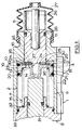
- Figure 1 is a longitudinal section through an hydraulic booster for a vehicle hydraulic system; and
- Figure 2 is similar to Figure 1, but shows a modified booster.
- The hydraulic booster shown in Figure 1 comprises a housing 1 provided with a
longitudinal stepped bore 2, an inlet 3 for connection to a source of hydraulic pressure, suitably a pump or an accumulator (not shown) and anoutlet 4 for connection to a reservoir for fluid (not shown). An input member in the form of apiston 5 works in asmaller diameter portion 6 of thebore 2, and a boost piston 7 for actuating a master cylinder 8 (only part of which is shown) works in a larger diameter portion 9 of thebore 2. The boost piston 7 is advanced in the bore portion 9 in response to pressurisation of aboost chamber 10 by fluid from the source. Pressurisation of theboost chamber 10 is controlled by control valve means 11 operated in response to an input load applied to theinput piston 5. The control valve means 11 comprises a single normally-closedinlet valve 12 controlling communication between the inlet 3 and theboost chamber 10, and variable restriction means 13 operated by relative movement of the boost piston 7 and theinput piston 5 to control fluid flow from theboost chamber 10 to theoutlet 4 via aconnection 14 in the boost piston 7 and aforward chamber 15 defined in the bore portion 9. Theboost chamber 10 is also connected to theforward chamber 15 by passage means 16 in the boost piston 7, with one-way valve means 17 allowing fluid flow through the passage means 16 from theforward chamber 15 to theboost chamber 10. - A
single inlet passage 18 in the housing 1 leads from the inlet 3 to the bore portion 9. The inlet valve means 12 comprises a first, rearward,seal 19 on the boost piston 7 controlling communication between thepassage 18 and theboost chamber 10. Thevalve 12 is closed when the booster is inoperative, so that the booster is then of the closed centre type, and opens on movement of the boost piston 7. A second,forward seal 20 is also provided on the boost piston 7 between thepassage 18 and theoutlet 4, and has a leak path (not shown) to allow slight flow of fluid from thepassage 18 to theoutlet 4. Theseals seal 20 having a groove (not shown) in the PTFE ring 21 to provide the leak path. These seals are particularly suitable for use in high pressure systems, as they have low hysteresis characteristics, and they also have good wear characteristics, so that thefirst seal 19 will not be readily damaged, even though it passes over thepassage 18 to open and close theinlet valve 12. Furthermore, theseseals seals high pressure annulus 23 will normally be defined round the boost piston 7 between theseals seal 20 is provided to ensure that the pressure in theannulus 23 does not become excessive, for example due to thermal expansion of the fluid, as this could result in failure of the boost piston 7 to operate properly. - The variable restriction means 13 comprises a
forward portion 24 on theinput piston 5 cooperating with aseat 25 on the boost piston 7 to restrict flow through theconnection 14, which comprises a central through-bore in the piston 7. - The
input piston 5 is operated by a pedal (not shown) through a push-rod 26 which is sealed to the housing 1 by aboot 27. Theinput piston 5 carries aseal 28 and has a shoulder 29 at its forward end which engages with thestep 30 between thebore portions 6 and 9 to define its retracted position. The boost piston 7 acts on amaster cylinder piston 31 at its forward end. The boost piston 7 andinput member 5 are biassed into the retracted positions shown, in which they are in engagement, by aspring 32 which acts between the boost piston 7 and part of themaster cylinder housing 33. - The passage means 16 in the boost piston 7 comprises a plurality of circumferentially-spaced
longitudinal apertures 34. The one-way valve means 17 has avalve member 35 adapted to control fluid flow through all theapertures 34. Thevalve member 35 comprises an annulus which floats in arecess 36 formed in the rear of the boost piston 7. Theannulus 35 has acentral aperture 37 accommodating theseating portion 25 of the boost piston 7, asolid sealing portion 38 adapted to engage with theapertures 34, and a slotted outer portion 39 which allows fluid flow when the valve means 17 is open. Theannulus 35 closes theapertures 34 when the pressure in the boost chamber 7 exceeds that in theforward chamber 15, but otherwise allows flow between the chambers. - In the inoperative position shown the
inlet valve 12 is closed so that theboost chamber 10 is cut off from the source, but is connected to theoutlet 4 through the one-way valve means 17 and theforward chamber 15. The booster, when inoperative, is therefore of the closed centre type. - In operation, a load is applied to the
input piston 5 from the pedal. Theinput piston 5 and the boost piston 7 are advanced together against the force in thespring 32. Initial movement of the boost piston 7 increases the volume of theboost chamber 10, tending to create a void, and also starts to generate pressure in theforward chamber 15. The resulting pressure differential between the chambers causes fluid to flow from thechamber 15 to thechamber 10 through theapertures 34 and past theopen valve member 35. The pressure in theforward chamber 15 is reduced, while the void in theboost chamber 10 starts to fill. - Further movement of the boost piston 7 then opens the
inlet valve 12, allowing fluid from the inlet 3 into theboost chamber 10, to start to pressurise it. Once the pressure in theboost chamber 10 exceeds that in theforward chamber 15 the one-way valve 17 closes. Pressurisation of theboost chamber 10 advances the boost piston 7 relative to theinput piston 5, and therestriction 13 then operates to control flow through thebore 14, controlling the boost pressure in accordance with the input load. The boost piston 7 acts to operate themaster cylinder 8. The pressure in theboost chamber 10 also acts on theinput piston 5 to provide a reaction, or feel, at the pedal. This reaction starts with the initial fluid flow into theboost chamber 10, and because of the initial flow there is then a smooth transition when theinlet valve 12 opens, with little or no "kick-back" to the operator. - When the force generated by the boost pressure acting on the
input piston 5 equals the applied load, the input and boost pistons separate slightly and the booster is then in its balanced position. - When the input load is reduced, the boost pressure acts to move the
input piston 5 rearwardly, opening therestriction 13 to allow more fluid flow through thebore 14 to reduce the boost pressure. The boost piston 7 is then moved rearwardly by thespring 32 and the reaction from themaster cylinder 8. If the input load is not removed altogether, the booster adopts a new balanced position, otherwise the parts return to the retracted position shown. - It will be noted that in operation the booster acts as an open centre type booster, due to the continuous flow of fluid from the inlet 3 to the
outlet 4. The booster may be used in a twin master cylinder and booster assembly as part of the hydraulic braking system for an agricultural vehicle. - The booster shown overcomes the various disadvantages that arise when the inlet valve is operated by the boost piston 7 rather than the
input piston 5. Normally in this situation servo assistance tends to be initiated relatively slowly, so on initial operation of the booster there is a lack of response, and feel for the operator. With this booster, firstly there is no lost-motion between the input and boost pistons on initial operation, so that the delay in initiating servo assistance is minimised. Furthermore, the reduction in pressure in theforward chamber 15 because of the fluid flow to theboost chamber 10 improves the response of the booster, and this fluid flow also improves the feel for the operator. - Figure 2 shows a modified version of the booster of Figure 1, and corresponding reference numerals have been applied to corresponding parts. In Figure 2 the length of the boost piston 7 is increased to provide an improved bearing surface. The
forward seal 20 is located adjacent therearward seal 19, rather than at the forward end of the boost piston 7, which is instead provided with an annulus 40 and aradial passage 41, to ensure that thereservoir port 4 remains in communication with theforward chamber 15 when the boost piston 7 is at maximum stroke. Theannulus 23 is omitted, but the groove is still provided in the PTFE ring 21 of theforward seal 20, to ensure there is no pressure build-up between the seals. - The arrangement of the
recess 36 for thevalve member 35 is also modified. For ease of manufacture, acirclip 42 round theseat portion 25, rather than the inwardly-extending shoulder on the boost piston, defines the rearward stop for thevalve member 35. Theinput piston 5 is also provided with forwardly extendingprojections 43 which act to break up the fluid flowing into theboost chamber 10 from the inlet, to ensure that the boost piston 7 does not stick in the bore. - The remainder of the construction, and the operation of the booster of Figure 2 are the same as that of Figure 1. The modifications of Figure 2 facilitate manufacture, and improve operation.
- In a further modification, not shown, the passage means 16 and one-way valve means 17 may be of any other suitable type. In yet another modification, not shown, the single inlet valve means 12 may be provided by spool valve portions on the
bore 2 and boost piston 7, but this tends to increase the cost of manufacturing the booster.
Claims (8)
- An hydraulic booster for a vehicle hydraulic system, comprising a housing (1) provided with a bore (2), an inlet (3) for connection to a source of hydraulic pressure, an outlet (4) for connection to a reservoir for fluid, an input member (5) and a boost piston (7) working in the bore (2), the boost piston (7) being advanced in the bore (2) in response to pressurisation of a boost chamber (10) by fluid from the source, a connection (14,15) between the boost chamber and the outlet (4), with pressurisation of the boost chamber (10) being controlled by control valve means (11) operable in response to an input load applied to the input member (5), the control valve means (11) having normally closed inlet valve means (12) controlling communication between the inlet (3) and the boost chamber (10), and variable restriction means (13) operated by relative movement of the boost piston (7) and the input member (5) to control fluid flow from the boost chamber (10) to the outlet (4) through the connection (14,15), characterised in that the inlet valve means comprises a single valve (12) operated by movement of the boost piston (7) in response to movement of the input member (5), and the boost piston (7) includes passage means (16) connecting the boost chamber (10) to a chamber (15) forward of the boost piston (7), and a one-way valve means (17) to allow fluid to flow through the passage means (16) from the forward chamber (15) to the boost chamber (10), on initial movement of the boost piston (7) before the inlet valve (12) opens.
- An hydraulic booster as claimed in Claim 1, in which the single inlet valve (12) is provided by spool valve portions on the bore (2) and the boost piston (7).
- An hydraulic booster as claimed in Claim 1, in which the single inlet valve (12) comprises sealing means (19) on the boost piston (7) co-operating with the inlet (3).
- An hydraulic booster as claimed in Claim 3, in which a second sealing means (20) is provided on the boost piston (7) to prevent flow from the inlet (3) to the outlet (4).
- An hydraulic booster as claimed in Claim 3, in which a second sealing means (20) is provided on the boost piston (7), the sealing means (20) having a leak path to allow slight fluid flow from the inlet (3) to the outlet (4).
- An hydraulic booster as claimed in any preceding claim, in which the passage means (16) in the boost piston (7) comprises a plurality of longitudinal apertures (34).
- An hydraulic booster as claimed in Claim 6, in which the one-way valve means (17) comprises a disc (35) adapted to close all the apertures (34).
- An hydraulic booster as claimed in Claim 7, in which the disc (35) is housed in a recess (36) in the boost piston (7), and has a sealing portion (38) adapted to close the apertures (34), and an apertured portion (39) to allow fluid flow when the one-way valve means (17) is open.
Applications Claiming Priority (2)
| Application Number | Priority Date | Filing Date | Title |
|---|---|---|---|
| GB898901302A GB8901302D0 (en) | 1989-01-20 | 1989-01-20 | Improvements in hydraulic boosters for vehicles |
| GB8901302 | 1989-11-01 |
Publications (3)
| Publication Number | Publication Date |
|---|---|
| EP0379352A2 EP0379352A2 (en) | 1990-07-25 |
| EP0379352A3 EP0379352A3 (en) | 1990-11-07 |
| EP0379352B1 true EP0379352B1 (en) | 1993-12-29 |
Family
ID=10650359
Family Applications (1)
| Application Number | Title | Priority Date | Filing Date |
|---|---|---|---|
| EP19900300479 Expired - Lifetime EP0379352B1 (en) | 1989-01-20 | 1990-01-17 | Improvements in hydraulic boosters for vehicles |
Country Status (3)
| Country | Link |
|---|---|
| EP (1) | EP0379352B1 (en) |
| DE (1) | DE69005462T2 (en) |
| GB (1) | GB8901302D0 (en) |
Family Cites Families (3)
| Publication number | Priority date | Publication date | Assignee | Title |
|---|---|---|---|---|
| DE2016702C3 (en) * | 1970-04-08 | 1974-12-12 | Trw Inc., Cleveland, Ohio (V.St.A.) | Anti-lock device for a hydraulic vehicle brake |
| DE3006610A1 (en) * | 1980-02-22 | 1981-08-27 | Zahnradfabrik Friedrichshafen Ag, 7990 Friedrichshafen | HYDRAULIC BRAKE POWER AMPLIFIER |
| GB2121900B (en) * | 1982-06-11 | 1985-10-23 | Lucas Ind Plc | Hydraulic boosters for vehicles |
-
1989
- 1989-01-20 GB GB898901302A patent/GB8901302D0/en active Pending
-
1990
- 1990-01-17 EP EP19900300479 patent/EP0379352B1/en not_active Expired - Lifetime
- 1990-01-17 DE DE1990605462 patent/DE69005462T2/en not_active Expired - Fee Related
Also Published As
| Publication number | Publication date |
|---|---|
| DE69005462T2 (en) | 1994-04-14 |
| EP0379352A2 (en) | 1990-07-25 |
| DE69005462D1 (en) | 1994-02-10 |
| EP0379352A3 (en) | 1990-11-07 |
| GB8901302D0 (en) | 1989-03-15 |
Similar Documents
| Publication | Publication Date | Title |
|---|---|---|
| US4433543A (en) | Power-operated boosters | |
| US3148592A (en) | Hydraulic brake booster | |
| US3831491A (en) | Brake booster | |
| US3935709A (en) | Dual power brake booster | |
| US6550245B2 (en) | Hydraulic brake apparatus for a vehicle | |
| EP0225212B1 (en) | Hydraulic brake booster with quick take-up and reduced stroke | |
| JPS62181951A (en) | Tandem master cylinder with booster | |
| US4468927A (en) | Hydraulic boosters for vehicle braking systems | |
| JPH0313105B2 (en) | ||
| EP0428320B1 (en) | Hydraulic pressure control system | |
| US4198823A (en) | Method of generating brake actuating pressure | |
| US4220007A (en) | Servo-assisted hydraulic master cylinder | |
| US3877227A (en) | Supported line pressure power brake assembly | |
| US4199948A (en) | Dual power brake booster | |
| US3939658A (en) | Power brake booster | |
| US4199940A (en) | Dual power brake booster and method of generating brake actuating pressure | |
| EP0379352A2 (en) | Improvements in hydraulic boosters for vehicles | |
| US4474004A (en) | Power-operated boosters | |
| US5065580A (en) | Tandem master cylinder with limited-motion booster piston at pedal-remote end of master cylinder and with booster fluid cut valve | |
| EP0517363B1 (en) | Improvements in master cylinder and booster assemblies | |
| GB2077375A (en) | Improvements in power- operated boosters | |
| US4783965A (en) | Hydraulic booster | |
| GB2111620A (en) | Deceleration-sensing modulator valve assembly for vehicle braking systems | |
| US6607254B2 (en) | Hydraulic brake device | |
| US4704867A (en) | Hydraulic brake booster with cam and lever ratio changer |
Legal Events
| Date | Code | Title | Description |
|---|---|---|---|
| PUAI | Public reference made under article 153(3) epc to a published international application that has entered the european phase |
Free format text: ORIGINAL CODE: 0009012 |
|
| AK | Designated contracting states |
Kind code of ref document: A2 Designated state(s): DE FR GB |
|
| PUAL | Search report despatched |
Free format text: ORIGINAL CODE: 0009013 |
|
| AK | Designated contracting states |
Kind code of ref document: A3 Designated state(s): DE FR GB |
|
| 17P | Request for examination filed |
Effective date: 19901219 |
|
| 17Q | First examination report despatched |
Effective date: 19920124 |
|
| GRAA | (expected) grant |
Free format text: ORIGINAL CODE: 0009210 |
|
| AK | Designated contracting states |
Kind code of ref document: B1 Designated state(s): DE FR GB |
|
| REF | Corresponds to: |
Ref document number: 69005462 Country of ref document: DE Date of ref document: 19940210 |
|
| ET | Fr: translation filed | ||
| PLBE | No opposition filed within time limit |
Free format text: ORIGINAL CODE: 0009261 |
|
| STAA | Information on the status of an ep patent application or granted ep patent |
Free format text: STATUS: NO OPPOSITION FILED WITHIN TIME LIMIT |
|
| 26N | No opposition filed | ||
| REG | Reference to a national code |
Ref country code: FR Ref legal event code: TP |
|
| REG | Reference to a national code |
Ref country code: GB Ref legal event code: IF02 |
|
| REG | Reference to a national code |
Ref country code: GB Ref legal event code: 732E |
|
| REG | Reference to a national code |
Ref country code: GB Ref legal event code: 732E |
|
| REG | Reference to a national code |
Ref country code: FR Ref legal event code: TP |
|
| REG | Reference to a national code |
Ref country code: GB Ref legal event code: 732E |
|
| REG | Reference to a national code |
Ref country code: FR Ref legal event code: TP |
|
| PGFP | Annual fee paid to national office [announced via postgrant information from national office to epo] |
Ref country code: GB Payment date: 20061213 Year of fee payment: 18 |
|
| PGFP | Annual fee paid to national office [announced via postgrant information from national office to epo] |
Ref country code: DE Payment date: 20070131 Year of fee payment: 18 |
|
| PGFP | Annual fee paid to national office [announced via postgrant information from national office to epo] |
Ref country code: FR Payment date: 20070103 Year of fee payment: 18 |
|
| GBPC | Gb: european patent ceased through non-payment of renewal fee |
Effective date: 20080117 |
|
| PG25 | Lapsed in a contracting state [announced via postgrant information from national office to epo] |
Ref country code: DE Free format text: LAPSE BECAUSE OF NON-PAYMENT OF DUE FEES Effective date: 20080801 |
|
| REG | Reference to a national code |
Ref country code: FR Ref legal event code: ST Effective date: 20081029 |
|
| PG25 | Lapsed in a contracting state [announced via postgrant information from national office to epo] |
Ref country code: GB Free format text: LAPSE BECAUSE OF NON-PAYMENT OF DUE FEES Effective date: 20080117 |
|
| PG25 | Lapsed in a contracting state [announced via postgrant information from national office to epo] |
Ref country code: FR Free format text: LAPSE BECAUSE OF NON-PAYMENT OF DUE FEES Effective date: 20080131 |