EP0377392A2 - Method for conferencing a phone call and terminal displayed information associated with it - Google Patents
Method for conferencing a phone call and terminal displayed information associated with it Download PDFInfo
- Publication number
- EP0377392A2 EP0377392A2 EP89480176A EP89480176A EP0377392A2 EP 0377392 A2 EP0377392 A2 EP 0377392A2 EP 89480176 A EP89480176 A EP 89480176A EP 89480176 A EP89480176 A EP 89480176A EP 0377392 A2 EP0377392 A2 EP 0377392A2
- Authority
- EP
- European Patent Office
- Prior art keywords
- call
- phone
- extension
- communication
- terminal
- Prior art date
- Legal status (The legal status is an assumption and is not a legal conclusion. Google has not performed a legal analysis and makes no representation as to the accuracy of the status listed.)
- Granted
Links
- 238000000034 method Methods 0.000 title claims abstract description 31
- 238000012546 transfer Methods 0.000 claims abstract description 48
- 238000004891 communication Methods 0.000 claims description 72
- 230000006854 communication Effects 0.000 claims description 72
- 238000012545 processing Methods 0.000 claims description 35
- 230000004044 response Effects 0.000 claims description 5
- 230000006870 function Effects 0.000 description 57
- 238000007726 management method Methods 0.000 description 18
- 230000000694 effects Effects 0.000 description 15
- 238000010586 diagram Methods 0.000 description 12
- 230000008569 process Effects 0.000 description 9
- 230000009471 action Effects 0.000 description 7
- 238000004458 analytical method Methods 0.000 description 5
- 230000008859 change Effects 0.000 description 5
- 238000001514 detection method Methods 0.000 description 5
- 238000013459 approach Methods 0.000 description 4
- 230000008901 benefit Effects 0.000 description 4
- 230000005540 biological transmission Effects 0.000 description 4
- 238000012544 monitoring process Methods 0.000 description 4
- 230000002093 peripheral effect Effects 0.000 description 4
- 238000003860 storage Methods 0.000 description 4
- 238000012360 testing method Methods 0.000 description 4
- 238000010200 validation analysis Methods 0.000 description 4
- 238000004883 computer application Methods 0.000 description 3
- 238000009826 distribution Methods 0.000 description 3
- 238000011084 recovery Methods 0.000 description 3
- HCHKCACWOHOZIP-UHFFFAOYSA-N Zinc Chemical compound [Zn] HCHKCACWOHOZIP-UHFFFAOYSA-N 0.000 description 2
- 238000007792 addition Methods 0.000 description 2
- 230000000875 corresponding effect Effects 0.000 description 2
- 238000013461 design Methods 0.000 description 2
- 238000005516 engineering process Methods 0.000 description 2
- 230000006872 improvement Effects 0.000 description 2
- 230000007257 malfunction Effects 0.000 description 2
- 238000012986 modification Methods 0.000 description 2
- 230000004048 modification Effects 0.000 description 2
- 238000003825 pressing Methods 0.000 description 2
- 238000005070 sampling Methods 0.000 description 2
- 230000007704 transition Effects 0.000 description 2
- 238000013024 troubleshooting Methods 0.000 description 2
- 230000000712 assembly Effects 0.000 description 1
- 238000000429 assembly Methods 0.000 description 1
- 238000013475 authorization Methods 0.000 description 1
- 230000006399 behavior Effects 0.000 description 1
- 230000002457 bidirectional effect Effects 0.000 description 1
- 230000000295 complement effect Effects 0.000 description 1
- 230000001276 controlling effect Effects 0.000 description 1
- 238000001816 cooling Methods 0.000 description 1
- 238000012937 correction Methods 0.000 description 1
- 238000013479 data entry Methods 0.000 description 1
- 238000003066 decision tree Methods 0.000 description 1
- 230000001419 dependent effect Effects 0.000 description 1
- 230000000881 depressing effect Effects 0.000 description 1
- 230000005611 electricity Effects 0.000 description 1
- 230000008030 elimination Effects 0.000 description 1
- 238000003379 elimination reaction Methods 0.000 description 1
- 230000000977 initiatory effect Effects 0.000 description 1
- 238000012423 maintenance Methods 0.000 description 1
- 238000013507 mapping Methods 0.000 description 1
- 238000002360 preparation method Methods 0.000 description 1
- 230000011664 signaling Effects 0.000 description 1
- 230000003068 static effect Effects 0.000 description 1
- 230000009897 systematic effect Effects 0.000 description 1
- 230000001960 triggered effect Effects 0.000 description 1
- 210000003954 umbilical cord Anatomy 0.000 description 1
- 230000000007 visual effect Effects 0.000 description 1
Images


Classifications
-
- H—ELECTRICITY
- H04—ELECTRIC COMMUNICATION TECHNIQUE
- H04M—TELEPHONIC COMMUNICATION
- H04M3/00—Automatic or semi-automatic exchanges
- H04M3/42—Systems providing special services or facilities to subscribers
- H04M3/56—Arrangements for connecting several subscribers to a common circuit, i.e. affording conference facilities
- H04M3/567—Multimedia conference systems
-
- H—ELECTRICITY
- H04—ELECTRIC COMMUNICATION TECHNIQUE
- H04M—TELEPHONIC COMMUNICATION
- H04M3/00—Automatic or semi-automatic exchanges
- H04M3/42—Systems providing special services or facilities to subscribers
- H04M3/50—Centralised arrangements for answering calls; Centralised arrangements for recording messages for absent or busy subscribers ; Centralised arrangements for recording messages
- H04M3/51—Centralised call answering arrangements requiring operator intervention, e.g. call or contact centers for telemarketing
-
- H—ELECTRICITY
- H04—ELECTRIC COMMUNICATION TECHNIQUE
- H04M—TELEPHONIC COMMUNICATION
- H04M2203/00—Aspects of automatic or semi-automatic exchanges
- H04M2203/50—Aspects of automatic or semi-automatic exchanges related to audio conference
- H04M2203/5018—Initiating a conference during a two-party conversation, i.e. three-party service or three-way call
-
- H—ELECTRICITY
- H04—ELECTRIC COMMUNICATION TECHNIQUE
- H04Q—SELECTING
- H04Q2213/00—Indexing scheme relating to selecting arrangements in general and for multiplex systems
- H04Q2213/13072—Sequence circuits for call signaling, ACD systems
-
- H—ELECTRICITY
- H04—ELECTRIC COMMUNICATION TECHNIQUE
- H04Q—SELECTING
- H04Q2213/00—Indexing scheme relating to selecting arrangements in general and for multiplex systems
- H04Q2213/13175—Graphical user interface [GUI], WWW interface, visual indication
-
- H—ELECTRICITY
- H04—ELECTRIC COMMUNICATION TECHNIQUE
- H04Q—SELECTING
- H04Q2213/00—Indexing scheme relating to selecting arrangements in general and for multiplex systems
- H04Q2213/1322—PBX
-
- H—ELECTRICITY
- H04—ELECTRIC COMMUNICATION TECHNIQUE
- H04Q—SELECTING
- H04Q2213/00—Indexing scheme relating to selecting arrangements in general and for multiplex systems
- H04Q2213/1324—Conference call
Definitions
- This invention relates to improvements in data processing applications in a multi-user environment and, more particularly, to a method, involving a digital switch and a host, for conferencing a phone call and Terminal displayed information associated with it.
- the display terminal also provided a useful repository of information for the employee.
- a client could call to obtain a current quotation on a stock portfolio.
- the client might also request prospectus information on other possible investments.
- the employee could access a host database to acquire the stock information; and, if the client wanted to place an order for additional stock, the employee could transfer the call to a broker. However, the broker would have to access the same information again that the other employee had before him on the display terminal before transferring the call.
- Vij patent discloses a method for providing a directory number to a sales person engaged in telemarketing to increase the efficiency of outbound telemarketing personnel.
- This patent provides no teaching of transferring information associated with a call to another interested party in conjunction with the transfer of the call. Also, there is no teaching of shared access to information associated with a telephone call that is already active.
- these objects are accomplished by configuring a set of host data structures to link phone extensions to particular display terminals attached to the host and a particular Customer Information Control System (CICS) application.
- the data structures also contain information regarding the appropriate transfer of information from the host application to the phone extension across a network of digital switches.
- additional data structures are provided to facilitate shared access to voice and data extensions.
- CBX and host have communication managers to facilitate the transfer of messages using a standard protocol. Also, a standard application manager is used to coordinate the activities of the system programs and other preexisting applications. The status of each call is carefully tracked by the system programs and recorded in logs for later analysis.
- the Computerized Branch Exchange (CBX) 1 is the digital switch that manages the telephone processing.
- the CBX 1 interfaces to the host 3 via an Logical Unit (LU) 6.2 interface 2.
- LU Logical Unit
- the CBX 1 translates the request into a corresponding host display terminal transfer request transaction from terminal display 5 to display terminal 7.
- the transaction is built and sent from the CBX 1 through the LU 6.2 link 2 to the host 3.
- the host 3 performs a table lookup to determine the terminal display 7 associated with the new phone extension 6. Then, the current display transaction that is displayed on the transferror terminal display 5 is displayed on the new terminal display 7.
- a more detailed analysis of the processing is disclosed below.
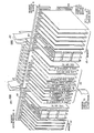
- FIG 2 An example of a prior art CBX, similar to the preferred embodiment, is provided in Figure 2, which illustrates the computer control equipment associated with the prior art ROLM CBX II 9000.
- the hardware consists of redundant memory 10, a shared, switched I/O bus (ISB) 20, various interface cards 30, disk 40, and redundant processors 50.
- ISB switched I/O bus
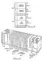
- INL Inter Node Link
- Shelf one 51 is a common control shelf in a redundant system cabinet or another Time Division Multiplex (TDM) card shelf in a nonredundant system cabinet. Shelf two 52 is always a common control shelf. Shelves three 53 and four 54 are always TDM card shelves. Air cooling systems and redundant power systems are provided at 55 to dissipate heat and provide system power.
- TDM Time Division Multiplex
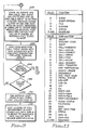
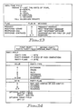
- FIG 4 illustrates the CPU shelf slots of the common control slot 52.
- memory-cards 60 there are memory-cards 60, processor set 61, shared input/ output (I/O) hardware 62, and disk drive units 63.
- the processor cards contain the microprocessors.
- the common control motherboard 64 is used to join the other common control motherboard from the redundant common control shelf 51 and the TDM shelves 53 and 54.
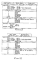
- FIG. 5 shows the TDM shelf slots.
- the TDM communication cards fit into the slots shown at 65.
- the other TDM cards occupy the slots at 68.
- Slot 70 is reserved for Line Shelf Monitor LSM which monitors the power supply and contains the fuses. If LSM detects a power supply failures or fuse failures, it is reported to error analysis by a scanner reporting a monitor error. Error analysis then parses specific decision trees to generate suggested actions.
- LSM Line Shelf Monitor
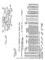
- Figure 6 is a hardware block diagram of the CBX system.
- the figure is a functional representation of the preferred embodiment of the CBX.
- Nodes are the modular building blocks of the CBX system. Each node can function as a stand-alone telecommunication system consisting of the time division multiplexing (TDM) switching network, processors, cabinet and power system, and interface cards.
- TDM time division multiplexing
- a single-node system can expand from one to five equipment cabinets to accommodate up to 2,000 lines.
- the CBX is a digital switching system using TDM and pulse code modulation (PCM) to support a wide range, of voice, data, and specialty applications.
- PCM pulse code modulation
- a 32-bit processor and Random Access Memory (RAM) provide control intelligence within each node.
- Multiplexing is a method of using a single communication channel to carry multiple speech and/or data transmissions simultaneously.
- the TDM channel use is alternated between users or between system functions, each receiving a small portion of channel time (a time slot) in rotation.
- the channel seems to be reserved for each individual transmission, but because of the highspeed channel, it carries many transmissions simultaneously.
- PCM is the process which analog sound waves of voice conversations are sampled, translated into digital signals, transported over the TDM network, and reconstructed into analog signals.
- the CBX samples voice signals at 8,000 times per second. The samples are converted into 8-bit binary words, which are transmitted over the data bus.
- Bus is the entire TDM switching network. It maintains the connections established by the processor and passes information between the common control electronics and the telephones, terminals, and trunks.
- the bus is the vehicle for intranode communication.
- the bus is a 16-bit, parallel, unidirectional bus that has a capacity of 295 megabits per second (Mbps). It provides 1,152 two-way or full-duplex communication channels, of which 1045 are available for voice/data traffic. The system uses the remaining channels for various control functions, such as setting up phone displays.
- TDM Network Control Group This group consists of the: * Intrashelf Bus 84 * Intershelf bus 86 & 87 * Expander 80 cards * TDM controller cards
- Intrashelf Bus 84 On the back of each TDM shelf is an Intrashelf Bus 84 implemented on the TDM backplane.
- the Intrashelf Bus 84 permits communication within a shelf.
- one Expander 80 card plugs into each Intrashelf Bus 84. Expander 80 cards provide the interface between the Intrashelf Bus 84 and the Intershelf Bus (ISB).
- ISB Intershelf Bus
- Each Intrashelf Bus 84 includes a 16-bit bidirectional data bus, a 10-bit address bus, and an "enable" line to each card.
- the enable line eliminates the need for configuring each card with a particular shelf address, so that interface cards can occupy any slot on the shelf. In addition, the enable line simplifies address decoding, which increases reliability
- ISB is an integral part of the proprietary Bus structure, handles communication among shelves through a flat, ribbon cable attached to the TDM controller (TC 81) card and the Expander 80 cards on each shelf.
- the ISB supports a data rate of 295 Mbps over two unidirectional buses: the source bus 87 and the Destination bus 86.
- Expander 80 cards are also redundant. When one common control side of the cabinet is active, one of the Expander 80 cards is in use, while the redundant (inactive) common control side and other Expander 80 card will wait to become active.
- Each Expander 80 card contains a connection table for all voice and data connections affecting its shelf. This frees intrashelf bandwidth for call data, instead of consuming bandwidth for the address information needed to make connections.
- the Expander 80 cards, TC 81 card, and Turnaround 82 card use the Bus ISB clock (located on the Turnaround 82 card) for timing the Bus traffic. This maintains the correct timing relationship between the data, which travels along the bus, and the clock pulses.
- the turnaround card also sends out a pulse at the beginning of each sampling interval. The pulse tells the Expander 80 card to start again with the first entry in the connection table.
- the Bus TC 81 card maintains supervision of the processor-ISB-interface communication.
- TC 81 cards reside on the common control shelves in cabinet 1 of a CBX node.
- the TC 81 card is responsible for the following three activities: loading and verifying the connection table on each Expander 80; configuring the turnaround card and InterNode Link (INL 83) hardware; and communicating with the various line card groups.
- the TC 81 card handles up to 12 Mbps of control information.
- Control packets contain addressing, control, and data information for loading the Expander 80 connection tables and reading the status of line cards.
- the TC 81 cards maintain a communication path between the two ends of a voice or data call.
- the processor through the TC 81 card, switches digitized signals by assigning them to unique time slots on the ISB.
- the Bud ISB uses TDM techniques, which enable the ISB to carry a large amount of simultaneous voice and data transmission.
- the Turnaround 82 card turns the data around on the bus.
- the Expander 80 card on the transmitting card's shelf places a data word on the source bus 87.
- the data word travels to the right until it encounters the Turnaround 82 card, which receives the word and retransmits it ("turns it around") to the Destination bus 86.
- the Expander 80 on the destination shelf captures the word and sends it on to the proper card.
- the advantage of using the turnaround card is that information retransmitted in an individual time slot to the Destination bus 86 and the receiving card can be complete severelyly different from information received in that time slot from the source bus 87 and the transmitting card. This doubles the traffic capacity of the switch by allowing two internode conversations to take place in a single time slot on the bus.
- the Turnaround 82 card can fill this empty slot with a voice sample from the other end of the conversation. In this way, the signals from both ends of the conversation can occupy the same time slot simultaneously.
- the system clock In each node of a multinode CBX system, the system clock provides timing for the TDM network via the Turnaround 82 card. It also synchronizes INL 83 operation between nodes.
- the source of this clock can be its own internal system, or it can synchronize from an external T1 interface trunk.
- the system clock conforms to Stratum 4 of the Bell Network Synchronization Plan.
- the new Bus provides the CBX with 2,304 timeslots per node.
- Bandwidth is the measure of voice and data traffic capacity in the CBX.
- the clock speed of the Bus 16-bit parallels backplane is 18,432 MHz.
- the CBX offers the advantage of computer common control. With the stored programs of computer common control, it is easy to update features as business needs change. This provides greater flexibility and reduces the cost of feature additions and other changes that may be made in the future.
- the computer common control group directs all activities within the CBX system.
- a single-node CBX supports 1 or 2 common control shelves. Shelf 2 of cabinet 1 always houses a computer common control group. To increase reliability in critical applications or larger systems, shelf 1 can accommodate a second, or redundant, common control group.
- These groups consist of: * Processor * Memory * Enhanced Communications Processor * Disk systems * System Monitor card * I/O card
- the 9000 is a 32-bit processor employed by the CBX. It is a ROLM-proprietary design using powerful, high-speed, bit-slice technology, with a ROLM proprietary instruction set.
- a single node configuration supports from 7,500 to 11,000 Busy Hour Call Attempts (BHCA); that is, the total number of call setups attempted during the hour when the CBX carries the most traffic.
- the processor controlling the system is the active processor; the other one is the standby processor. Either processor can provide standby common control to prevent a failure in the active common control from halting system operation.
- the active processor continually transfers new information, such as moves and changes, Station Speed Calling information, as well as calls-in-progress information to the standby computer. Therefore, in the event of a switchover from the active computer, the standby computer always contains current information regarding the state of the system.
- CBX uses RAM to store all system software. Stored in memory are the system operating software, system-specific configuration parameters, and operating data. Each processor can access up to four memory cards. Each memory card accommodates 1 million words of memory, with each word composed of 16 bits plus 6 Error Correcting Code (ECC) bits. ECC improves the accuracy with which the system memory retains information. By automatically detecting and correcting all memory single-bit errors and detecting most multiple-bit errors, ECC minimizes the likelihood of a system failure due to a malfunctioning memory component.
- ECC Error Correcting Code
- Systems with redundant processors are capable of detecting multiple-bit errors and automatically switching to the redundant computer.
- a hardware register on the memory card enters errors into a table to aid servicing.
- ECC error control code
- Soft errors are intermittent malfunctions, usually of short duration and low frequency, that might result from the execution of specific data patterns, the temperature of the room or static electricity. Soft errors can cause erratic system behavior, forcing service personnel to spend hours troubleshooting a fault that may not exist.
- the error detection and correction capability improves the reliability of the CBX system and eliminates needless hours of "trial and error" troubleshooting
- the Enhanced Communications Processor is a two-card processor that provides improved call setup, a foundation for future data products and applications. Supporting the ECP are the Data Front End (DFE) cards which reside on TDM shelves, and offloads the data call setup messages from the CBX processor. The DFE also allows call setup to occur at the baud rate of the calling device. This facilitates the use of popular PC-based communication packages that permit automatic data call setup.
- DFE Data Front End
- Peripherals housed on shelf 2 consist of two 3.5-inch, 1.44M floppy disks and one 5.25-inch, 40M hard disk, and a peripheral device controller (PDC) card.
- the right-hand end of the shelf contains the disk assemblies.
- IBM provides the CBX System Software, Release 9004.3, and diagnostic programs on floppy disks.
- the floppy disk system stores Initial Program Load (IPL) software, a back-up copy of the current site data base, and software updates (new software releases).
- IPL Initial Program Load
- IPL is a "cold start" that loads information from a floppy disk into the system's main memory and is then written onto the 40M hard disk assembly.
- IBM technicians perform IPL at a customer's site when they install a system.
- the hard disk system contains disk storage media that are sealed from the environment to provide a high degree of reliability.
- the hard disk contains the operating system program. It also has sufficient storage for certain voice and data applications to store information on a real-time basis. For example, the hard disk stores configuration tables, Moves, Adds, and Changes (MAC), and Forced Authorization Codes (FAC).
- MAC Moves, Adds, and Changes
- FAC Forced Authorization Codes
- APL Automatic Program Load
- SMC provides fuse/circuit alarm detection, software alarm detection, temperature alarm detection, power-failure detection, and dc voltage monitoring.
- This printed circuit card resides in one slot of the common control shelf (shelf 2) in both redundant and nonredundant configurations.
- Power-failure indicator LED's located on the SMC, light when voltage drops. LED's also provide a high-temperature warning. Fuse-alarm circuitry generates both visual and audible alarms should a fuse malfunction.
- RSM provides redundant common control shelf status for SMC.
- One RSM resides on the redundant processor shelf (shelf 1) in Models 50 and 70.
- LSM Local Shelf Monitor
- the SMP is a 4-channel maintenance interface that resides on common control shelf 2. Two of the four ports on the SMP are permanently assigned to the system terminal and the system modem.
- the two available ports can support: * Automatic Call Distribution terminals * System administration data link * Call Detail Recording list device
- the Quad Serial I/O card is an optional card used to increase the number of devices a system can support.
- Each Quad Serial I/O card supports up to four devices used for features such as Expanded Traffic Reports, Automatic Call Distribution (ACD) statistics, moves, and changes.
- the Quad Serial I/O card supports the following RS-232-C ASCII devices, which run at data rates of up to 9.6 Kbps: * Modems * Printers or output-only devices * Loaders or input-only devices * "Smart" and "nonintelligent" terminals * Automatic Call Distribution terminals * Interface to the Phonemail Application Processor
- a node consists of one to five connected equipment cabinets.
- the maximum single-node configuration has 5 cabinets and a total of 20 shelves.
- cabinet 1 When viewed from the front, cabinet 1 is on the left with shelves 1 to 4.
- Cabinet 2 When viewed from the front, cabinet 1 is on the left with shelves 1 to 4.
- Cabinet 2 is next with shelves 5 to 8, while cabinet 5 is on the far right with shelves 17 to 20.
- Shelves contain three categories of equipment: computer common control; TDM interface cards for line, data, or trunk interface; and INL 83 for internode communication of voice and data information.
- the CBX is modified to accommodate the CMCS application as follows:
- the host link is a standard System Data Link Control (SDLC) communication link that conforms to the LU 6.2 standard.
- SDLC System Data Link Control
- a detailed description of an LU 6.2 communication link and how to implement a program interface to conform with this standard is provided in the following publications by International Business Machines Corporation: Systems Network Architecture: Sessions Between Logical Units, GC20-1868; SNA Transaction Programmer's Reference Manual For LU Type 6.2, GC30-3084.
- the host hardware is one of the IBM System/370 processors.
- a detailed analysis of the IBM System/370 processor is provided in S/370 Reference Summary, GX20-1850, published by International Business Machines Corporation. While a S/370 host processor is described in the preferred embodiment, those skilled in the art will recognize that the invention can be practiced on other mainframes, minicomputers and microprocessors.
- CMCS application resides in the CBX software application memory.
- the application is invoked by the initiation of any call to a phone that is flagged in the CBX for CMCS event processing.
- the CBX software is responsible for processing information from each flagged extension, managing an SDLC communication link to the host, formatting LU 6.2 transactions and sending the formatted transactions via the SDLC card to the host processor.
- Routing of a phone call is based on standard algorithms in the CBX for the originating call and the final destination of the call. Once the proper routing is determined, a host transaction is formatted and routed through the SDLC card to the host. The format of the various transactions are shown below in the message processing portion of the detailed invention. For more information on the detailed processing of calls, the reader is referred to the ROLM 9004.3 Business Communication System.
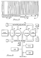
- FIG. 23 provides a software overview of the CMCS system.
- the operating system which manages the other host software and their use of system peripherals, is MVS/XA 2000.
- the host communication manager, ACF/VTAM 2002 interfaces with the operating system and manages the communication between the host and other peripherals such as the CBX 2004.
- CICS/VS 2006 manages the flow of information from application to display terminals.
- the CMCS applications 2010 process the transactions from the CBX 2004 and coordinate the transfer of application 2014 information to the terminals 2015.
- the CMCS 2010 and user 2014 applications are all CICS application programs.
- the interface to the user applications from CMCS 2010 is the Application Programming Interface (API) 2018.
- CMCS 2010 Systems Operations manages the CMCS 2010 system through the operations interface (OI) 2016 and an attached CMCS console 2012.
- the CMCS console 2012 allows support personnel to track system operation and run queries against the three system files.
- the system tables and logs are: configuration 2024, log 2022 and management information services (MIS) 2020. The system tables are discussed in detail below.
- the preferred operat ing system is Multiple Virtual Systems / Extended Architecture 2000 which is a multiple task, multiple user environment for execution on the newest of IBM's S/370 processors.
- the details of the operating system are described in MVS/XA OLTEP LOGIC, SY28-1188 and MVS/XA Logic VOLUMES 1-17, published by International Business Machines.
- ACF/VTAM 2002 is the communication monitor that executes under the control of the operating system and controls the communication link to the CBX and each terminal that is attached to the host.
- VTAM controls the Systems Network Architecture (SNA) environment that supports the LU 6.2 protocol.
- SNA Systems Network Architecture
- a detailed description of VTAM is provided in the following references all published by International Business Machines Corporation: VTAM NCP SNA SNI NLDM SSP NCCF, SC27-0659; IMS LU 6.1 Adapter for LU 6.2 Applications, SH20-9254; Systems Network Architecture: Sessions Between Logical Units, GC20-1868; SNA Transaction Programmer's Reference Manual For LU Type 6.2, GC30-3084.
- CICS 2006 is a general purpose data communication monitor that reduces the effort necessary to implement terminal-oriented transaction applications.
- CICS is used around the world to enable applications, ranging from payroll to inventory control, to interactively handle a large number of displays.
- CICS/VS Customer Information Control System/Virtual Storage
- GC33-0155-1 published by International Business Machines Corporation.
- a more detailed description of the logic of CICS is provided in CICS/OS/VS Version 1 Release 7 Modification 0 (MVS/XA Feature) Listings, LYA4-3018; and CICS/VS, LIC Prog 5740-xx1, Logic, LY33-6034; published by International Business Machines Corporation.
- the CMCS applications 2010 and the User applications 2014 are all implemented as CICS application programs.
- the user applications 2014 interface to CMCS through the Application Programming Interface (API) 2018.
- An application program can acquire status information and access the CMCS logs 2020, 2022 & 2024 through the API. This information can be used to coordinate the display of information from application programs in addition to the information displayed by the CMCS system.
- Initial Screen is the first screen that the CMCS agent gets when a call is processed. Once the CMCS agent enters the customer identification, such as an account number or a name, the screen becomes a customer information display.
- Customer Information Screen is the screen that a CMCS agent gets if the call has already been screened by another employee.
- Normal Extension is an extension that has a physical appearance to a phone, as contrasted with ACD pilots or Phonemail pilots.
- Extension is considered the extension normally associated with a phone (normal extension) unless a qualifier appears before extension.
- CMCS caller is a trunk or extension that calls a CMCS called party.
- CMCS called party is an extension, an ACD agent, an ACD group, an ATC, or trunk which generates CMCS telephony activity events.
- CMCS agent refers to the operator, phone and host display terminal associated with a particular agent.
- Telephone activity is any call activity that occurs on a CMCS called party extension, for example: ring a CMCS called party or queue for an ACD group tagged as a CMCS called party.
- Flagged CMCS called party is a CMCS called party which has the ability to turn CMCS event generation on for all subsequent telephony activity.
- CMCS event is the first CMCS event with special initial call flag set in the event that is sent when a CMCS caller has telephony activity with any flagged CMCS called party for the first time.
- target extensions are tagged as CMCS.
- a target extension is equivalent to a CMCS called party. If a caller has telephony activity with a CMCS called party, then the caller is tagged as a CMCS caller. This is a dynamic tag and remains active until the CMCS caller becomes idle.
- CMCS callers can be trunks or normal extensions exclusively.
- CMCS called parties can be ACD group pilots, normal extensions, ATCs, and trunks.
- Only one display terminal is associated with the activity of an individual extension. For example, suppose that an extension has multiple appearances on two phones. Then, any telephony activity on those two phones with that extension affect the display of information on the display terminal.
- a CMCS called party that is being rung by a CMCS caller is presented with the initial customer screen or the customer information display terminal screen that the previous CMCS called party was viewing. Also, as a CMCS caller transfers forward to other CMCS called parties, the display terminal of each successive CMCS called party is updated with either the initial screen or the customer information screen.
- a blind transfer is a special type of transfer which transfers the display terminal screen that the CMCS called party (transferrer) was viewing to the transferred CMCS party while the call is ringing. This allows the agent some additional preparation time before answering the call.
- FIG. 23 is an overview block diagram of the CMCS application environment as they relate to the present invention.
- the call tracking application program includes the LU 6.2 communication manager.
- the primary function of call tracking is to maintain the call status on the event stream and resolve any ambiguities before reporting events to other applications. If call tracking determines that a transaction associated with an originating source identification (extension) needs updating, it refers the event to the Screen Update program. Queued events and events regarding source identification which contributed to a queue count are passed to ACD load balancing.
- Screen update application program performs screen transfer, initialization and recovery for each call. The processing is triggered by events on the CMCS host control link which the call tracking program passes to it.
- CMCS MIS program receives the CMCS table entries maintained for each call tracking every change of state, data entry field and queue count.
- the CMCS MIS program puts these records into a circular buffer 2020 of Figure 23 to store the information for other applications to process.
- This program processes the CMCS table entries to allow a CMCS operator to interrogate error conditions and monitor events on CBX source and target identifications (extensions). This program also configures the CMCS system and maintains the configuration file 2024 of Figure 23.
- CMCS customer applications are any CICS application programs. For purposes of our discussion, we will discuss a single CMCS customer application program that maintain a database of customer information for CMCS agents. In reality, there are many CICS applications currently used for such diverse applications as accounts payable, accounts receivable, inventory control, stock queries and order entry. By providing an interface to existing applications, CMCS coordinates the display of information on a display terminal with the transfer of phone calls without changing existing CICS applications.
- CMCS complementary metal-oxide-semiconductor
- the processing begins at function block 500 where the CBX responds to the incoming call.
- This function block refers to normal CBX call processing as detailed in ROLM publication, ROLM CBX II 9004.3, published by International Business Machines Corporation.
- the CBX accepts the network dialing that accompanies the call and determines the correct extension to connect to. This is also normal call processing as described above. However, in function block 520, the CBX generates a call event transaction and sends it via the LU 6.2 link to the host as detailed in the Message Formats section of the Logic Description.
- the host Call Tracking Application receives the call event, parses the information and determines if this is the first event for the extension. If it is the first event, then a call event record is created in the Call Management Control Table (CMCT), shown in Figure 18. The call event record is updated to reflect each event that affects the extension. Then, the initial screen to be displayed is determined using the incoming trunk and/or the target phone extension as shown in function block 530.
- CMCT Call Management Control Table
- the Call Tracking Application uses the phone extensions sent from the CBX to access an extension to terminal (logical unit address (LUA)) table and determine the correct display terminal to send the screen display to.
- LOA logical unit address
- the extension to terminal (LUA) table is shown in Figure 19.
- the network used in this example contains terminal displays and phone extensions from countries around the world.
- the only information necessary to make the connections to the various extensions and send the display information to the correct display terminal is contained in the extension to terminal (LUA) table.
- the extension to terminal (LUA) table is searched based on the sixteen byte extension of the called party to obtain the terminal LUA associated with the phone call. When a match is found between the sixteen byte extension and the first sixteen bytes of a record, the next twenty-four bytes of the record is the LUA of the associated display terminal. The host application then knows which display terminal to send the screen information to.
- the CMCS Customer Application sends the initial terminal display to the display terminal, as shown in function block 540.
- the display terminal LUA is determined by the Call Tracking Program by searching the extension to terminal (LUA) table and acquiring the correct LUA for the associated display terminal as discussed above in reference to function block 530.
- the agent who receives the call and the information on the display terminal has the option of entering additional information on the display terminal to further enhance the customer information as shown in function block 550. If the caller requests additional services that require the help of another agent, then the agent can transfer the caller using the standard call transfer features of the phone as shown in function block 560.
- a test is performed at decision block 570 to determine if another agent is available in the group that is being transferred to. If an agent is not available, then control is transferred to a queue for callers that is discussed in more detail later. If an agent is available, the CBX connects the caller to the other agent and sends a call event transaction through the LU 6.2 link to the host as shown in function block 580.
- the transaction contains the same source identification as the previous transaction, but now it also contains the phone extension of the agent that the call is transferred to.
- the host receives the call event from the CBX and identifies the caller by the same source identification and matches the new target extension to the terminal LUA as discussed above by a table lookup. Then, the host CMCS screen transfer program transfers the terminal transaction associated with the previous terminal to the new terminal LUA as shown in function block 600. As a result, the terminal associated with the caller shows the customer data as the phone is ringing as shown in function block 610. This would allow the agent to assimilate the information on the terminal display and prepare for the caller as shown in function block 620. Optionally, the terminal display could be updated as soon as the phone call is answered.
- the agent is now fully prepared to deal with the customer without having to ask the customer for information that has already been conveyed to the first agent.
- the new agent can acquire additional pertinent information and enter it into the CMCS Customer Application as shown at 630.
- the application program interface, 2018 of Figure 23 allows a customer's existing CICS application program to do optional intermediate processing during the display terminal transfer if a different display should be displayed other than the screen that was currently used at the prior display terminal.
- a test is performed next at decision block 640 to determine if the caller needs to talk to another agent. If the caller needs to talk to another agent, control is passed to function block 560 of Figure 7 to process the call. If the caller does not need additional assistance, then the caller hangs up the phone, as shown in function block 650, and the CBX notifies the host that the call is completed by sending a CALL_DISCONNECT transaction to the host as shown in Figure 13. Then, the host application CMCS Call Tracking Program cleans up the host record of the call and stores the user data collected.
- the existing CBX queuing capability is used by the CMCS system as shown in Figure 9.
- a call is transferred and the party is not available, then the call is queued as shown in function block 670, and the caller listens to music on hold until the agent is available.
- a call event transaction is sent to the host to let the host know that the previous extension is free and that the caller is now in a hold or waiting condition as indicated in function block 680 and updates the CMCT.
- This capability helps the host place the terminal display associated with the caller on hold and coordinate terminal display processing with the CBX.
- a test is performed in decision block 690 to determine if the agent is available. If the agent is available, then control is passed to function block 580 of Figure 7 to process the connection of the call and the display terminal update. If the agent is still not available, a test is performed at decision block 700 to determine if the caller has hung up. If the caller has not hung up, then control is passed to function block 670 to continue the hold pattern. If the caller has hung up then the CBX notifies the host of the event with a transaction as shown in function block 710 and the host cleans up the call environment, by updating the CMCT, as shown in function block 720.
- Figure 24 provides a detailed block diagram of the CMCS application programs and the communications between the applications.
- the call tracking application 2032 of Figure 24 is com severelyprised of subroutines for carrying out discrete functions.
- the first is the initialization subroutine which reads user defined configuration defaults such as the CBX ID/LU associations, the CBX access codes, error handling parameters, queue parameters and API interface parameters and determines the correct CICS transaction program application to execute to provide the screen for the display terminal associated with the phone extension.
- the second subroutine is the communication manager module 2030 of Figure 24 which is responsible for managing communication between the CBXs and the host using LU 6.2 protocol.
- the communication manager 2030 receives call event transactions from the CBX, sends request action messages to the CBXs, and sends/receives initialization messages with version numbers and diagnostic messages that notify the host of any changes in the CBX status.
- the communication manager 2030 processes the messages and writes information records to a CICS temporary storage queue to facilitate access by the other call tracking subroutines 2032.
- the communication manager 2030 After the communication manager 2030 receives the messages, they are read from the temporary storage queue and evaluated by the preliminary routing/error handling section of call tracking 2032 to separate error records from event transaction records.
- Event transaction records that have sub function codes of call assigned or call queued are evaluated by the validation/building section of call tracking.
- the originating source identification is validated for "first time” calls because the same source identification is used for the duration of the call.
- the target identification is validated for each transaction received in call tracking because it could change during the call.
- the originating source identification is required to be a CMCS trunk or an extension.
- the trunk and extension tables must be searched.
- the initial screen display is performed by searching the trunk to application table, the Dialed Number Indirect Service (DNIS) to application table and the extension to application table. Depending upon the match found, the appropriate CICS initial transaction identification will be used.
- DNIS Dialed Number Indirect Service
- a similar procedure is used for queued calls. If the queued call is a "first time" queued call, then the call is validated as discussed above. However, if it is not the first time the call generated an event, then there is no need to validate.
- a major function of the call tracking application is to track the status of CMCS calls.
- the call management control table is used to store status information on CMCS calls. Calls remain in the Call Management Control Table (CMCT) as they are assigned and queued. They are not removed from the CMCT until a disconnect transaction is received from the CBX.
- CMCT Call Management Control Table
- the call tracking application After the event record has been validated and the record containing host applications and terminal LUA has been built, the call tracking application performs CMCT validation before placing built event records in the CMCT or removing a call from the CMCT. Each time the CMCT is updated, a copy of the table entry is sent to the MIS interface.
- Non-"First Time” Call Records Records which do not have the "first time” call flag indicated should already exist in the CMCT.
- the CMCT is searched on originating source identification to obtain the information associated with the call. If no match is found an error situation is written to the error log and the new information written to the CMCT by the update code.
- the built record is evaluated to determine of the record is added, deleted, updated or unchanged in CMCT.
- An addition of a record to the CMCT is performed if the record is queued or assigned and not in the CMCT. If a record is flagged as "first time” and Assigned, then the ASSIGNED flag is set and the QUEUED flag is cleared. If a record is flagged as "first time” and queued, then the ASSIGNED flag is cleared and the QUEUED is set. If a record is not "first time” and ASSIGNED, then the ASSIGNED flag is set and the QUEUED flag is cleared. If a record is not "first time” and queued, then QUEUED is set and the ASSIGNED is cleared.
- Updates occur each time that a call status changes to reflect the new condition.
- the current terminal identification changes each time a phone call is transferred to reflect the current terminal associated with the phone extension.
- the assigned and queued flags are changed to reflect current status as described above.
- the CMCS call tracking application passes action required parameters to the screen presentation application. These parameters include the following: START: issued for "first time” calls that are assigned or when a call that was queued for the first time becomes assigned. SAVE: issued when a call which was assigned is now queued. For example, when a call is transferred and put in queue on hold. RESTORE: issued when a call that was queued (and not a "first time” call) becomes assigned. TRANSFER: issued when a call that is currently assigned to an extension becomes assigned to another extension. CLEAN-UP: issued when calls in CMCT are removed.
- the MIS application is notified whenever there are changes made to the CMCT.
- the information is written to a circular file for batch processing.
- the screen update application 2034 of Figure 24, provides the function described in function blocks 610, 620 and 630. Transfers of information from one display terminal to another are performed by updating the VTAM addressing so that the new display terminal is identical to the information on the display terminal that the agent that transferred the call was viewing. This is accomplished by substituting the LAU of the transferred to terminal display with the LAU of the transferring display and logically transferring the display terminals. An option provides for passing the update request to the user application for processing before transferring.
- the CMCT is used to track the status of calls in progress and provides control functions for a call.
- Figure 18 shows the CMCT and each of the fields that make up the individual records. Information concerning a phone call is initially obtained from the other tables to fill out the fields of a call record. This record is then written to the CMCT and used to record the status of the call until it is terminated.
- the Sub-func code 1100 is a coded one-byte integer value.
- the codes and the functions associated with each code are shown in Figure 12.
- the Originating Source ID 1102 is the key that uniquely identifies the source of the call being tracked by CMCS.
- the ID can be a TRUNK ID or and EXTENSION ID.
- the Originating Source ID 1102 is kept for the duration of the phone call.
- the Originating Source ID 1102 is used by the host to "track" calls in the CMCT. All messages that are tracked by the host must have an Originating Source ID 1102.
- the Target ID 1104 is the termination point of the CMCS call. It can be an EXTENSION ID or a TRUNK ID.
- the Target ID 1104 can change during the phone call. Changes typically occur when a call is transferred. It is used to track the termination point of calls in the CMCT.
- the Term ID 1106 is the unique four bytes of character identification for the 3270 terminal that is currently associated with a call.
- the 3270 terminal could be a personal computer or other 3270 emulated terminal.
- the TERM Id 1106 that is currently associated with that call is written to the CMCT by the call tracking application. It is also used by the screen presentation application to determine where to obtain information from.
- the Ctl # 1108 is a fifteen byte key that is used by the CICS applications to identify any call being managed by CMCS. This key can be used to obtain status information from the various logs that CMCS manages.
- the Initial CICS Trans Id 1110 is a four byte code which is used by CICS to specify the transaction identifier to be used with the next input message from the terminal to which the task is attached. It is also used to identify the host application program that is invoked for an incoming call on a trunk.
- CMCS initial configuration of CMCS will match each trunk and particular extensions with CICS transaction ids. These will be stored in the Extension to Terminal Id table, DNIS table and the Trunk table.
- the Q flag field 1112 is a one byte flag that is set to zero or one depending on the status of the call. If the call is in queue, then the flag is set to one. If the call is not in queue, then the flag is set to zero.
- the Assign flag field 1114 is a one byte flag that is set to zero or one depending on the status of the call. A "first time" call will initially have a zero value for this field until it is assigned.
- the Reserve Terminal Flag 1116 is a one bit flag that is stored in the CMCT and the Extension to Terminal table. When this flag is set to one, CMCS will not initialize the screen when a call is transferred to the display terminal associated with the extension.
- the Err Ind 1118 is a one bit flag that is set to indicate an error and cleared to indicate the passing of the error condition.
- the Trans Ind 1120 is a four byte field that is used to indicate the CICS transaction to be used to update the display terminal of the current Term Id 1106.
- the Rec Ind 1122 is a system flag that is used to differ lengthyentiate various transactions.
- the Date 1124 and Time 1126 fields are six byte records that track the date and time of the last update of the CMCT.
- the Extension to Terminal table is shown in Figure 19.
- the table is depicted as a sequential file with forty byte records containing a sixteen byte phone Extension ID 1130 and a twenty-four byte Terminal ID (LUA) 1132.
- the LUA distinctly defines each terminal in a world-wide network.
- the Reserve Terminal Flag 1134 is a one byte flag that is stored in the CMCT and the Extension to Terminal table. When this flag is set to one, CMCS will not initialize the screen when a call is transferred to the display terminal associated with the extension.
- the Initial CICS Trans Id 1136 is a four byte code which is used by CICS to specify the transaction identifier to be used with the next input message from the terminal to which the task is attached. It is also used to identify the host application program that is invoked for an incoming call on a trunk.
- the Transfer Notify Indicator 1138 is a one byte flag that is set to indicate that the terminal is to be updated before the call is answered. If it is cleared, then the terminal will not be updated until the call is answered.
- the Recovery Notify Indicator 1140 is used to indicate that CMCS is in recovery mode following a failure.
- This table is used to associate an incoming trunk with the host initial CICS transaction that is to be invoked to send information to the display terminal associated with a particular trunk.
- the Trunk ID 1150 is ten byte identifier of the external telephone line that over which the CBX receives the incoming customer call. Trunks to be monitored by the CMCS system are flagged during initial configuration by the Administration application. The last three digits of the identifier are the unique CBX identifier of the particular CBX from which the trunk entered the CMCS system.
- the DNIS Trunk Flag 1152 is a one byte flag that is set to indicate that a dialed number indirect service was used to access the phone. If this indicator is set, the DNIS to Application table will have to be searched to determine the correct initial CICS application.
- the Initial CICS Trans Id 1154 is a four byte code which is used by CICS to specify the transaction identifier to be used with the next input message from the terminal to which the task is attached. It is also used to identify the host application program that is invoked for an incoming call on a trunk.
- This table is used to associate an incoming DNIS Trunk with the correct initial CICS transaction to invoke at the agent's terminal.
- the Target ID 1104 of the CMCT is used to match the Target DNIS ID 1156 of this table to determine the correct Initial CICS Trans ID 1158.
- the Initial CICS Trans Id 1158 is a four byte code which is used by CICS to specify the transaction identifier to be used with the next input message from the terminal to which the task is attached. It is also used to identify the host application program that is invoked for an incoming call on a trunk.
- the queue count table is used to monitor the number of calls in queue.
- the records are fixed length with entries for the call extension and other queue information.
- a two byte length field 1000 is first and contains the integer length in bytes of the transaction excluding the header information.
- the two byte field following this record 1010 is the application message type and is always set to Hex 12FF.
- the variable length message data 1020 is concatenated. The length of this information is dependent on the function 1021 and subfunction 1023.
- the function 1021 is a one byte field that specifies one of the four functions listed in Figure 11.
- the subfunction field 1023 specifies the specific subfunction to perform under the control of the function 1021. Also, the subfunctions are listed in Figure 11. An additional table of proper groupings of the functions and subfunctions is provided in Figure 12.
- Figure 13 illustrates the proper format for the date and time fields which occupy the Date_Time field 1025 in Figure 10.
- the data 1027 resides in the next field and is variable length based on the function 1021 and subfunction 1023.
- the one byte Flag field 1029 trails the transaction. The bytes of flags and their meanings are shown in Figure 13.
- a session has to be initiated between the CBX and the host application before message data 1020 can be exchanged.
- a message is sent to the host and VTAM to initiate the session between the host application and the CBX. This initiates the single session that is used for all communications between the CBX and the host.
- APPLID application name (CMCS in our case).
- Figures 14 to figure 17 are provided to provide the details of the transactions that are used to process the most common transactions between the CBX and the host.
- Figure 14 shows the transaction that is used to report that a call has been abandoned.
- Figure 15 depicts the transaction that is used to report that a call has been successfully transferred to a port on the CBX.
- Figure 16 shows the transaction that is used to report that a call has been successfully connected.
- Figure 17 shows the transaction that is used to report that a call has been directed to a group and is assigned to a specific port.
- the display terminal associated with each phone is in one of three states at any time as depicted in Figure 22.
- the three states are the idle state 1200, the display state 1210 and the held state 1220.
- the idle state 1200 occurs when a call has been disconnected from the phone associated with the display terminal.
- the transition from idle to display processing 1202 is the step that determines which display information to initially display on a terminal and initializes the status records on the host and the CBX. Also, if no terminal exists for the extension, then following processing the held state 1220 is entered.
- the clean-up process 1204 references the step of saving the information associated with the previous display and the completion status upon call disconnect.
- the Display state 1210 is the collection of information using the display terminal to interface to the agent.
- a move operation 1206 may be necessary to transfer from one terminal to another during the course of a phone call.
- a CALL_ASSIGN is sent from the CBX to the host and a CALL_CONNECT is subsequently sent when the connection to the new extension is completed.
- An activate 1214 operation is used to display information when a phone has become free after being in the Hold state 1220.
- the freeze operation 1212 stops display action and saves the current status before entering the Held state 1220 such as a caller being queued upon transfer from another agent.
- the Held state 1220 occurs when the caller is waiting for an agent to become available.
- the clean-up operation 1224 is used to save the information associated with the previous display and the completed status of the operation when the caller hangs up in the Held state 1220.
- the queue and initialize operation 1222 is used when a caller executes a transfer operation and the agent is on the phone. The operation queues up the calls waiting for the agent to become free and initializes the call when the agent becomes available.
- the Administration Application of the CMCS system is primarily responsible for the configuration and management of the system.
- the CICS displays that are used by the application to configure and manage the system are shown in Figures 25 to 30.
- Figure 25 is the View Call Management Control Tracking Table screen. It is used by the system operator to dynamically view changes to the Call Management Control Table (CMCT). Most of the fields of the CMCT can be viewed from this display.
- CMCT Call Management Control Table
- Figure 26 is the Extension to Terminal Correlation Table configurator. It is used to dynamically view and maintain the Extension to Terminal Table.
- the display allows a system operator to associate terminal ids with phone extensions and CICS application ids. This provides the linkage to enable a particular screen of information to be displayed in response to a transfer of a phone call.
- Figure 27 is the trunk Id to Application correlation table configurator. This display is used to view and maintain the Trunk Id to Application Table. The fields of the table can be updated dynamically by a system operator with this display.
- Figure 28 is the DNIS Trunk Application Correlation Table configurator. This display is used to view and maintain the DNIS Id to Application table.
- Figure 29 is the Agent Extension to Terminal Correlation configurator. This display will be used by agents to configure their display terminal when a logon is performed and update the extension to terminal correlation table shown in Figure 26.
- These displays are standard CICS display screens which have displayable fields indicated by XXXXX, user entry location indicated by and user entry fields with a user supplied default indicated by #########.
- the field names on the display correspond to the fields discussed with the associated tables that are configured by the displays.
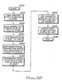
- Figure 30 shows the logical processing of a call transfer through the network.
- Function block 1300 is the entry point for commencement of the processing. Control is passed from the entry to function block 1310 where the host employs the capabilities described above to obtain the reserved telephone number for the phone where the call is to be transferred to.
- function block 1320 the logical terminal id of the terminal that the information associated with the call is to be displayed on is obtained.
- the call is transferred using the standard call transfer capabilities of the switch.
- This capability includes the capability of mapping calls to phones not present in the active switch to facilitate call transfer through networked switches.
- an acknowledgement is sent to the originating switch and forwarded to the host application as shown in function block 1340.
- the host transfers the display information associated with the call to the logical terminal id as shown in function block 1350. Processing is complete so the program is terminated at 1360.
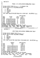
- the first sample scenario is a call from any source to a CMCS agent.
- the originating call comes from a party (P1) to an extension (P2).
- the actions are separated into CBX actions, outgoing call event transaction and host actions.
- CBX Event ! Host P1 come in rings P2
- CALL_ASSIGN P1, P2, First
- P2 answers
- P1 Hangs Up
- CALL_DISCONNECT P1,P2) S(P1,Clean-up(C)) --> Clear
- T(P2) Terminal on which the screen is displayed as determined by lookup of the extension P2 in the phone to terminal (application) table.
- the second call scenario is a pair of successive calls to the same CMCS agent.
- Party1 ( P1 ) is the originator of the call.
- Party2 ( P2 ) is the agent's extension.
- Party3 ( P3 ) is another calling source.
- the third call scenario is a call in which the calling part hangs up before the call is answered.
- Party1 ( P1 ) is the originator of the call.
- Party2 ( P2) is the agent's extension.
- CBX Event ! Host P1 rings P2
- CALL_ASSIGN (P1,P2, First) S(P1,I) --> T(P2)
- P1 Hangs Up
- the fourth call scenario is an example of a call that is transferred.
- Party1 (P1 ) is the originator of the call.
- Party2 (P2 ) is the first party's extension (transferer).
- Party3 (P3 ) is the second party's extension.
- the fifth call scenario is an example of a conference call.
- Party1 (P1 in) is the originator of the call.
- Party2 (P2) is the first party's extension.
- Party3 (P3) is the second party's extension.
- CBX Event ! Host P1 rings P2 CALL_ASSIGN (P1, P2, First) S(P1,I) --> T(P2) P2 answers CALL_CONNECT(P1,P2) P2 flashes PARTY_HOLD(P2,P1) P2 rings P3 CALL_ASSIGN(P2,P3, First) S(P2,I) --> T(P3) P3 answers CALL_CONNECT(P2,P3) P2 flashes PARTY_HOLD(P2,P1) Copy to S(P1, C) --> T(P3) P2 presses PARTY_ADD(P3,P2) Host adds P3 conference to the button conference P2 hangs up PARTY_DROP(P2) S(P1,
- Call parties involved in a connection are identified by the switch to the host processor by sending up call connection events.
- the host recognizes and keeps the state of multiple parties in the conversation in the Call Tracking File discussed above.
- Any party in the conversation may request a copy of the terminal display information and share access to the corresponding application by invoking a CICS transaction by depressing a function key on the terminal display.
- the appropriate information is selected based on a lookup of the requested phone extension, looking up the associated display information, displaying the information on the requesting display terminal, and attaching the phone to the already active conference call.
- the information could also be obtained by indicating the terminal or extension of any of the other parties to the conversation; by indicating the application that any other member to the conversation may currently have access to; or by requesting information using the customer personal identification number of a caller involved in the call.
- one of the parties to the shared call could send information to other parties to the conversation either selectively or in a broadcast fashion through the information contained in the Call Tracking File.
- a caller phones an agent for account inquiry information, and the agent opens a terminal session to collect information on the caller
- other agents can be added to the call through conferencing to handle various requirements of the caller. These parties share the display of information originally created for the caller by the first agent.
- Non-intrusive monitoring This type of monitoring is used by a person who is supervising the agent.
- the supervisor calls the agent during business hours using a CBX feature called silent monitoring and connects to the call to monitor the call unknown to either party.
- the supervisor's display terminal can display the display terminal information that the agent is currently using.
- An agent could also share information with another agent as a call progresses.
- a first agent would press a function key to invoke a CICS transaction signaling the host application to send a copy of the first agent's display terminal to the second agent's terminal.
- Figure 30 is a flowchart showing the logic associated with a caller gaining shared access to a call already in progress.
- Control enters at 6000 and immediately enters function block 6010 which detects a user pressing a function key to indicate sharing is desired. The user is immediately prompted to enter the extension of caller identification associated with the phone call that access is desired as indicated in function block 6020.
- the user entry is formatted into a CICS transaction and sent to the host for processing as indicated in output block 6030.
- the host receives the CICS transaction and moves the display terminal transaction associated with the extension into the user's transaction as shown in 6040.
- This processing involves looking up the extension or customer identification in the CMCS host tables described above to identify the current transaction being displayed. Then, the information associated with the extension is displayed at the user's display terminal as shown in function block 6050 and the CBX connects the user to the extension where the conference is already in progress using standard call conferencing as shown in function block 6060. Finally, the host Call Management Control Table is updated to reflect the new status of the call as indicated in output block 6070 and processing is finished as indicated in terminal block 6080.
Landscapes
- Engineering & Computer Science (AREA)
- Signal Processing (AREA)
- Multimedia (AREA)
- Business, Economics & Management (AREA)
- Marketing (AREA)
- Telephonic Communication Services (AREA)
- Data Exchanges In Wide-Area Networks (AREA)
- Exchange Systems With Centralized Control (AREA)
Abstract
Description
- This invention relates to improvements in data processing applications in a multi-user environment and, more particularly, to a method, involving a digital switch and a host, for conferencing a phone call and Terminal displayed information associated with it.
- The past several years have seen the exploitation of digital switch capabilities, particularly the ability to multiplex voice and data through the switch.
- Traditionally, phone systems were used to manage voice communication. Functions such as connecting, transferring and forwarding phone calls became normal features expected in a phone system. The office environment was incomplete without a phone occupying one corner of an employee's desk. The phone became the umbilical cord linking the employee to their clients.
- Later, computers arrived on the business scene. Applications such as accounts receivable, accounts payable and inventory control mandated the use of a display terminal to communicate information to the computer applications. Soon, the typical office environment included a display terminal to complement the phone for communicating information to the computer.
- Then, as computer applications became more sophisticated and creative, the customer service department recognized the value of the display terminal as a tool and married the telephone with the display terminal to respond to customer requirements. Soon, customer service personnel became accustomed to responding to customer inquiries via a telephone as they entered information into a computer application via a display terminal and exchanged the display terminal information with the customer.
- The display terminal also provided a useful repository of information for the employee. For example, a client could call to obtain a current quotation on a stock portfolio. The client might also request prospectus information on other possible investments. The employee could access a host database to acquire the stock information; and, if the client wanted to place an order for additional stock, the employee could transfer the call to a broker. However, the broker would have to access the same information again that the other employee had before him on the display terminal before transferring the call.
- While the phone and the display terminal provided a wealth of information, the coordination of the phone and display terminal has not been handled effectively in the prior art. An example of a prior art approach to the problem of transferring phone calls is found in U.S. patent number 4,694,483, to Cheung, issued September 15, 1987. The Cheung system provides a telephone call routing system for routing incoming telephone calls to a plurality of agent display modules. The agent display modules have a list of all phone calls that are waiting to be handled by the particular agent. Each of the agent display modules are monitored to balance the calls to each of the displays. However, there is no display information containing customer information coordinated with any of the calls. Therefore, this prior art approach does not provide the unique functionality that the subject invention provides.
- Another prior art approach to data call transfers is found in U.S. patents number 4,535,199 and 4,532,377 to Zink, issued August 13, 1985 and July 30, 1985. The Zink system provides for the redirection of established phone calls to remotely located digital terminals. The system allows the transfer of a voice telephone call to a digital terminal to accommodate the transfer of digital information in response to pressing a DATA button on the phone. The system is employed to accommodate the use of a single phone for transferring data and voice. There is no teaching of display terminal use for the display of data in conjunction with the transfer of a phone call across a network of digital switches. More specifically, there is no teaching of shared access to information associated with a telephone call that is already active.
- Another slightly different approach specifically designed for telemarketing applications is illustrated in US Patent Number 4,788,682 to Vij et al. The Vij patent discloses a method for providing a directory number to a sales person engaged in telemarketing to increase the efficiency of outbound telemarketing personnel. This patent provides no teaching of transferring information associated with a call to another interested party in conjunction with the transfer of the call. Also, there is no teaching of shared access to information associated with a telephone call that is already active.
- This invention is an improvement on US Patent Number 4,805,209 to the same inventors. Features have been added to the original invention to manage the shared access of information associated with a telephone call. We are unaware of any similar capability.
- It is therefore an object of this invention to provide a method of effecting and coordinating the transfer of telephone calls and separate host based information related to a call through a plurality of digital switches to a plurality of individuals under the management of a host processor.
- It is a further object of the invention to provide the option of displaying information associated with a caller on a plurality of display terminals attached to one of the host processors or the digital switches before the call is answered by a transferee responder.
- It is another object of the invention to allow a caller to join a conference call and share access to information associated with the conference call.
- It is yet another object of the invention to allow a caller to join a conference call and share access to information associated with the conference call in an non-obtrusive fashion.
- It is still another object of the invention to use a protocol to simplify communication between the host and the digital switch.
- According to the invention, these objects are accomplished by configuring a set of host data structures to link phone extensions to particular display terminals attached to the host and a particular Customer Information Control System (CICS) application. The data structures also contain information regarding the appropriate transfer of information from the host application to the phone extension across a network of digital switches. Finally, additional data structures are provided to facilitate shared access to voice and data extensions.
- CBX and host have communication managers to facilitate the transfer of messages using a standard protocol. Also, a standard application manager is used to coordinate the activities of the system programs and other preexisting applications. The status of each call is carefully tracked by the system programs and recorded in logs for later analysis.
- The foregoing and other objects, aspects and advantages of the invention will be better understood from the following detailed description of the preferred embodiment of the invention with reference to the accompanying drawings, in which:
- Figure 1 is an illustration of the major functional parts of a Call Management Control System (CMCS) in accordance with the present invention;
- Figure 2 is a system drawing of a prior art Computerized Branch Exchange (CBX) similar to the CBX employed in the present invention;
- Figure 3 is an illustration of the hardware shelf layout of the Central Branch Exchange in accordance with the present invention;
- Figure 4 is an illustration of the Central Branch Exchange Central Processing Unit shelf slots in accordance with the present invention;
- Figure 5 is an illustration of the Central Branch Exchange Time Division Multiplex shelf slots in accordance with the present invention;
- Figure 6 is an illustration of the Central Branch Exchange hardware block diagram in accordance with the present invention;
- Figure 7 is a flowchart of the logic of the Call Management Control System in accordance with the present invention;
- Figure 8 is a continuation of a flowchart of the logic of the Call Management Control System in accordance with the present invention;
- Figure 9 is a further continuation of a flowchart of the logic of the Call Management Control System in accordance with the present invention;
- Figure 10 is a block diagram of the layout of a General Data Stream which is the communication medium in accordance with the present invention;
- Figure 11 is a list of the function and subfunction codes and their meanings in accordance with the present invention;
- Figure 12 is a list of the proper groupings of subfunctions and functions in accordance with the present invention;
- Figure 13 is a list of proper format of the data and time fields and the one byte flag field of the communication transaction in accordance with the present invention;
- Figure 14 is a block diagram and field layout of the CALL_ABANDONED transaction in accordance with the present invention;
- Figure 15 is a block diagram and field layout of the CALL_TRANSFER transaction in accordance with the present invention;
- Figure 16 is a block diagram and field layout of the CALL_CONNECT transaction in accordance with the present invention;
- Figure 17 is a block diagram and field layout of the CALL_GROUP transaction in accordance with the present invention;
- Figure 18 is an illustration of the Call Management Control Table in accordance with the present invention;
- Figure 19 is an illustration of the Extension to Terminal Table in accordance with the present invention;
- Figure 20 is an illustration of the Trunk to Application Table in accordance with the present invention;
- Figure 21 is an illustration of the Dialed Number Indirect Service to Application Table in accordance with the present invention;
- Figure 22 is a state diagram of the call processing in accordance with the present invention;
- Figure 23 is an overview block diagram of the Call Management Control System in accordance with the present invention;
- Figure 24 is a detailed block diagram of the applications that comprise the Call Management Control System in accordance with the present invention;
- Figure 25 is a screen illustration of the View Call Management Control Tracking Table configuration display in accordance with the present invention;
- Figure 26 is a screen illustration of the Extension to Terminal Correlation Table configuration display in accordance with the present invention;
- Figure 27 is a screen illustration of the Trunk ID To Application Correlation Table configuration display in accordance with the present invention;
- Figure 28 is a screen illustration of the Dialed Number Indirect Service Trunk Application Correlation configuration display in accordance with the present invention;
- Figure 29 is a screen illustration of the Agent Extension To Terminal Correlation configuration display in accordance with the present invention; and
- Figure 30 is a flowchart showing the logic of shared information transfer through a network in accordance with the present invention.
- Traditional business telecommunication applications have separate voice and data components. These business applications can be enhanced by integrating the voice and data components as described herein.
- Referring now to the figures, and more particularly to Figure 1, there is an example of the major functional parts of the Call Management Control System (CMCS). The Computerized Branch Exchange (CBX) 1 is the digital switch that manages the telephone processing. The
CBX 1 interfaces to thehost 3 via an Logical Unit (LU) 6.2interface 2. Using the example discussed above, to transfer the phone call fromextension 4 toextension 6, the agent performs the normal tasks associated with transferring a call. TheCBX 1 translates the request into a corresponding host display terminal transfer request transaction fromterminal display 5 to displayterminal 7. The transaction is built and sent from theCBX 1 through the LU 6.2link 2 to thehost 3. Thehost 3 performs a table lookup to determine theterminal display 7 associated with thenew phone extension 6. Then, the current display transaction that is displayed on the transferrorterminal display 5 is displayed on the newterminal display 7. A more detailed analysis of the processing is disclosed below. - An example of a prior art CBX, similar to the preferred embodiment, is provided in Figure 2, which illustrates the computer control equipment associated with the prior art
ROLM CBX II 9000. The hardware consists ofredundant memory 10, a shared, switched I/O bus (ISB) 20,various interface cards 30, disk 40, andredundant processors 50. A remote node attachment is also provided via the Inter Node Link (INL). A more complete discussion of the hardware environment is provided in theROLM CBX II 9000 Business Communications System, published by ROLM Corporation (1986). CBX hardware for practicing the subject invention is shown in Figures 3, 4, 5, and 6. Figure 3 illustrates the hardware shelf layout of the CBX. Shelf one 51 is a common control shelf in a redundant system cabinet or another Time Division Multiplex (TDM) card shelf in a nonredundant system cabinet. Shelf two 52 is always a common control shelf. Shelves three 53 and four 54 are always TDM card shelves. Air cooling systems and redundant power systems are provided at 55 to dissipate heat and provide system power. - Figure 4 illustrates the CPU shelf slots of the
common control slot 52. As shown, there are memory-cards 60, processor set 61, shared input/ output (I/O)hardware 62, anddisk drive units 63. The processor cards contain the microprocessors. Additionally, there is acommon control motherboard 64 that joins thememory cards 60, the processor set 61 and the shared I/O hardware 62 to the system bus. Thecommon control motherboard 64 is used to join the other common control motherboard from the redundantcommon control shelf 51 and theTDM shelves - Figure 5 shows the TDM shelf slots. The TDM communication cards fit into the slots shown at 65. The other TDM cards occupy the slots at 68.
Slot 70 is reserved for Line Shelf Monitor LSM which monitors the power supply and contains the fuses. If LSM detects a power supply failures or fuse failures, it is reported to error analysis by a scanner reporting a monitor error. Error analysis then parses specific decision trees to generate suggested actions. - The following hardware description discusses Figure 6, which is a hardware block diagram of the CBX system. The figure is a functional representation of the preferred embodiment of the CBX.
- Nodes are the modular building blocks of the CBX system. Each node can function as a stand-alone telecommunication system consisting of the time division multiplexing (TDM) switching network, processors, cabinet and power system, and interface cards. A single-node system can expand from one to five equipment cabinets to accommodate up to 2,000 lines.
- The CBX is a digital switching system using TDM and pulse code modulation (PCM) to support a wide range, of voice, data, and specialty applications. A 32-bit processor and Random Access Memory (RAM) provide control intelligence within each node.
- Multiplexing is a method of using a single communication channel to carry multiple speech and/or data transmissions simultaneously. The TDM channel use is alternated between users or between system functions, each receiving a small portion of channel time (a time slot) in rotation. The channel seems to be reserved for each individual transmission, but because of the highspeed channel, it carries many transmissions simultaneously.
- When the first CBX was shipped in 1975, ROLM was the first vendor in the industry to use PCM technology. PCM is the process which analog sound waves of voice conversations are sampled, translated into digital signals, transported over the TDM network, and reconstructed into analog signals. The CBX samples voice signals at 8,000 times per second. The samples are converted into 8-bit binary words, which are transmitted over the data bus.
- The following describes the major components of a single-node communication system.
- Broadly defined, Bus is the entire TDM switching network. It maintains the connections established by the processor and passes information between the common control electronics and the telephones, terminals, and trunks. The bus is the vehicle for intranode communication.
- The bus is a 16-bit, parallel, unidirectional bus that has a capacity of 295 megabits per second (Mbps). It provides 1,152 two-way or full-duplex communication channels, of which 1045 are available for voice/data traffic. The system uses the remaining channels for various control functions, such as setting up phone displays.
- The major components of intranode communication are the TDM Network Control Group. This group consists of the:
*Intrashelf Bus 84
*Intershelf bus 86 & 87
*Expander 80 cards
* TDM controller cards - On the back of each TDM shelf is an
Intrashelf Bus 84 implemented on the TDM backplane. TheIntrashelf Bus 84 permits communication within a shelf. On each TDM shelf, oneExpander 80 card plugs into eachIntrashelf Bus 84.Expander 80 cards provide the interface between theIntrashelf Bus 84 and the Intershelf Bus (ISB). - The total bandwidth available on the
Intrashelf Bus 84 is seventy-four Mbps. EachIntrashelf Bus 84 includes a 16-bit bidirectional data bus, a 10-bit address bus, and an "enable" line to each card. The enable line eliminates the need for configuring each card with a particular shelf address, so that interface cards can occupy any slot on the shelf. In addition, the enable line simplifies address decoding, which increases reliability - ISB is an integral part of the proprietary Bus structure, handles communication among shelves through a flat, ribbon cable attached to the TDM controller (TC 81) card and the
Expander 80 cards on each shelf. - The ISB supports a data rate of 295 Mbps over two unidirectional buses: the
source bus 87 and theDestination bus 86. - If a system has redundant processors, the
Expander 80 cards are also redundant. When one common control side of the cabinet is active, one of theExpander 80 cards is in use, while the redundant (inactive) common control side andother Expander 80 card will wait to become active. - Each
Expander 80 card contains a connection table for all voice and data connections affecting its shelf. This frees intrashelf bandwidth for call data, instead of consuming bandwidth for the address information needed to make connections. - The
Expander 80 cards,TC 81 card, andTurnaround 82 card use the Bus ISB clock (located on theTurnaround 82 card) for timing the Bus traffic. This maintains the correct timing relationship between the data, which travels along the bus, and the clock pulses. The turnaround card also sends out a pulse at the beginning of each sampling interval. The pulse tells theExpander 80 card to start again with the first entry in the connection table. - The
Bus TC 81 card, maintains supervision of the processor-ISB-interface communication.TC 81 cards reside on the common control shelves incabinet 1 of a CBX node. TheTC 81 card is responsible for the following three activities: loading and verifying the connection table on eachExpander 80; configuring the turnaround card and InterNode Link (INL 83) hardware; and communicating with the various line card groups. TheTC 81 card handles up to 12 Mbps of control information. - The
TC 81 card signals its activities by using a bus control field. Control packets contain addressing, control, and data information for loading theExpander 80 connection tables and reading the status of line cards. - The
TC 81 cards maintain a communication path between the two ends of a voice or data call. The processor, through theTC 81 card, switches digitized signals by assigning them to unique time slots on the ISB. The Bud ISB uses TDM techniques, which enable the ISB to carry a large amount of simultaneous voice and data transmission. - As its name implies, the
Turnaround 82 card turns the data around on the bus. TheExpander 80 card on the transmitting card's shelf places a data word on thesource bus 87. The data word travels to the right until it encounters theTurnaround 82 card, which receives the word and retransmits it ("turns it around") to theDestination bus 86. Then theExpander 80 on the destination shelf captures the word and sends it on to the proper card. - The advantage of using the turnaround card is that information retransmitted in an individual time slot to the
Destination bus 86 and the receiving card can be completely different from information received in that time slot from thesource bus 87 and the transmitting card. This doubles the traffic capacity of the switch by allowing two internode conversations to take place in a single time slot on the bus. - To further understand how this occurs, imagine that a conversation is taking place on telephones with connections in node A. The system transmits a voice sample on the node-
A source bus 87, and the sample encounters theTurnaround 82 card, which places this sample on the destination part of the same bus. The time slot on the destination part of the node-A bus has now become free. - The
Turnaround 82 card can fill this empty slot with a voice sample from the other end of the conversation. In this way, the signals from both ends of the conversation can occupy the same time slot simultaneously. - In each node of a multinode CBX system, the system clock provides timing for the TDM network via the
Turnaround 82 card. It also synchronizesINL 83 operation between nodes. The source of this clock can be its own internal system, or it can synchronize from an external T1 interface trunk. The system clock conforms toStratum 4 of the Bell Network Synchronization Plan. - The new Bus provides the CBX with 2,304 timeslots per node. Bandwidth is the measure of voice and data traffic capacity in the CBX. The clock speed of the Bus 16-bit parallels backplane is 18,432 MHz. The total bandwidth of the system is, therefore, 18,432 megahertz/
second x 16 bits/cycle = 294.912 Mbps. - To restate this in terms of communication channels: since the CBX sampling frequency is 8 kHz, the bandwidth in each direction of a communication channel of the 16-bit backplane is
8,000 samples/second x 16 bits/sample= 128,000 bps (128 Kbps). - Note: Each sample is actually 8 bits; however, 16 bits are used to allow for future expansion of function. Therefore, the total bandwidth in a node with Bus is 1,152 channels x 128 Kbps x 2 connections/full-duplex channel = 294,912 Mbps in each node. Thus, the total bandwidth for a 15-node system with bus is
15 nodes x 295 Mbps/node = 4.425 Gbps (or 4,425,000,000 bps). - The CBX offers the advantage of computer common control. With the stored programs of computer common control, it is easy to update features as business needs change. This provides greater flexibility and reduces the cost of feature additions and other changes that may be made in the future.
- The computer common control group directs all activities within the CBX system. A single-node CBX supports 1 or 2 common control shelves.
Shelf 2 ofcabinet 1 always houses a computer common control group. To increase reliability in critical applications or larger systems,shelf 1 can accommodate a second, or redundant, common control group. These groups consist of:
* Processor
* Memory
* Enhanced Communications Processor
* Disk systems
* System Monitor card
* I/O card - The 9000 is a 32-bit processor employed by the CBX. It is a ROLM-proprietary design using powerful, high-speed, bit-slice technology, with a ROLM proprietary instruction set. A single node configuration supports from 7,500 to 11,000 Busy Hour Call Attempts (BHCA); that is, the total number of call setups attempted during the hour when the CBX carries the most traffic. In a redundant system, the processor controlling the system is the active processor; the other one is the standby processor. Either processor can provide standby common control to prevent a failure in the active common control from halting system operation. The active processor continually transfers new information, such as moves and changes, Station Speed Calling information, as well as calls-in-progress information to the standby computer. Therefore, in the event of a switchover from the active computer, the standby computer always contains current information regarding the state of the system.
- Every 24 hours, there is a systematic switchover from the active processor to the inactive processor (usually late at night) to ensure operational readiness of the standby processor. This redundancy results in virtually uninterruptable system operation.
- CBX uses RAM to store all system software. Stored in memory are the system operating software, system-specific configuration parameters, and operating data. Each processor can access up to four memory cards. Each memory card accommodates 1 million words of memory, with each word composed of 16 bits plus 6 Error Correcting Code (ECC) bits. ECC improves the accuracy with which the system memory retains information. By automatically detecting and correcting all memory single-bit errors and detecting most multiple-bit errors, ECC minimizes the likelihood of a system failure due to a malfunctioning memory component.
- Systems with redundant processors are capable of detecting multiple-bit errors and automatically switching to the redundant computer. In addition, a hardware register on the memory card enters errors into a table to aid servicing.
- The major advantage of ECC is the elimination of "soft errors" that can generate numerous service calls. Soft errors are intermittent malfunctions, usually of short duration and low frequency, that might result from the execution of specific data patterns, the temperature of the room or static electricity. Soft errors can cause erratic system behavior, forcing service personnel to spend hours troubleshooting a fault that may not exist. The error detection and correction capability improves the reliability of the CBX system and eliminates needless hours of "trial and error" troubleshooting
- The Enhanced Communications Processor (ECP) is a two-card processor that provides improved call setup, a foundation for future data products and applications. Supporting the ECP are the Data Front End (DFE) cards which reside on TDM shelves, and offloads the data call setup messages from the CBX processor. The DFE also allows call setup to occur at the baud rate of the calling device. This facilitates the use of popular PC-based communication packages that permit automatic data call setup.
- Peripherals housed on
shelf 2 consist of two 3.5-inch, 1.44M floppy disks and one 5.25-inch, 40M hard disk, and a peripheral device controller (PDC) card. The right-hand end of the shelf contains the disk assemblies. IBM provides the CBX System Software, Release 9004.3, and diagnostic programs on floppy disks. The floppy disk system stores Initial Program Load (IPL) software, a back-up copy of the current site data base, and software updates (new software releases). - IPL is a "cold start" that loads information from a floppy disk into the system's main memory and is then written onto the 40M hard disk assembly. IBM technicians perform IPL at a customer's site when they install a system. The hard disk system contains disk storage media that are sealed from the environment to provide a high degree of reliability. The hard disk contains the operating system program. It also has sufficient storage for certain voice and data applications to store information on a real-time basis. For example, the hard disk stores configuration tables, Moves, Adds, and Changes (MAC), and Forced Authorization Codes (FAC). Use of a hard disk provides faster access for configuration and move-and-change support that are available from floppy disks.
- Automatic Program Load (APL) software monitors the operating system program. After a power outage exceeding 20 minutes on ac systems (the maximum time the emergency battery will maintain memory until power is restored), APL reloads the system program automatically from the hard disk. Prior to that, memory is stored in RAM. APL for dc systems is necessary only if the system loses operational battery power ( a rare occurrence)
- Diagnostic cards (the System Monitor Card _SMC_ and Redundant Shelf Monitor _RSM_ are housed on the common control shelves.
- SMC provides fuse/circuit alarm detection, software alarm detection, temperature alarm detection, power-failure detection, and dc voltage monitoring. This printed circuit card resides in one slot of the common control shelf (shelf 2) in both redundant and nonredundant configurations.
- Power-failure indicator LED's located on the SMC, light when voltage drops. LED's also provide a high-temperature warning. Fuse-alarm circuitry generates both visual and audible alarms should a fuse malfunction.
- RSM provides redundant common control shelf status for SMC. One RSM resides on the redundant processor shelf (shelf 1) in
Models - One Local Shelf Monitor (LSM) resides on each TDM or
INL 83 shelf. LSM's monitor TDM shelf power and temperature status and notify the SMC of problems. - The SMP is a 4-channel maintenance interface that resides on
common control shelf 2. Two of the four ports on the SMP are permanently assigned to the system terminal and the system modem. - The two available ports can support:
* Automatic Call Distribution terminals
* System administration data link
* Call Detail Recording list device - Located on
shelf 2 in the switched I/O bus, the Quad Serial I/O card is an optional card used to increase the number of devices a system can support. Each Quad Serial I/O card supports up to four devices used for features such as Expanded Traffic Reports, Automatic Call Distribution (ACD) statistics, moves, and changes. The Quad Serial I/O card supports the following RS-232-C ASCII devices, which run at data rates of up to 9.6 Kbps:
* Modems
* Printers or output-only devices
* Loaders or input-only devices
* "Smart" and "nonintelligent" terminals
* Automatic Call Distribution terminals
* Interface to the Phonemail Application Processor - A node consists of one to five connected equipment cabinets. The maximum single-node configuration has 5 cabinets and a total of 20 shelves. When viewed from the front,
cabinet 1 is on the left withshelves 1 to 4.Cabinet 2 is next withshelves 5 to 8, whilecabinet 5 is on the far right withshelves 17 to 20. - Shelves contain three categories of equipment: computer common control; TDM interface cards for line, data, or trunk interface; and
INL 83 for internode communication of voice and data information. - A more detailed discussion of the preferred mode of operation is provided in the ROLM System Service Manual, ROLM Corporation, October 1987.
- The CBX is modified to accommodate the CMCS application as follows:
- 1) Whenever a trunk or extension is ringing a phone with the CMCS monitor flag set on, a message is sent out of the host interface link. After encountering a CMCS flagged extension, the subsequent call events associated with the call continue to generate CMCS event transaction messages which are sent to the host. The message contains the trunk number (or extension) and the ringing extension number.
- 2) Whenever an answering party (attendant or extension) transfers the trunk (or extension) to another extension, a message is generated. The message contains the trunk number and the ringing extension. The extension of the transferror is included when the transfer is screened (the transferror stays on and notifies the called extension of the call). If the transfer is not completed and the transferror retains the call, notification is sent that the call did not complete.
- 3) If a trunk or extension is subsequently connected to another trunk, then a connection message is sent out of the host interface link. The message contains the originating source identification and the terminating trunk numbers.
- 4) CBX system software connection messages are sent when ACD calls connect to phonemail for callback messaging or call redirection.
- 5) Whenever a caller from a trunk or extension queues for an ACD group id/pilot number configured for CMCS, a connection message for the queue is sent out the host interface link. The message contains the originating trunk or extension and the ACD group id/pilot number.
- 6) Finally, whenever a CMCS call is terminated, a message of termination is sent identifying the originating trunk or extension to the host.
- The host link is a standard System Data Link Control (SDLC) communication link that conforms to the LU 6.2 standard. A detailed description of an LU 6.2 communication link and how to implement a program interface to conform with this standard is provided in the following publications by International Business Machines Corporation: Systems Network Architecture: Sessions Between Logical Units, GC20-1868; SNA Transaction Programmer's Reference Manual For LU Type 6.2, GC30-3084.
- The host hardware is one of the IBM System/370 processors. A detailed analysis of the IBM System/370 processor is provided in S/370 Reference Summary, GX20-1850, published by International Business Machines Corporation. While a S/370 host processor is described in the preferred embodiment, those skilled in the art will recognize that the invention can be practiced on other mainframes, minicomputers and microprocessors.
- There is a separate CMCS application that resides in the CBX software application memory. The application is invoked by the initiation of any call to a phone that is flagged in the CBX for CMCS event processing. The CBX software is responsible for processing information from each flagged extension, managing an SDLC communication link to the host, formatting LU 6.2 transactions and sending the formatted transactions via the SDLC card to the host processor.
- Routing of a phone call is based on standard algorithms in the CBX for the originating call and the final destination of the call. Once the proper routing is determined, a host transaction is formatted and routed through the SDLC card to the host. The format of the various transactions are shown below in the message processing portion of the detailed invention. For more information on the detailed processing of calls, the reader is referred to the ROLM 9004.3 Business Communication System.
- A discussion of the host software is appropriate to understand the functions of CMCS. Figure 23 provides a software overview of the CMCS system. The operating system, which manages the other host software and their use of system peripherals, is MVS/
XA 2000. The host communication manager, ACF/VTAM 2002, interfaces with the operating system and manages the communication between the host and other peripherals such as theCBX 2004. CICS/VS 2006 manages the flow of information from application to display terminals. - The CMCS applications 2010 process the transactions from the
CBX 2004 and coordinate the transfer ofapplication 2014 information to theterminals 2015. The CMCS 2010 anduser 2014 applications are all CICS application programs. The interface to the user applications from CMCS 2010 is the Application Programming Interface (API) 2018. - Systems Operations manages the CMCS 2010 system through the operations interface (OI) 2016 and an attached
CMCS console 2012. TheCMCS console 2012 allows support personnel to track system operation and run queries against the three system files. The system tables and logs are:configuration 2024, log 2022 and management information services (MIS) 2020. The system tables are discussed in detail below. - A variety of operating systems can be employed interchangeably for the host processor. The preferred operat ing system is Multiple Virtual Systems /
Extended Architecture 2000 which is a multiple task, multiple user environment for execution on the newest of IBM's S/370 processors. The details of the operating system are described in MVS/XA OLTEP LOGIC, SY28-1188 and MVS/XA Logic VOLUMES 1-17, published by International Business Machines. There are two other operating system environments that the preferred embodiment may execute in. They are Virtual Machine/System Program and Virtual System Extended/System Program. These two operating systems are similar to MVS/XA and are described in VSE System IPO/Extended General Information Manual, GC20-1889, and VM/SP IPO/E General Information Manual, published by International Business Machines Corporation. - ACF/
VTAM 2002 is the communication monitor that executes under the control of the operating system and controls the communication link to the CBX and each terminal that is attached to the host. VTAM controls the Systems Network Architecture (SNA) environment that supports the LU 6.2 protocol. A detailed description of VTAM is provided in the following references all published by International Business Machines Corporation: VTAM NCP SNA SNI NLDM SSP NCCF, SC27-0659; IMS LU 6.1 Adapter for LU 6.2 Applications, SH20-9254; Systems Network Architecture: Sessions Between Logical Units, GC20-1868; SNA Transaction Programmer's Reference Manual For LU Type 6.2, GC30-3084. - This last manual presents detailed information on the functions that the SNA LU 6.2 2008 protocol provides to application programs. The manual is written for individuals that design application programs for use on an implementation of SNA LU type 6.2. It does not describe any specific IBM product; it is intended to be used with IBM products such as CICS/VS, VTAM and MVS/XA.
-
CICS 2006 is a general purpose data communication monitor that reduces the effort necessary to implement terminal-oriented transaction applications. CICS is used around the world to enable applications, ranging from payroll to inventory control, to interactively handle a large number of displays. - A description of the operation of this system can be found in the Customer Information Control System/Virtual Storage (CICS/VS) General Information Manual, GC33-0155-1 published by International Business Machines Corporation. A more detailed description of the logic of CICS is provided in CICS/OS/
VS Version 1Release 7 Modification 0 (MVS/XA Feature) Listings, LYA4-3018; and CICS/VS, LIC Prog 5740-xx1, Logic, LY33-6034; published by International Business Machines Corporation. - The CMCS applications 2010 and the
User applications 2014 are all implemented as CICS application programs. Theuser applications 2014 interface to CMCS through the Application Programming Interface (API) 2018. An application program can acquire status information and access the CMCS logs 2020, 2022 & 2024 through the API. This information can be used to coordinate the display of information from application programs in addition to the information displayed by the CMCS system. - A functional description of the CMCS processing is provided to illustrate the system operation. For purposes of this description, the following terms are used:
- Initial Screen is the first screen that the CMCS agent gets when a call is processed. Once the CMCS agent enters the customer identification, such as an account number or a name, the screen becomes a customer information display.
- Customer Information Screen is the screen that a CMCS agent gets if the call has already been screened by another employee.
- Normal Extension is an extension that has a physical appearance to a phone, as contrasted with ACD pilots or Phonemail pilots.
- Extension is considered the extension normally associated with a phone (normal extension) unless a qualifier appears before extension.
- CMCS caller is a trunk or extension that calls a CMCS called party.
- CMCS called party is an extension, an ACD agent, an ACD group, an ATC, or trunk which generates CMCS telephony activity events.
- CMCS agent refers to the operator, phone and host display terminal associated with a particular agent.
- Telephone activity is any call activity that occurs on a CMCS called party extension, for example: ring a CMCS called party or queue for an ACD group tagged as a CMCS called party. Flagged CMCS called party is a CMCS called party which has the ability to turn CMCS event generation on for all subsequent telephony activity.
- "First Time" CMCS event is the first CMCS event with special initial call flag set in the event that is sent when a CMCS caller has telephony activity with any flagged CMCS called party for the first time.
- To limit the volume of events that are sent from the CBX and to identify callers that have dealt with CMCS sometime during the call, target extensions are tagged as CMCS. A target extension is equivalent to a CMCS called party. If a caller has telephony activity with a CMCS called party, then the caller is tagged as a CMCS caller. This is a dynamic tag and remains active until the CMCS caller becomes idle.
- Events are sent from the CBX to the host for telephony activities associated with a CMCS caller and CMCS target. Examples of the processing and transactions associated with the events are provided in the sample scenarios. Note that once a caller is tagged as a CMCS caller, events are sent for all subsequent telephony activity until the call is finished. CMCS callers can be trunks or normal extensions exclusively. CMCS called parties can be ACD group pilots, normal extensions, ATCs, and trunks.
- Only one display terminal is associated with the activity of an individual extension. For example, suppose that an extension has multiple appearances on two phones. Then, any telephony activity on those two phones with that extension affect the display of information on the display terminal.
- A CMCS called party that is being rung by a CMCS caller is presented with the initial customer screen or the customer information display terminal screen that the previous CMCS called party was viewing. Also, as a CMCS caller transfers forward to other CMCS called parties, the display terminal of each successive CMCS called party is updated with either the initial screen or the customer information screen.
- A blind transfer is a special type of transfer which transfers the display terminal screen that the CMCS called party (transferrer) was viewing to the transferred CMCS party while the call is ringing. This allows the agent some additional preparation time before answering the call.
- The host is updated each time the status of a CMCS caller and CMCS called party changes. A status change occurs when a call follows busy, DND or station forwarding. The host also knows when a CMCS caller places a CMCS extension on hold. The host processing is handled by CICS application programs that are individually discussed below. Figure 23 is an overview block diagram of the CMCS application environment as they relate to the present invention.
- The call tracking application program includes the LU 6.2 communication manager. The primary function of call tracking is to maintain the call status on the event stream and resolve any ambiguities before reporting events to other applications. If call tracking determines that a transaction associated with an originating source identification (extension) needs updating, it refers the event to the Screen Update program. Queued events and events regarding source identification which contributed to a queue count are passed to ACD load balancing.
- Screen update application program performs screen transfer, initialization and recovery for each call. The processing is triggered by events on the CMCS host control link which the call tracking program passes to it.
- CMCS MIS program receives the CMCS table entries maintained for each call tracking every change of state, data entry field and queue count. The CMCS MIS program puts these records into a
circular buffer 2020 of Figure 23 to store the information for other applications to process. - This program processes the CMCS table entries to allow a CMCS operator to interrogate error conditions and monitor events on CBX source and target identifications (extensions). This program also configures the CMCS system and maintains the
configuration file 2024 of Figure 23. - CMCS customer applications are any CICS application programs. For purposes of our discussion, we will discuss a single CMCS customer application program that maintain a database of customer information for CMCS agents. In reality, there are many CICS applications currently used for such diverse applications as accounts payable, accounts receivable, inventory control, stock queries and order entry. By providing an interface to existing applications, CMCS coordinates the display of information on a display terminal with the transfer of phone calls without changing existing CICS applications.
- Referring to Figure 7, a flowchart is shown that provides the logic of the CMCS system. The processing begins at
function block 500 where the CBX responds to the incoming call. This function block refers to normal CBX call processing as detailed in ROLM publication, ROLM CBX II 9004.3, published by International Business Machines Corporation. - Then, in
function block 510 the CBX accepts the network dialing that accompanies the call and determines the correct extension to connect to. This is also normal call processing as described above. However, infunction block 520, the CBX generates a call event transaction and sends it via the LU 6.2 link to the host as detailed in the Message Formats section of the Logic Description. - The host Call Tracking Application, one of the CMCS applications 2010 of Figure 23, receives the call event, parses the information and determines if this is the first event for the extension. If it is the first event, then a call event record is created in the Call Management Control Table (CMCT), shown in Figure 18. The call event record is updated to reflect each event that affects the extension. Then, the initial screen to be displayed is determined using the incoming trunk and/or the target phone extension as shown in
function block 530. - The Call Tracking Application uses the phone extensions sent from the CBX to access an extension to terminal (logical unit address (LUA)) table and determine the correct display terminal to send the screen display to. The extension to terminal (LUA) table is shown in Figure 19.
- The network used in this example contains terminal displays and phone extensions from countries around the world. The only information necessary to make the connections to the various extensions and send the display information to the correct display terminal is contained in the extension to terminal (LUA) table.
- The extension to terminal (LUA) table is searched based on the sixteen byte extension of the called party to obtain the terminal LUA associated with the phone call. When a match is found between the sixteen byte extension and the first sixteen bytes of a record, the next twenty-four bytes of the record is the LUA of the associated display terminal. The host application then knows which display terminal to send the screen information to.
- The CMCS Customer Application sends the initial terminal display to the display terminal, as shown in
function block 540. The display terminal LUA is determined by the Call Tracking Program by searching the extension to terminal (LUA) table and acquiring the correct LUA for the associated display terminal as discussed above in reference to functionblock 530. - The agent who receives the call and the information on the display terminal has the option of entering additional information on the display terminal to further enhance the customer information as shown in
function block 550. If the caller requests additional services that require the help of another agent, then the agent can transfer the caller using the standard call transfer features of the phone as shown infunction block 560. - A test is performed at decision block 570 to determine if another agent is available in the group that is being transferred to. If an agent is not available, then control is transferred to a queue for callers that is discussed in more detail later. If an agent is available, the CBX connects the caller to the other agent and sends a call event transaction through the LU 6.2 link to the host as shown in
function block 580. The transaction contains the same source identification as the previous transaction, but now it also contains the phone extension of the agent that the call is transferred to. - The host, in
function block 590 of Figure 8, receives the call event from the CBX and identifies the caller by the same source identification and matches the new target extension to the terminal LUA as discussed above by a table lookup. Then, the host CMCS screen transfer program transfers the terminal transaction associated with the previous terminal to the new terminal LUA as shown in function block 600. As a result, the terminal associated with the caller shows the customer data as the phone is ringing as shown in function block 610. This would allow the agent to assimilate the information on the terminal display and prepare for the caller as shown infunction block 620. Optionally, the terminal display could be updated as soon as the phone call is answered. - The agent is now fully prepared to deal with the customer without having to ask the customer for information that has already been conveyed to the first agent. The new agent can acquire additional pertinent information and enter it into the CMCS Customer Application as shown at 630.
- The application program interface, 2018 of Figure 23, allows a customer's existing CICS application program to do optional intermediate processing during the display terminal transfer if a different display should be displayed other than the screen that was currently used at the prior display terminal.
- A test is performed next at decision block 640 to determine if the caller needs to talk to another agent. If the caller needs to talk to another agent, control is passed to function block 560 of Figure 7 to process the call. If the caller does not need additional assistance, then the caller hangs up the phone, as shown in function block 650, and the CBX notifies the host that the call is completed by sending a CALL_DISCONNECT transaction to the host as shown in Figure 13. Then, the host application CMCS Call Tracking Program cleans up the host record of the call and stores the user data collected.
- The existing CBX queuing capability is used by the CMCS system as shown in Figure 9. When a call is transferred and the party is not available, then the call is queued as shown in function block 670, and the caller listens to music on hold until the agent is available. Also, a call event transaction is sent to the host to let the host know that the previous extension is free and that the caller is now in a hold or waiting condition as indicated in
function block 680 and updates the CMCT. This capability helps the host place the terminal display associated with the caller on hold and coordinate terminal display processing with the CBX. - A test is performed in
decision block 690 to determine if the agent is available. If the agent is available, then control is passed to function block 580 of Figure 7 to process the connection of the call and the display terminal update. If the agent is still not available, a test is performed atdecision block 700 to determine if the caller has hung up. If the caller has not hung up, then control is passed to function block 670 to continue the hold pattern. If the caller has hung up then the CBX notifies the host of the event with a transaction as shown infunction block 710 and the host cleans up the call environment, by updating the CMCT, as shown infunction block 720. - Figure 24 provides a detailed block diagram of the CMCS application programs and the communications between the applications.
- The
call tracking application 2032 of Figure 24 is comprised of subroutines for carrying out discrete functions. The first is the initialization subroutine which reads user defined configuration defaults such as the CBX ID/LU associations, the CBX access codes, error handling parameters, queue parameters and API interface parameters and determines the correct CICS transaction program application to execute to provide the screen for the display terminal associated with the phone extension. - The second subroutine is the
communication manager module 2030 of Figure 24 which is responsible for managing communication between the CBXs and the host using LU 6.2 protocol. Thecommunication manager 2030 receives call event transactions from the CBX, sends request action messages to the CBXs, and sends/receives initialization messages with version numbers and diagnostic messages that notify the host of any changes in the CBX status. Thecommunication manager 2030 processes the messages and writes information records to a CICS temporary storage queue to facilitate access by the othercall tracking subroutines 2032. - After the
communication manager 2030 receives the messages, they are read from the temporary storage queue and evaluated by the preliminary routing/error handling section of call tracking 2032 to separate error records from event transaction records. - Event transaction records that have sub function codes of call assigned or call queued are evaluated by the validation/building section of call tracking. The originating source identification is validated for "first time" calls because the same source identification is used for the duration of the call. The target identification is validated for each transaction received in call tracking because it could change during the call.
- The originating source identification is required to be a CMCS trunk or an extension. To determine the initial screen display, the trunk and extension tables must be searched. The initial screen display is performed by searching the trunk to application table, the Dialed Number Indirect Service (DNIS) to application table and the extension to application table. Depending upon the match found, the appropriate CICS initial transaction identification will be used.
- The search logic that is executed is presented below in pseudo-code form:NOTE: A detailed discussion of the CMCS system tables is provided later in the detailed logic.

- A similar procedure is used for queued calls. If the queued call is a "first time" queued call, then the call is validated as discussed above. However, if it is not the first time the call generated an event, then there is no need to validate.
- A major function of the call tracking application is to track the status of CMCS calls. The call management control table is used to store status information on CMCS calls. Calls remain in the Call Management Control Table (CMCT) as they are assigned and queued. They are not removed from the CMCT until a disconnect transaction is received from the CBX.
- After the event record has been validated and the record containing host applications and terminal LUA has been built, the call tracking application performs CMCT validation before placing built event records in the CMCT or removing a call from the CMCT. Each time the CMCT is updated, a copy of the table entry is sent to the MIS interface.
- The logic of the CMCT validation check is presented below:
- For event records which have a "first time" call indicated, there should be no entry in the CMCT for the originating source identification. If there is, the entry is written to the error log, deleted from the CMCT, and the new record is placed in the CMCT. Also, the queued flag for the entry must be checked before removal. If the flag is set, then the Queue Table Queue Count for the target extension is decremented.
- Non-"First Time" Call Records Records which do not have the "first time" call flag indicated should already exist in the CMCT. The CMCT is searched on originating source identification to obtain the information associated with the call. If no match is found an error situation is written to the error log and the new information written to the CMCT by the update code.
- After records pass the validation checks, the built record is evaluated to determine of the record is added, deleted, updated or unchanged in CMCT.
-
- An addition of a record to the CMCT is performed if the record is queued or assigned and not in the CMCT. If a record is flagged as "first time" and Assigned, then the ASSIGNED flag is set and the QUEUED flag is cleared. If a record is flagged as "first time" and queued, then the ASSIGNED flag is cleared and the QUEUED is set. If a record is not "first time" and ASSIGNED, then the ASSIGNED flag is set and the QUEUED flag is cleared. If a record is not "first time" and queued, then QUEUED is set and the ASSIGNED is cleared.
- Updates occur each time that a call status changes to reflect the new condition. The current terminal identification changes each time a phone call is transferred to reflect the current terminal associated with the phone extension. The assigned and queued flags are changed to reflect current status as described above.
- Notification of the Screen Presentation Application Screen presentation is notified when any of the following events occur:
- 1) a call is received with "first time" indicated;
- 2) a call is queued;
- 3) a call is assigned; and
- 4) a call is disconnected.
- Depending on the previous and current changes to the CMCT entry, the CMCS call tracking application passes action required parameters to the screen presentation application. These parameters include the following:
START: issued for "first time" calls that are assigned or when a call that was queued for the first time becomes assigned.
SAVE: issued when a call which was assigned is now queued. For example, when a call is transferred and put in queue on hold.
RESTORE: issued when a call that was queued (and not a "first time" call) becomes assigned.
TRANSFER: issued when a call that is currently assigned to an extension becomes assigned to another extension.
CLEAN-UP: issued when calls in CMCT are removed. - The MIS application is notified whenever there are changes made to the CMCT. The information is written to a circular file for batch processing.
- The screen update application, 2034 of Figure 24, provides the function described in function blocks 610, 620 and 630. Transfers of information from one display terminal to another are performed by updating the VTAM addressing so that the new display terminal is identical to the information on the display terminal that the agent that transferred the call was viewing. This is accomplished by substituting the LAU of the transferred to terminal display with the LAU of the transferring display and logically transferring the display terminals. An option provides for passing the update request to the user application for processing before transferring.
- The CMCT is used to track the status of calls in progress and provides control functions for a call. Figure 18 shows the CMCT and each of the fields that make up the individual records. Information concerning a phone call is initially obtained from the other tables to fill out the fields of a call record. This record is then written to the CMCT and used to record the status of the call until it is terminated.
- The
Sub-func code 1100 is a coded one-byte integer value. The codes and the functions associated with each code are shown in Figure 12. - The Originating Source ID 1102 is the key that uniquely identifies the source of the call being tracked by CMCS. The ID can be a TRUNK ID or and EXTENSION ID. The Originating Source ID 1102 is kept for the duration of the phone call.
- The Originating Source ID 1102 is used by the host to "track" calls in the CMCT. All messages that are tracked by the host must have an Originating Source ID 1102.
- The Target ID 1104 is the termination point of the CMCS call. It can be an EXTENSION ID or a TRUNK ID. The Target ID 1104 can change during the phone call. Changes typically occur when a call is transferred. It is used to track the termination point of calls in the CMCT.
- The Term ID 1106 is the unique four bytes of character identification for the 3270 terminal that is currently associated with a call. The 3270 terminal could be a personal computer or other 3270 emulated terminal.
- When a call is transferred, the TERM Id 1106 that is currently associated with that call is written to the CMCT by the call tracking application. It is also used by the screen presentation application to determine where to obtain information from.
- The
Ctl # 1108 is a fifteen byte key that is used by the CICS applications to identify any call being managed by CMCS. This key can be used to obtain status information from the various logs that CMCS manages. - The Initial CICS Trans Id 1110 is a four byte code which is used by CICS to specify the transaction identifier to be used with the next input message from the terminal to which the task is attached. It is also used to identify the host application program that is invoked for an incoming call on a trunk.
- The initial configuration of CMCS will match each trunk and particular extensions with CICS transaction ids. These will be stored in the Extension to Terminal Id table, DNIS table and the Trunk table.
- The
Q flag field 1112 is a one byte flag that is set to zero or one depending on the status of the call. If the call is in queue, then the flag is set to one. If the call is not in queue, then the flag is set to zero. - The Assign flag field 1114 is a one byte flag that is set to zero or one depending on the status of the call. A "first time" call will initially have a zero value for this field until it is assigned.
- The Reserve Terminal Flag 1116 is a one bit flag that is stored in the CMCT and the Extension to Terminal table. When this flag is set to one, CMCS will not initialize the screen when a call is transferred to the display terminal associated with the extension.
- The Err Ind 1118 is a one bit flag that is set to indicate an error and cleared to indicate the passing of the error condition.
- The Trans Ind 1120 is a four byte field that is used to indicate the CICS transaction to be used to update the display terminal of the current Term Id 1106.
- The Rec Ind 1122 is a system flag that is used to differentiate various transactions.
- The Date 1124 and Time 1126 fields are six byte records that track the date and time of the last update of the CMCT.
- The Extension to Terminal table is shown in Figure 19. The table is depicted as a sequential file with forty byte records containing a sixteen byte
phone Extension ID 1130 and a twenty-four byte Terminal ID (LUA) 1132. The LUA distinctly defines each terminal in a world-wide network. The Reserve Terminal Flag 1134 is a one byte flag that is stored in the CMCT and the Extension to Terminal table. When this flag is set to one, CMCS will not initialize the screen when a call is transferred to the display terminal associated with the extension. - The Initial CICS Trans Id 1136 is a four byte code which is used by CICS to specify the transaction identifier to be used with the next input message from the terminal to which the task is attached. It is also used to identify the host application program that is invoked for an incoming call on a trunk.
- The Transfer Notify Indicator 1138 is a one byte flag that is set to indicate that the terminal is to be updated before the call is answered. If it is cleared, then the terminal will not be updated until the call is answered.
- The Recovery Notify Indicator 1140 is used to indicate that CMCS is in recovery mode following a failure.
- This table, shown in Figure 20, is used to associate an incoming trunk with the host initial CICS transaction that is to be invoked to send information to the display terminal associated with a particular trunk.
- The
Trunk ID 1150 is ten byte identifier of the external telephone line that over which the CBX receives the incoming customer call. Trunks to be monitored by the CMCS system are flagged during initial configuration by the Administration application. The last three digits of the identifier are the unique CBX identifier of the particular CBX from which the trunk entered the CMCS system. - The
DNIS Trunk Flag 1152 is a one byte flag that is set to indicate that a dialed number indirect service was used to access the phone. If this indicator is set, the DNIS to Application table will have to be searched to determine the correct initial CICS application. - The Initial
CICS Trans Id 1154 is a four byte code which is used by CICS to specify the transaction identifier to be used with the next input message from the terminal to which the task is attached. It is also used to identify the host application program that is invoked for an incoming call on a trunk. - This table, shown in Figure 21, is used to associate an incoming DNIS Trunk with the correct initial CICS transaction to invoke at the agent's terminal. The Target ID 1104 of the CMCT is used to match the
Target DNIS ID 1156 of this table to determine the correct InitialCICS Trans ID 1158. - The Initial
CICS Trans Id 1158 is a four byte code which is used by CICS to specify the transaction identifier to be used with the next input message from the terminal to which the task is attached. It is also used to identify the host application program that is invoked for an incoming call on a trunk. - The queue count table is used to monitor the number of calls in queue. The records are fixed length with entries for the call extension and other queue information.
- While a sequential file is used to depict the various tables, one of ordinary skill in the art will recognize that a linked list, hashed table or other similar file arrangement could readily be substituted for the sequential file.
- The communication transactions employed by CMCS to transfer information from the CBX to the host via the LU 6.2 link all conform with the IBM General Data Stream which is defined in Chapter Fourteen of Systems Network Architecture Reference Summary, GA27-3136, published by International Business Machines Corporation. The General Data Stream (GDS) Record's structure is shown in Figure 10.
- A two
byte length field 1000 is first and contains the integer length in bytes of the transaction excluding the header information. The two byte field following thisrecord 1010 is the application message type and is always set to Hex 12FF. Next, the variablelength message data 1020 is concatenated. The length of this information is dependent on thefunction 1021 andsubfunction 1023. Thefunction 1021 is a one byte field that specifies one of the four functions listed in Figure 11. Thesubfunction field 1023 specifies the specific subfunction to perform under the control of thefunction 1021. Also, the subfunctions are listed in Figure 11. An additional table of proper groupings of the functions and subfunctions is provided in Figure 12. - Figure 13 illustrates the proper format for the date and time fields which occupy the
Date_Time field 1025 in Figure 10. The data 1027 resides in the next field and is variable length based on thefunction 1021 andsubfunction 1023. Finally, the one byte Flag field 1029 trails the transaction. The bytes of flags and their meanings are shown in Figure 13. - A session has to be initiated between the CBX and the host application before
message data 1020 can be exchanged. A message is sent to the host and VTAM to initiate the session between the host application and the CBX. This initiates the single session that is used for all communications between the CBX and the host. The session is initiated by the message: SESSION:LOG_ON(APPLID); where APPLID=application name (CMCS in our case). One of ordinary skill in the programming art would readily envision additional host sessions to enable additional transaction traffic if it were necessary. Figures 14 to figure 17 are provided to provide the details of the transactions that are used to process the most common transactions between the CBX and the host. - Figure 14 shows the transaction that is used to report that a call has been abandoned.
- Figure 15 depicts the transaction that is used to report that a call has been successfully transferred to a port on the CBX.
- Figure 16 shows the transaction that is used to report that a call has been successfully connected.
- Figure 17 shows the transaction that is used to report that a call has been directed to a group and is assigned to a specific port.
- The display terminal associated with each phone is in one of three states at any time as depicted in Figure 22. The three states are the
idle state 1200, thedisplay state 1210 and the held state 1220. Theidle state 1200 occurs when a call has been disconnected from the phone associated with the display terminal. The transition from idle todisplay processing 1202 is the step that determines which display information to initially display on a terminal and initializes the status records on the host and the CBX. Also, if no terminal exists for the extension, then following processing the held state 1220 is entered. The clean-upprocess 1204 references the step of saving the information associated with the previous display and the completion status upon call disconnect. - The
Display state 1210 is the collection of information using the display terminal to interface to the agent. During theDisplay state 1210, amove operation 1206 may be necessary to transfer from one terminal to another during the course of a phone call. To effect a move to another extension, a CALL_ASSIGN is sent from the CBX to the host and a CALL_CONNECT is subsequently sent when the connection to the new extension is completed. An activate 1214 operation is used to display information when a phone has become free after being in the Hold state 1220. Thefreeze operation 1212 stops display action and saves the current status before entering the Held state 1220 such as a caller being queued upon transfer from another agent. - The Held state 1220 occurs when the caller is waiting for an agent to become available. The clean-up
operation 1224 is used to save the information associated with the previous display and the completed status of the operation when the caller hangs up in the Held state 1220. The queue and initializeoperation 1222 is used when a caller executes a transfer operation and the agent is on the phone. The operation queues up the calls waiting for the agent to become free and initializes the call when the agent becomes available. - The Administration Application of the CMCS system is primarily responsible for the configuration and management of the system. The CICS displays that are used by the application to configure and manage the system are shown in Figures 25 to 30.
- Figure 25 is the View Call Management Control Tracking Table screen. It is used by the system operator to dynamically view changes to the Call Management Control Table (CMCT). Most of the fields of the CMCT can be viewed from this display.
- Figure 26 is the Extension to Terminal Correlation Table configurator. It is used to dynamically view and maintain the Extension to Terminal Table. The display allows a system operator to associate terminal ids with phone extensions and CICS application ids. This provides the linkage to enable a particular screen of information to be displayed in response to a transfer of a phone call.
- Figure 27 is the trunk Id to Application correlation table configurator. This display is used to view and maintain the Trunk Id to Application Table. The fields of the table can be updated dynamically by a system operator with this display.
- Figure 28 is the DNIS Trunk Application Correlation Table configurator. This display is used to view and maintain the DNIS Id to Application table.
- Figure 29 is the Agent Extension to Terminal Correlation configurator. This display will be used by agents to configure their display terminal when a logon is performed and update the extension to terminal correlation table shown in Figure 26. These displays are standard CICS display screens which have displayable fields indicated by XXXXXX, user entry location indicated by and user entry fields with a user supplied default indicated by #########. The field names on the display correspond to the fields discussed with the associated tables that are configured by the displays.
- Figure 30 shows the logical processing of a call transfer through the network. Function block 1300 is the entry point for commencement of the processing. Control is passed from the entry to function block 1310 where the host employs the capabilities described above to obtain the reserved telephone number for the phone where the call is to be transferred to. In function block 1320, the logical terminal id of the terminal that the information associated with the call is to be displayed on is obtained.
- Then the call is transferred using the standard call transfer capabilities of the switch. This capability includes the capability of mapping calls to phones not present in the active switch to facilitate call transfer through networked switches. When the call is answered, an acknowledgement is sent to the originating switch and forwarded to the host application as shown in function block 1340. At this point the host transfers the display information associated with the call to the logical terminal id as shown in function block 1350. Processing is complete so the program is terminated at 1360.
-
- The first sample scenario is a call from any source to a CMCS agent. The originating call comes from a party (P1) to an extension (P2). The actions are separated into CBX actions, outgoing call event transaction and host actions.
CBX Event ! Host P1 come in rings P2 CALL_ASSIGN (P1, P2, First) S(P1,Init (I)) --> T(P2) P2 answers CALL_CONNECT(P1,P2) P1 Hangs Up CALL_DISCONNECT (P1,P2) S(P1,Clean-up(C)) --> Clear Note: T(P2) - Terminal on which the screen is displayed as determined by lookup of the extension P2 in the phone to terminal (application) table. S(P1, X) -Screen associated with the origination source identification P1 with state transition X. The second call scenario is a pair of successive calls to the same CMCS agent. Party1 ( P1 ) is the originator of the call. Party2 ( P2 ) is the agent's extension. Party3 ( P3 ) is another calling source. CBX Event ! Host P1 rings P2 CALL_ASSIGN (P1, P2, First) S(P1,I) --> T(P2) P2 answers CALL_CONNECT(P1,P2) P1 Hangs Up CALL_DISCONNECT(P1,P2) S(P1,C) --> Clear P3 rings P2 CALL_ASSIGN(P3,P2, First) S(P1,I) --> T(P2) P2 answers CALL_CONNECT(P3,P2) P3 Hangs Up CALL_DISCONNECT(P3,P2) S(P3,C) --> Cleared - The third call scenario is a call in which the calling part hangs up before the call is answered. Party1 ( P1 ) is the originator of the call. Party2 ( P2) is the agent's extension.
CBX Event ! Host P1 rings P2 CALL_ASSIGN (P1,P2, First) S(P1,I) --> T(P2) P1 Hangs Up CALL_ABANDON(P1) S(P1,C) --> Clear - The fourth call scenario is an example of a call that is transferred. Party1 (P1 ) is the originator of the call. Party2 (P2 ) is the first party's extension (transferer). Party3 (P3 ) is the second party's extension.
CBX Event ! Host P1 rings P2 CALL_ASSIGN (P1, P2, First) S(P1,I) --> T(P2) P2 answers CALL_CONNECT(P1,P2) P2 flashes PARTY_HOLD(P2,P1) P2 rings P3 CALL_ASSIGN(P2,P3, First) S(P2,I) --> T(P3) P3 answers CALL_CONNECT(P2,P3) P2 hangs up CALL_TRANSFER(P1,P3,P2) S(P1,Move(M)) --> T(P3) CALL_DISCONNECT(P2,P3) S(P2,C) --> cleared P1 hangs up CALL_DISCONNECT(P1,P3) S(P1,M) --> cleared - The fifth call scenario is an example of a conference call. Party1 (P1 in) is the originator of the call. Party2 (P2) is the first party's extension. Party3 (P3) is the second party's extension.
CBX Event ! Host P1 rings P2 CALL_ASSIGN (P1, P2, First) S(P1,I) --> T(P2) P2 answers CALL_CONNECT(P1,P2) P2 flashes PARTY_HOLD(P2,P1) P2 rings P3 CALL_ASSIGN(P2,P3, First) S(P2,I) --> T(P3) P3 answers CALL_CONNECT(P2,P3) P2 flashes PARTY_HOLD(P2,P1) Copy to S(P1, C) --> T(P3) P2 presses PARTY_ADD(P3,P2) Host adds P3 conference to the button conference P2 hangs up PARTY_DROP(P2) S(P1,M) --> T(P3) P1 hangs up CALL_DISCONNECT(P3,P1) S(P1,M) --> cleared CALL_DISCONNECT(P1) - Call parties involved in a connection are identified by the switch to the host processor by sending up call connection events. The host recognizes and keeps the state of multiple parties in the conversation in the Call Tracking File discussed above. Any party in the conversation may request a copy of the terminal display information and share access to the corresponding application by invoking a CICS transaction by depressing a function key on the terminal display. The appropriate information is selected based on a lookup of the requested phone extension, looking up the associated display information, displaying the information on the requesting display terminal, and attaching the phone to the already active conference call.
- Similarly, the information could also be obtained by indicating the terminal or extension of any of the other parties to the conversation; by indicating the application that any other member to the conversation may currently have access to; or by requesting information using the customer personal identification number of a caller involved in the call. Also, one of the parties to the shared call could send information to other parties to the conversation either selectively or in a broadcast fashion through the information contained in the Call Tracking File.
- For example, if a caller phones an agent for account inquiry information, and the agent opens a terminal session to collect information on the caller, other agents can be added to the call through conferencing to handle various requirements of the caller. These parties share the display of information originally created for the caller by the first agent.
- Another example is non-intrusive monitoring. This type of monitoring is used by a person who is supervising the agent. The supervisor calls the agent during business hours using a CBX feature called silent monitoring and connects to the call to monitor the call unknown to either party. The supervisor's display terminal can display the display terminal information that the agent is currently using.
- An agent could also share information with another agent as a call progresses. A first agent would press a function key to invoke a CICS transaction signaling the host application to send a copy of the first agent's display terminal to the second agent's terminal.
- Figure 30 is a flowchart showing the logic associated with a caller gaining shared access to a call already in progress. Control enters at 6000 and immediately enters
function block 6010 which detects a user pressing a function key to indicate sharing is desired. The user is immediately prompted to enter the extension of caller identification associated with the phone call that access is desired as indicated infunction block 6020. Next, the user entry is formatted into a CICS transaction and sent to the host for processing as indicated inoutput block 6030. - The host receives the CICS transaction and moves the display terminal transaction associated with the extension into the user's transaction as shown in 6040. This processing involves looking up the extension or customer identification in the CMCS host tables described above to identify the current transaction being displayed. Then, the information associated with the extension is displayed at the user's display terminal as shown in
function block 6050 and the CBX connects the user to the extension where the conference is already in progress using standard call conferencing as shown infunction block 6060. Finally, the host Call Management Control Table is updated to reflect the new status of the call as indicated in output block 6070 and processing is finished as indicated interminal block 6080. - While the invention has been described in terms of a preferred embodiment in a specific operating system environment, those skilled in the art will recognize that the invention can be practiced, with modification, in other and different operating systems within the spirit and scope of the appended claims.
Claims (13)
Applications Claiming Priority (2)
| Application Number | Priority Date | Filing Date | Title |
|---|---|---|---|
| US07/294,454 US4943996A (en) | 1989-01-06 | 1989-01-06 | Shared access to voice and information |
| US294454 | 1994-08-23 |
Publications (3)
| Publication Number | Publication Date |
|---|---|
| EP0377392A2 true EP0377392A2 (en) | 1990-07-11 |
| EP0377392A3 EP0377392A3 (en) | 1991-08-07 |
| EP0377392B1 EP0377392B1 (en) | 1997-04-23 |
Family
ID=23133499
Family Applications (1)
| Application Number | Title | Priority Date | Filing Date |
|---|---|---|---|
| EP89480176A Expired - Lifetime EP0377392B1 (en) | 1989-01-06 | 1989-11-21 | Method for conferencing a phone call and terminal displayed information associated with it |
Country Status (4)
| Country | Link |
|---|---|
| US (1) | US4943996A (en) |
| EP (1) | EP0377392B1 (en) |
| JP (1) | JPH02205160A (en) |
| DE (1) | DE68927992T2 (en) |
Cited By (6)
| Publication number | Priority date | Publication date | Assignee | Title |
|---|---|---|---|---|
| EP0604047A1 (en) * | 1992-12-23 | 1994-06-29 | AT&T Corp. | Telephone terminal controlled conference inspection |
| EP0802664A2 (en) * | 1996-04-16 | 1997-10-22 | AT&T Corp. | System and method for controlling and monitoring communication between customers and customer service representatives |
| EP0687123A3 (en) * | 1994-06-10 | 1998-09-30 | Harris Corporation | Intgrated network switch supporting a wide range of functions |
| EP0716533A3 (en) * | 1994-12-07 | 1999-10-27 | International Business Machines Corporation | A gateway system and method |
| EP0721266A3 (en) * | 1995-01-09 | 2000-11-22 | NCR International, Inc. | Collaborative computer system |
| WO2008038103A3 (en) * | 2006-09-27 | 2008-06-12 | Nortel Networks Ltd | Active source identification for conference calls |
Families Citing this family (32)
| Publication number | Priority date | Publication date | Assignee | Title |
|---|---|---|---|---|
| US5001710A (en) * | 1989-10-24 | 1991-03-19 | At&T Bell Laboratories | Customer programmable automated integrated voice/data technique for communication systems |
| US5181239A (en) * | 1990-08-09 | 1993-01-19 | Rolm Systems | Call tagging user information in a telephonic environment |
| US5315647A (en) * | 1991-07-31 | 1994-05-24 | Teleos Communications, Inc. | Private branch exchange adapted for telemarketing |
| EP0573711A1 (en) * | 1992-06-12 | 1993-12-15 | International Business Machines Corporation | Data processing system |
| GB2272311A (en) * | 1992-11-10 | 1994-05-11 | Ibm | Call management in a collaborative working network. |
| US5430719A (en) * | 1993-06-28 | 1995-07-04 | Bellsouth Corporation | Mediation of open advanced intelligent network interface by shared execution environment |
| NZ269342A (en) * | 1993-06-28 | 1998-05-27 | Bellsouth Corp | Mediating message traffic across advanced intelligent network interfaces |
| US5701301A (en) * | 1993-06-28 | 1997-12-23 | Bellsouth Corporation | Mediation of open advanced intelligent network in SS7 protocol open access environment |
| AU677393B2 (en) * | 1993-07-08 | 1997-04-24 | E-Talk Corporation | Method and system for transferring calls and call-related data between a plurality of call centres |
| US5937051A (en) * | 1993-07-08 | 1999-08-10 | Teknekron Infoswitch Corporation | Method and system for transferring calls and call-related data between a plurality of call centers |
| JP3370394B2 (en) * | 1993-09-28 | 2003-01-27 | 富士通株式会社 | E-mail system linked with telephone |
| DE4408598A1 (en) * | 1994-03-15 | 1995-09-21 | Sel Alcatel Ag | Telecommunication system and telecommunication terminal |
| US5436966A (en) * | 1994-05-05 | 1995-07-25 | At&T Corp. | Interface for handling event messages generated by telecommunications switches with automatic call distribution capability |
| US5583856A (en) * | 1994-06-10 | 1996-12-10 | Harris Corporation | Integrated network switch with large capacity switch architecture using selectable interfaces between peripherals and switch memories |
| US6704765B1 (en) | 1994-12-14 | 2004-03-09 | International Business Machines Corporation | System for allocating resources among agent processes |
| US5706516A (en) * | 1995-01-23 | 1998-01-06 | International Business Machines Corporation | System for communicating messages among agent processes |
| US5740240A (en) * | 1995-04-10 | 1998-04-14 | Edify Corporation | Computer telephony integration system and method |
| US6463149B1 (en) | 1995-04-10 | 2002-10-08 | Edify Corporation | Web page synchronization system and method |
| US5960069A (en) * | 1996-06-05 | 1999-09-28 | David Felger | Method of billing a multiple service representative conference call |
| US6553108B1 (en) | 1996-06-05 | 2003-04-22 | David Felger | Method of billing a communication session conducted over a computer network |
| US7013001B1 (en) | 1996-06-05 | 2006-03-14 | David Felger | Method of billing a communication session conducted over a computer network |
| US8229844B2 (en) | 1996-06-05 | 2012-07-24 | Fraud Control Systems.Com Corporation | Method of billing a purchase made over a computer network |
| US20030195848A1 (en) * | 1996-06-05 | 2003-10-16 | David Felger | Method of billing a purchase made over a computer network |
| US5802156A (en) * | 1996-06-05 | 1998-09-01 | David Felger | Method for billing and controlling fraud in providing pay information services |
| US7555458B1 (en) | 1996-06-05 | 2009-06-30 | Fraud Control System.Com Corporation | Method of billing a purchase made over a computer network |
| US6282276B1 (en) | 1996-06-05 | 2001-08-28 | David Felger | Method of billing a value-added call |
| US5915010A (en) | 1996-06-10 | 1999-06-22 | Teknekron Infoswitch | System, method and user interface for data announced call transfer |
| US6473436B1 (en) * | 1998-01-27 | 2002-10-29 | Alcatel Usa Sourcing, L.P. | Digital loop carrier |
| US9269116B2 (en) * | 2001-05-14 | 2016-02-23 | American Doctors Online, Inc. | System and method for delivering medical examination, treatment and assistance over a network |
| US8094802B2 (en) * | 2007-07-31 | 2012-01-10 | Avaya Inc. | Multiple queuing and servicing of a contact |
| US20090094531A1 (en) * | 2007-10-05 | 2009-04-09 | Microsoft Corporation | Telephone call as rendezvous mechanism for data sharing between users |
| US11544018B1 (en) | 2021-11-10 | 2023-01-03 | Kyocera Document Solutions Inc. | Methods and printing system for peer-to-peer resource management |
Citations (5)
| Publication number | Priority date | Publication date | Assignee | Title |
|---|---|---|---|---|
| GB2072994A (en) * | 1980-02-19 | 1981-10-07 | Rolm Corp | Distributed cbx system |
| US4656654A (en) * | 1984-04-11 | 1987-04-07 | The United States Of America As Represented By The Secretary Of The Army | Computer assisted graphic teleconferencing method and apparatus |
| US4691347A (en) * | 1985-02-15 | 1987-09-01 | American Telephone And Telegraph Company, At&T Bell Laboratories | Method and apparatus for controlling a conference |
| US4757526A (en) * | 1987-04-16 | 1988-07-12 | American Telephone And Telegraph Company, At&T Bell Laboratories | Signal transfer arrangement |
| US4796293A (en) * | 1987-12-18 | 1989-01-03 | Communications Network Enhancement Inc. | Enhanced dedicated teleconferencing system |
Family Cites Families (6)
| Publication number | Priority date | Publication date | Assignee | Title |
|---|---|---|---|---|
| US4544804A (en) * | 1983-01-24 | 1985-10-01 | At&T Bell Laboratories | Conference control transfer arrangement |
| US4535199A (en) * | 1983-07-18 | 1985-08-13 | At&T Information Systems Inc. | Data call transfer preindication |
| US4532377A (en) * | 1983-07-18 | 1985-07-30 | At&T Information Systems Inc. | Data call transfer |
| US4694483A (en) * | 1986-06-02 | 1987-09-15 | Innings Telecom Inc. | Computerized system for routing incoming telephone calls to a plurality of agent positions |
| US4788682A (en) * | 1986-09-23 | 1988-11-29 | Northern Telecom Limited | Telephone system adapted to telemarketing |
| US4805209A (en) * | 1987-12-09 | 1989-02-14 | International Business Machines | Coordinated transfer of voice and information through a digital switch |
-
1989
- 1989-01-06 US US07/294,454 patent/US4943996A/en not_active Expired - Fee Related
- 1989-11-20 JP JP1299884A patent/JPH02205160A/en active Pending
- 1989-11-21 DE DE68927992T patent/DE68927992T2/en not_active Expired - Fee Related
- 1989-11-21 EP EP89480176A patent/EP0377392B1/en not_active Expired - Lifetime
Patent Citations (5)
| Publication number | Priority date | Publication date | Assignee | Title |
|---|---|---|---|---|
| GB2072994A (en) * | 1980-02-19 | 1981-10-07 | Rolm Corp | Distributed cbx system |
| US4656654A (en) * | 1984-04-11 | 1987-04-07 | The United States Of America As Represented By The Secretary Of The Army | Computer assisted graphic teleconferencing method and apparatus |
| US4691347A (en) * | 1985-02-15 | 1987-09-01 | American Telephone And Telegraph Company, At&T Bell Laboratories | Method and apparatus for controlling a conference |
| US4757526A (en) * | 1987-04-16 | 1988-07-12 | American Telephone And Telegraph Company, At&T Bell Laboratories | Signal transfer arrangement |
| US4796293A (en) * | 1987-12-18 | 1989-01-03 | Communications Network Enhancement Inc. | Enhanced dedicated teleconferencing system |
Cited By (7)
| Publication number | Priority date | Publication date | Assignee | Title |
|---|---|---|---|---|
| EP0604047A1 (en) * | 1992-12-23 | 1994-06-29 | AT&T Corp. | Telephone terminal controlled conference inspection |
| EP0687123A3 (en) * | 1994-06-10 | 1998-09-30 | Harris Corporation | Intgrated network switch supporting a wide range of functions |
| EP0716533A3 (en) * | 1994-12-07 | 1999-10-27 | International Business Machines Corporation | A gateway system and method |
| EP0721266A3 (en) * | 1995-01-09 | 2000-11-22 | NCR International, Inc. | Collaborative computer system |
| EP0802664A2 (en) * | 1996-04-16 | 1997-10-22 | AT&T Corp. | System and method for controlling and monitoring communication between customers and customer service representatives |
| EP0802664A3 (en) * | 1996-04-16 | 2000-01-26 | AT&T Corp. | System and method for controlling and monitoring communication between customers and customer service representatives |
| WO2008038103A3 (en) * | 2006-09-27 | 2008-06-12 | Nortel Networks Ltd | Active source identification for conference calls |
Also Published As
| Publication number | Publication date |
|---|---|
| DE68927992D1 (en) | 1997-05-28 |
| US4943996A (en) | 1990-07-24 |
| DE68927992T2 (en) | 1997-10-23 |
| EP0377392A3 (en) | 1991-08-07 |
| JPH02205160A (en) | 1990-08-15 |
| EP0377392B1 (en) | 1997-04-23 |
Similar Documents
| Publication | Publication Date | Title |
|---|---|---|
| EP0377392B1 (en) | Method for conferencing a phone call and terminal displayed information associated with it | |
| US4805209A (en) | Coordinated transfer of voice and information through a digital switch | |
| US4942602A (en) | Coordinated transfer of voice and information through a network of digital switches | |
| US4949373A (en) | Host load balancing | |
| US5495522A (en) | Method and apparatus for audio teleconferencing a plurality of phone channels | |
| JP2999818B2 (en) | Automatic telephone call distribution system and method | |
| US6173052B1 (en) | Blending communications in a call center | |
| JP3398956B2 (en) | Method and apparatus for automatic telephone scheduling system | |
| EP0724804B1 (en) | Telecommunication switch having programmable network protocols and communications services | |
| DE69129449T2 (en) | LARGE SPACE VOICE RESPONSE NETWORK | |
| JP4243019B2 (en) | System and method for transmitting voice and data using intelligent bridge TDM and packet bus | |
| CA1331802C (en) | Modularly structured digital communications system having operations-oriented and security-oriented components | |
| JPH07502390A (en) | Externally controlled call processing system | |
| US5787153A (en) | System for incremental redistribution of telephony applications computing workload | |
| US6418205B2 (en) | Call and circuit state machine for a transaction control layer of a communications signaling gateway | |
| US6594685B1 (en) | Universal application programming interface having generic message format | |
| Kasson | The ROLM computerized branch exchange: An advanced digital PBX | |
| KR960013278B1 (en) | Full electronic exchanger | |
| JP2842713B2 (en) | Flow exchange connection processing device | |
| JP2002359689A (en) | Call center system | |
| JPH0847021A (en) | Call identification information management system |
Legal Events
| Date | Code | Title | Description |
|---|---|---|---|
| PUAI | Public reference made under article 153(3) epc to a published international application that has entered the european phase |
Free format text: ORIGINAL CODE: 0009012 |
|
| AK | Designated contracting states |
Kind code of ref document: A2 Designated state(s): DE FR GB |
|
| PUAL | Search report despatched |
Free format text: ORIGINAL CODE: 0009013 |
|
| AK | Designated contracting states |
Kind code of ref document: A3 Designated state(s): DE FR GB |
|
| 17P | Request for examination filed |
Effective date: 19920429 |
|
| 17Q | First examination report despatched |
Effective date: 19940407 |
|
| GRAG | Despatch of communication of intention to grant |
Free format text: ORIGINAL CODE: EPIDOS AGRA |
|
| GRAH | Despatch of communication of intention to grant a patent |
Free format text: ORIGINAL CODE: EPIDOS IGRA |
|
| GRAH | Despatch of communication of intention to grant a patent |
Free format text: ORIGINAL CODE: EPIDOS IGRA |
|
| GRAA | (expected) grant |
Free format text: ORIGINAL CODE: 0009210 |
|
| AK | Designated contracting states |
Kind code of ref document: B1 Designated state(s): DE FR GB |
|
| REF | Corresponds to: |
Ref document number: 68927992 Country of ref document: DE Date of ref document: 19970528 |
|
| ET | Fr: translation filed | ||
| PLBE | No opposition filed within time limit |
Free format text: ORIGINAL CODE: 0009261 |
|
| STAA | Information on the status of an ep patent application or granted ep patent |
Free format text: STATUS: NO OPPOSITION FILED WITHIN TIME LIMIT |
|
| 26N | No opposition filed | ||
| PGFP | Annual fee paid to national office [announced via postgrant information from national office to epo] |
Ref country code: GB Payment date: 20001101 Year of fee payment: 12 |
|
| PGFP | Annual fee paid to national office [announced via postgrant information from national office to epo] |
Ref country code: FR Payment date: 20001120 Year of fee payment: 12 Ref country code: DE Payment date: 20001120 Year of fee payment: 12 |
|
| PG25 | Lapsed in a contracting state [announced via postgrant information from national office to epo] |
Ref country code: GB Free format text: LAPSE BECAUSE OF NON-PAYMENT OF DUE FEES Effective date: 20011121 |
|
| REG | Reference to a national code |
Ref country code: GB Ref legal event code: IF02 |
|
| PG25 | Lapsed in a contracting state [announced via postgrant information from national office to epo] |
Ref country code: DE Free format text: LAPSE BECAUSE OF NON-PAYMENT OF DUE FEES Effective date: 20020702 |
|
| GBPC | Gb: european patent ceased through non-payment of renewal fee |
Effective date: 20011121 |
|
| PG25 | Lapsed in a contracting state [announced via postgrant information from national office to epo] |
Ref country code: FR Free format text: LAPSE BECAUSE OF NON-PAYMENT OF DUE FEES Effective date: 20020730 |
|
| REG | Reference to a national code |
Ref country code: FR Ref legal event code: ST |
|
| REG | Reference to a national code |
Ref country code: FR Ref legal event code: ST |