EP0376325B1 - Multistage tenter - Google Patents
Multistage tenter Download PDFInfo
- Publication number
- EP0376325B1 EP0376325B1 EP89124100A EP89124100A EP0376325B1 EP 0376325 B1 EP0376325 B1 EP 0376325B1 EP 89124100 A EP89124100 A EP 89124100A EP 89124100 A EP89124100 A EP 89124100A EP 0376325 B1 EP0376325 B1 EP 0376325B1
- Authority
- EP
- European Patent Office
- Prior art keywords
- sprockets
- clip
- clip chains
- chains
- engaged
- Prior art date
- Legal status (The legal status is an assumption and is not a legal conclusion. Google has not performed a legal analysis and makes no representation as to the accuracy of the status listed.)
- Expired - Lifetime
Links
- 230000008878 coupling Effects 0.000 claims description 43
- 238000010168 coupling process Methods 0.000 claims description 43
- 238000005859 coupling reaction Methods 0.000 claims description 43
- 238000001035 drying Methods 0.000 claims description 13
- 230000007246 mechanism Effects 0.000 claims description 13
- 238000010438 heat treatment Methods 0.000 claims description 8
- 238000001816 cooling Methods 0.000 claims description 5
- 239000003638 chemical reducing agent Substances 0.000 description 9
- 230000037303 wrinkles Effects 0.000 description 5
- 230000008859 change Effects 0.000 description 4
- 238000010276 construction Methods 0.000 description 4
- 239000000463 material Substances 0.000 description 3
- 230000015572 biosynthetic process Effects 0.000 description 2
- 238000000034 method Methods 0.000 description 2
- 230000004048 modification Effects 0.000 description 2
- 238000012986 modification Methods 0.000 description 2
- 230000003247 decreasing effect Effects 0.000 description 1
- 238000006073 displacement reaction Methods 0.000 description 1
- 230000000694 effects Effects 0.000 description 1
- 238000001746 injection moulding Methods 0.000 description 1
- 230000008569 process Effects 0.000 description 1
- 230000001360 synchronised effect Effects 0.000 description 1
Images






Classifications
-
- G—PHYSICS
- G03—PHOTOGRAPHY; CINEMATOGRAPHY; ANALOGOUS TECHNIQUES USING WAVES OTHER THAN OPTICAL WAVES; ELECTROGRAPHY; HOLOGRAPHY
- G03D—APPARATUS FOR PROCESSING EXPOSED PHOTOGRAPHIC MATERIALS; ACCESSORIES THEREFOR
- G03D15/00—Apparatus for treating processed material
- G03D15/02—Drying; Glazing
Definitions
- This invention relates to a multistage tenter used to process belt-shaped sheets or webs such as belt-shaped films.
- a conventional multistage tenter of this type is known as shown in Fig. 10.
- the multistage tenter has a drying unit 1 in which endless clip chains 2 are laid over sprockets 3, 4, 5, 6, and 7.
- the sprockets 6 are driven by a drive source (not shown), so that two clip chains 2 engaged with these sprockets 3 through 7 as shown in Fig. 11 are driven, whereby a belt-shaped film 8 (hereinafter referred to merely as "a film 8", when applicable) is inserted into the drying unit 1 through a film inlet formed in its side wall.
- the film 8 thus inserted is conveyed downwardly while changing the direction of movement (or being bent) so that it is dried in the drying unit.
- the film thus dried is moved out of the drying unit passing through a film removing roll 9.
- the clip chains 2 are constructed as shown in Figs. 12 and 13.
- Two coupling pins 11 are secured to the side walls 10a of each clip body 10.
- Rotors 12 are provided at first ends of the coupling pins 11 in such a manner that they are disposed between the confronted surfaces of guide rails 13 which are provided above and below the rotors 12.
- a pin plate 14 is coupled to the other ends of the coupling pins 11.
- Rotors 15 and rotors 16 are provided obliquely above and obliquely below each of the rotors 12 in such a manner that they are abutted against the guide rails 13, as shown in Figs. 12 and 13.
- Each coupling pin 11 is inserted into a bushing 17, which is inserted into a roller 18.
- a pair of chain links 19 and 19 are mounted on the bushing 17 in such a manner that they are located on both sides of the roller 18.
- reference character 3a designates the teeth of the sprockets.
- the sprockets 4, 5 and 6 adapted to change the direction of movement of the clip chains 2 are equal in construction to one another.
- the right and left sprockets 4 are supported through bearings 21 on shafts 20, and distance adjusting device 22 for adjusting the distance between the right and left sprockets 4 is provided below the bearings 22, respectively.
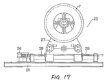
- Each of the right and left sprockets 7 is provided with a tensioning mechanism 23 which is as shown in Figs. 16 and 17. This will be described in more detail.
- the sprocket 7 and a hydraulic cylinder 24 are arranged in the middle of a rectangular frame 25 in such a manner that they are spaced from each other and are in parallel with each other.
- Four sprocket holders 26 are arranged near the four corners of the frame 25, respectively.
- Chains 28 are connected under tension, with the aid of the sprocket holders 26, between the piston rods 24a and 24a protruded from both ends of the hydraulic cylinder 24 and both sides of a bearing frame 27 provided below the sprocket 7, respectively.
- the tension of the chains 28 is detected by a tension detecting load cell 29.
- each of the clip chains is of the order of 40 to 60 meters.
- the conventional multistage tenter in order to reduce the time required for drying a film, it is necessary to increase the heating temperature. However, increase of the heating temperature may wrinkle the surface of the film. In order to effectively dry the film at a suitable, relatively low temperature, it is necessary to increase the length of the heating section, and accordingly to increase the length of the clip chains. If each clip chain is increased in length, then the number of chain links forming the clip chain is increased accordingly, with the result that the pitch errors of the chain links are accumulated, providing a large accumulative pitch error as a whole. This large accumulative pitch error will result in the difference in length between the right and left clip chains.
- the difference should be 10 mm or less per 100 m with the clip chains laid between the film inlet and the film outlet.
- the clip chain is of the order of 200 m, it is rather difficult to reduce the difference to 10 mm or less.
- a method is employed in which chain links substantially equal in hole pitch are selected as pairs, which are distributed uniformly to the right and left clip chains.
- to do so would take a lot of time and labor.
- the effect of the difference between the right and left clip chains is large where the direction of movement of the clip chains is changed by the sprockets.
- the right and left sprockets for changing the direction of movement of the clip chains are provided individually; that is, they are rotated separately, and accordingly the movements of the right and left clip chains are not synchronous with each other.
- the accumulative pitch errors of the right and left clip chains are not absorbed, and the difference in length of the right and left clip chains, which is due to the accumulative pitch errors, will form wrinkles on the film.
- the clip chain tensioning mechanisms are provided for the right and left sprockets, respectively.
- the tensions of the right and left clip chains are detected, so that the clip chain shorter is tensioned by the respective hydraulic cylinder more than the other.
- GB-A 2009273 discloses a tenter chain having chain links arranged at both sides of a sleeve roller embracing successive teeth of a sprocket.
- US-A 3748704 discloses a clamp for a biaxial stretching machine having opposed and longitudinally spaced rollers engaged in a guide rail.
- US-A 3828997 discloses an apparatus for positively conveying sheet materials.
- Each conveyor of the apparatus consists of transversely spaced chains of the roller type trained about sprockets and means are provided maintaining their approximate courses in gripping relation with the margins of the conveyed material.
- a chain tensioning means is provided for adjusting sprockets for each conveyor.
- US-A 3064795 discloses a sprocket chain for use in conveying arrangements of film processing apparatus.
- the sprocket chain consists of substantially U-shaped one-piece links preferably made by an injection molding process of at least slightly elastic synthetic plastic material.
- an object of this invention is to eliminate the above-described difficulties accompanying a conventional multistage tenter.
- an object of the invention is to provide a multi-stage tenter in which the right and left clip chains are tensioned simultaneously by one and the same drive source so that the shorter of the two clip chains is automatically tensioned more than the other; that is, the former is elongated more than the latter, whereby the pitch error is absorbed, and the film handled thereby is prevented from being wrinkled.
- Another object of the invention is to provide a multistage tenter in which the chain links of the clip chains are engaged with the middles of the coupling pins engaged with the teeth of the sprockets to deflect the coupling pins thereby to prevent the formation of wrinkles on the film handled thereby.
- the teeth of each of the sprockets are spaced in such a manner that they are removed every other one, and the chain links of the clip chains are engaged with the middle portions of coupling pins which are engaged with the teeth of the sprockets.
- a plurality of right and left sprockets for changing the direction of movement of said clip chains are connected through shafts, respectively, and drive sources are provided for the sprockets, respectively, to distribute the force of driving the clip chains to the sprockets.
- both edge portions of a belt-shaped film are supported by the clip chains, and the tensioning mechanism using one pressure source applies tensile force to the supports of a pair of right and left sprockets engaged with the clip chains simultaneously. Therefore, one of the clip chains which is shorter in length is automatically tensioned more than the other, as a result of which the two clip chains are made equal in length to each other, and accordingly the film is protected from being wrinkled.
- the drive sources when with both edge portions of a belt-shaped film supported by the right and left clip chains, the drive sources are operated to drive the plurality of sprockets for changing the direction of conveyance of the film, those sprockets are rotated synchronously because the right and left sprockets are connected through the respective shafts.
- the right and left clip chains are made equal in the speed of conveyance, and the power for driving the clip chains is distributed to the drive sources.
- the difference in length between the right and left clip chains attributing to the pitch errors of the latter is absorbed, whereby the variation in speed of the clip chains is reduced, and accordingly the difficulties are eliminated that the film is wrinkled and made non-uniform in thickness.
- a drying unit 1 is divided into a heating chamber 30 and a cooling chamber 31.
- a sprocket 32 for inserting a film 8 into the drying unit 1 is provided above a film inlet formed in one side wall of the drying unit 1 (which is the left side wall in Fig. 1).
- sprockets 33, 34 and 35 are provided in the heating chamber 30 which are used to change the direction of movement of the film 8 (hereinafter referred to as "direction changing sprockets 33, 34 and 35, when applicable), while a tension sprocket 36 and an idler sprocket 37 are arranged in the cooling chamber 31.
- the endless clip chains 2 are laid over those sprockets. Both edge portions of the film 8 are supported by the clip chains 2 through pins 14a formed on the pin plates 14, respectively.
- the clip chains are as shown in Figs. 2 and 3. That is, the clip chains are the same as those shown in Figs. 12 and 13 except the mounting structures of chain links 19 and coupling pins 11. Therefore, only the different components will be described here.
- each coupling pin 11 Both ends of each coupling pin 11 are fixedly secured to the side walls 10a of the clip body 10, and a spherical bearing 38 is mounted on the middle portion of the coupling pin 11, and a pair of rollers 18 and 18 are mounted on the coupling pin 11 in such a manner that they are located between the spherical bearing 38 and the side walls 10a of the clip body 10. And a chain link 19 is engaged with the spherical bearings 38 of adjacent clip bodies 10; that is, all the clip bodies 10 are coupled through the chain links 19.
- the rollers 18 are engaged with the sprockets 32.
- Each sprocket 32 as shown in Figs. 4 and 5, has teeth 32a in two lines. In each line, the teeth 32a are spaced in such a manner that the teeth are removed every other one in correspondence to the rotors 16 which are provided between the pairs of coupling pins 11.
- the other sprockets 33 through 37 are equal in structure to the above-described sprocket 32.
- each chain link 19 When each chain link 19 is engaged with the sprocket, the teeth of the latter are engaged with the rollers 18 mounted on both end portions of the chain link, and the tension is applied through the coupling pin 11 to the middle portion of the coupling pin 11, so that the spherical bearing 38 is slidably rotated around the coupling pin 11.
- the chain link 19 When going over a bend point of the film conveying path, the chain link 19 follows its displacement at the spherical part of the spherical bearing 38. Thus, the clip chains 2 are smoothly moved on.
- the chain links 19 are located near the side walls 10a of each clip chain body 10 supporting the coupling pin 19, and therefore the coupling pins 11 are scarcely deflected with a chain tension of the order of 400 kg.
- a deflection of about 0.003 mm has been obtained per coupling pin 11. This eliminates the difficulty that, in the conventional multistage tenter, the film 8 is liable to be wrinkled because the coupling pins 11 are low in deflection and accordingly the clip chains 2 are high in spring constant.
- the right and left sprockets 33 are mounted on both end portions of a coupling shaft 39, respectively, which is large in diameter and high in rigidity.
- the two end portions of the coupling shaft 39 are supported by bearings 21 and 21, respectively.
- One of the two end portions is extended so that it is coupled to an electric motor 42 through a coupling 40 and a speed reducer 41.
- Running rail brackets 43 are provided outside the sprockets 33 and 33, respectively.
- Each of the brackets 43 has two slide members 44 on its periphery.
- the slide members 44 are threadably engaged with threaded shafts 45 and 45 as shown in Fig. 6, in such a manner that, when the threaded shafts 45 are driven, the right and the left slide members 44 are in the opposite directions.
- the threaded shafts 45 are coupled through shafts 46, a coupling 47, worm speed reducers 48 to a geared electric motor 49. These components 45 through 49 form a distance adjusting device 22.
- the sprockets 35 and 35 and their distance adjusting device are the same in construction as the sprockets 33 and its distance adjusting device described above.
- the right and left sprockets for changing the direction of movement of the clip chains are rotated in synchronization. Accordingly, the right and left clip chains 2 are moved synchronously, and the pitch error of the clip chains 2 is forcibly corrected, or absorbed, when the clip chains 2 change the direction of movement at the sprockets. As a result, the difficulty is eliminated that, in the conventional multi-stage tenter, the film 8 is wrinkled because of the difference in length between the right and left clip chains 2.
- the Tension sprockets 36 are provided with a tensioning mechanism 23.
- the tensioning mechanism 23 comprises: a pressure source, namely, a hydraulic cylinder 24 arranged in the central region of a rectangular frame 25 in such a manner that it is extended longitudinally of the frame 25.
- the shaft 36a of the right and left tension sprockets 36 and 36 is laid below the hydraulic cylinder 24 in such a manner that it forms right angles with the latter 24.
- the right and left tension sprockets 36 and their bearings 21 are mounted on the end portions of the sprocket shaft 36a, respectively.
- the bearings 21 are supported by bearing supports 21a, respectively, which are so designed as to be slidable longitudinally of the frame.
- Eight sprockets holders 26 are installed on the frame 25 in such a manner that four of them are located at four corners of the frame 25, respectively, and two are positioned at the middle of each of the two sides of the frame 25.
- Two chains 28 are connected to each of the piston rods 24a and 24a of the hydraulic cylinder 24.
- Each of the two chains 28 is laid over the two sprocket holders 26 and 26 and connected to the side of the bearing 21 of the tension sprocket, as shown in Fig. 8.
- the sprocket holders 26 located at the four corners of the frame 25 the two provided respectively for the right and left sprockets 36 and 36 are provided with tension detecting load cells 29, respectively.
- the coupling shaft 39 is rotated through the speed reducer 41 and the coupling 40, so that the right and left sprockets 33 and 33 are rotated synchronously, and the clip chains 2 and 2 laid over the sprockets 33 are moved on.
- the film 8 supported on the clip chains 2 and 2 is conveyed smoothly because of the deflection of the coupling pin 11 and the stable contact of the chain links 19 attributing to the spherical bearings 38 mounted thereon.
- the distance between the sprockets 33 and 33 can be changed according to the width of a film 8 as follows: When the geared motor 49 is driven, the threaded shafts 45 and 45 are rotated, so that the right slide members 44 and 44 and the left slide member 44 and 44, which are engaged with the threaded shafts 45 and 45, are moved in the opposite directions; that is, the right and left running rail brackets 43 and 43 are moved in the opposite directions. Thus, the distance between the right and left sprockets 33 and 33 can be smoothly changed.
- the tensioning mechanism 23 operates as follows:
- the four chains 28 are connected between the piston rods 24a and 24a and the tension sprockets 36 and 36, as shown in Fig. 8. In this case, the connection of the chains 28 are carried out with the distances between the direction changing sprockets 35 and the tension sprockets 36 maintained equal to each other (in Fig. 1).
- the length of the clip chain 2 laid over the sprocket 36 (which is located lower in Fig. 8) is shorter than that of the clip chain 2 laid over the sprocket 36 (which is located upper in Fig. 8).
- the tension of the lower clip chain 2 is larger than that of the upper clip chain, so that the lower tension sprocket 36 is slid through the bearing support to the left in Fig. 8.
- the clip chain 2 laid over the lower tension sprocket is elongated, and the chain links 19 being coupled to the middle portions of the coupling pins 11, the latter 11 are deflected, thus absorbing the pitch error; that is, the clip chains 2 are made equal in length.
- a drying unit 1 is divided into a heating chamber 30 and a cooling chamber 31.
- a sprocket 32 for inserting a film 8 into the drying unit 1 is provided above a film inlet formed in one side wall of the drying unit 1 (which is the left side wall in Fig. 1).
- sprockets 33, 34 and 35 are provided in the heating chamber 30 which are used to change the direction of movement of the film 8 (hereinafter referred to as "direction changing sprockets 33, 34 and 35, when applicable), while a tension sprocket 36 and an idler sprocket 37 are arranged in the cooling chamber 31.
- the endless clip chains 2 are laid over those sprockets. Both edge portions of the film 8 are supported by the clip chains 2 through pins 14a formed on the pin plates 14, respectively.
- a sleeve 54 is engaged through a key 55 with a boss 53 extended horizontally from a disc 52 which has teeth 51.
- the sleeve 54 has the internal teeth of an involute spline 56 and slide bushings 57.
- the sleeve 54 is engaged with a boss 58 having the external teeth of the involute spline 56.
- the boss 58 is coupled through a key 59 to a coupling shaft 39 which is large in diameter and high in rigidity.
- the direction changing sprockets 33 are mounted on both end portions of the coupling shaft 39, which are supported by bearings 21, respectively.
- One of the end portions of the coupling shaft 39 is extended so that it is coupled through a coupling 40 to a speed reducer 41.
- the speed reducer 41 is coupled through a coupling 61 to a main electric motor 42, which is electrically connected to auxiliary electric motors (not shown) provided for the sprockets 33.
- Running rail brackets 43 are provided outside the sprockets 33, respectively.
- the brackets 43, as shown in Fig. 18, are mounted through bearings 60 on the sleeves 54.
- the other direction changing sprockets 34 and 35 are the same in construction as the above-described sprockets 33.
- Each of the running rail brackets 43 has two slide members 44 and 44 on its periphery. These slide members 44 are threadably engaged with threaded shafts 45 and 45 which are disposed in parallel with the coupling shaft 39 in such a manner that, when the shafts 45 are driven, the right slide members 44 and the left slide members 44 are moved in the opposite direction.
- the threaded shafts 45 are rotatably supported by frames 62, respectively, and are connected through shafts 46, worm speed reducers 48 and a coupling 47 provided between the speed reducers to a geared electric motor 49.
- the other direction changing sprockets are also provided with distance adjusting devices which are similar in construction to the above-described one provided for the sprockets 33.
- the multistage tenter, the second embodiment, thus constructed operates as follows:
- the main motor 42 When the main motor 42 is operated, the torque is transmitted through the coupling 61, the speed reducer 41 and the coupling 40 to the coupling shaft 39 to rotate the direction changing sprockets 35 and 35. Accordingly the clip chains 2 laid over the sprockets are moved, and accordingly the film 8 supported by the clip chains 2 are conveyed.
- the main motor 42 When the main motor 42 is driven, the auxiliary motors, being electrically connected to the main motor 42, are driven to rotate the sprockets connected thereto.
- Means for allowing each auxiliary motor to operate in synchronization with the main motor and for adjusting the output thereof is provided between the main motor and the auxiliary motor. Therefore, the power required for conveying the film may be distributed between the main motor and the auxiliary motors in a certain proportion. For instance, the main motor 42 may output 85% power, and the auxiliary motors 15% power.
- Fig. 19 is a graphical representation indicating one example of the relation between the irregularity of rotation of the sprocket 32 and the motor speed.
- the irregularity of rotation of the film inserting sprockets 32 is 1.6 to 5.0% with the motor speed in a range of 350 to 1750 rpm, and in the case where the direction changing sprockets 35 and 33 are driven, the irregularity of rotation is 1.0 to 3.1%, which is smaller by 1.0 to 1.8 %.
- the irregularity of rotation of the sprocket 32 being decreased, the film is protected from being wrinkled or from becoming uneven in thickness.
- the geared motor 49 When it is required to decrease the distance between the clip chains according to the width of a film to be handled, the geared motor 49 is operated, so that the torque thereof is applied through the worm speed reducers 48, the coupling 47, and the shafts 46 to the threaded shafts 45.
- the slide members 44 and the threaded shafts 45 engaged with the latter 44 are so threaded that, when the threaded shafts 45 are rotated, the right running rail bracket 43 coupled to the right slide members 44 and the left running rail bracket 43 coupled to the left slide members 44 are moved in the opposite directions.
- the brackets 43 As the brackets 43 are moved in this manner, the sleeves 54 coupled to the brackets 43 through the bearings 60 are moved, and accordingly the sprockets 33 coupled through the keys 55 to the sleeves are moved.
- the sleeves 54 are smoothly moved in the axial direction because, in each sprocket, the involute spline 56 is provided between the sleeve 54 and the boss 56, and the slide bushings 57 are provided between the sleeve 54 and the coupling shaft 39.
- the auxiliary motors are provided for the direction changing sprockets 33; however, they may be provided for the direction changing sprockets 34, or both of the sprockets 33 and 34. That is, the invention is not limited thereto or thereby.
- the tensioning mechanism for providing a tensile force by using one pressure source is provided for the supports of one pair of right and left sprockets engaged with the right and left clip chains, so as to slide the supports thereby to tension the clip chains simultaneously. Therefore, with the multistage tenter, the clip chain shorter in length is automatically increased in tension, whereby the pitch error between the two clip chains is absorbed with the result that the two clip chains are made equal in length. Hence, even when long chain lines are used, they are made equal in length, as a result of which webs such as belt-shaped films can be processed in short time, and the resultant products are excellent in quality having no wrinkles.
- the right and left sprockets engaged with the clip chains have the teeth which are arranged in two lines and spaced in such a manner that the teeth are removed every other one, and the chain links of the clip chains are engaged with the middle portions of the coupling pins 19. Therefore, the coupling pins are readily deflected, so that the clip chains can be effectively corrected in length by the tensioning mechanism, and can be smoothly moved.
Landscapes
- Physics & Mathematics (AREA)
- General Physics & Mathematics (AREA)
- Advancing Webs (AREA)
- Registering, Tensioning, Guiding Webs, And Rollers Therefor (AREA)
- Drying Of Solid Materials (AREA)
- Treatment Of Fiber Materials (AREA)
Description
- This invention relates to a multistage tenter used to process belt-shaped sheets or webs such as belt-shaped films.
- A conventional multistage tenter of this type is known as shown in Fig. 10. The multistage tenter has a
drying unit 1 in whichendless clip chains 2 are laid oversprockets sprockets 6 are driven by a drive source (not shown), so that twoclip chains 2 engaged with thesesprockets 3 through 7 as shown in Fig. 11 are driven, whereby a belt-shaped film 8 (hereinafter referred to merely as "afilm 8", when applicable) is inserted into thedrying unit 1 through a film inlet formed in its side wall. Thefilm 8 thus inserted is conveyed downwardly while changing the direction of movement (or being bent) so that it is dried in the drying unit. The film thus dried is moved out of the drying unit passing through a film removing roll 9. - The
clip chains 2 are constructed as shown in Figs. 12 and 13. Two coupling pins 11 are secured to theside walls 10a of eachclip body 10.Rotors 12 are provided at first ends of the coupling pins 11 in such a manner that they are disposed between the confronted surfaces ofguide rails 13 which are provided above and below therotors 12. Apin plate 14 is coupled to the other ends of the coupling pins 11.Rotors 15 androtors 16 are provided obliquely above and obliquely below each of therotors 12 in such a manner that they are abutted against theguide rails 13, as shown in Figs. 12 and 13. - Each coupling pin 11 is inserted into a
bushing 17, which is inserted into aroller 18. A pair ofchain links bushing 17 in such a manner that they are located on both sides of theroller 18. In Fig. 12,reference character 3a designates the teeth of the sprockets. Thesprockets clip chains 2 are equal in construction to one another. As shown in Figs. 14 and 15, the right andleft sprockets 4 are supported throughbearings 21 onshafts 20, anddistance adjusting device 22 for adjusting the distance between the right andleft sprockets 4 is provided below thebearings 22, respectively. - Each of the right and
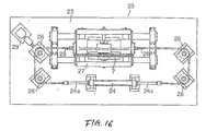
left sprockets 7 is provided with atensioning mechanism 23 which is as shown in Figs. 16 and 17. This will be described in more detail. Thesprocket 7 and ahydraulic cylinder 24 are arranged in the middle of arectangular frame 25 in such a manner that they are spaced from each other and are in parallel with each other. Foursprocket holders 26 are arranged near the four corners of theframe 25, respectively.Chains 28 are connected under tension, with the aid of thesprocket holders 26, between thepiston rods hydraulic cylinder 24 and both sides of a bearingframe 27 provided below thesprocket 7, respectively. The tension of thechains 28 is detected by a tension detectingload cell 29. - In the conventional multistage tenter thus constructed, each of the clip chains is of the order of 40 to 60 meters. With the conventional multistage tenter, in order to reduce the time required for drying a film, it is necessary to increase the heating temperature. However, increase of the heating temperature may wrinkle the surface of the film. In order to effectively dry the film at a suitable, relatively low temperature, it is necessary to increase the length of the heating section, and accordingly to increase the length of the clip chains. If each clip chain is increased in length, then the number of chain links forming the clip chain is increased accordingly, with the result that the pitch errors of the chain links are accumulated, providing a large accumulative pitch error as a whole. This large accumulative pitch error will result in the difference in length between the right and left clip chains. The difference should be 10 mm or less per 100 m with the clip chains laid between the film inlet and the film outlet. However, in the case where the clip chain is of the order of 200 m, it is rather difficult to reduce the difference to 10 mm or less. In order to meet the requirement, a method is employed in which chain links substantially equal in hole pitch are selected as pairs, which are distributed uniformly to the right and left clip chains. However, to do so would take a lot of time and labor. On the other hand, in the multistage tenter, the effect of the difference between the right and left clip chains is large where the direction of movement of the clip chains is changed by the sprockets.
- Furthermore in the conventional multistage tenter, the right and left sprockets for changing the direction of movement of the clip chains are provided individually; that is, they are rotated separately, and accordingly the movements of the right and left clip chains are not synchronous with each other. Hence, the accumulative pitch errors of the right and left clip chains are not absorbed, and the difference in length of the right and left clip chains, which is due to the accumulative pitch errors, will form wrinkles on the film.
- The clip chain tensioning mechanisms are provided for the right and left sprockets, respectively. The tensions of the right and left clip chains are detected, so that the clip chain shorter is tensioned by the respective hydraulic cylinder more than the other. However, it is rather difficult to adjust the tensions of the clip chains with their own hydraulic cylinders separately thereby to absorb the difference in length therebetween in order to prevent the formation of wrinkles on the film.
- GB-A 2009273 discloses a tenter chain having chain links arranged at both sides of a sleeve roller embracing successive teeth of a sprocket.
- US-A 3748704 discloses a clamp for a biaxial stretching machine having opposed and longitudinally spaced rollers engaged in a guide rail.
- US-A 3828997 discloses an apparatus for positively conveying sheet materials. Each conveyor of the apparatus consists of transversely spaced chains of the roller type trained about sprockets and means are provided maintaining their approximate courses in gripping relation with the margins of the conveyed material. A chain tensioning means is provided for adjusting sprockets for each conveyor.
- US-A 3064795 discloses a sprocket chain for use in conveying arrangements of film processing apparatus. The sprocket chain consists of substantially U-shaped one-piece links preferably made by an injection molding process of at least slightly elastic synthetic plastic material.
- Accordingly, an object of this invention is to eliminate the above-described difficulties accompanying a conventional multistage tenter.
- More specifically, an object of the invention is to provide a multi-stage tenter in which the right and left clip chains are tensioned simultaneously by one and the same drive source so that the shorter of the two clip chains is automatically tensioned more than the other; that is, the former is elongated more than the latter, whereby the pitch error is absorbed, and the film handled thereby is prevented from being wrinkled.
- Another object of the invention is to provide a multistage tenter in which the chain links of the clip chains are engaged with the middles of the coupling pins engaged with the teeth of the sprockets to deflect the coupling pins thereby to prevent the formation of wrinkles on the film handled thereby.
- The foregoing objects and other objects are achieved by the provision of a multistage tenter in accordance with
claim 1. - In the multistage tenter, the teeth of each of the sprockets are spaced in such a manner that they are removed every other one, and the chain links of the clip chains are engaged with the middle portions of coupling pins which are engaged with the teeth of the sprockets.
- Furthermore in the multistage tenter, a plurality of right and left sprockets for changing the direction of movement of said clip chains are connected through shafts, respectively, and drive sources are provided for the sprockets, respectively, to distribute the force of driving the clip chains to the sprockets.
- In the multistage tenter of the invention, both edge portions of a belt-shaped film are supported by the clip chains, and the tensioning mechanism using one pressure source applies tensile force to the supports of a pair of right and left sprockets engaged with the clip chains simultaneously. Therefore, one of the clip chains which is shorter in length is automatically tensioned more than the other, as a result of which the two clip chains are made equal in length to each other, and accordingly the film is protected from being wrinkled.
- Furthermore in the multistage tenter, since the chain links of the clip chains are engaged with the middle portions of the coupling pins, the latter are deflected so as to make the right and left clip chains equal in length with small tensile force.
- Moreover in the multistage tenter of the invention, when with both edge portions of a belt-shaped film supported by the right and left clip chains, the drive sources are operated to drive the plurality of sprockets for changing the direction of conveyance of the film, those sprockets are rotated synchronously because the right and left sprockets are connected through the respective shafts. Hence, the right and left clip chains are made equal in the speed of conveyance, and the power for driving the clip chains is distributed to the drive sources. As a result, the difference in length between the right and left clip chains attributing to the pitch errors of the latter is absorbed, whereby the variation in speed of the clip chains is reduced, and accordingly the difficulties are eliminated that the film is wrinkled and made non-uniform in thickness.
- The nature, principle and utility of the invention will become more apparent from the following detailed descriptions and the appended claims when read in conjunction with the accompanying drawings.
-
- In the accompanying drawings:
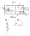
- Fig. 1 is a sectional side view showing a part of a multistage tenter, a first embodiment of this invention;
- Fig. 2 is an enlarged plan view showing a clip chain in the multistage tenter according to the invention;
- Fig. 3 is a sectional view taken along line A-A in Fig. 2;
- Figs. 4 and 5 is a sectional side view and a front view showing a part of a sprocket in the multistage tenter according to the invention, respectively;
- Fig. 6 is a plan view showing a pair of direction changing sprockets with a distance adjusting device in the multistage tenter according to the invention, and
- Fig. 7 is a front elevation as viewed in the direction of the arrow B;
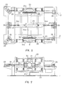
- FIGS, 8 and 9 are a plan view and a side view showing a tensioning mechanism in the multistage tenter of the invention;
- Fig. 10 is a sectional side view showing a part of a conventional multistage tenter;
- Fig. 11 is a perspective view showing clip chains in the conventional multistage tenter;
- Fig. 12 is an enlarged plan view showing the conventional clip chain;
- Fig. 13 is a sectional view taken along line C-C in Fig. 12;
- Figs. 14 and 15 are a front view and a side view (with parts cut away) showing a direction changing sprocket in the conventional multistage tenter, respectively;
- Figs. 16 and 17 are a plan view and a side view showing a tensioning mechanism in the conventional multistage tenter, respectively;
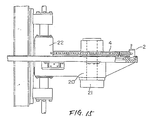
- Fig. 18 is a sectional side view showing a direction changing sprocket and its relevant components in a multistage tenter, a second embodiment of the invention; and
- Fig. 19 is a graphical representation indicating the relation between the speed of an electric motor and the irregularity of rotation of sprockets (32) in the second embodiment of the invention.
- A first embodiment of this invention will be described with reference to Figs. 1 through 9, in which components equivalent to those which have been previously described with reference to Figs. 10 through 17 are therefore designated by the same reference numerals or characters.
- As shown in Fig. 1, a
drying unit 1 is divided into aheating chamber 30 and acooling chamber 31. Asprocket 32 for inserting afilm 8 into thedrying unit 1 is provided above a film inlet formed in one side wall of the drying unit 1 (which is the left side wall in Fig. 1). Furthermore sprockets 33, 34 and 35 are provided in theheating chamber 30 which are used to change the direction of movement of the film 8 (hereinafter referred to as "direction changing sprockets tension sprocket 36 and anidler sprocket 37 are arranged in the coolingchamber 31. Theendless clip chains 2 are laid over those sprockets. Both edge portions of thefilm 8 are supported by theclip chains 2 throughpins 14a formed on thepin plates 14, respectively. - The clip chains are as shown in Figs. 2 and 3. That is, the clip chains are the same as those shown in Figs. 12 and 13 except the mounting structures of
chain links 19 and coupling pins 11. Therefore, only the different components will be described here. - Both ends of each coupling pin 11 are fixedly secured to the
side walls 10a of theclip body 10, and aspherical bearing 38 is mounted on the middle portion of the coupling pin 11, and a pair ofrollers spherical bearing 38 and theside walls 10a of theclip body 10. And achain link 19 is engaged with thespherical bearings 38 ofadjacent clip bodies 10; that is, all theclip bodies 10 are coupled through the chain links 19. - The
rollers 18 are engaged with thesprockets 32. Eachsprocket 32, as shown in Figs. 4 and 5, hasteeth 32a in two lines. In each line, theteeth 32a are spaced in such a manner that the teeth are removed every other one in correspondence to therotors 16 which are provided between the pairs of coupling pins 11. Theother sprockets 33 through 37 are equal in structure to the above-describedsprocket 32. - When each
chain link 19 is engaged with the sprocket, the teeth of the latter are engaged with therollers 18 mounted on both end portions of the chain link, and the tension is applied through the coupling pin 11 to the middle portion of the coupling pin 11, so that thespherical bearing 38 is slidably rotated around the coupling pin 11. When going over a bend point of the film conveying path, thechain link 19 follows its displacement at the spherical part of thespherical bearing 38. Thus, theclip chains 2 are smoothly moved on. - In the conventional multistage tenter, the chain links 19 are located near the
side walls 10a of eachclip chain body 10 supporting thecoupling pin 19, and therefore the coupling pins 11 are scarcely deflected with a chain tension of the order of 400 kg. On the other hand, in the case of the chain links 19 in the above-described embodiment of the invention, a deflection of about 0.003 mm has been obtained per coupling pin 11. This eliminates the difficulty that, in the conventional multistage tenter, thefilm 8 is liable to be wrinkled because the coupling pins 11 are low in deflection and accordingly theclip chains 2 are high in spring constant. - Now the sprockets for changing the direction of movement of the clip chains will be described.
- As shown in Figs. 6 and 7, the right and left
sprockets 33 are mounted on both end portions of acoupling shaft 39, respectively, which is large in diameter and high in rigidity. The two end portions of thecoupling shaft 39 are supported bybearings electric motor 42 through acoupling 40 and aspeed reducer 41. - Running
rail brackets 43 are provided outside thesprockets brackets 43 has twoslide members 44 on its periphery. Theslide members 44 are threadably engaged with threadedshafts shafts 45 are driven, the right and theleft slide members 44 are in the opposite directions. The threadedshafts 45 are coupled throughshafts 46, acoupling 47,worm speed reducers 48 to a gearedelectric motor 49. Thesecomponents 45 through 49 form adistance adjusting device 22. - The
sprockets sprockets 33 and its distance adjusting device described above. - Hence, the right and left sprockets for changing the direction of movement of the clip chains are rotated in synchronization. Accordingly, the right and left
clip chains 2 are moved synchronously, and the pitch error of theclip chains 2 is forcibly corrected, or absorbed, when theclip chains 2 change the direction of movement at the sprockets. As a result, the difficulty is eliminated that, in the conventional multi-stage tenter, thefilm 8 is wrinkled because of the difference in length between the right and leftclip chains 2. - The Tension sprockets 36, as shown in Figs. 8 and 9, are provided with a
tensioning mechanism 23. Thetensioning mechanism 23 comprises: a pressure source, namely, ahydraulic cylinder 24 arranged in the central region of arectangular frame 25 in such a manner that it is extended longitudinally of theframe 25. Theshaft 36a of the right and lefttension sprockets hydraulic cylinder 24 in such a manner that it forms right angles with the latter 24. More specifically, the right and lefttension sprockets 36 and theirbearings 21 are mounted on the end portions of thesprocket shaft 36a, respectively. Thebearings 21 are supported by bearingsupports 21a, respectively, which are so designed as to be slidable longitudinally of the frame. Eightsprockets holders 26 are installed on theframe 25 in such a manner that four of them are located at four corners of theframe 25, respectively, and two are positioned at the middle of each of the two sides of theframe 25. - Two
chains 28 are connected to each of thepiston rods hydraulic cylinder 24. Each of the twochains 28 is laid over the twosprocket holders sprocket holders 26 located at the four corners of theframe 25, the two provided respectively for the right and leftsprockets load cells 29, respectively. - Now, the operation of the multistage tenter thus constructed will be described.
- When the
motor 42 is driven, thecoupling shaft 39 is rotated through thespeed reducer 41 and thecoupling 40, so that the right and leftsprockets clip chains sprockets 33 are moved on. Thus, thefilm 8 supported on theclip chains spherical bearings 38 mounted thereon. - The distance between the
sprockets film 8 as follows: When the gearedmotor 49 is driven, the threadedshafts right slide members left slide member shafts rail brackets sprockets - The
tensioning mechanism 23 operates as follows: - The four
chains 28 are connected between thepiston rods tension sprockets chains 28 are carried out with the distances between thedirection changing sprockets 35 and thetension sprockets 36 maintained equal to each other (in Fig. 1). - Then, while the tensions of the
chains 28 being detected with theload cells piston rod 24a is moved in the direction of the arrow (to the right) in Fig. 8, thereby to tension thechains - It is assumed that the length of the
clip chain 2 laid over the sprocket 36 (which is located lower in Fig. 8) is shorter than that of theclip chain 2 laid over the sprocket 36 (which is located upper in Fig. 8). In this case, the tension of thelower clip chain 2 is larger than that of the upper clip chain, so that thelower tension sprocket 36 is slid through the bearing support to the left in Fig. 8. Accordingly, theclip chain 2 laid over the lower tension sprocket is elongated, and the chain links 19 being coupled to the middle portions of the coupling pins 11, the latter 11 are deflected, thus absorbing the pitch error; that is, theclip chains 2 are made equal in length. - A second embodiment of the invention will be described with reference to Figs. 1, 18, 6, 7 and 19, in which components which are equivalent to those which have been described with reference to Figs. 10, 11, 14 and 15 are therefore designated by the same reference numerals or characters.
- As shown in Fig. 1, a
drying unit 1 is divided into aheating chamber 30 and acooling chamber 31. Asprocket 32 for inserting afilm 8 into thedrying unit 1 is provided above a film inlet formed in one side wall of the drying unit 1 (which is the left side wall in Fig. 1). Furthermore sprockets 33, 34 and 35 are provided in theheating chamber 30 which are used to change the direction of movement of the film 8 (hereinafter referred to as "direction changing sprockets tension sprocket 36 and anidler sprocket 37 are arranged in the coolingchamber 31. Theendless clip chains 2 are laid over those sprockets. Both edge portions of thefilm 8 are supported by theclip chains 2 throughpins 14a formed on thepin plates 14, respectively. - The direction changing sprockets will be described. As a typical example of these sprockets, the
sprockets 33 will be described. As shown in Fig. 18, a sleeve 54 is engaged through a key 55 with aboss 53 extended horizontally from adisc 52 which hasteeth 51. The sleeve 54 has the internal teeth of aninvolute spline 56 andslide bushings 57. The sleeve 54 is engaged with aboss 58 having the external teeth of theinvolute spline 56. Theboss 58 is coupled through a key 59 to acoupling shaft 39 which is large in diameter and high in rigidity. As shown in Fig. 6, thedirection changing sprockets 33 are mounted on both end portions of thecoupling shaft 39, which are supported bybearings 21, respectively. One of the end portions of thecoupling shaft 39 is extended so that it is coupled through acoupling 40 to aspeed reducer 41. Thespeed reducer 41 is coupled through acoupling 61 to a mainelectric motor 42, which is electrically connected to auxiliary electric motors (not shown) provided for thesprockets 33. - Running
rail brackets 43 are provided outside thesprockets 33, respectively. Thebrackets 43, as shown in Fig. 18, are mounted throughbearings 60 on the sleeves 54. The otherdirection changing sprockets sprockets 33. - Now, a
distance adjusting device 22 provided for changing the distance between the right and leftsprockets 33 will be described. - Each of the running
rail brackets 43 has twoslide members slide members 44 are threadably engaged with threadedshafts coupling shaft 39 in such a manner that, when theshafts 45 are driven, theright slide members 44 and theleft slide members 44 are moved in the opposite direction. The threadedshafts 45 are rotatably supported byframes 62, respectively, and are connected throughshafts 46,worm speed reducers 48 and acoupling 47 provided between the speed reducers to a gearedelectric motor 49. - The other direction changing sprockets are also provided with distance adjusting devices which are similar in construction to the above-described one provided for the
sprockets 33. - The multistage tenter, the second embodiment, thus constructed operates as follows:
- When the
main motor 42 is operated, the torque is transmitted through thecoupling 61, thespeed reducer 41 and thecoupling 40 to thecoupling shaft 39 to rotate thedirection changing sprockets clip chains 2 laid over the sprockets are moved, and accordingly thefilm 8 supported by theclip chains 2 are conveyed. When themain motor 42 is driven, the auxiliary motors, being electrically connected to themain motor 42, are driven to rotate the sprockets connected thereto. - Means for allowing each auxiliary motor to operate in synchronization with the main motor and for adjusting the output thereof is provided between the main motor and the auxiliary motor. Therefore, the power required for conveying the film may be distributed between the main motor and the auxiliary motors in a certain proportion. For instance, the
main motor 42 may output 85% power, and theauxiliary motors 15% power. - Fig. 19 is a graphical representation indicating one example of the relation between the irregularity of rotation of the
sprocket 32 and the motor speed. As is apparent from Fig. 19, when thedirection changing sprockets 35 are driven alone, the irregularity of rotation of thefilm inserting sprockets 32 is 1.6 to 5.0% with the motor speed in a range of 350 to 1750 rpm, and in the case where thedirection changing sprockets sprocket 32 being decreased, the film is protected from being wrinkled or from becoming uneven in thickness. - The operation of the
distance adjusting device 22 will be described. - When it is required to decrease the distance between the clip chains according to the width of a film to be handled, the geared
motor 49 is operated, so that the torque thereof is applied through theworm speed reducers 48, thecoupling 47, and theshafts 46 to the threadedshafts 45. As was described before, theslide members 44 and the threadedshafts 45 engaged with the latter 44 are so threaded that, when the threadedshafts 45 are rotated, the right runningrail bracket 43 coupled to theright slide members 44 and the left runningrail bracket 43 coupled to theleft slide members 44 are moved in the opposite directions. As thebrackets 43 are moved in this manner, the sleeves 54 coupled to thebrackets 43 through thebearings 60 are moved, and accordingly thesprockets 33 coupled through the keys 55 to the sleeves are moved. - In this operation, the sleeves 54 are smoothly moved in the axial direction because, in each sprocket, the
involute spline 56 is provided between the sleeve 54 and theboss 56, and theslide bushings 57 are provided between the sleeve 54 and thecoupling shaft 39. - In the above description, the auxiliary motors are provided for the
direction changing sprockets 33; however, they may be provided for thedirection changing sprockets 34, or both of thesprockets - As was described above, in the multistage tenter of the invention, the tensioning mechanism for providing a tensile force by using one pressure source is provided for the supports of one pair of right and left sprockets engaged with the right and left clip chains, so as to slide the supports thereby to tension the clip chains simultaneously. Therefore, with the multistage tenter, the clip chain shorter in length is automatically increased in tension, whereby the pitch error between the two clip chains is absorbed with the result that the two clip chains are made equal in length. Hence, even when long chain lines are used, they are made equal in length, as a result of which webs such as belt-shaped films can be processed in short time, and the resultant products are excellent in quality having no wrinkles.
- Furthermore, according to the invention, the right and left sprockets engaged with the clip chains have the teeth which are arranged in two lines and spaced in such a manner that the teeth are removed every other one, and the chain links of the clip chains are engaged with the middle portions of the coupling pins 19. Therefore, the coupling pins are readily deflected, so that the clip chains can be effectively corrected in length by the tensioning mechanism, and can be smoothly moved.
- While there has been described in connection with the preferred embodiments of this invention, it will be obvious to those skilled in the art that various changes and modifications may be made therein without departing from the invention, and it is aimed, therefore, to cover in the appended claims all such changes and modification as fall within the scope of the invention.
Claims (8)
- A multistage tenter having right and left clip chains (2,2) for conveying a belt-shaped film (8) in a drying unit (1), and a tensioning mechanism (23) using a pressure source (24) for applying a tensile force, said tensioning mechanism (23) being provided for a support (21a) of a sprocket (36) engaged with said clip chain (2),
characterized in that:
said tensioning mechanism (23) is provided for the supports (21a) of a pair of right and left sprockets (36) engaged with said clip chains (2) respectively, to slide said supports (21a) and to tension said right and left clip chains (2) simultaneously by using one pressure source (24). - A multistage tenter as claimed in claim 1, in which said right and left sprockets (36) engaged with said clip chains (2) each have teeth (32a) which are arranged confronted in two lines and spaced in each line in such a manner that every second tooth is removed and said clip chains (2) have chain links (19) which are engaged with the middle portions of coupling pins (11) which are engaged with said teeth (32a) of said sprockets (36).
- A multistage tenter as claimed in claim 1 or 2, comprising
a plurality of right and left sprockets (33, 34, 35) for changing the direction of movement of said clip chains (2), said sprockets (33, 34, 35) being connected through shafts (39), respectively, and
a driving means (42) provided for at least one of said sprockets (33, 34, 35). - A multistage tenter as claimed in one of claims 1 to 3 wherein said right and left endless clip chains (2) have a plurality of rotors (12, 15, 16) being abutted against guide rails (13) respectively.
- The multistage tenter as claimed in one of claims 1 to 4, further comprising auxiliary driving means (42', 42'') for driving another pair of sprockets, in which the power required for conveying said film (8) may be distributed between said driving means (42) and said auxiliary driving means (42', 42'') in a certain proportion.
- The multistage tenter as claimed in one of claims 1 to 5, further comprising a distance adjusting device (22) for adjusting a distance between one pair of sprockets (33).
- The multistage tenter as claimed in one of claims 3 to 6, wherein said shaft (39) is made as thick in diameter as having a high rigidity.
- The multistage tenter as claimed in claim 4, wherein said drying unit (1) comprises a heating chamber (30) and a cooling chamber (31).
Applications Claiming Priority (4)
| Application Number | Priority Date | Filing Date | Title |
|---|---|---|---|
| JP333110/88 | 1988-12-28 | ||
| JP33311088A JP2662002B2 (en) | 1988-12-28 | 1988-12-28 | Multi-stage tenter |
| JP65189A JP2662010B2 (en) | 1989-01-05 | 1989-01-05 | Multi-stage tenter |
| JP651/89 | 1989-01-05 |
Publications (3)
| Publication Number | Publication Date |
|---|---|
| EP0376325A2 EP0376325A2 (en) | 1990-07-04 |
| EP0376325A3 EP0376325A3 (en) | 1991-06-26 |
| EP0376325B1 true EP0376325B1 (en) | 1994-11-30 |
Family
ID=26333669
Family Applications (1)
| Application Number | Title | Priority Date | Filing Date |
|---|---|---|---|
| EP89124100A Expired - Lifetime EP0376325B1 (en) | 1988-12-28 | 1989-12-28 | Multistage tenter |
Country Status (3)
| Country | Link |
|---|---|
| US (1) | US5129163A (en) |
| EP (1) | EP0376325B1 (en) |
| DE (1) | DE68919666T2 (en) |
Cited By (1)
| Publication number | Priority date | Publication date | Assignee | Title |
|---|---|---|---|---|
| CN110986540A (en) * | 2019-11-29 | 2020-04-10 | 刘鹏刚 | Leveling and drying device for production of non-woven fabric paper diapers |
Families Citing this family (5)
| Publication number | Priority date | Publication date | Assignee | Title |
|---|---|---|---|---|
| JP2849836B2 (en) * | 1989-10-31 | 1999-01-27 | 富士写真フイルム株式会社 | Application method |
| US5287637A (en) * | 1992-03-27 | 1994-02-22 | The Dow Chemical Company | Apparatus to dry/heat treat continuous web stock of film |
| JP3681202B2 (en) * | 1995-10-20 | 2005-08-10 | 株式会社ユポ・コーポレーション | Tenter oven |
| US5815763A (en) * | 1996-03-28 | 1998-09-29 | Noritsu Koki Co., Ltd. | Conveying apparatus for photosensitive material |
| CN112728025B (en) * | 2020-12-25 | 2022-08-05 | 石狮市卓诚机械自动化设备有限责任公司 | Simple adjusting mechanism for chain tension |
Citations (2)
| Publication number | Priority date | Publication date | Assignee | Title |
|---|---|---|---|---|
| US3748704A (en) * | 1972-01-04 | 1973-07-31 | Kampf Maschf Erwin | Clamp for biaxial stretching machines |
| GB2009273A (en) * | 1977-12-16 | 1979-06-13 | Marshall & Williams Co | Tentering clip chain |
Family Cites Families (6)
| Publication number | Priority date | Publication date | Assignee | Title |
|---|---|---|---|---|
| US3064795A (en) * | 1959-06-26 | 1962-11-20 | Agfa Ag | Elastic chain for film processing apparatus and the like |
| US3149003A (en) * | 1960-04-18 | 1964-09-15 | Huyck Corp | Apparatus for treating endless fabrics |
| US3296712A (en) * | 1964-08-07 | 1967-01-10 | Hans W Sachs | Gripper drying tunnels |
| US3828997A (en) * | 1973-05-30 | 1974-08-13 | United Ind Syndicate | Apparatus for positively conveying sheet materials |
| US4231164A (en) * | 1978-08-31 | 1980-11-04 | Eastman Kodak Company | Apparatus and method for uniformly heating or cooling a moving web |
| US4316309A (en) * | 1979-10-09 | 1982-02-23 | Marshall And Williams Company | Tentering clip chain |
-
1989
- 1989-12-28 EP EP89124100A patent/EP0376325B1/en not_active Expired - Lifetime
- 1989-12-28 US US07/458,261 patent/US5129163A/en not_active Expired - Lifetime
- 1989-12-28 DE DE68919666T patent/DE68919666T2/en not_active Expired - Lifetime
Patent Citations (2)
| Publication number | Priority date | Publication date | Assignee | Title |
|---|---|---|---|---|
| US3748704A (en) * | 1972-01-04 | 1973-07-31 | Kampf Maschf Erwin | Clamp for biaxial stretching machines |
| GB2009273A (en) * | 1977-12-16 | 1979-06-13 | Marshall & Williams Co | Tentering clip chain |
Cited By (1)
| Publication number | Priority date | Publication date | Assignee | Title |
|---|---|---|---|---|
| CN110986540A (en) * | 2019-11-29 | 2020-04-10 | 刘鹏刚 | Leveling and drying device for production of non-woven fabric paper diapers |
Also Published As
| Publication number | Publication date |
|---|---|
| EP0376325A2 (en) | 1990-07-04 |
| US5129163A (en) | 1992-07-14 |
| DE68919666T2 (en) | 1995-04-06 |
| DE68919666D1 (en) | 1995-01-12 |
| EP0376325A3 (en) | 1991-06-26 |
Similar Documents
| Publication | Publication Date | Title |
|---|---|---|
| JPH0577583B2 (en) | ||
| US5129163A (en) | Multistage tenter | |
| TWI764722B (en) | An apparatus and a method for cutting a web of woven sheet material | |
| US5390398A (en) | Foil stretching machine for shrinking foils | |
| US3537936A (en) | Tire fabric alignment mechanism | |
| JP2662010B2 (en) | Multi-stage tenter | |
| CN219506989U (en) | Continuous transfer device of panel | |
| US4947529A (en) | Expander for tubular fabric | |
| JP2662002B2 (en) | Multi-stage tenter | |
| KR900004044B1 (en) | Expanding feeder of cloth | |
| US5743026A (en) | Drying device with improved guide for rotary cut wood veneer | |
| EP0747312A2 (en) | Folding apparatus superstructure | |
| EP0441484A2 (en) | Method of guiding a web through a dryer and apparatus for carrying out the method | |
| GB104720A (en) | Improvements in the Treatment of Dough. | |
| JPS6310051B2 (en) | ||
| CN120228335B (en) | A sawing device | |
| US4766650A (en) | Traveling flat mounting means | |
| CN223752079U (en) | Sanitary article conveyor | |
| JP2664752B2 (en) | Belt straightening method and apparatus in a molding machine that performs pressure molding between belts | |
| EP0087399A1 (en) | Apparatus for transversely stretching a foil of plastic material | |
| CN110758851A (en) | An automatic adjustment side baffle device | |
| RU1812125C (en) | Plant for biaxial orientation of polymeric films | |
| JPS63168335A (en) | Device for tentering cord material | |
| JPH0513760B2 (en) | ||
| JPH036429Y2 (en) |
Legal Events
| Date | Code | Title | Description |
|---|---|---|---|
| PUAI | Public reference made under article 153(3) epc to a published international application that has entered the european phase |
Free format text: ORIGINAL CODE: 0009012 |
|
| AK | Designated contracting states |
Kind code of ref document: A2 Designated state(s): DE NL |
|
| PUAL | Search report despatched |
Free format text: ORIGINAL CODE: 0009013 |
|
| AK | Designated contracting states |
Kind code of ref document: A3 Designated state(s): DE NL |
|
| 17P | Request for examination filed |
Effective date: 19911211 |
|
| 17Q | First examination report despatched |
Effective date: 19930603 |
|
| GRAA | (expected) grant |
Free format text: ORIGINAL CODE: 0009210 |
|
| AK | Designated contracting states |
Kind code of ref document: B1 Designated state(s): DE NL |
|
| REF | Corresponds to: |
Ref document number: 68919666 Country of ref document: DE Date of ref document: 19950112 |
|
| PLBE | No opposition filed within time limit |
Free format text: ORIGINAL CODE: 0009261 |
|
| STAA | Information on the status of an ep patent application or granted ep patent |
Free format text: STATUS: NO OPPOSITION FILED WITHIN TIME LIMIT |
|
| 26N | No opposition filed | ||
| PGFP | Annual fee paid to national office [announced via postgrant information from national office to epo] |
Ref country code: NL Payment date: 20081215 Year of fee payment: 20 |
|
| PGFP | Annual fee paid to national office [announced via postgrant information from national office to epo] |
Ref country code: DE Payment date: 20081229 Year of fee payment: 20 |
|
| PG25 | Lapsed in a contracting state [announced via postgrant information from national office to epo] |
Ref country code: NL Free format text: LAPSE BECAUSE OF EXPIRATION OF PROTECTION Effective date: 20091228 |
|
| NLV7 | Nl: ceased due to reaching the maximum lifetime of a patent |
Effective date: 20091228 |