EP0376259B1 - Low NOx boiler - Google Patents
Low NOx boiler Download PDFInfo
- Publication number
- EP0376259B1 EP0376259B1 EP89123973A EP89123973A EP0376259B1 EP 0376259 B1 EP0376259 B1 EP 0376259B1 EP 89123973 A EP89123973 A EP 89123973A EP 89123973 A EP89123973 A EP 89123973A EP 0376259 B1 EP0376259 B1 EP 0376259B1
- Authority
- EP
- European Patent Office
- Prior art keywords
- premixture
- flame
- combustion
- burner
- nozzle
- Prior art date
- Legal status (The legal status is an assumption and is not a legal conclusion. Google has not performed a legal analysis and makes no representation as to the accuracy of the status listed.)
- Expired - Lifetime
Links
Images




Classifications
-
- F—MECHANICAL ENGINEERING; LIGHTING; HEATING; WEAPONS; BLASTING
- F23—COMBUSTION APPARATUS; COMBUSTION PROCESSES
- F23D—BURNERS
- F23D23/00—Assemblies of two or more burners
-
- F—MECHANICAL ENGINEERING; LIGHTING; HEATING; WEAPONS; BLASTING
- F22—STEAM GENERATION
- F22B—METHODS OF STEAM GENERATION; STEAM BOILERS
- F22B21/00—Water-tube boilers of vertical or steeply-inclined type, i.e. the water-tube sets being arranged vertically or substantially vertically
- F22B21/34—Water-tube boilers of vertical or steeply-inclined type, i.e. the water-tube sets being arranged vertically or substantially vertically built-up from water tubes grouped in panel form surrounding the combustion chamber, i.e. radiation boilers
- F22B21/346—Horizontal radiation boilers
-
- F—MECHANICAL ENGINEERING; LIGHTING; HEATING; WEAPONS; BLASTING
- F22—STEAM GENERATION
- F22B—METHODS OF STEAM GENERATION; STEAM BOILERS
- F22B31/00—Modifications of boiler construction, or of tube systems, dependent on installation of combustion apparatus; Arrangements or dispositions of combustion apparatus
Definitions
- the flame of the premixture burner is shorter than the diffusion flame, and therefore, the boiler need not be made large in size.
- Each of these burners comprises a premixture injection nozzle 2, an air damper 7, a rectifier plate 3, an air supply pipe 5, and a fuel nozzle 4.
- the fuel nozzle 4 has a plurality of openings, through which the fuel is dispersed and fed into the air flow.
- the zone downstream of the fuel nozzle 4 is the mixing zone.
- the rectifier plate 3, which is a honeycomb-structured resistor, has a rectifying function to form a flow of a uniform speed distribution and also has a function to prevent a backfire of the premixture flame since the outlet velocity is increased as the passage cross section is reduced here.
- a strip-shaped flame holder 1 is disposed near the outlet of the nozzle 2 to extend perpendicular to a direction of the mainstream of the mixture.
- the air nozzle 36 has a swirl flow generator 37 mounted therein so as to control the swirl strength of combustion air.
- the premixture flame burner 1000 has a fuel nozzle 39 for premixture combustion disposed upstream of the premixture injection outlet 32.
- the gaseous fuel from the fuel nozzle 39 and the combustion air from an air supply pipe 40 are mixed to form a uniform premixture through a Venturi portion 41.
- the second diffusion flame burner 600 is disposed coaxially with the premixture injection outlet 32, and a fuel nozzle 45 is disposed coaxially with the diffusion flame burner 600.
- An air nozzle 46 is disposed to surround the fuel nozzle 45.
- the air nozzle 46 is provided with a swirl flow generator 44 which serves to shorten the diffusion flame of the second diffusion flame burner.
- the premixture when no rectifying means 59 is provided (the solid line 63), the premixture accumulates near the outer periphery of the outlet 48 due to a centrifugal force caused by the swirl flow generator 57, so that the premixture is not accumulated above the flame holder 47. Consequently, the premixture flame is located at the outer periphery of the outlet 48.
- the high-temperature exhaust gas caused by the premixture flame is drawn into the negative pressure zone extending around the center portion of the outlet 48, so that a flame is formed from within the outlet 48. Raised is a problem that the flame holder 47 deteriorates as it it heated from the upstream side thereof.
- the upper flue 114d includes a second air preheater 124 provided downstream of the openings, an unburnt gas combustor 126 provided downstrem of the second air preheater 124, and a first air preheater 123 provided downstream of the unburnt gas combustor 126.
- the first air preheater 123 and the second air preheater 124 are almost identical in constuction.
- the end face of the upstream side of the nozzle 208 is connected to the burner side wall, while the end face of the upstream side of the nozzle 209 is connected to a premixture side wall 211 provided on a side of the burner side wall 147 which is closer to the furnace.
- a plurality of resistor type swirl vanes 206 are mounted in an annular space defined by the burner side wall 147 and the premixture side wall 211.
- Each vane is provided integrally with a support post 207.
- the post 207 is mounted with its axis parallel with the generating line of a cylinder constituting the primary combustion chamber outer wall 142, and the opposite ends of the post 207 are rotatably born in bearing holes formed in the burner side wall 147 and the premixture side wall 211.
Landscapes
- Engineering & Computer Science (AREA)
- Chemical & Material Sciences (AREA)
- Combustion & Propulsion (AREA)
- Mechanical Engineering (AREA)
- General Engineering & Computer Science (AREA)
- Physics & Mathematics (AREA)
- Thermal Sciences (AREA)
Description
- The invention relates to a low-NOx boiler according to the preamble of
claim 1. Such a boiler uses a gaseous fuel and is suitable for reducing the concentration of nitrogen oxides (hereinafter referred to as NOx) exhausted therefrom when the fuel is burnt. - The emission control of NOx which causes photochemical smog becomes severer year after year. The development of technologies for the reduction of the exhaust of NOx has been pushed forward actively. The fuel for boilers, which produces less pollutants during combustion, is liquefied natural gas (LNG) and so on. The NOx which is produced when a gaseous fuel with less nitrogen contents is burnt is thermal NOx produced by the oxidation of nitrogen in the air supplied for combustion in a high-temperature atmosphere. The generation of thermal NOx highly depends on the temperature, and the thermal NOx increases as the flame temperature rises. The flame temperature varies according to the mixing ratio of fuel to combustion air, i.e. the excess air ratio (air quantity/theoretical air quantity), and is highest when the fuel is burnt with an adequate quantity of air (theoretical air quantity), neither excessive nor insufficient, for complete combustion.
- In an ordinary gaseous fuel boiler, diffusion combustion is usually performed. In this combustion method, fuel and combustion air are fed through separate nozzles into the furnace, in which they are mixing together to form a flame. This method is featured by the stability of the flame. In this combustion method, however, during the fuel-air mixing process, there invariably exists a zone where the excess air ratio approaches 1. In this zone, the flame temperature rises, thus generating much NOx.
- The lean combustion, two-stage combustion, and gas recirculation burning methods have been developed on purpose to reduce the amount of NOx by decreasing the flame temperature. The two-stage combustion and the gas recirculation burning methods are excellent in the effect of NOx reduction, but are liable to discharge unburnt gases. In order to prevent this, the furnace has to be large in size, and therefore, these methods are disadvantageous from an economical point of view. The lean combustion is a combustion under a higher excess air ratio. In this method, since the exess air increases, the heat discharged out of the boiler through the combustion gas increases to deteriorate the thermal efficiency of the boiler.
- A boiler which employs a premixture flame is, for example, disclosed in Japanese Patent Examined Publication No. 52-28251, which uses a two-stage burning combining a diffusion flame with insufficient air and a premixture flame with excess air. This combustion method is very effectively in reducing NOx, but the diffusion flame with an excess air ratio of less than 1 has a long flame form, so that the furnace has to be large. In order to burn unburn combustible gases discharged from the air-insufficient diffusion flame, the oxygen in the combustion gas burnt with excess air must be used. To this end, it is necessary to provide for them time enough to be mixed, so that the boiler has to be made large. As has been described, the conventional combustion methods developed to decrease the flame temperature require a large-size boiler, which presents a poor economic efficiency. Even when a short premixture flame is employed to make the boiler structure compact, if combustion is effected under a high excess air ratio, a decrease in boiler efficiency is caused.
- An object of this invention is to provide a boiler capable of reducing a quantity of NOx in the exhaust gas without increase of the boiler size, preferably even if the boiler size is decreased. Another object of this invention is to provide a boiler which can reduce a quantity of NOx even if combustion is executed with an excess air ratio of about 1.0.
- A boiler according to this invention has the features according to
claim 1. - The premixture burner with flame holding means can stabilize the flame and restrain the generation of NOx. Even if unburnt gas remains, it is burnt as it flow through the exhaust gas duct, so that a reduction of NOx can be attained for the boiler as a whole.
- The flame of the premixture burner is shorter than the diffusion flame, and therefore, the boiler need not be made large in size.
- The nozzle for injecting a premixture of gaseous fuel and air into the furnace preferably has a fuel passage, a combustion air passage, and rectifying means disposed in a region where these passages converge into a single passage and in a region where the fuel and air are mixed to form a single mixture flow. The fuel-air mixture is preferably fed in a straight-line flow into the furnace.
- The flame holding means is preferably a plate provided not parallel to a flow direction of the mainstream of the fuel-air mixture.
- It is highly desirable that the gaseous fuel burner means includes a diffusion flame burner having nozzle from which gaseous fuel and air are injected, respectively and premixture flame burners which inject fuel-air mixture, so that when the boiler is started up, a diffusion flame is formed and as the boiler load increases, the premixture flame burners inject the premixture.
- Further, the flame holding means is preferably a plate disposed at an outlet of the nozzle not parallel to a flow direction of the mainstream of the mixture. The flame holding means ensures that combustion of the mixture starts at a central portion of the flow of the mixture and that a part of the combustion gas is mixed in the mixture at the outer periphery of the mixture flow before the mixture starts to burn.
- In this invention, a suitable gaseous fuel burner preferably has a nozzle for injecting premixture into a furnace in a straight flow, which is obtained by mixing fuel with air in advance of feeding them into the furnace. The burner also has a plate having an area smaller than the nozzle cross-sectional area, provided at the outlet of the nozzle not parallel to the flow direction of the mainstream of the mixture, whereby the mixture starts to burn from the central portion of the mixture flow and a part of the combustion gas is mixed in the mixture at the outer periphery of the mixture flow before the mixture starts to burn. The burner further has a diffusion combustion burner for injecting fuel and air through the respective nozzles.
- By making a space, in which the combustion gas can circulate, larger than the diameter of the fuel-air mixture flow, the combustion gas from the outer periphery of the mixture can be mixed in the mixture before the mixture burns at the end of the mixture.
- According to a development of this invention, the burner for gaseous fuel can be provided with a primary nozzle for injecting gaseous fuel-air mixture, a primary combustion chamber outer wall in a cylindrical or conical form provided on a portion of the primary nozzle close to the furnace to define a primary combustion chamber therein, and a secondary nozzle for injecting combustion air, provided concentric with the the primary combustion chamber outer wall.
- It is preferable that the air ratio of the premixture from the primary nozzle should be 0.5 to 0.9 and the air ratio of the premixture from the secondary nozzle should be 1.0 to 1.5, and, above all, the total air ratio of the primary and secondary nozzle should be 1.0 to 1.2.
- In order to improve the boiler efficiency, it is important to burn the fuel with a quantity of air close to the theoretical air quantity, whereby reducing the quantity of heat discharged to the outside of the boiler system, and to make a furance small, thereby decreasing the radiant heat. To this end, a premixture flame is employed which can shorten a length of flame thereof to make the furnace small. It is usual that in order to reduce NOx, the premixture combustion must be carried out under a condition of excess air. The inventors of this invention have made it clear by their study that NOx can be reduced by introducing a high-temperature combustion gas to the center portion of the fuel-air mixture and mixing a part of the combustion gas with the mixture before the mixture burns. The combustion gas introduced to the center of the mixture ignites the mixture due to heat transfer, thereby stabilizing the flame. By an ignition method such as this, the flame spreads from the center portion of the mixture to the outside thereof. In addition, the combustion gas comes to be mixed in the mixture at the outer periphery thereof and the high-temperature range of the flame is restricted, so that the production of thermal NOx is restrained.
- One of means for realizing this combustion method is a flame holder. The flame holder is disposed not parallel to the direction of the mainstream of the fuel-air mixture and to collide with the mixture, thereby generating a circulating flow of high-temperature combustion gas in a downstream side of the flame holder.
- One of means for facilitating the mixing the combustion gas from the outer periphery of the mixture flow with the mixture is preferably a combustion which can circulate the combustion gas near the outlet of the mixture nozzle. To this end, it is desirable to make a space to which the mixture is injected larger in diameter than the fuel-air mixture flow.
- A similar technology is disclosed, for example, in USP 4,150,539. In this case, the disclosed combustion is a gas turbine combustor. A flame holder is disposed in the center of the mixture flow, but the relationship between the diameters of the mixture nozzle and the combustor is not described. In a combustion method (of a gas turbine) disclosed in USP 3,961,475, the mixture is injected radially, and then accumulates near the wall of the combustor. Therefore, the flame is formed from the combustor wall, resulting in an insufficient introduction of the combustion gas from the outside of the mixture flow.
- The premixture flame is generally unstable and has a narrow range of stable combustion compared with the diffusion flame. In a boiler in which the load varies frequently, it is necessary to change the quantities of combustion air and fuel to be supplied as quickly as possible. In such a case, the flame tends to be unstable. To prevent this, it is desirable to form a diffusion flame when the load is small, thereby ensuring stabilization of the premixture flame.
- When a premixture flame is adopted and a single burner is provided, it is preferable to provide a primary combustion chamber in the burner to realize a low NOx combustion under high load. In the primary combustion chamber, the combustion is occurred with a low air ratio as low as 0.5 to 0.9 and then the unburnt gas therefrom can be burnt completely by the remaining oxygen injected from the secondary nozzle.
- The invention will now be described by way of examples and with reference to the accompanying drawings in which:
- Figs. 1 and 2 are schematic views of a burner for a low-NOx boiler according to an embodiment of the invention;
- Fig. 3 is a schematic view of the low-NOx boiler in which the burner of Fig. 1 is installed;
- Fig. 4 is a graph showing relations between a boiler load and fuel supply rates;
- Figs. 5, 6 and 8 are combustion characteristics of the low-NOx boiler;
- Figs. 7A and 7B are sectional views showing flame forms of the burners with and without a flame holder, respectively;
- Fig. 9A is a plan view showing a burner of a low-NOx boiler according to other embodiment of the invention;
- Fig. 9B is a sectional view of the burner of Fig. 9A;
- Fig. 10 is a graph showing relations between a boiler load and fuel supply rates;
- Fig. 11 is a sectional view showing a burner of a low-NOx boiler according to another embodiment of the invention;
- Fig. 12A is a plan view showing a burner of a low-NOx boiler according to a still another embodiment of the invention;
- Fig. 12B is a sectional view of the burner of Fig. 12A;
- Fig. 13A is a burner of a low-NOx boiler according to other embodiment of the invention;
- Fig. 13B is a sectional view of the burner of Fig. 13A;
- Figs. 14A and 14B are characteristic diagrams showing the effects of rectifying means;
- Fig. 15 is a sectional view showing a boiler according to an embodiment of the invention;
- Fig. 16 is a sectional view taken along the line XVI-XVI of Fig. 15;
- Fig. 17 is a sectional view taken along the line XVII-XVII of Fig. 15;
- Fig. 18 is a sectional view taken along the line XVIII-XVIII of Figs. 16 and 17;
- Fig. 19 is a diagram showing relations among concentrations of NOx, CO and O₂ in exhaust gas; and
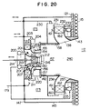
- Fig. 20 is a view showing the burner shown in Fig. 15 in detail.
- Referring to Figs. 1 and 2, a burner comprises a cylindrical
diffusion flame burner 6 disposed in a central portion and a plurality of premixtureflame burner apparatus 1000 disposed around thediffusion flame burner 6. Thediffusion flame burner 6 has a fuel nozzle 11 disposed in a center thereof andair nozzles 10 disposed around the fuel nozzle 11. A multiplicity ofheat transfer tubes 117 are disposed adjacent to afurnace wall 999. Inside a burner throat, there are provided anignitor 13 andwater pipes 12 for prevention of burning loss of the burner. In Fig. 1, the premixtureflame burner apparatus 1000 comprises sixrectangular burners 1000a through 1000f. Each of these burners comprises apremixture injection nozzle 2, anair damper 7, arectifier plate 3, anair supply pipe 5, and afuel nozzle 4. Thefuel nozzle 4 has a plurality of openings, through which the fuel is dispersed and fed into the air flow. The zone downstream of thefuel nozzle 4 is the mixing zone. Therectifier plate 3, which is a honeycomb-structured resistor, has a rectifying function to form a flow of a uniform speed distribution and also has a function to prevent a backfire of the premixture flame since the outlet velocity is increased as the passage cross section is reduced here. A strip-shapedflame holder 1 is disposed near the outlet of thenozzle 2 to extend perpendicular to a direction of the mainstream of the mixture. The lengths of the sides of theflame holder 1 are shorter than the corresponding sides of the nozzle. The reason is that if the longitudinal length of the side of the flame holder is longer than that of the corresponding side of the nozzle, a part of the mixture flow is bent and injected at right angles to the mainstream, thereby deteriorating the stability of the flame. - When the boiler is started up, the
diffusion combustion burner 6 is used, and as the boiler load is increased, the mixture of fuel and air is injected from the premixtureflame bruner apparatus 1000. The premixture flame burner apparatus, in this embodiment, injects firstly the mixture from one of the sixburners 1000a - 1000f, and as the load increases, the mixture is injected from the other burners successively. Thediffusion flame burner 6 is used to stabilize the premixture flame. However, under the condition that the premixture flame is formed stably, no fuel and air is injected from thediffusion flame burner 6. - As will be understood from Fig. 2, in the
diffusion flame burner 6, a fuel nozzle 11 is installed coaxially with theburner 6 and anair nozzle 10 is disposed to surround the fuel nozzle 11. Aflame holder 9 is provided above an upper end of the fuel nozzle 11 to stabilize the diffusion flame. Aswirl flow generator 8 installed at theair nozzle 10 prometes mixing of fuel and air, thereby shortening the diffusion flame. The premixture flame burner includes thefuel nozzle 4 having a plurality of openings, provided upstream of thepremixture injection nozzle 2. The gaseous fuel supplied from thefuel nozzle 4 and air supplied from theair supply pipe 5 are mixed uniformly before the mixture is injected from thepremixture injection nozzle 2. The quantity of combustion air is controlled by theair damper 7. Therectifier plate 3 rectifies the flow of air and serves as a flame arrester to prevent a backfire of the premixture flame. Theflame holder 1 in a strip form is provided downstream of thepremixture injection nozzle 2 to stabilze the premixture flame. Theflame holder 1 have an area smaller than thepremixture injection nozzle 2. - Fig. 3 shows a boilder in which the burner of Fig. 1 is installed. The boiler is a natural circulation type water pipe boiler. Water stored in a
water drum 131 is introduced throughheat transfer pipes 117 into asteam drum 128. In thesteam drum 128, water is separated from steam and returned to thewater drum 131, while the steam is accumulated in aseam reservoir 129. As will be mentioned in the description of another embodiment, it is desirable that the premixture flow should spread over a space greater than a burner diameter, and that the nozzle injection outlets of the premixture burner apparatus are located flush with the furnace wall. The combustion gas is discharged through anexhaust gas duct 114 to the outside of the boilder. In this process, the unburnt gas is burnt by acombustor 126. - The combustion gas flows in a direction opposite to the flow direction of the premixture in the
exhaust gas duct 114, and is preheated by afirst air preheater 123 and asecond air preheater 124 at the front and the rear stages of theunburnt gas combustor 126, respectively. - According to the invention, the generation of NOx does not depend on the combustion load and the flame can be shortened. Therefore it becomes possible to rise a heat load of the furnace above 2,000,000 kcal/m³h (2,326 KW/m³). The flame length can be normally shortened to less than 50 cm. It is enough that the depth of the furnace is 1 m. The boiler according to this invention can increase a capacity thereof by only expanding the furnace in the longitudinal direction of the water drum and the steam drum to increase the heat transfer area. This can be attained by use of a premixture flame burner with a flame holder because in this case, even if the burner capacity is increased, the flame length hardly changes. Needless to say, by increasing the number of premixture nozzles, the boiler capacity can be increased. Referring with Fig. 4, the fuel supply rate on the axis of ordinate represents in percentage the ratio of the fuel used by the respective nozzle to the fuel used by the boiler when the boiler load is 100%. Up to 20% boiler load, only the diffusion flame burner is used, and when the load reaches 20%, the nozzle A (the
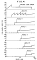
premixture burner 1000a with a flame holder) feeds fuel and air. At this time, in order to prevent the flame going back into the nozzle, namely to prevent a backfire, it is safe to keep the injection velocity of the premixture at 20 m/s or more. Therefore, in order to inject the premixture of an air ratio of 1.1 at the velocity of 20 m/s from the nozzle A, the quantities of fuel and air from the diffusion flame burner corresponding to this air ratio are decreased and the quantities of fuel and air corresponding to such decreased quantities are injected from the nozzle A. Then, until the boiler load reaches 30%, the quantities of fuel and air injected from the nozzle A are increased. When 30% is reached, a premixture of an air ratio of 1.1 is injected from the nozzle B (thepremixture burner 1000b with a flame holder) at 20 m/s. The premixture injected from the nozzle A is decreased by a quantity of the premixture corresponding to the quantity of the premixture injected from the nozzle B. When the boiler load reaches 40%, 50%, 60% and 70%, the similar operation is repeated and the premixture is injected from the nozzle C (thepremixture flame burner 1000c with a flame holder), the nozzle D (thepremixture flame burner 1000d with a flame holder), the nozzle E (the premixture flame burner 1000e with a flame holder), and the nozzle F (the premixture flame burner 1000f) in that order. When the load is changed from 70% to 90%, the quantities of the premixture fed from the nozzles A, B, C and D are changed accordingly. When the load reaches 90%, the use of the diffusion flame burner is stopped, and the premixture including the quantities of fuel and air corresponding to those injected from the diffusion flame burner is fed from the nozzles E and F. When the load changes from 90% to 100%, the quantities of the premixture fed from the nozzles A, B, C, D, E and F are changed accordingly. - Fig. 5 shows the result of study into the blowout limit of the premixture flame stabilized by a flame holder disposed downstream of the premixture injection outlets. The axis of abscissa represents the excess air ratio of the premixture and the axis of ordinate represents the injection velocity of the premixture. In Fig. 5, the white dots indicate the stable combustion of the premixture flame and the black dots indicate that the premixture flame becomes unsatable and blows out. It will be understood that the stable combustion range of the premixture flame stabilized by the flame holder becomes narrower as the excess air ratio increases. As is apparent from the figure, when operating a boiler, by setting the excess air ratio of the premixture in a range of 1.0 to 1.3, the stable combustion of the premixture can be obtained at the injection velocity of about 50 m/s. According to this result, in the operating method of the boiler shown in Fig. 3, when the premixture injection velocity is set at 50 m/s at 25% fuel supply rate to the nozzle A, if the boiler load is reduced by decreasing the premixture injection velocity with keeping the excess air ratio of the premixture constant, the premixture injection velocity at the boiler load of 10% becoms 20 m/s, and therefore the premixture flame can burn stably without backfire.
- Fig. 6 shows the effects of the flame holder on the reduction of NOx of the stabilized premixture flame. The axis of abscissa represents the excess air ratio of the premixture and the axis of ordinate presents the concentration of NOx from the boiler. Fig. 7A shows a burner according to the invention with a flame holder for stabilizing the premixture flame. Near the peripheral edge of the
flame holder 1 disposed downstream of apremixture injection outlet 21, there is formed swirls of the premixture as indicated by the arrows, and then an ignition is occurred in this area. After the ignition, as the injection quantity of the premixture is increased, high-temperature combustion products circulate inside and outside thepremixture flame 99 as indicated by the arrows. As a result, since the energy can be supplied continuously to the premixture, the premixture flame is formed stably. Fig. 7B shows a burner in which the premixture flame is stabilized by means of a pilot flame. The premixture of an excess air ratio of about 1.0 is supplied to thepremixture supply pipe 22 to form astable pilot flame 300 at an annular nozzle provided around the outer periphery of the cylindricalpremixture injection outlet 23. The premixture from the premixture inejctionoutlet 23 receives energy from thepilot flame 300, so that thepremixture flame 99 is formed as shown in Fig. 7B. In Fig. 6, the NOx concentration is compared between the above-mentioned two kinds of premixed flames. At an excess air ratio of 1.05, the premixture flame with the pilot flame generates NOx of about 800 ppm, while the premixture flame with the flame holder generates NOx of no more than 25 ppm. In case that the excess air ratio of the premixture is in a range of 1.0 to 1.3, the concentration of NOx from the premixture flame with a flame holder is about one third of the NOx concentration from the premixture flame with the pilot flame. The reason why the premixture flame with a flame holder can reduce NOx is that the combustion products such as carbon dioxide gas circulate inside and outside the flame as indicated by the arrows in Fig. 7A and flow into the flame portion where combustion is in progress to reduce an oxygen partial pressure which governs the NOx generation, thereby decreasing the concentration of NOx generated. The numerals given beside the white dots in Fig. 6 represent combustion loads in units of 10⁴ Kcal/m³h (11,6 KW/m³). As can be seen from Fig. 6, even if the combustion load changes between 66 x 10⁴ Kcal/m³h and 267 x 10⁴ Kcal/m³h (66x11.6 and 267x11.6 KW/m³), the NOx concentration hardly changes. Therefore, by using the premixture combustion method relating to the invention, a high-load and low-NOx boiler can be realized. - Fig. 8 shows the effect of the ratio of a combustion inner diameter D3 to the premixture nozzle inner diameter D2 on the concentration of NOx generated from the premixture flame of the premixture flame burner with a flame holder. As will be apparent from the figure, in case that D3/D2 is smaller than 4, the NOx concentration is high. This is considered as follows. As the combustor inner diameter D3 becomes small, it becomes difficult for the combustion products to circulate outside the flame, which allows the oxygen partial presssure to increase, thus increasing the NOx concentration.
- Figs. 9A and 9B show a modification of the burner apparatus for a low-NOx boiler of Fig. 1. The buffer apparatus comprises a cylindrical diffusion flame burner with a flame holder disposed in the center, and an annular premixture flame burner with a flame holder disposed around the diffusion flame burner. The premixture flame burner is composed of four
nozzles injection outlet 21 and amixture rectifier 3 located between the mixing zone and theinjection outlet 21. The fuel is diffused through the fuel nozzle having a plurality of outlets into the air flow to be mixed together. Therectifier 3 is a flow-passage resistor of honeycomb structure. At each nozzle outlet a strip-shapedflame holder 1 is so disposed as to extend perpendicular to the direction of the flow of mixture. The sides of the flame holder are shorter than the corresponding sides of the nozzle. - When the boiler is started up, the diffusion combustion burner disposed in the center of the burner is used firstly, and as the boiler load is increased, the fuel-air mixture is injected from the premixture burner with the flame holder. In connection with an operation of the premixture combustion burner, in this embodiment, the mixture is at first injected from one of the four nozzles, and as the load increases, the premixture is injected from the other nozzles in succession. The diffusion flame burner is used to stabilize the premixture flame. However, under the condition that the premixture flame is formed stably, the injection of fuel and air from the diffusion flame burner is stopped.
- Fig. 10 shows a relation between the boiler load equipped with the low-NOx burner of Figs. 9A and 9B and the fuel supply rate from each nozzle. The fuel supply rate on the axis of ordinate represents the ratio of the fuel used by each nozzle to the fuel used by the boiler when the boiler load is 100% in percentage. Up to a boiler load of 20%, only the diffusion flame burner is used, and when the load reaches 20%, fuel and air are fed through the nozzle A, an arbitrary one of the four nozzles. At this time, in order to prevent the flame from withdrawing back into the nozzle, i.e. to prevent a backfire, it is safe to maintain the injection velocity of the premixture at 20 m/s or higher. Therefore, in order to inject the premixture of an air ratio of 1.1 from the nozzle A at the velocity of 20 m/s, the fuel and air injected from the diffusion flame burner is reduced by quantities thereof corresponding to those injected from the nozzle A, and fuel and air thus reduced are injected from the nozzle A. The fuel and the air injected from the nozzle A are increased until the boiler load reaches 30%, and when 30% is reached, the premixture of air ratio of 1.1 is injected at the velocity of 20 m/s from the nozzle B, another arbitrary one of the remaining three nozzles. At this time, the premixture injected from the nozzle A is reduced by a quantity of the premixture corresponding to that of the premixture injected from the nozzle B. When the load reaches 50% and 70%, the similar operation is repeated. Namely the premixture is injected from the nozzle C, an arbitrary one of the remaining two nozzles when the load is 50% and the premixture is injected from the nozzle D, the last one of the four nozzles when the load is 70%. When the load reaches 90%, the use of the diffusion flame burner is stopped, and the nozzles A and B inject the quantity of the premixture corresponding to the quantities of fuel and air which have been injected from the diffusion flame burner. When the load is changed between 90% and 100%, the quantities of the premixture injected from the nozzles C and D are changed accordingly.
- Fig. 11 is another modification of the low-NOx burner of Fig. 1. This embodiment features the use of
hemisphere Venturi portions 27 as rectifying means to form a uniform premixture of gaseous fuel and combustion air. The consturction except for theVenturi portions 27 is the same as in Figs. 9A and 9B. - Figs. 12a and 12B show the construction of a burner apparatus for a low-NOx boiler, having a plurality of cylindrical premixture nozzles. The burner apparatus comprises a first cylidnrical
diffusion flame burner 6 for ignition disposed at the center thereof, and a plurality ofpremixture flame burners 1000 each having a flame holder, disposed to surround thediffusion flame burner 6. Each of thepremixture flame burners 1000 has a second cylindricaldiffusion flame burner 600 for ignition disposed coaxially with theinjection outlet 32 of the premixture nozzle. In the firstdiffusion flame burner 6, afuel nozzle 35 is provided coaxially with an axis of the burner, and anair nozzle 36 is disposed around thefuel nozzle 35. Theair nozzle 36 has aswirl flow generator 37 mounted therein so as to control the swirl strength of combustion air. Thepremixture flame burner 1000 has afuel nozzle 39 for premixture combustion disposed upstream of thepremixture injection outlet 32. The gaseous fuel from thefuel nozzle 39 and the combustion air from anair supply pipe 40 are mixed to form a uniform premixture through aVenturi portion 41. The seconddiffusion flame burner 600 is disposed coaxially with thepremixture injection outlet 32, and afuel nozzle 45 is disposed coaxially with thediffusion flame burner 600. Anair nozzle 46 is disposed to surround thefuel nozzle 45. Theair nozzle 46 is provided with a swirl flow generator 44 which serves to shorten the diffusion flame of the second diffusion flame burner. When it is difficult that the first diffusion flame burner ignites the premixture from thepremixture injection outlet 32, the second diffusion flame burner ignites the whole of the premixture. The above-mentioned two kinds of diffusion flames are used to ignite the premixture when the boiler load is changed. At an upper end of theair nozzle 46, there is provided aflame holder 31. Theflame hodler 31 causes a circulating flow of the premixture to near the peripheral edge of the flame holder, thereby improving the stability of the premixed flame. Furthermore, theflame holder 31 causes combustion products to be circulated inside and outside the flame, so that NOx can be reduced. - Figs. 13A and 13B show a modification of the burner for a low-NOx boiler, provided with a plurality of cylindrical premixture injection outlets. The burner comprises a first cylindrical
diffusion flame burner 6 for ignition and a plurality ofpremixture flame burners 1000 disposed surrounding thediffusion flame burner 6. Theburner 1000 hasfuel nozzle 60 for the second diffusion flame provided coaxially with the axis of thepremixture outlet 48. The firstdiffusion flame burner 6 has afuel nozzle 49 provided coaxially therewith and anair nozzle 50 surrounding thefuel nozzle 49. Theair nozzle 50 has aswirl flow generator 54 installed therein to control the swirl strength of the combustion air. In thepremixture flame burner 1000, afuel nozzle 55 for premixture combustion is disposed upstream of thepremixture injection outlet 48. The fuel from thefuel nozzle 55 and the combustion air from theair supply pipe 56 are mixed to form a uniform premixture by theswirl flow generator 57. Between theswirl flow generator 57 and thepremixture injection outlet 48, there is provided rectifying means 59 which serves to form a uniform speed distribution of the premixture in the radial direction of theoutlet 48. Afuel nozzle 60 for the second diffusion flame is disposed coaxially with theoutlet 48. When it is difficult that the first diffusion ignites the premixture from theoutlet 48, the second diffusion flame is formed to ignite the whole of the premixture. The above-mentioned two types of diffusion flames are used to ignite the premixture when the boiler load is changed. At a position downstream of thepremixture injection outlet 48, there is provided aflame holder 47, which causes a circulating flow of the premixture near the peripheral edge of the flame holder, thereby improving the stability of the premixture flame. Furthermore, theflame holder 47 causes combustion products to be circulated inside and outside the flame, so that NOx can be reduced. - With reference to Figs. 14A and 14B, the following description will now be made to the effect obtained due to the rectification of the premixture of gaseous fuel and air by the
rectifier 59 shown in Figs. 13A and 13B. Figs. 14A shows the pressure, distribution along the radial direction of thepremixture injection outlet 48 measured by the Pitot tube, while Fig. 14B shows the speed distribution of the premixture along the radial direction of theoutlet 48. A flared peripheral edge of aflame holder 47 is located at 20 mm in radial direction from the axis of theholder 47, while a base peripheral edge of theholder 47 is located at 10 mm in the radial direction. A peripheral edge of thepremixture injection outlet 48 is lcoated at about 33 mm in the radial direction from the axis of theholder 47. In Figs. 14A and 14B, solid lines indicated byreference numerals 61 and 63 represent the pressure and the speed distributions when no rectifying means is provided, and broken lines indicated byreference numerals holder 47 due to the action of theswirl flow generator 57. In Fig. 14B, when no rectifying means 59 is provided (the solid line 63), the premixture accumulates near the outer periphery of theoutlet 48 due to a centrifugal force caused by theswirl flow generator 57, so that the premixture is not accumulated above theflame holder 47. Consequently, the premixture flame is located at the outer periphery of theoutlet 48. The high-temperature exhaust gas caused by the premixture flame is drawn into the negative pressure zone extending around the center portion of theoutlet 48, so that a flame is formed from within theoutlet 48. Raised is a problem that theflame holder 47 deteriorates as it it heated from the upstream side thereof. When a honeycomb is installed as rectifying means 59, a negative pressure zone is hardly generated as indicated by thebroken line 62 of Fig. 14A. The premixture is distributed above theflame holder 47, as indicated by thebroken line 64 of Fig. 14B. As a result, a circulating flow as shown in Fig. 7A is formed near the flared peripheral edge of theflame holder 47, whereby the premixture flame is stabilized. - With reference to Figs. 15 through 20, the following description will be made to a boiler having a primary combustion chamber provided in the burner, in which combustion is executed with a low air ratio of 1 or below, whereby obtaining a high load and low NOx combustion.
- Fig. 15 corresponds to a horizontal sectional view of the boiler of Fig. 3.
- A
furnace 112 comprises a plurality of radiant heat transfer pipes 115a arranged mutually adjacent on the upsteam side (left side in Fig. 15) to form a furnace front wall 180a, radiantheat transfer pipes 115b and 115c arranged to form walls extending from the opposite ends of the furnace front wall 180a and extending perpendicular thereto towards the downstream side (right side in Fig. 15) so that a combustion chamber is defined therebetween,steam generating pipes heat transfer pipes 115b and 115c, and steamheat transfer pipes 117 located between walls of thestream generating pipes heat transfer pipes 115b and 115c of thefurnace 112, there is provided asteam drum 128 extending from the upstream to the downstream of thefurnace 112. At the bottom center position, there is provided awater drum 131 in parallel with thesteam drum 128. The radiantheat transfer pipes 115a, 115b and 115c are connected at their lower ends with thewater drum 131 and at their upper ends with the water phase in thesteam drum 128. In the center of the furnace bottom between the walls of thesteam generating pipes steam distribution pipe 132 on the extension of the axis of thewater drum 131. At the upper center position of the furnace above thesteam distribution pipe 132, there is asteam reservoir 129 in parallel with the axis of thesteam drum 128. Thesteam reservoir 129 extends into thesteam drum 128 on the upstream side and located under the surface of the water in thesteam drum 128. Thesteam generating pipes steam distribution pipes 132. Each of the radiantheat transfer pipes 115b and 115c and thesteam generating pipes plates 169. The adjacentflat plates 169 are partially overlapping each other to constitute thefurnace side walls - On the downstream portion of the
furnace 112, there isheating passages 170a and 170b separating horizontally to the left and right sides. Theheating passages 170a and 170b are defined by a radiantheat transfer pipe 115d, radiantheat transfer pipes heat transfer pipes 117,steam generating pipes downcast pipes 120a and 120b, andsteam generating pipes pipe 115d is located spaced from thesteam generating pipes furnace side walls pipe 115d also constitutes a heating-passagerear wall 180d parallel with the furnace front wall 180a and wider than the furnace front wall 180a. The radiantheat transfer pipes rear wall 180d towards the upstream side and constituting part of the heating-passage side walls furnace side walls heat transfer pipes 117 are, on the extreme downstream side, disposed between thefurnace side walls steam generating pipes heat transfer pipes passage side walls downcase pipes 120a and 120b are disposed between thesteam generating pipes boiler side walls steam generating pipes furnace side wall heat transfer pipes water drum 131 and at their upper ends to the water phase in thesteam drum 128. Thesteam generating pipes steam generating pipes steam distributing pipe 132, and thesteam generating pipes water reservoir 133. Thereservoir 133 is arranged on the lower furnace side of the heatingpassage side walls side walls steam generating pipes boiler side walls steam generating pipes furnace side walls steam generating pipes steam generating pipes steam distributing pipe 132. The steamheat transfer pipes 117 are connected at their upper ends to thesteam reservoir 129 and at their lower ends to thesteam distributing pipe 132. In theheating passages 170a and 170b, there is superheaters 118 forming a single bent pipe comprising a plurality of pipes interconnected each other. Thesuperheaters 118 are connected at one ends thereof to the steam phase of thesteam drum 128 throughsteam pipes 130, and at the other ends thereof to steam-applied equipment, not shown, such as a steam turbine and a chemical plant. -
Downcast pipes 120a and 120b are provided adjacent to the heating-passage side walls downcast pipes 120a and 120b constituteflue side wals 180g and 180h parallel with the furnacewall side walls Downcast pipes 120c and 120d are arranged in the opposite extensions of the furnace front walls 180a to constitute fluefront wall 180j and 180k. - A
flue 114a is defined by a fluetop plate 134 provided above thefurnace side wall 180b, the flue side wall 180g, the flue front wall 180j, and thesteam generating pipes flue bottom plate 135 provided below thesteam generating pipe 116a. Aflue 114b is defined by a fluetop plate 134 provided above thefurnace side wall 180c, theflue side wall 180h, the fluefront wall 180k, and thesteam generating pipes flue bottom plate 35 provided below thesteam generating pipe 116b. - In each of the
flues heat transfer pipes 119 are provided, for example, in 20 rows, each having fivepipes 119. The convectionheat transfer pipes 119 are connected at their upper ends to the water phase of thesteam drum 128, and at their lower ends to thewater drum 131. The downcast pipes 120a and 120c communicate at their lower ends with thewater drum 131 and at their upper ends with the water phase of thesteam drum 128. Return pipes, not shown, are provided, which communicate between the bottom part of thesteam reservoir 129 within thesteam drum 128, and thewater reservoirs 133. The return pipes are installed such that they are inclined from thesteam reservoir 129 to thewater reservoirs 133 to ensure that there is no air pocket in the midway thereof. - Above the
flues upper flues steam drum 128 and in parallel with thesteam drum 128. Theflues upper flue top plate 134. Theupper flues upper flue 114d. Combustion gas rises from theflue 114b through the above mentioned openings, and flows through theupper flue 114d in the direction opposite to the combustion gas flow in theflue 114b. Theupper flue 114d includes asecond air preheater 124 provided downstream of the openings, anunburnt gas combustor 126 provided downstrem of thesecond air preheater 124, and afirst air preheater 123 provided downstream of theunburnt gas combustor 126. Thefirst air preheater 123 and thesecond air preheater 124 are almost identical in constuction. Each preheater comprisestube plates 171 provided at the opposite ends in the direction of the combustion gas flow, a plurality of round pipes constituting a smoke duct communicating between thetube plates 171, and baffleplates 172, the number of which is odd, provided between the tube plates 171 (for example, threeplates 172 for the first air preheater and oneplate 172 for the second air preheater). These smoke ducts serve as means for rectifying the flow of the exhaust gas. - The
unburnt gas combustor 126 oxidize carbon monoxide, which is the unburnt gas in the exhaust gas, to be carbon dioxide. Theunburnt gas combustor 126 was made by catalyst for accelerating reaction in a plate form and disposed almost in parallel with the flow of the exhaust gas in the passage of the exhaust gas. Used is the catalyst with an active temperature in the range of 300° to 1000°C. The catalyst need not be in a plate form but may be in a grill form. It is also possible to use spheroidal bodies about 3 mm in diameter as carriers of catalyst and make spheroidal catalyst. The spheroidal catalyst may be filled in the exhaust gas passage. - On that side of the
upper flue 114d which is closer to thesteam drum 128, anair supply duct 122b is arranged in parallel with theupper flue 114d. Theupper flue 114d and theair supply duct 122b are adjacent to each other through the intermediary of the upperflue side plate 114f. The baffle plates of thefirst air preheater 123, which include the one adjacent to thetube plate 171, are alternately extended into the inside of theair supply duct 122b, thereby interrupting the passage of theair supply duct 122b. At the position in theair supply duct 122b adjacent to thebaffle plate 172 in thesecond air preheater 124, there is provided aheating control valve 125 comprising a flat plate supported by the top surface and the bottom surface of theair supply duct 122b and formed integrally with a rotatable post. Thisheating control valve 125 controls the quantity of air flowing into the second air preheater. The angle between the flat plate and the longitudinal direction of theair supply duct 122b can be controlled to change the passage cross section of theduct 122b. The upperflue side plate 114f is not provided at the adjoining part of the first and second air preheaters, and theair supply duct 122b. Therefore, gas can flow freely between them. One end portion of theair supply duct 122b close to a fluefront wall 180k is extended to the opposite side of theflue 114b of the fluefront wall 180k, and communicates with awindow box 173 formed around the periphery of aburner throat 143 provided in the furnace front wall 180a outside the furnace. The other end portion of theduct 122b communicates to a blower apparatus (not shown). - The
window box 173 is provided coaxially with theburner throat 143, and is surrounded by a cylindrical burnerouter wall 145 larger in diameter than the burner throat, and aburner side wall 147 forming an end face of the cylinder. Aburner 111 is provided at the center of thewindow box 173. - The
burner 111 includes aprimary combustion chamber 157 at the center thereof. Theprimary combustion chamber 157 comprises amain mixture passage 212 located on the upstream side and serving as the main nozzle for forming a main combustion flame of an air ratio of 1 or less, anannular stabilizer plate 155 having pilot flame holes 156 each forming a pilot flame located to surround themain premixture passage 212, a primary combustionchamber side wall 217 disposed at the outer periphery of thestabilizer plate 155 to constitute an upstream side wall of theprimary combustion chamber 157, a wall surface formed ofwater cooling pipes 158 disposed at the outer periphery of the primary combustionchamber side wall 217, and a cylindrical primary combustion chamberouter wall 142 provided contiguous at one end thereof on the upstream side to the wall surface formed ofwater cooling pipes 158 and loosely extending at the other end thereof into theburner throat 143 and facing the furnace. - A
secondary combustion chamber 240 is formed on the downstream side of theprimary combustion chamber 157. Thesecondary combustion chamber 240 is continuous on the upstream side thereof to theprimary combustion chamber 157, and opened on the downstream side thereof to thefurnace 112. A wall of thesecondary combustion chamber 240, which connects an axial end portion thereof opened to theprimary combustion chamber 157 and the other axial end portion thereof opened to thefurnace 112, is provided with theburner throat 143 and an annular auxiliary mixture passage 238 defined between anozzle 237 forming an inner surface of theburner throat 143 and a nozzle 236 having the end portion of theprimary combustion chamber 142 closer to the furnace. The burner thoat 143 and the auxiliary mixed gas passage 238 are provided such that the cross section of thesecondary combustion chamber 240, which is perpendicular to the axis of the burner, increases towards the furnace. - The auxiliary mixture passage 238 is opened at one end thereof to the
secondary combustion chamber 240. The other end of the passage 238 communicates withair supply ducts damper 232 and thewindow box 173. At the outer peripheries of thenozzles 236 and 237,discs type swirl vanes 162 are mounted in an annular space defined between thediscs support post 161. Thepost 161 is mounted with its axis parallel with the generating line of a cylinder constituting theprimary combustion chamber 142, and the opposite ends of thepots 161 are rotatably born in bearing holes formed in thediscs rotary vane 162, there are formed a plurality of fuel injection holes 251. The holes 251 are connected to a fuel reservoir to which gaseous fuel is supplied, through a gas reservoir 252 in thevane 162, and a supply pipe passing through the central part of either one of the support posts 161 on the furnace side and the side closer to theburner side wall 147 and also through a communicatingpipe 234. Thedamper 232 is attached integrally to the upstream side ends of thediscs damper 232 is amovable damper 231 formed integrally with acontrol rod 230 passing through the burner side wall. Each of thedamper 232 and themovable damper 231 has a plurality of circular apertures. As themovable damper 231 is moved by thecontrol rod 230 in the direction of the generating line of the primary combustion chamberouter wall 142, the area of the apertures projected in the downstream direction is controlled. When the apertures of themovable damper 231 coincide with the apertures of thedamper 232, the area of the apertures is maximum, so that the air flow rate into the auxiliary mixture passage is maximum. Conversely, when thedampers movable damper 231 do not coincide with the apertures of thedamper 232, the area of the aperture is minimum, so that the air flow rate into the auxiliary mixture passage is minimum. Description has been made to themovable damper 231 which has a plurality of apertures, but it is also possible to achieve the same object by use of amovable damper 231 which is made of a disc plate without apertures. - The main mixture passage for forming a main flame is provided on the inner periphery of the
stabilizer plate 155 for forming a pilot flame. The main mixture passage is an annular passage defined by a primary throat 210 and a premixture throat 140 provided to surround the outer periphery of the primary throat 210. The upstream side of the primary throat 210 is connected to anozzle 208 having an arc cross section. The upstream side of the premixture throat 140 is connected to anozzle 209 having an arc cross section. The end face of the upstream side of thenozzle 208 is connected to the burner side wall, while the end face of the upstream side of thenozzle 209 is connected to a premixture side wall 211 provided on a side of theburner side wall 147 which is closer to the furnace. A plurality of resistortype swirl vanes 206 are mounted in an annular space defined by theburner side wall 147 and the premixture side wall 211. Each vane is provided integrally with asupport post 207. Thepost 207 is mounted with its axis parallel with the generating line of a cylinder constituting the primary combustion chamberouter wall 142, and the opposite ends of thepost 207 are rotatably born in bearing holes formed in theburner side wall 147 and the premixture side wall 211. Thepost 207 is mounted to thevane 206 near the downstream side thereof. Therefore, even if the inclination angle of thevane 206 is increased to rise the swirl strength, it does not occur that the adjacent vanes contact one another and the opening area of the outlet of the vane is decreased. The upstream side end face of the premixture side wall 211 is connected to one end of adamper 205 disposed concentrically with the primary combustion chamberouter wall 142. The other end of thedamper 205 is connected to theburner side wall 147. Around the outer periphery of thedamper 205, there is provided amovable damper 204 formed integrally with acontrol rod 203. Thedamper 205 and themovable damper 204 have the construction and operation similar to those of thedamper 231 and themovable damper 232. - On the downstream side of the vanes, there are a plurality of
fuel pipes 201 passing through thenozzle 208. On a side of each fuel pipe which is closer to the furnace, there is provided aninjection hole 202. Theinjection hole 202 is opened at downstream side thereof to the main mixture passage. Theinjection hole 202 is connected at upstream side thereof to afuel pipe 179 through thefuel pipes 201 and afuel reservoir 200 connected to the plurality offuel pipes 201. - The primary throat 210 holds a
cylinder 215 at the inner periphery thereof. A flowspeed control valve 216 is connected to the furnace side of thecylinder 215. Thevalve 216, at the upstream side thereof, has a diameter equal to the diameter of thecylinder 215 and the diameter of thevalue 216 increases towards the furnace. Thevalve 216 is born to be movable in the direction of the generating line of the primary combustion chamberouter wall 142 by means of the primary throat 210, thecylinder 215, and ablind plate 213 attached to thenozzle 208 and having in the center thereof a guide for a flowspeed control rod 214. The flowspeed control rod 214 is connected integrally with thecylinder 215 and controls the flowvelocity control valve 216. When the valve 16 is moved to the upstream side (the state as indicated by the solid line in Fig. 20), the passage area of themain mixture passage 212 facing theprimary combustion chamber 157 is minimized. The flowvelocity control valve 216, when moved to the downstream side (the state indicated by the broken line in Fig. 20), maximizes the passage area of themain mixture passage 212 facing theprimary combustion chamber 157. - The flow
speed control valve 216 operates according to the quantity of mixture supplied to themain premixture passage 212 to control the passage area of the main premixture passage, which is closer to theprimary combustion chamber 157. For example, it is possible to make the speed of the premixture injected from themain premixture passage 212 generally constant, irrespective of the supply flow rate of the premixture. Therefore, it is possible to prevent the flame from withdrawing into the main mixture passage under a combustion condition with low load and reduced supply of premixture. The volume flow rate of air varies according to the preheating temperature. If the flowspeed control valve 216 operates so that the cubic expansion can be compensated by measurement of a preheating temperature of air, the outlet speed of the main mixture can be maintained constant irrespective of the preheating temperature. Also, by attaching a flame holder to the flowspeed control valve 216, the main combustion flame can be made more stable. - By moving the
control rods movable damper 204 and thedamper 231 is changed, so that the area of apertures obtained by mutual overlapping of themovable damper 204 and thedamper 231 is changed accordingly. More specifically, as themovable damper 204 changes its position, it changes the area of the apertures, thereby controlling the quantity of air flowing into themain mixture passage 212 or the auxiliary mixture passage 238. The pressure loss in the vanes which occurs when the inclination angle of thevane - The fuel supplied from the
fuel reseroir 233 flows through the communicatingpipe 234, thesupport post 161 and the gas reservoir 252 held within thevane 162, and injected from a plurality of fuel injection holes 251 provided at the downstream side end face of thevane 162. The injected fuel is mixed with air fed to the auxiliary mixture passage 238, thus forming premixture, which becomes an auxiliary combustion flame. The method of injecting gaseous fuel from the fuel injection holes 251 of thevane 162 can shorten the time necessary for mixing of the air and the gaseous fuel, as compared with the method of mixing the gaseous fuel in the air, which fuel is injected from thefuel pipe 201 extending into the passage. Therefore, the auxiliary mixture passage can be shorter than the main mixture passage. This is because a swirl 254 formed after the swirl vane has a greater intensity of turbulence than that of the downstream side of thefuel pipe 202. The injected gaseous fuel is drawn into the swirl 254 and then mixed completely with the air by small swirls generated by the swirl 254. the mixing of gaseous fuel and air is further promoted in case that the intensity of turbulence is increased by providing protrusions on the surfaces of the vane. Furthermore, according to the method of injecting gaseous fuel from the vane, since no obtacles is provided on the downstream side of the vane, the swirl flow formed by the vane is not damped by obstacles. - Fuel is separately supplied to form a main combustion flame and an auxiliary combustion flame. When a combustion load is small and the fuel supply rate is low, the boiler cuts off a supply of fuel to the auxiliary mixture passage.
- The
stabilizer plate 155 injects premixture of an air ratio of 1 or more preferably 1.0 to 1.5 at a few meters per second, preferably 1 to 3 m/s into theprimary combustion chamber 157 to form a pilot flame of the premixture. The main combustion mixture passage injects premixture of an air ratio of 1 or less, preferably 0.5 to 0.9 at 20 to 50 m/s in a swirl flow manner into theprimary combustion chamber 157, which is ignited by the pilot flame to form the main combustion flame. The auxiliary combustion mixture pasage injects premixture of an air ratio of 1 or more, preferably 1.0 to 1.5 at the 20 to 20 m/s in a swirl flow manner into thesecondary combustion chamber 240, which is ignited by the main combustion flame to form the auxiliary combustion flame. Since the air ratio of the premixture forming the main combustion flame is 1 or less, the maximum temperature of the flame is lower than the conventional diffusion flame, so that the production of thermal NOx is restrained. At the same time, the thermal NOx produced by combustion is subjected to vapor-phase reduction by intermediate products of the gaseous fuel and reduced to nitrogen. The intermediate products by the main combustion flame vapor-phase reduce the thermal NOx produced by the auxiliary combustion flame into nitrogen. The vapor-phase reduction of the NOx produced by the auxiliary combustion flame due to the main combustion flame is promoted by providing the primary combustion chamber with an angled portion so as to let the mixture from the auxiliary mixture passage smash into the main combustion flame. Since the cross section of the secondary combustion chamber in the flow direction increases towards the furnace, there is no rise in speed in the secondary combustion chamber where the main combustion flame and the auxiliary combustion flame are formed. - With regard to the pilot flame, description has been made to a case where it is formed by premixture. The object of the pilot flame lies in igniting the main combustion mixture to form a main combustion flame. Therefore, the method of forming a flame by injecting a small quantity of fuel into the primary combustion chamber and air into the fuel from around thereof, that is to say, the method of forming a pilot flame by the diffusion flame does not deviate from the object of the present invention.
- In this embodiment, description has been made to the burner construction wherein the gaseous fuel is divided into three portions, which are separately supplied to form a pilot flame, a main combustion frame and an auxiliary combustion flame. And the ignition is caused to take place successively by the flames in the above-mentioned order. The gaseous fuel may be divided into more than three portions, if possible.
- The radiant
heat transfer pipe 115b is abutted onto thefurnace 112 and theflue 114a, while the radiant heat transfer pipe 115c is abutted onto thefurnace 112 and theflue 114b. The surface temperature of the sides of the radiantheat transfer pipes 115b and 115c closer to the flues becomes substantially equal to the exhaust gas temperature in the flues. Therefore, the heat quantity escaping to the outside from the sides of the radiant heat transfer pipes which are apart from the furnace is reduced compared with the conventional techniques in which the sides of the radiant heat transfer pipes which are apart from the furnace are covered by heat insulators. Thus, in the present embodiment, the thermal efficiency of the boiler is improved. - Since the convection
heat transfer pipes 119 are disposed in a plural number in the direction not in parallel with the flow direction of the combustion gas, the flow near the surface of the convectionheat transfer pipes 119 is kept in a turbulent state, whereby the heat transfer rate is raised. Also, it has become possible to secure a heat transfer area necessary for a boiler with an evaporation rate of several tons/h to several hundred tons/h in a limited furnace volume. - The steam heated as it flows through the steam
heat transfer pipes 117 is flowed into thesteam reservoir 129 in which the steam is heat-transferred with the water in thesteam drum 128 through the pipe wall of thesteam reservoir 129 placed in the water of thesteam drum 128. The steam heats the water in the steam drum and is condensed into the condensate. Then, the condensate flows bakc to thewater reservoir 133 through a return pipe (not shown). The condensate from thewater reservoir 133 is heated to evaporate as it passes through thesteam generating pipe heat transfer pipe 116c and the steamheat transfer pipes 117, or in the radiantheat transfer pipe 116d and the steamheat transfer pipes 117. The steam then flows into thesteam reservoir 129 incorporated within thesteam drum 128, where the steam transfers the heat to the water held in thesteam drum 128. By this process, obtained is the heat transfer of 45,000 to 60,000 kcal/mh (52 to 70 kw/m), 1.5 to 2 times higher than the conventional method by a combination of movement and condensation of heat transfer medium without a damage of theat transfer pipes or burning loss thereof due to contact with the flame. - The
superheaters 118 installed in the heating passages 170 prevent combustion gas from deviating and breaking away the combustion gas from a wall surface of the bent passages of the heating passages 170, and uniform the velocity of the combustion exhaust gas at the inlet of theflues 114. According this, the heat exchange efficiency in theflues 114 is improved. Further, there is no heat transfer pipes having locally high heat absorption and then the damage to the pipes such as burning loss is prevented. - The
second air preheater 124 provided at the uppermost side of theupper flue 114d receives the air with its incoming flow rate controlled by the opening adjustment of theheating control valves 125. In this way, the heat quantity is controlled which is deprived of the combustion exhaust gas in thesecond air preheater 124. As a result, the temperature of the combustion exhaust gas to be flowed into theunburnt gas combustor 126 is maintained in the range which is set according to the active temperature of the catalyst used in theunburnt gas combustion 126. As described, by controlling the quantity of air to be flowed into thesecond air preheater 124, the combustion exhaust gas temperature at the inlet of theunburnt gas combustor 126 can be maintained in the set temperature range even if the boiler load changes. Thesecond air preheater 124 is located against the upstream side of theunburnt gas combustor 126. The combustion exhaust gas is rectified as it passes through the flue of thesecond air preheater 124 and flows into theunburnt gas combustor 126. - The
unburnt gas combustor 126 can reduce the concentration of carbon monoxide which is the unburnt gas in the combustion exhaust gas by controlling the time duration of contact between the combustion exhaust gas and the catalyst. When the contact time duration is set 0.1 to 1 sec/ond, the carbon monoxide concentration could be reduced from several thousands ppm to 100 ppm or less. The unburnt gas combustor, may be applicable, which burns a small amount of gaseous fuel in the exhaust gas to generate a high temperature gas which is brought into contact with carbon monoxide to oxidize it into carbon dioxide. However, in this case, it is necessary to stay the exhaust gas in the unburnt gas combustor for 1 to 2 seconds. Therefore, the unburnt gas combustor is prolonged. This is not desirable from a view point of reduction in size of the boiler. - Fig. 19 is a characteristic diagram showing relations between the concentration of oxygen and those of NOx and carbon monoxide contained in the combustion exhaust gas at the outlet of the boiler. The solid lines indicate the characteristics of the conventional boiler and the broken lines indicate the characteristics of the conventional boiler when its furnace volume is changed to raise the combustion load to a level equal to that of this embodiment. In both cases, the same burner is used. When the combustion load of the conventional boiler is raised, the gas temperature in the furnace raises to increase the thermal NOx. The broken line a representing the NOx concentration when the combustion load is increased is higher than the solid line A representing the NOx concentration when the combustion load is not increased. In brief, the NOx concentration is higher in the former at the same O₂ concentration. On the other hand, as the combustion load increases, the gas residence time in the furnace becomes shorter and then the duration of contact between the gaseous fuel and the high-temperature gas also becomes shorter. Therefore, in regard to the concentration of unburnt contents, particularly of carbon monoxide, the broken line b representing CO concentration when the combustion load is increased is higher than the solid line B representing CO concentration when the combustion load is not increased. In brief, the CO concentration is higher when the combustion load is increased if the O₂ concentration is the same.
- In this embodiment in which the
unburnt gas combustor 126 is provided, the CO concentration in the exhuast gas is decreased as indicated by the dashed line C and therefore, the O₂ concentration is low which is required to obtain the same CO concentration as the levels indicated by the solid line B and the broken line b. If the O₂ concentration is set 0.3, the NOx concentration N3 becomes lower than the NOx concentration N1 of the conventional boiler under the same CO concentration, and than the NOx concentration N2 of the conventional boiler of high-load combustion, as well. The provision of an unburnt gas combustor enables low-oxygen operation with O₂ concentration lower than any other conventional boilers, and then reduces NOx. In addition, the discharged quantity of carbon monoxide is increased by reduction of excess air to be supplied to the furnace. Such carbon monoxide can be reduced by the unburnt gas combustor. Therefore, the furnace size can be reduced since it is unnecessary to increase the furnace size to restrain the quantity of carbon monoxide produced in the furnace. - The premixture throat 140 injects the premixture of an air ratio of 1 or less, preferably 0.5 to 0.9, in a swirl flow manner at 20 to 50 m/s into the
primary combustion chamber 157. The injected premixture is ignited by the pilot flame to form the main combustion flame. Since the air ratio of the premixture forming the main combustion flame is 1 or less, the thermal NOx produced by combustion is reduced through vapor-phase reduction by the combustion intermediate products of the gaseous fuel into nitrogen. Theus, the NOx concentration at the same O₂ concentration is made lower than that shown by the broken line b in Fig. 19. The main combustion flame is due to the premixture combustion and then has a combustion speed faster than the diffusion flame, the combustion velocity of which is controlled by mixing. Therefore, it can be possible to shorten the flame length. Theprimary combustion chamber 157 secures a combustion zone in which the main combustion flame is burnt at the air ratio of 1 or less. It prevents an unstable combustion of the pilot flame and the main combustion flame which is caused by combustion air from the combustion air passage 238. In order to prevent the unstable combustion, theprimary combustion chamber 157 is so designed that the ratio of ℓ/d, i.e. the length ℓ to the inner diameter d, is set 0.2 to 2, preferably 0.3 to 0.9. - The above-mentioned boiler is started up by supplying a predetermined quantity of air into the premix chamber 177 and a gaseous fuel to the
fuel nozzle 152 to form a pilot flame under the air ratio to about 1.2, and thereafter by increasing the quantities of air and fuel to be supplied to themain premixture passage 212 while maintaining the air ratio of about 0.6, thereby setting the combustion load at a predetermined value. - According to the present invention, the stability of the premixture flame can be improved by making it easy for the combustion of the premixture to progress from the central portion of the flow of the premixture by the action of a plate disposed downstream of the premixture injection outlet not parallel with the direction of the mainstream of the injected premixture.
- NOx from the premixture flame can be greatly reduced at the excess air ratio of about 1.0 by mixing a part of the combustion gas into the mixture at the outer periphery of the mixture flow before the mixture starts to burn. By embodying a premixture combustion system boiler according to the present invention, a high-load, low-NOx boiler can be realized because the quantity of NOx produced at the same excess air ratio does not change even when the combustion load is increased. Furthermore, by installing a plurality of premixture nozzles and diffusion combustion burners to each premixture nozzle for stabilizing the flame, the boiler load can be changed stably from 10% to 100%.
- Incidentally, a primary combustion chamber is provided in the burner, in which combustion chamber the combustion is effected with a low air ratio of 0.5 to 0.9. The unburnt gas produced from the primary combustion chamber is burnt completely by residual oxygen from the secondary nozzle. In this manner, high-load, low-NOx combustion can be realized by a single burner.
- A boiler according to the present invention burns the unburnt gas in the combustion gas in the middle of the exhaust gas duct, and therefore, the discharge of the unburnt gas can be greatly reduced. Thus, low-NOx combustion can be reduced.
Claims (12)
- Low-NOx boiler comprising- a furnace having a burner (1000) with nozzle means (2) for injecting a premixture of gaseous fuel and combustion gas,- heat transfer pipe means (117) for heating water by combustion heat of the burner (1000) to generate steam, the heat transfer pipe means (117) being located in the furnace and having a passage through which water flows,- a steam drum means (128) communicating with said heat transfer pipe means (117) and accumulating therein said steam from the heat transfer pipe means (117), and- exhaust gas duct means (114) located in said furnace to exhaust combustion gas generated by combustion of the gaseous fuel outside of the boiler,
characterized in that
flame holding means (1) are provided, having a flat plate shape or a conical tubular shape with a smaller area than the cross-section of the nozzle means (2) and being arranged downstream of the nozzle means (2) so that a circulation flow of the combustion products is caused downstream of the flame holding means (1) and that the flow of said premixture in the nozzle means (2) is a straight flow. - Low-NOx boiler according to claim 1, wherein the burner (1000) comprises rectifying means (3, 27) located in the nozzle means (2) and having through-holes through which said mixture to be rectified flows.
- Low-NOx boiler according to claim 1 or 2, wherein the flame holding means (1) is a cone provided near the downstream side of injection outlets of the premixture burner (1000).
- Low-NOx boiler according to at least one of claims 1 to 3, wherein the flame holding means (1) is provided in a diffusion combustion burner (6).
- Low-NOx boiler according to at least one of claims 1 to 4, wherein a plurality of premixture burners (1000) are provided and at least one is a diffusion combustion burner (6), the plurality of premixture burners (1000) are disposed around the diffusion combustion burner (6).
- Low-NOx boiler according to claim 5, wherein the premixture burners (1000) are annually disposed around the diffusion combustion burner (6).
- Low-NOx boiler according to at least one of claims 1 to 6, wherein diffusion combustion burners (600) are provided in the premixture combustion burners (1000) to hold a premixture flame.
- Low-NOx boiler according to at least one of claims 2 to 7, wherein swirl flow generators (57) are provided in the premixture burners (1000) upstream of the rectifier means (59) to form a uniform premixture of air and fuel gas.
- Low-NOx boiler according to claim 1, wherein unburnt gas burning means (126) are located in said exhaust gas duct means (114) for burning unburnt content in said combustion gas flowing in the exhaust gas duct means (114) and air preheaters (123, 124) are disposed in the exhaust gas duct means (114) on the upstream and the downstream side of the unburnt gas burning means (126).
- Low-NOx boiler according to claim 9, wherein the unburnt gas burning means (126) includes a catalytic burner.
- Low-NOx boiler according to claim 1, wherein a primary nozzle (212) for injecting premixture of gaseous fuel and combustion air is provided, a cylindrical or truncated conical outer wall (142, 143) defines a primary combustion chamber (157) at the downstream side of the primary nozzle (212), a secondary nozzle (154, 156) is provided concentrically at the outer periphery of said primary nozzle (212) for injecting a premixture of fuel gas and air for forming a pilot flame, and means (215, 216) located near the outlet of said primary nozzle (212) are provided to control the premixture flow and to form a circulating flow on the downstream side of the flame holding means (1).
- Low-NOx boiler according to claim 11, wherein a conical secondary combustion chamber (240) is provided downstream of the primary combustion chamber (157) and an auxiliary mixture passage (138) opened to the periphery of the secondary combustion chamber (240) is provided and having swirling elements (162) combined with fuel supply nozzles (252) therein.
Applications Claiming Priority (2)
| Application Number | Priority Date | Filing Date | Title |
|---|---|---|---|
| JP32584788A JPH0264302A (en) | 1988-05-02 | 1988-12-26 | Boiler and its burner and its combustion method |
| JP325847/88 | 1988-12-26 |
Publications (3)
| Publication Number | Publication Date |
|---|---|
| EP0376259A2 EP0376259A2 (en) | 1990-07-04 |
| EP0376259A3 EP0376259A3 (en) | 1992-01-15 |
| EP0376259B1 true EP0376259B1 (en) | 1996-05-22 |
Family
ID=18181281
Family Applications (1)
| Application Number | Title | Priority Date | Filing Date |
|---|---|---|---|
| EP89123973A Expired - Lifetime EP0376259B1 (en) | 1988-12-26 | 1989-12-27 | Low NOx boiler |
Country Status (4)
| Country | Link |
|---|---|
| US (1) | US5067419A (en) |
| EP (1) | EP0376259B1 (en) |
| CN (1) | CN1017744B (en) |
| DE (1) | DE68926535T2 (en) |
Families Citing this family (28)
| Publication number | Priority date | Publication date | Assignee | Title |
|---|---|---|---|---|
| US5470224A (en) * | 1993-07-16 | 1995-11-28 | Radian Corporation | Apparatus and method for reducing NOx , CO and hydrocarbon emissions when burning gaseous fuels |
| US5417564A (en) * | 1994-01-27 | 1995-05-23 | Riley Stoker Corporation | Method and apparatus for altering the firing pattern of an existing furnace |
| US5617716A (en) * | 1994-09-16 | 1997-04-08 | Electric Power Research Institute | Method for supplying vaporized fuel oil to a gas turbine combustor and system for same |
| US5525053A (en) * | 1994-12-01 | 1996-06-11 | Wartsila Diesel, Inc. | Method of operating a combined cycle power plant |
| US6837702B1 (en) | 1994-12-01 | 2005-01-04 | Wartsila Diesel, Inc. | Method of operating a combined cycle power plant |
| DE19610930A1 (en) * | 1996-03-20 | 1997-09-25 | Abb Research Ltd | Burners for a heat generator |
| US5690039A (en) * | 1996-06-17 | 1997-11-25 | Rjm Corporation | Method and apparatus for reducing nitrogen oxides using spatially selective cooling |
| EP0909921B1 (en) * | 1997-10-14 | 2003-01-02 | Alstom | Burner for operating a heat generator |
| US6062848A (en) * | 1998-05-29 | 2000-05-16 | Coen Company, Inc. | Vibration-resistant low NOx burner |
| GB2365117B (en) * | 2000-07-28 | 2005-02-16 | Planer Products Ltd | Method of and apparatus for heating a substrate |
| AUPR229200A0 (en) * | 2000-12-22 | 2001-01-25 | Renewable Energy Corporation Limited | Refractory wall structure and damper device |
| JP2004125380A (en) * | 2002-07-29 | 2004-04-22 | Miura Co Ltd | Low nox combustion device |
| US6979430B2 (en) * | 2002-12-18 | 2005-12-27 | Foster Wheeler Energy Corporation | System and method for controlling NOx emissions from boilers combusting carbonaceous fuels without using external reagent |
| US8769960B2 (en) * | 2005-10-21 | 2014-07-08 | Rolls-Royce Canada, Ltd | Gas turbine engine mixing duct and method to start the engine |
| KR20090060332A (en) * | 2006-09-11 | 2009-06-11 | 우드사이드 에너지 리미티드 | Marine Ship Power Generation System |
| CN100453906C (en) * | 2006-11-23 | 2009-01-21 | 中国船舶重工集团公司第七一一研究所 | Steam-assisted combustion torch burner |
| US20080145805A1 (en) * | 2006-12-14 | 2008-06-19 | Towler Gavin P | Process of Using a Fired Heater |
| US20100021853A1 (en) * | 2008-07-25 | 2010-01-28 | John Zink Company, Llc | Burner Apparatus And Methods |
| US9404650B2 (en) * | 2009-06-30 | 2016-08-02 | M. Alexandre Lapierre | Boiler with improved hot gas passages |
| US8545213B2 (en) * | 2010-03-09 | 2013-10-01 | Air Products And Chemicals, Inc. | Reformer and method of operating the reformer |
| CN102853416B (en) * | 2011-06-27 | 2016-06-29 | 朱永彪 | Gas combustion chamber |
| US8925323B2 (en) | 2012-04-30 | 2015-01-06 | General Electric Company | Fuel/air premixing system for turbine engine |
| US10281140B2 (en) | 2014-07-15 | 2019-05-07 | Chevron U.S.A. Inc. | Low NOx combustion method and apparatus |
| US10375901B2 (en) | 2014-12-09 | 2019-08-13 | Mtd Products Inc | Blower/vacuum |
| IT201700106691A1 (en) * | 2017-09-25 | 2019-03-25 | I C I Caldaie S P A | BOILER. |
| JP2020098069A (en) * | 2018-12-18 | 2020-06-25 | 三浦工業株式会社 | Boiler and control method for the same |
| JP7260154B2 (en) * | 2019-05-27 | 2023-04-18 | 株式会社下瀬微生物研究所 | Boiler device and organic waste treatment device equipped with the same |
| CN111810953B (en) * | 2020-07-17 | 2022-05-03 | 北京泷涛环境科技有限公司 | Self-adjusting steam humidification low-nitrogen integrated combustion device and method thereof |
Family Cites Families (18)
| Publication number | Priority date | Publication date | Assignee | Title |
|---|---|---|---|---|
| GB1011058A (en) * | 1962-04-05 | 1965-11-24 | Fuel Firing Ltd | Multi-stage burner unit |
| US3816595A (en) * | 1971-11-15 | 1974-06-11 | Aqua Chem Inc | Method and apparatus for removing nitrogen oxides from a gas stream |
| JPS49111235A (en) * | 1973-02-24 | 1974-10-23 | ||
| IT989199B (en) * | 1973-06-15 | 1975-05-20 | O F R Spa | COMBUSTION HEAD FOR GASEOUS FUEL BURNERS WITH SPACE LOCALLY LOCATED CONCENTRATION GRADIENT STABILIZATION |
| US3894834A (en) * | 1973-10-17 | 1975-07-15 | Airco Inc | Ignition and flame stabilization system for coal-air furnace |
| US3940253A (en) * | 1973-12-07 | 1976-02-24 | Volvo Flygmotor Aktiebolag | Device for the purification of process waste gases |
| JPS5228251B2 (en) * | 1974-03-05 | 1977-07-26 | ||
| HU173841B (en) * | 1974-12-11 | 1979-09-28 | Energiagazdalkodasi Intezet | Stoking process for the burning of combustible gases without intoxication and corrosion and equipment for the enhancement of the specific heating capacity |
| US4150539A (en) * | 1976-02-05 | 1979-04-24 | Avco Corporation | Low pollution combustor |
| US4368677A (en) * | 1981-04-07 | 1983-01-18 | Kline Michael J | Pulse combustion system for boilers |
| JPS57207711A (en) * | 1981-06-15 | 1982-12-20 | Hitachi Ltd | Premixture and revolving burner |
| US4728282A (en) * | 1984-09-12 | 1988-03-01 | Air, Ltd. | Method and apparatus for conducting a substantially isothermal combustion process in a combustor |
| GB2176588B (en) * | 1985-06-13 | 1989-02-08 | British Gas Plc | Fuel fired burner |
| DE3702415C1 (en) * | 1987-01-28 | 1988-04-21 | Babcock Werke Ag | burner |
| JP2526236B2 (en) * | 1987-02-27 | 1996-08-21 | バブコツク日立株式会社 | Ultra low NOx combustion device |
| DE3707773C2 (en) * | 1987-03-11 | 1996-09-05 | Bbc Brown Boveri & Cie | Process heat generation facility |
| US4951579A (en) * | 1987-11-18 | 1990-08-28 | Radian Corporation | Low NOX combustion process |
| FR2625295B1 (en) * | 1987-12-24 | 1990-04-13 | Gaz De France | METHOD AND APPARATUS FOR PROVIDING THE STAGE COMBUSTION OF A FUEL-FUEL MIXTURE REDUCING THE PRODUCTION OF NITROGEN OXIDES |
-
1989
- 1989-12-25 CN CN89109564.0A patent/CN1017744B/en not_active Expired
- 1989-12-26 US US07/456,561 patent/US5067419A/en not_active Expired - Fee Related
- 1989-12-27 EP EP89123973A patent/EP0376259B1/en not_active Expired - Lifetime
- 1989-12-27 DE DE68926535T patent/DE68926535T2/en not_active Expired - Fee Related
Also Published As
| Publication number | Publication date |
|---|---|
| EP0376259A2 (en) | 1990-07-04 |
| DE68926535T2 (en) | 1996-10-17 |
| US5067419A (en) | 1991-11-26 |
| CN1017744B (en) | 1992-08-05 |
| EP0376259A3 (en) | 1992-01-15 |
| CN1044979A (en) | 1990-08-29 |
| DE68926535D1 (en) | 1996-06-27 |
Similar Documents
| Publication | Publication Date | Title |
|---|---|---|
| US5067419A (en) | Low nox boiler | |
| US4989549A (en) | Ultra-low NOx combustion apparatus | |
| US5799594A (en) | Method and apparatus for reducing nitrogen oxide emissions from burning pulverized fuel | |
| US6029614A (en) | Water-tube boiler with re-circulation means | |
| US3890084A (en) | Method for reducing burner exhaust emissions | |
| US4879959A (en) | Swirl combustion apparatus | |
| US5020479A (en) | Watertube boiler and its method of combustion | |
| US8794960B2 (en) | Low NOx burner | |
| US5029557A (en) | Cyclone combustion apparatus | |
| EP0672863A2 (en) | Pulverized coal combustion burner | |
| US4488869A (en) | High efficiency, low NOX emitting, staged combustion burner | |
| US5746159A (en) | Combustion device in tube nested boiler and its method of combustion | |
| US20080293002A1 (en) | Energy efficient low NOx burner and method of operating same | |
| EP1335163A1 (en) | Ultra low NOx burner for process heating | |
| US6318305B1 (en) | Water-tube boiler | |
| CN1005589B (en) | Low Excess Air Tangential Combustion Method | |
| US4860695A (en) | Cyclone combustion apparatus | |
| JP6732960B2 (en) | Method for burning fuel and boiler | |
| US6253715B1 (en) | Water-tube boiler | |
| AU8108691A (en) | Advanced overfire air system for NOx control | |
| WO1997048948A1 (en) | A method for effecting control over an rsfc burner | |
| KR100770625B1 (en) | Furnace combustion system and method for combusting a fuel in a furnace | |
| JP2590278B2 (en) | Low NOx boiler and boiler burner | |
| RU2230257C2 (en) | Device for burning gaseous fuel | |
| JPH11287408A (en) | Low-nox burner |
Legal Events
| Date | Code | Title | Description |
|---|---|---|---|
| PUAI | Public reference made under article 153(3) epc to a published international application that has entered the european phase |
Free format text: ORIGINAL CODE: 0009012 |
|
| AK | Designated contracting states |
Kind code of ref document: A2 Designated state(s): DE FR |
|
| RIN1 | Information on inventor provided before grant (corrected) |
Inventor name: KOYAMA, ISAO Inventor name: NISHIMOTO, SHIGEKAZU Inventor name: ARASHI, NORIO Inventor name: YOSHII, YASUO Inventor name: SOHMA, KENICHI Inventor name: NARATO, KIYOSHI Inventor name: AZUHATA, SHIGERU Inventor name: KOBAYASHI, HIRONOBU |
|
| 17P | Request for examination filed |
Effective date: 19901120 |
|
| PUAL | Search report despatched |
Free format text: ORIGINAL CODE: 0009013 |
|
| AK | Designated contracting states |
Kind code of ref document: A3 Designated state(s): DE FR |
|
| 17Q | First examination report despatched |
Effective date: 19930310 |
|
| GRAH | Despatch of communication of intention to grant a patent |
Free format text: ORIGINAL CODE: EPIDOS IGRA |
|
| GRAA | (expected) grant |
Free format text: ORIGINAL CODE: 0009210 |
|
| AK | Designated contracting states |
Kind code of ref document: B1 Designated state(s): DE FR |
|
| REF | Corresponds to: |
Ref document number: 68926535 Country of ref document: DE Date of ref document: 19960627 |
|
| ET | Fr: translation filed | ||
| PLBE | No opposition filed within time limit |
Free format text: ORIGINAL CODE: 0009261 |
|
| 26N | No opposition filed | ||
| PGFP | Annual fee paid to national office [announced via postgrant information from national office to epo] |
Ref country code: FR Payment date: 19971017 Year of fee payment: 9 |
|
| PGFP | Annual fee paid to national office [announced via postgrant information from national office to epo] |
Ref country code: DE Payment date: 19980227 Year of fee payment: 9 |
|
| PG25 | Lapsed in a contracting state [announced via postgrant information from national office to epo] |
Ref country code: FR Free format text: LAPSE BECAUSE OF NON-PAYMENT OF DUE FEES Effective date: 19990831 |
|
| REG | Reference to a national code |
Ref country code: FR Ref legal event code: ST |
|
| PG25 | Lapsed in a contracting state [announced via postgrant information from national office to epo] |
Ref country code: DE Free format text: LAPSE BECAUSE OF NON-PAYMENT OF DUE FEES Effective date: 19991001 |