EP0375837B1 - Control system for synchronous rotation of cutter heads, for use in shield machine - Google Patents
Control system for synchronous rotation of cutter heads, for use in shield machine Download PDFInfo
- Publication number
- EP0375837B1 EP0375837B1 EP89114913A EP89114913A EP0375837B1 EP 0375837 B1 EP0375837 B1 EP 0375837B1 EP 89114913 A EP89114913 A EP 89114913A EP 89114913 A EP89114913 A EP 89114913A EP 0375837 B1 EP0375837 B1 EP 0375837B1
- Authority
- EP
- European Patent Office
- Prior art keywords
- torque
- motors
- current
- cutter heads
- rotating cutter
- Prior art date
- Legal status (The legal status is an assumption and is not a legal conclusion. Google has not performed a legal analysis and makes no representation as to the accuracy of the status listed.)
- Expired - Lifetime
Links
- 230000001360 synchronised effect Effects 0.000 title claims description 15
- 230000006698 induction Effects 0.000 claims description 5
- 241000555745 Sciuridae Species 0.000 claims 2
- 230000004907 flux Effects 0.000 description 18
- 239000013598 vector Substances 0.000 description 12
- 238000004804 winding Methods 0.000 description 8
- 238000010586 diagram Methods 0.000 description 6
- 238000006243 chemical reaction Methods 0.000 description 5
- 238000009412 basement excavation Methods 0.000 description 3
- 238000010276 construction Methods 0.000 description 3
- 239000002689 soil Substances 0.000 description 2
- 238000003079 width control Methods 0.000 description 2
- 230000002411 adverse Effects 0.000 description 1
- 230000007423 decrease Effects 0.000 description 1
- 238000001514 detection method Methods 0.000 description 1
- 238000004519 manufacturing process Methods 0.000 description 1
Images




Classifications
-
- E—FIXED CONSTRUCTIONS
- E21—EARTH OR ROCK DRILLING; MINING
- E21D—SHAFTS; TUNNELS; GALLERIES; LARGE UNDERGROUND CHAMBERS
- E21D9/00—Tunnels or galleries, with or without linings; Methods or apparatus for making thereof; Layout of tunnels or galleries
- E21D9/06—Making by using a driving shield, i.e. advanced by pushing means bearing against the already placed lining
- E21D9/08—Making by using a driving shield, i.e. advanced by pushing means bearing against the already placed lining with additional boring or cutting means other than the conventional cutting edge of the shield
- E21D9/0874—Making by using a driving shield, i.e. advanced by pushing means bearing against the already placed lining with additional boring or cutting means other than the conventional cutting edge of the shield with rotary drilling heads having variable diameter
-
- E—FIXED CONSTRUCTIONS
- E21—EARTH OR ROCK DRILLING; MINING
- E21D—SHAFTS; TUNNELS; GALLERIES; LARGE UNDERGROUND CHAMBERS
- E21D9/00—Tunnels or galleries, with or without linings; Methods or apparatus for making thereof; Layout of tunnels or galleries
- E21D9/06—Making by using a driving shield, i.e. advanced by pushing means bearing against the already placed lining
- E21D9/08—Making by using a driving shield, i.e. advanced by pushing means bearing against the already placed lining with additional boring or cutting means other than the conventional cutting edge of the shield
- E21D9/0875—Making by using a driving shield, i.e. advanced by pushing means bearing against the already placed lining with additional boring or cutting means other than the conventional cutting edge of the shield with a movable support arm carrying cutting tools for attacking the front face, e.g. a bucket
- E21D9/0879—Making by using a driving shield, i.e. advanced by pushing means bearing against the already placed lining with additional boring or cutting means other than the conventional cutting edge of the shield with a movable support arm carrying cutting tools for attacking the front face, e.g. a bucket the shield being provided with devices for lining the tunnel, e.g. shuttering
-
- E—FIXED CONSTRUCTIONS
- E21—EARTH OR ROCK DRILLING; MINING
- E21D—SHAFTS; TUNNELS; GALLERIES; LARGE UNDERGROUND CHAMBERS
- E21D9/00—Tunnels or galleries, with or without linings; Methods or apparatus for making thereof; Layout of tunnels or galleries
- E21D9/06—Making by using a driving shield, i.e. advanced by pushing means bearing against the already placed lining
- E21D9/093—Control of the driving shield, e.g. of the hydraulic advancing cylinders
Definitions
- the present invention relates to a shield machine having a plurality of rotating cutter heads so disposed in generally same planes that the distance between the centers of adjoining rotating cutter heads is larger than the radius, and smaller than the diameter, of the rotating cutter heads, and more particularly to a control system for the synchronous rotation of the cutter heads, wherein the cutter heads are so driven independently of each other by electric drive systems, respectively, each comprising plural motors with a reduction gear, as to rotate synchronously with each other and with such a difference in phase between the cutter heads as will not cause any interference between them during rotation.
- a multi-cutter shield machine having a plurality of rotating cutter heads so disposed in generally the same plane such that the distance between the centers of adjoining rotating cutter heads is larger than the radius, and smaller than the diameter, of the rotating cutter heads, and which bore a tunnel of which the section takes the shape of a combination of two circles partially superposed, that is, a so-called cocoon or the like.
- Such shield machines are disclosed in, for example, Japanese Unexamined Patent Publications Sho 57-197395 and Sho 62-99597.
- the typical conventional control systems or means for synchronous rotation of the adjoining cutter heads include the following:
- the present invention has an object to provide a multicutter shield machine having a plurality of rotating cutter heads so disposed in substantially the same plane such that the distance between the centers of the adjoining rotating cutter heads is larger than the radius, and smaller than the diameter, of the rotating cutter heads, wherein the rotating cutter heads are so driven independently of each other by electric drive systems, respectively, each comprising plural motors with a reduction gear as to rotate synchronously with each other with the difference in angle of rotation between two adjoining rotating cutter heads being limited to within an allowable range in which no interference occurs between the cutter heads even if the excavating and rotating resistances to the respective cutter heads are out of balance between the cutter heads.
- the present invention provides a multi-cutter shield machine in which one of the adjoining rotating cutter heads is taken as a first rotating cutter head while the other is taken as a second rotating cutter head, a motor representative, that is, a master motor, of a first motor group driving the first rotating cutter head is so speed-controlled by a first speed control means that the deviation between a speed command given from one speed setting means and a speed detected-value signal from a first speed detecting means which detects the rotating speed of the motor becomes zero.
- a master motor of a second motor group driving the second rotating cutter head is so speed-controlled by a second speed control means that there is no deviation between a signal derived from the addition to a speed command given from one speed setting means of a deviation angle detected-value signal from a deviation angle detecting means which detects an angle of deviation between the first and second rotating cutter heads and a speed detected-value signal from a second speed detecting means which detects the rotating speed of the motors.
- the first rotating cutter head provides for the reference of synchronous rotation while the second rotating cutter head rotates following up with the first rotating cutter head.
- the other motors that is, subordinate motors, in the respective motor groups are so torque-controlled by respective torque control means with torque commands given by a first and second torque setting means and which are based on a current detected-value of the master motor of the aforementioned motor group that the generated torques of the subordinate motors become a generated torque of the master motor of the motor group; consequently, any imbalance in torque between the master motor of each motor group and the subordinate motors in the motor group will not disturb the synchronization between the master motors of the motor groups and the angle of deviation between the cutter heads is limited to within such an allowable range as will not cause any interference between the cutter heads, whereby the cutter heads can be rotated synchronously with each other.
- Figs. 1 to 9 show the first embodiment of the present invention.
- Fig. 2 shows the whole structure of a two-cutter shield machine according to the present invention.
- the shield body 1 has a cross-section like a cocoon profile such as resulted from a partial superposition of two circles, and has provided at the front thereof two spoke-type rotating cutter heads 2-1 and 2-2 having the centers of rotation at the centers of the above-mentioned respective circles and which are disposed in nearly same planes, with the distance between the centers of the cutter heads selected to be larger than the excavating radius, and smaller than the diameter, of the rotating cutter heads.
- each of the rotating cutter heads 2-1 and 2-2 has four spokes and the phase difference between the cutter heads is selected to be 45 deg.
- the rotating cutter heads 2-1 and 2-2 are driven independently of each other; the cutter head 2-1 is driven by an electric drive system comprising motors 4-1, 4-2 and 4-3 disposed inside a bulkhead 3, namely, inside the body 1 and which are provided with reduction gears 5-1, 5-2 and 5-3, respectively, while the cutter head 2-2 is driven by an electric drive system consisting of motors 4-4, 4-5 and 4-6 provided with reduction gears 5-4, 5-5 and 5-6, respectively.
- the rotation of the motors 4-1, 4-2 and 4-3 is reduced by the reduction gears 5-1, 5-2 and 5-3, respectively, and transmitted to the center shaft (L shaft) of the rotating cutter head 2-1 via the pinions mounted on the output shafts, respectively, of the reduction gears and gears in mesh with the respective pinions.
- the rotation of the motors 4-4, 4-5 and 4-6 is slowed down by the reduction gears 5-4, 5-5 and 5-6, respectively, and transmitted to the center shaft (R shaft) of the rotating cutter head 2-2 via the pinions mounted on the output shafts, respectively, of the reduction gears and gears in mesh with the respective pinions.
- the sets of the above-mentioned pinions and gears are typically indicated with reference numerals 10-2 and 10-A.
- a tunnel boring is done with the tunnel face excavation by the rotating cutter heads 2-1 and 2-2 and the thrust of the shield jack 7 using, as reaction receiver, segments 9 assembled by the erector 8.
- Fig. 5 shows the counterrotation of the rotating cutter heads 2-1 and 2-2.
- the rotating cutter head 2-1 rotates clockwise while the rotating cutter head 2-2 rotates counterclockwise.
- the allowable angle of deviation ( ⁇ ) between the cutter heads is selected taking account of some tolerance for minimum values of the angles of deviation ⁇ 1 and ⁇ 2 obtained at positions of rotation during one full rotation of each cutter head. Therefore, by rotating the two cutter heads synchronously with each other in such a manner that the angle of deviation from a predetermined phase difference can be kept within the allowable angle of deviation, the cutter heads will not interfere with each other.
- Fig. 1 is a system configuration diagram of one embodiment of the control system for synchronous rotation of the cutter heads according to the present invention.
- the system will be outlined with reference to this Figure.
- the motors 4-1, 4-2 and 4-3 in a group are coupled to the rotating cutter head 2-1 by means of the reduction gears 5-1, 5-2 and 5-3 and the pinions 10-1, 10-2 and 10-3, respectively
- the motors 4-4, 4-5 and 4-6 in a group are coupled to the rotating cutter head 2-2 by means of the reduction gears 5-4, 5-5 and 5-6 and the pinions 10-4, 10-5 and 10-6, respectively.
- the rotating cutter head 2-1 is assumed to be the first rotating cutter head providing for the reference of synchronous rotation
- the rotating cutter head 2-2 is to be the second rotating cutter head which rotates following up with the cutter head 2-1.
- one (4-1) of the first motor group driving the rotating cutter head 2-1 is taken as the master motor of the group while the remaining two motors 4-2 and 4-3 of the same group are as ones subordinate to the master motor of the group.
- one (4-4) of the second motor group driving the rotating cutter head 2-2 is taken as the master motor of the group while the remaining two motors 4-5 and 4-6 of the same group are as ones subordinate to the master motor of the group.
- squirrel-cage induction motors are used as cutter head driving motors and all the motors are of a same number of poles and same ratings.
- the control system comprises a controller consisting of control units 11-1 and 11-4 for speed-control of the motors 4-1 and 4-4 and control units 11-2, 11-3, 11-5 and 11-6 for torque-control of the motors 4-2, 4-3, 4-5 and 4-6.
- a vector control excellent in performance of dynamic speed control, employed for speed-control of the motors 4-1 and 4-4, will be described below.
- the control unit 11-1 converts, by means of a frequency-voltage converter (F/V) 14-1, an AC output of a pilot generator (PG) 13-1 connected directly to the motor 4-1 into a DC voltage proportional to a speed.
- a deviation between this DC voltage signal (speed detected value) and an L-shaft speed command (speed set value) from a speed setter 12 is supplied to an automatic speed regulator (ASR) 15-1.
- the output of the automatic speed regulator 15-1 is taken as torque current set-value, and this signal and a magnetizing current set-value from a magnetic flux setter 16-1 are vector-composed by a vector calculator 17-1 to provide an equivalent two-phase current set-value which will be subject to a two/three phase conversion to provide a three-phase primary current set-value.
- a deviation between this primary current set-value and a primary current detected-value provided from a current detector 18-1 is supplied to an automatic current regulator (ACR) 19-1, of which the output is modulated by a pulse width modulator (PWM) 20-1 and applied as pulse width control signal to an inverter 22-1.
- a DC output from a rectifier 21-1 is converted into an AC power variable in frequency and voltage which is supplied to the motor 4-1, thereby controlling the speed of the latter.
- the control unit 11-4 is composed of similar elements, provided that it is supplied with an R-shaft speed command (speed set-value) from the speed setter 12 and the output signal (speed detected-value) from a pilot generator (PG) 13-4 connected directly to the motor 4-4, and in addition, with a detected-value signal of deviation angle (deviation angle detected-value) between the rotating cutter heads 2-1 and 2-2, provided from a sync generator 23 coupled to the L-shaft and a sync control transformer 24 connected to the R-shaft.
- the motor 4-4 is so speed-controlled that both the difference between the speed set- and detected-values and the deviation angle detected-value are zero.
- each of the sync generator 23 and sync control transformer 24 consists of a pair of a stator having a three-phase winding and a rotor having a single-phase winding.
- the deviation angle detected-value signal takes a positive polarity with respect to the speed command (same in polarity as the command) while, when the phase difference decreases from a state in which the angle of deviation is zero, the deviation angle detected-value signal takes a negative polarity (opposite polarity) with respect to the speed command, the deviation angle detected-value signal can be used as a speed correction signal for synchronization control, namely, to have the R-shaft follow up with the L-shaft.
- the control units 11-2 and 11-3 control the primary current detected-value of the motor 4-1 provided from the current detector 18-1 as the primary current set-values of the motors 4-2 and 4-3, thereby controlling the torques generated by the motors 4-2 and 4-3 to be same as the torque generated by the motor 4-1.
- the control units 11-5 and 11-6 control the primary current detected-value of the motor 4-4 provided from the current detector 18-4 as the primary current set-values of the motors 4-5 and 4-6, thereby controlling the torques generated by the motors 4-5 and 4-6 to be same as the torque generated by the motor 4-4.
- i0 and i2 indicate magnetizing current and torque (secondary) current, respectively, being the magnetic flux coordinate values
- i ⁇ and i ⁇ indicate currents of different phases through equivalent two-phase windings being stator coordinate values
- i R , i S and i T indicate currents of different phases through the actual three-phase primary winding
- ⁇ S indicates a slip frequency
- ⁇ T indicates a rotation angle frequency
- ⁇ 1 indicates a primary frequency.
- the second subscripts 1 and 4 of each symbol mean the motors 4-1 and 4-4.
- the asterisks * and ** in Figures indicate set values, respectively.
- a motor primary current magnetic flux is vector-decomposed into a magnetizing current component and a torque current component perpendicular to the magnetic flux and which is involved in the torque generation, and these parameters are controlled independently of each other.
- a slip frequency ⁇ s1 is obtained by a divider 27-1 from the torque current set-value i21* and magnetizing current set-value i01*, a sum of this slip frequency and a rotation angle frequency ⁇ r1 obtained from the output of the pulse generator 13-1 is taken as primary frequency set-value ⁇ 11*, the output of an oscillator 28-1 which oscillates with ⁇ 11* is made to correspond to a magnetic flux phase ⁇ , and a coordinate conversion is done from the above-mentioned magnetic flux coordinate values i01* and i21* to stator coordinate values i ⁇ 1* and i ⁇ 1* taking as a reference the magnetic flux phase ⁇ .
- the automatic current regulator 19-1 controls the output voltage of the inverter 22-1 and the frequency so as to coincide with the primary current set-values i R1 *, i S1 * and 1 T1 *, thereby rotating the motor 4-1 at the set speed.
- the block 17-1 enclosed with two dot line in Fig. 6 is the vector calculator.
- the control unit 11-4 shown in Fig. 7 is composed of the similar elements to those illustrated and described in the foregoing, provided that the sum of the detected angle of deviation between the rotating cutter heads 2-1 and 2-2, obtained as output of the sync control transformer 24 and the R-shaft speed command from the speed setter 12 is compared with the speed detected-value from the pulse generator 13-4 and the deviation thus obtained is supplied to the automatic speed regulator 15-4.
- the control units 11-2 and 11-3 shown in Fig. 8 are supplied with primary current detected-values i R1 , i S1 and i T1 of the motor 4-1 as primary current set-values for the motors 4-2 and 4-3.
- This primary current set-value and deviations between the primary current detected-values i R2 , i S2 and i T2 and i R3 , i S3 and i T3 of the motors 4-2 and 4-3, obtained by the current detectors 18-2 and 18-3, are supplied to the automatic current regulators 19-2 and 19-3, the outputs of these automatic current regulators 19-2 and 19-3 are applied as pulse width control signals to the inverters 22-2 and 22-3, and DC outputs of the rectifiers 21-2 and 21-3 are converted into AC powers variable in frequency and voltage and supplied to the motors 4-2 and 4-3, thereby controlling the torques of the motors 4-2 and 4-3.
- the primary current detected-values i R4 , i S4 and i T4 of the motor 4-4 is taken as the primary current set-values for the motors 4-5 and 4-6, deviations between these primary current set-values and the primary current detected-values i R5 , i S5 and i T5 and i R6 , I S6 and I T6 of the motors 4-5 and 4-6, obtained by the current detectors 18-5 and 18-6, are supplied to the automatic current regulators 19-5 and 19-6, the outputs of the automatic current regulators 19-5 and 19-6 are modulated by the pulse width modulators (PWM) 20-5 and 20-6 into pulse-width modulated signals which are supplied to the inverters 22-5 and 22-6, and the DC outputs of the rectifiers 21-5 and 21-6 are converted into AC powers variable in frequency and voltage which are supplied to the motors 4-5 and 4-6, thereby controlling the torques of the motors 4-5 and 4-6.
- PWM pulse width modulators
- the master motors of the motor groups and the subordinate motors in the groups are mechanically coupled with one another by means of pinions and gears and rotated at a same speed. So, by making the currents in different phases coincide with each other, the torques generated of the motors can be maintained to be always constant, whereby it is possible for the master motors of the motor groups and the subordinate motors in the groups to uniformly share the torque.
- This embodiment is an example in which the present invention is applied to a two-cutter shield machine having two rotating cutter heads.
- the present invention is also applicable to a multi-cutter shield machine having more than two follow-up rotating cutter heads with a single reference rotating cutter head. Also, more than two motors may be used for driving each rotating cutter head.
- Fig. 10 is a system configuration diagram of the second embodiment.
- two rotating cutter heads are each driven by three motors (squirrel-cage induction motor) as in the preceding embodiment.
- the cutter heads are synchronously rotated by controlling the speed of the master motors of the motor groups, which is similar to the first embodiment.
- the subordinate motors are also subjected to vector control.
- the torque current component of the current detected-value of the master motor of each motor group is taken as torque command for the subordinate motors in the group, the supply voltage and frequency are so controlled that the torque current component of the current through the subordinate motors takes a value corresponding to the torque command, which is different from the first embodiment.
- control units 11-1 and 11-4 for speed-control of the motors 4-1 and 4-2, respectively, are provided with three/two phase converters 29-1 and 29-4, respectively, and coordinate converters (VD) 30-1 and 30-4, respectively, for obtaining a torque current component from the current detected-values of the motors 4-1 and 4-2, obtained by the current detectors 18-1 and 18-4, respectively, and a signal corresponding to the torque current component thus obtained is applied to the control units 11-2 and 11-3, and 11-5 and 11-6 as torque command for the motors 4-2 and 4-3, and 4-5 and 4-6.
- VD coordinate converters
- the three/two phase converters 29-1 and 29-4 and coordinate converters (VD) 30-1 and 30-4 are calculators which work in opposite manners to the previously-mentioned two/three phase converters 25-1 and 25-4 and coordinate converters 26-1 and 26-4, respectively.
- Figs. 11 and 12 show in further detail the circuit configurations of the control units 11-1 and 11-4, respectively.
- the control unit 11-1 shown in Fig. 11 feeds back to the automatic current regulator 19-1 the primary current detected-values i R1 , i S1 and i T1 obtained by the current detector 18-1, converts these primary current detected-values i R1 , i S1 and i T1 into equivalent two-phase values i ⁇ 1 and i ⁇ 1 by the three/two phase converter 29-1, and further vector-decomposes these signals into a magnetizing current component i01 and torque current component i21 by the coordinate converter 30-1 which converts a stator coordinate value into a magnetic flux coordinate value.
- a DC value corresponding to the torque current component i21 thus obtained is taken as a torque command for the motors 4-2 and 4-3.
- the torque current component (real value of torque current) i21 and magnetizing current component (real value of magnetizing current) i01 delivered from the coordinate converter 30-1 are taken as feedback values and compared with a torque current set-value i21* given by the automatic speed regulator 15-1 and a magnetizing current set-value i01* given by the magnetic flux setter 16-1, and the output i21** of the torque current regulator 31-1 and output i01** of the magnetizing current regulator 32-1 are applied to the coordinate converter 25-1 of the vector calculator 17-1 to make such a vector composition that the deviation between the values compared as above is zero, thereby improving the accuracy of the speed control.
- the control unit 11-4 shown in Fig. 12 is similarly constructed and uses as torque command for the motors 4-5 and 4-6 the DC value corresponding to the torque current component i24 delivered from the coordinate converter 30-4.
- Fig. 13 shows the construction of the control units for the motors 4-2, 4-3, 4-5 and 4-6, respectively taking the control unit 11-2 as typical one.
- the motors 4-2, 4-3, and 4-5, 4-6 on the L- and R-shafts, respectively, are torque-controlled by a vector control.
- the configuration of the controls unit 11-2 shown in Fig. 13 is almost the same as that of the control units 11-1 and 11-4 shown in Figs. 11 and 12.
- the vector calculator 17-2 obtains a slip frequency ⁇ S2 from the output i22* of the torque current regulator 31-2 and output i02* of the magnetizing current regulator 32-2 by the divider 27-2, takes as primary frequency set-value ⁇ 12* the sum of the slip frequency ⁇ s2 and the rotation angle frequency ⁇ r2 obtained by converting the output of the pilot generator (PG) 13-2 by the frequency/voltage converter (F/V) 14-2, makes the output of the oscillator 28-2 which oscillates with ⁇ 12* correspond to the magnetic flux phase ⁇ , converts the magnetic flux coordinate values i22* and i02* into stator coordinate values i ⁇ 2 and i ⁇ 2 by the coordinate converter 25-2 taking the magnetic flux phase ⁇ as the reference, and further converts the stator coordinate values into the three-phase primary current set-values i R2 *, i S2 * and i T2 * by the three/two phase converter 26-2.
- the automatic current regulator 19-2 controls the output voltage and frequency of the inverter 22-2 by operating the pulse width modulator (PWM) 20-2 in such a manner that the primary current set-values i R2 , i S2 and i T2 of the motor 4-2, obtained by the current detector 18-2, are coincident with the primary current set-values i R2 *, i S2 * and i T2 *, respectively.
- PWM pulse width modulator
- the primary current set values i R2 , i S2 and i T2 are converted into equivalent two-phase values i ⁇ 2 and i ⁇ 2 by the three/two phase converter 29-2, these values thus obtained are vector-decomposed by the coordinate converter 30-2 taking the magnetic flux phase ⁇ as the reference, and the torque current component i22 and magnetizing current component i02 thus obtained are fed back to the torque current regulator 31-2 and magnetizing current regulator 32-2, respectively.
- torque control is done as follows. First, assume that the automatic speed regulator 15-2 indicated with a dash line is not provided, thus, there is not supplied any L-shaft speed command thereto and no signal from the F/V converter 14-2 is fed back thereto.
- the torque current regulator 31-2 works in such a manner, taking as torque current set-value i22* an L-shaft motor torque command supplied from the coordinate converter 30-1 in the control unit 11-1, that the deviation between the torque current set-value and the feedback value of torque current component i22 while the magnetizing current regulator 32-2 works in such as manner, taking as magnetizing current set-value i02* the output from the magnetic flux setter 16-2, that the deviation between the magnetizing current set-value and the feedback value of the magnetizing current component i02 becomes zero.
- the motor 4-2 is subject to such a torque control that the magnetizing current component i02 of the primary current is maintained constant and the torque current component i22 corresponds to the torque current component i21 of the motor 4-1 to which the torque current component i22 is supplied as torque command.
- the torque generated by the motor 4-2 will thus be kept always the same as the torque generated by the motor 4-1.
- the torque generated by the motor 4-3 is so controlled as to be the same as the torque generated by the motor 4-1 by the L-shaft motor torque given by the coordinate converter 30-1 in the control unit 11-1.
- the torques generated by the motors 4-5 and 4-6 are so controlled as to be the same as the torque generated by the motor 4-4 by the R-shaft motor torque command given by the coordinate converter 30-4 in the control unit 11-4.
- the torque control may be effected for individual motors, but the following may also be adopted. Namely, as shown with dash-line block in Fig. 13, there is additionally provided an automatic speed regulator 15-2 to which L-shaft speed command and a feedback signal from the frequency/voltage converter (F/V) 14-2 are supplied for speed-control of the motor 4-2 normally taking as torque current set value i22* the output of the automatic speed regulator 15-2 when supplied with the L-shaft speed command common to the motor 4-1, and when the torque current of the motor 4-1 becomes abnormally large due to the increase of the load torque, the torque command from the coordinate converter 30-1 is given a priority through a diode 33 and the torque generated by the motor 4-2 is increased correspondingly.
- F/V frequency/voltage converter
- Fig. 14 is an explanatory drawing of the torque control in case the primary voltage and frequency of the motor are variable.
- the control system increases the torque current of that motor in order to maintain the set speed.
- the speed vs. torque curve of the subordinate motors in the motor group rapidly goes from the solid-line portion to the dash-line portion correspondingly to the increase of the torque command as will be seen in Fig. 14, as in the increase of the set speed, but as the motor rotation speed is gear-bounded, the torque generated at this gear-bounded speed increases for the torque increment shown in Fig. 14 so that the torque sharing with a master motor of the motor group is balanced.
- the subordinate motors of the motor groups are torque-controlled by the vector control excellent in dynamic performance.
- a torque control can be done in quick response to a variation in torque of a master motor of each motor group.
- the present invention provides a multi-cutter shield machine having a plurality of rotating cutter heads disposed in generally same planes, wherein the cutter heads are rotated synchronously with each other by the speed control of a master motor of a motor group which drives each rotating cutter head, while the subordinate motors in each motor group are so torque-controlled that the master motor of each motor group and the subordinate motors in the same group share the torque uniformly.
- the plural cutter heads can be rotated synchronously with each other with such an allowable angle of deviation as will not cause any interference between them, without being affected by the imbalance in excavating and rotating resistances between the rotating cutter heads and also with the synchronization between the cutter heads not being disturbed by any imbalance in torque sharing between the plural motors driving the cutter heads.
Landscapes
- Engineering & Computer Science (AREA)
- Mining & Mineral Resources (AREA)
- Environmental & Geological Engineering (AREA)
- Life Sciences & Earth Sciences (AREA)
- General Life Sciences & Earth Sciences (AREA)
- Geochemistry & Mineralogy (AREA)
- Geology (AREA)
- Control Of Multiple Motors (AREA)
- Excavating Of Shafts Or Tunnels (AREA)
Description
- The present invention relates to a shield machine having a plurality of rotating cutter heads so disposed in generally same planes that the distance between the centers of adjoining rotating cutter heads is larger than the radius, and smaller than the diameter, of the rotating cutter heads, and more particularly to a control system for the synchronous rotation of the cutter heads, wherein the cutter heads are so driven independently of each other by electric drive systems, respectively, each comprising plural motors with a reduction gear, as to rotate synchronously with each other and with such a difference in phase between the cutter heads as will not cause any interference between them during rotation.
- As a shield machine suitable for use in building a railway tunnel, subway tunnel or vehicular tunnel having more than one lane, there has been proposed a multi-cutter shield machine having a plurality of rotating cutter heads so disposed in generally the same plane such that the distance between the centers of adjoining rotating cutter heads is larger than the radius, and smaller than the diameter, of the rotating cutter heads, and which bore a tunnel of which the section takes the shape of a combination of two circles partially superposed, that is, a so-called cocoon or the like. Such shield machines are disclosed in, for example, Japanese Unexamined Patent Publications Sho 57-197395 and Sho 62-99597.
- With such multi-cutter shield machines, in case, for example, two rotating cutter heads are disposed in substantially the same plane, the tunnel face areas of excavation by the respective rotating cutter heads can be made nearly equal to each other. Thus, it is easy to well balance the excavating resistances to the respective rotating cutter heads and so a one-side force which would otherwise adversely affect the posture of the entire shield machine will hardly occur. On the other hand, it is necessary to rotate the cutter heads synchronously with each other and with such a phase difference between the cutter heads that no interference will take place between them during rotation.
- The typical conventional control systems or means for synchronous rotation of the adjoining cutter heads include the following:
- (1) A control system in which a pinion fixed to the output shaft of the cutter drive motor is in mesh with a large gear fixed concentrically to each rotating cutter head and the large gears engage with each other to provide a mechanical synchronous rotation of the cutter heads.
- (2) A control system in which the large gears are not in mesh with each other but the cutter heads are rotated synchronously with each other while the respective cutter heads are driven independently of each other, by electrically controlling the cutter drive motors.
- In the control system (1), however, when one of the rotating cutter heads is suddenly stopped when an abnormally large load is applied, the cutter drive torque will act on one tooth of the large gear. For such a sufficient strength of each tooth for withstanding the load, the tooth dimensions such as width, thickness and the like must be sufficiently large, which will make it difficult in practice to manufacture such gears.
- In the control system (2), all the load torques to the rotating cutter heads are not identical to each other but the load to the cutter heads varies due to differences in soil during excavation, so that a deviation in angle (difference in angle of rotation) is likely to occur between the adjoining rotating cutter heads due to a slight difference in speed of rotation between the cutter heads. This control system needs a correction against such angle of deviation. Furthermore, in case the rotating cutter heads are driven independently of each other by electric drive systems, respectively, each comprising plural motors with a reduction gear in order to disperse the drive torque, it is difficult to have the plural motors driving the rotating cutter heads share uniformly the torque even if the cutter head drive systems are controlled for synchronous rotation of the cutter heads. If the excavating resistances and rotating resistances to the cutter heads are out of balance between the cutter heads, it is not possible to limit the angle of deviation between the cutter heads to within the allowable range, which leads to an interference between the cutter heads.
- The present invention has an object to provide a multicutter shield machine having a plurality of rotating cutter heads so disposed in substantially the same plane such that the distance between the centers of the adjoining rotating cutter heads is larger than the radius, and smaller than the diameter, of the rotating cutter heads, wherein the rotating cutter heads are so driven independently of each other by electric drive systems, respectively, each comprising plural motors with a reduction gear as to rotate synchronously with each other with the difference in angle of rotation between two adjoining rotating cutter heads being limited to within an allowable range in which no interference occurs between the cutter heads even if the excavating and rotating resistances to the respective cutter heads are out of balance between the cutter heads.
- To attain the above object, the present invention provides a multi-cutter shield machine in which one of the adjoining rotating cutter heads is taken as a first rotating cutter head while the other is taken as a second rotating cutter head, a motor representative, that is, a master motor, of a first motor group driving the first rotating cutter head is so speed-controlled by a first speed control means that the deviation between a speed command given from one speed setting means and a speed detected-value signal from a first speed detecting means which detects the rotating speed of the motor becomes zero. Also, a master motor of a second motor group driving the second rotating cutter head is so speed-controlled by a second speed control means that there is no deviation between a signal derived from the addition to a speed command given from one speed setting means of a deviation angle detected-value signal from a deviation angle detecting means which detects an angle of deviation between the first and second rotating cutter heads and a speed detected-value signal from a second speed detecting means which detects the rotating speed of the motors. Owing to the actions of these first and second speed control means, the first rotating cutter head provides for the reference of synchronous rotation while the second rotating cutter head rotates following up with the first rotating cutter head.
- On the other hand, the other motors, that is, subordinate motors, in the respective motor groups are so torque-controlled by respective torque control means with torque commands given by a first and second torque setting means and which are based on a current detected-value of the master motor of the aforementioned motor group that the generated torques of the subordinate motors become a generated torque of the master motor of the motor group; consequently, any imbalance in torque between the master motor of each motor group and the subordinate motors in the motor group will not disturb the synchronization between the master motors of the motor groups and the angle of deviation between the cutter heads is limited to within such an allowable range as will not cause any interference between the cutter heads, whereby the cutter heads can be rotated synchronously with each other.
- Figs. 1 to 9 show one embodiment of the control system for synchronous rotation of the cutter heads in a shield machine according to the present invention, of which:
- Fig. 1 is a system configuration diagram of the control system for synchronous rotation of the cutter heads;
- Fig. 2 is an axial sectional view of two-cutter shield machine to which the present invention is applied;
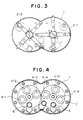
- Fig. 3 is a view from the arrow II in Fig. 2;
- Fig. 4 is a sectional view showing the geometrical relation of the motors in the two-cutter shield machine;
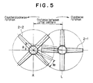
- Fig. 5 is an explanatory drawing of the permissible angle of deviation between the rotating cutter heads;
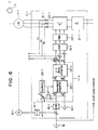
- Figs. 6 to 9 are detailed circuit diagrams, respectively, of each control unit in Fig. 1;
- Figs. 10 to 14 show another embodiment of the control system for synchronous rotation of the cutter heads according to the present invention, of which:
- Fig. 10 is a system configuration diagram of the control system for synchronous rotation of the cutter heads;
- Figs. 11 to 13 are detailed circuit diagrams of the control units in Fig. 10; and
- Fig. 14 is an explanatory drawing functionally showing the torque control.
- The embodiments of the control system for synchronous rotation of the cutter heads in a shield machine according to the present invention will be described in detail herebelow with reference to the drawings.
- Figs. 1 to 9 show the first embodiment of the present invention. Fig. 2 shows the whole structure of a two-cutter shield machine according to the present invention. As shown in Fig. 3, the
shield body 1 has a cross-section like a cocoon profile such as resulted from a partial superposition of two circles, and has provided at the front thereof two spoke-type rotating cutter heads 2-1 and 2-2 having the centers of rotation at the centers of the above-mentioned respective circles and which are disposed in nearly same planes, with the distance between the centers of the cutter heads selected to be larger than the excavating radius, and smaller than the diameter, of the rotating cutter heads. According to this embodiment, each of the rotating cutter heads 2-1 and 2-2 has four spokes and the phase difference between the cutter heads is selected to be 45 deg. - The rotating cutter heads 2-1 and 2-2 are driven independently of each other; the cutter head 2-1 is driven by an electric drive system comprising motors 4-1, 4-2 and 4-3 disposed inside a
bulkhead 3, namely, inside thebody 1 and which are provided with reduction gears 5-1, 5-2 and 5-3, respectively, while the cutter head 2-2 is driven by an electric drive system consisting of motors 4-4, 4-5 and 4-6 provided with reduction gears 5-4, 5-5 and 5-6, respectively. The rotation of the motors 4-1, 4-2 and 4-3 is reduced by the reduction gears 5-1, 5-2 and 5-3, respectively, and transmitted to the center shaft (L shaft) of the rotating cutter head 2-1 via the pinions mounted on the output shafts, respectively, of the reduction gears and gears in mesh with the respective pinions. Similarly, the rotation of the motors 4-4, 4-5 and 4-6 is slowed down by the reduction gears 5-4, 5-5 and 5-6, respectively, and transmitted to the center shaft (R shaft) of the rotating cutter head 2-2 via the pinions mounted on the output shafts, respectively, of the reduction gears and gears in mesh with the respective pinions. The sets of the above-mentioned pinions and gears are typically indicated with reference numerals 10-2 and 10-A. In addition, there are provided behind thebulkhead 3 and inside the body 1 a soil carry-outscrew conveyor 6,shield jack 7,erector 8 and so forth. Thus, a tunnel boring is done with the tunnel face excavation by the rotating cutter heads 2-1 and 2-2 and the thrust of theshield jack 7 using, as reaction receiver,segments 9 assembled by theerector 8. - Fig. 5 shows the counterrotation of the rotating cutter heads 2-1 and 2-2. In this drawing, it is assumed that the rotating cutter head 2-1 rotates clockwise while the rotating cutter head 2-2 rotates counterclockwise. There are set angles of deviation ϑ₁ and ϑ₂ from positions of rotation (indicated with solid line) at which there is a phase difference (45 deg.) between the rotating cutter heads 2-1 and 2-2 to the limit positions (indicated with two dot line) where the cutter heads do not interfere with each other. The allowable angle of deviation (±ϑ) between the cutter heads is selected taking account of some tolerance for minimum values of the angles of deviation ϑ₁ and ϑ₂ obtained at positions of rotation during one full rotation of each cutter head. Therefore, by rotating the two cutter heads synchronously with each other in such a manner that the angle of deviation from a predetermined phase difference can be kept within the allowable angle of deviation, the cutter heads will not interfere with each other.
- Fig. 1 is a system configuration diagram of one embodiment of the control system for synchronous rotation of the cutter heads according to the present invention. The system will be outlined with reference to this Figure. As shown, the motors 4-1, 4-2 and 4-3 in a group are coupled to the rotating cutter head 2-1 by means of the reduction gears 5-1, 5-2 and 5-3 and the pinions 10-1, 10-2 and 10-3, respectively, the motors 4-4, 4-5 and 4-6 in a group are coupled to the rotating cutter head 2-2 by means of the reduction gears 5-4, 5-5 and 5-6 and the pinions 10-4, 10-5 and 10-6, respectively. In the following description, the rotating cutter head 2-1 is assumed to be the first rotating cutter head providing for the reference of synchronous rotation, while the rotating cutter head 2-2 is to be the second rotating cutter head which rotates following up with the cutter head 2-1. Also, one (4-1) of the first motor group driving the rotating cutter head 2-1 is taken as the master motor of the group while the remaining two motors 4-2 and 4-3 of the same group are as ones subordinate to the master motor of the group. Similarly, one (4-4) of the second motor group driving the rotating cutter head 2-2 is taken as the master motor of the group while the remaining two motors 4-5 and 4-6 of the same group are as ones subordinate to the master motor of the group.
- According to this embodiment, squirrel-cage induction motors (IM) are used as cutter head driving motors and all the motors are of a same number of poles and same ratings.
- The control system according to the present invention comprises a controller consisting of control units 11-1 and 11-4 for speed-control of the motors 4-1 and 4-4 and control units 11-2, 11-3, 11-5 and 11-6 for torque-control of the motors 4-2, 4-3, 4-5 and 4-6. A vector control excellent in performance of dynamic speed control, employed for speed-control of the motors 4-1 and 4-4, will be described below.
- The control unit 11-1 converts, by means of a frequency-voltage converter (F/V) 14-1, an AC output of a pilot generator (PG) 13-1 connected directly to the motor 4-1 into a DC voltage proportional to a speed. A deviation between this DC voltage signal (speed detected value) and an L-shaft speed command (speed set value) from a
speed setter 12 is supplied to an automatic speed regulator (ASR) 15-1. The output of the automatic speed regulator 15-1 is taken as torque current set-value, and this signal and a magnetizing current set-value from a magnetic flux setter 16-1 are vector-composed by a vector calculator 17-1 to provide an equivalent two-phase current set-value which will be subject to a two/three phase conversion to provide a three-phase primary current set-value. A deviation between this primary current set-value and a primary current detected-value provided from a current detector 18-1 is supplied to an automatic current regulator (ACR) 19-1, of which the output is modulated by a pulse width modulator (PWM) 20-1 and applied as pulse width control signal to an inverter 22-1. A DC output from a rectifier 21-1 is converted into an AC power variable in frequency and voltage which is supplied to the motor 4-1, thereby controlling the speed of the latter. - The control unit 11-4 is composed of similar elements, provided that it is supplied with an R-shaft speed command (speed set-value) from the
speed setter 12 and the output signal (speed detected-value) from a pilot generator (PG) 13-4 connected directly to the motor 4-4, and in addition, with a detected-value signal of deviation angle (deviation angle detected-value) between the rotating cutter heads 2-1 and 2-2, provided from async generator 23 coupled to the L-shaft and async control transformer 24 connected to the R-shaft. The motor 4-4 is so speed-controlled that both the difference between the speed set- and detected-values and the deviation angle detected-value are zero. - Next, the above-mentioned deviation angle detection and speed correction with the deviation angle detected-value will be supplementarily described. As well known, each of the
sync generator 23 andsync control transformer 24 consists of a pair of a stator having a three-phase winding and a rotor having a single-phase winding. When the rotor of thesync generator 23 is excited with an AC voltage while the stator windings of thesync generator 23 connected to one (L-shaft) of the two shafts on which an angle of deviation is to be detected and thesync control transformer 24 connected to the other shaft (R-shaft), respectively, are interconnected to each other, a value corresponding to the magnitude of the angle of deviation between the two shafts and a voltage (deviation angle detected-value signal) of a polarity corresponding to whether the angle of deviation is positive or negative. In a signal conversion circuit (not shown), this output signal is detected, has the carrier wave of AC input frequency removed therefrom, and then it is subject to such an offset adjustment that the output when the synchronization is established is ±0. Therefore, by setting a relationship in phase between the rotor of thesync generator 23 and the rotor of thesync control transformer 24 so that when the phase difference increases from a state where the angle of deviation is zero, that is, a state in which the two shafts L and R are synchronous with each other with a predetermined phase difference (45 deg. in this embodiment), the deviation angle detected-value signal takes a positive polarity with respect to the speed command (same in polarity as the command) while, when the phase difference decreases from a state in which the angle of deviation is zero, the deviation angle detected-value signal takes a negative polarity (opposite polarity) with respect to the speed command, the deviation angle detected-value signal can be used as a speed correction signal for synchronization control, namely, to have the R-shaft follow up with the L-shaft. - The control units 11-2 and 11-3 control the primary current detected-value of the motor 4-1 provided from the current detector 18-1 as the primary current set-values of the motors 4-2 and 4-3, thereby controlling the torques generated by the motors 4-2 and 4-3 to be same as the torque generated by the motor 4-1. Similarly, the control units 11-5 and 11-6 control the primary current detected-value of the motor 4-4 provided from the current detector 18-4 as the primary current set-values of the motors 4-5 and 4-6, thereby controlling the torques generated by the motors 4-5 and 4-6 to be same as the torque generated by the motor 4-4.
- Next, the construction of each control unit will be described in detail with reference to Figs. 6 to 9.
- In Figs. 6 and 7, i₀ and i₂ indicate magnetizing current and torque (secondary) current, respectively, being the magnetic flux coordinate values, iα and iβ indicate currents of different phases through equivalent two-phase windings being stator coordinate values, iR, iS and iT indicate currents of different phases through the actual three-phase primary winding, ωS indicates a slip frequency, ωT indicates a rotation angle frequency and ω₁ indicates a primary frequency. The
second subscripts - The coordinate converter 25-1 is a calculator which, according to the following equations, converts the values of magnetizing current i₀₁ and torque current i₂₁ being the coordinate values (magnetic flux coordinate values) viewed from the position of the magnetic flux into equivalent two-phase currents iα1 and iβ1 being the coordinate values (stator coordinate values) viewed from the position of the stator winding:


where - φ:
- Magnetic flux phase
- In such parameter conversion, since the primary frequency (mains frequency) ω₁₁ of the motor 4-1 is variable, a slip frequency ωs1 is obtained by a divider 27-1 from the torque current set-value i₂₁* and magnetizing current set-value i₀₁*, a sum of this slip frequency and a rotation angle frequency ωr1 obtained from the output of the pulse generator 13-1 is taken as primary frequency set-value ω₁₁*, the output of an oscillator 28-1 which oscillates with ω₁₁* is made to correspond to a magnetic flux phase φ, and a coordinate conversion is done from the above-mentioned magnetic flux coordinate values i₀₁* and i₂₁* to stator coordinate values iα₁* and iβ₁* taking as a reference the magnetic flux phase φ. The automatic current regulator 19-1 controls the output voltage of the inverter 22-1 and the frequency so as to coincide with the primary current set-values iR1*, iS1* and 1T1*, thereby rotating the motor 4-1 at the set speed. The block 17-1 enclosed with two dot line in Fig. 6 is the vector calculator.
- The control unit 11-4 shown in Fig. 7 is composed of the similar elements to those illustrated and described in the foregoing, provided that the sum of the detected angle of deviation between the rotating cutter heads 2-1 and 2-2, obtained as output of the
sync control transformer 24 and the R-shaft speed command from thespeed setter 12 is compared with the speed detected-value from the pulse generator 13-4 and the deviation thus obtained is supplied to the automatic speed regulator 15-4. - The control units 11-2 and 11-3 shown in Fig. 8 are supplied with primary current detected-values iR1, iS1 and iT1 of the motor 4-1 as primary current set-values for the motors 4-2 and 4-3. This primary current set-value and deviations between the primary current detected-values iR2, iS2 and iT2 and iR3, iS3 and iT3 of the motors 4-2 and 4-3, obtained by the current detectors 18-2 and 18-3, are supplied to the automatic current regulators 19-2 and 19-3, the outputs of these automatic current regulators 19-2 and 19-3 are applied as pulse width control signals to the inverters 22-2 and 22-3, and DC outputs of the rectifiers 21-2 and 21-3 are converted into AC powers variable in frequency and voltage and supplied to the motors 4-2 and 4-3, thereby controlling the torques of the motors 4-2 and 4-3.
- Also in the control units 11-5 and 11-6 shown in Fig. 9, the primary current detected-values iR4, iS4 and iT4 of the motor 4-4 is taken as the primary current set-values for the motors 4-5 and 4-6, deviations between these primary current set-values and the primary current detected-values iR5, iS5 and iT5 and iR6, IS6 and IT6 of the motors 4-5 and 4-6, obtained by the current detectors 18-5 and 18-6, are supplied to the automatic current regulators 19-5 and 19-6, the outputs of the automatic current regulators 19-5 and 19-6 are modulated by the pulse width modulators (PWM) 20-5 and 20-6 into pulse-width modulated signals which are supplied to the inverters 22-5 and 22-6, and the DC outputs of the rectifiers 21-5 and 21-6 are converted into AC powers variable in frequency and voltage which are supplied to the motors 4-5 and 4-6, thereby controlling the torques of the motors 4-5 and 4-6.
- The master motors of the motor groups and the subordinate motors in the groups are mechanically coupled with one another by means of pinions and gears and rotated at a same speed. So, by making the currents in different phases coincide with each other, the torques generated of the motors can be maintained to be always constant, whereby it is possible for the master motors of the motor groups and the subordinate motors in the groups to uniformly share the torque.
- This embodiment is an example in which the present invention is applied to a two-cutter shield machine having two rotating cutter heads. The present invention is also applicable to a multi-cutter shield machine having more than two follow-up rotating cutter heads with a single reference rotating cutter head. Also, more than two motors may be used for driving each rotating cutter head.
- Next, another embodiment according to the present invention will be described with reference to Figs. 10 to 13. For the simplicity of illustration, the same elements as in Figs. 1 to 9 are only shown with the same reference numerals or symbols in Figs. 10 to 13 and will not be described.
- Fig. 10 is a system configuration diagram of the second embodiment. According to this embodiment, two rotating cutter heads are each driven by three motors (squirrel-cage induction motor) as in the preceding embodiment. Also in this embodiment, the cutter heads are synchronously rotated by controlling the speed of the master motors of the motor groups, which is similar to the first embodiment. For more accurate torque control of the subordinate motors in the motor groups, the subordinate motors are also subjected to vector control. To this end, the torque current component of the current detected-value of the master motor of each motor group is taken as torque command for the subordinate motors in the group, the supply voltage and frequency are so controlled that the torque current component of the current through the subordinate motors takes a value corresponding to the torque command, which is different from the first embodiment.
- As seen from Fig. 10, the control units 11-1 and 11-4 for speed-control of the motors 4-1 and 4-2, respectively, are provided with three/two phase converters 29-1 and 29-4, respectively, and coordinate converters (VD) 30-1 and 30-4, respectively, for obtaining a torque current component from the current detected-values of the motors 4-1 and 4-2, obtained by the current detectors 18-1 and 18-4, respectively, and a signal corresponding to the torque current component thus obtained is applied to the control units 11-2 and 11-3, and 11-5 and 11-6 as torque command for the motors 4-2 and 4-3, and 4-5 and 4-6. The three/two phase converters 29-1 and 29-4 and coordinate converters (VD) 30-1 and 30-4 are calculators which work in opposite manners to the previously-mentioned two/three phase converters 25-1 and 25-4 and coordinate converters 26-1 and 26-4, respectively.
- Figs. 11 and 12 show in further detail the circuit configurations of the control units 11-1 and 11-4, respectively. The control unit 11-1 shown in Fig. 11 feeds back to the automatic current regulator 19-1 the primary current detected-values iR1, iS1 and iT1 obtained by the current detector 18-1, converts these primary current detected-values iR1, iS1 and iT1 into equivalent two-phase values iα1 and iβ1 by the three/two phase converter 29-1, and further vector-decomposes these signals into a magnetizing current component i₀₁ and torque current component i₂₁ by the coordinate converter 30-1 which converts a stator coordinate value into a magnetic flux coordinate value. A DC value corresponding to the torque current component i₂₁ thus obtained is taken as a torque command for the motors 4-2 and 4-3.
- In this embodiment, the torque current component (real value of torque current) i₂₁ and magnetizing current component (real value of magnetizing current) i₀₁ delivered from the coordinate converter 30-1 are taken as feedback values and compared with a torque current set-value i₂₁* given by the automatic speed regulator 15-1 and a magnetizing current set-value i₀₁* given by the magnetic flux setter 16-1, and the output i₂₁** of the torque current regulator 31-1 and output i₀₁** of the magnetizing current regulator 32-1 are applied to the coordinate converter 25-1 of the vector calculator 17-1 to make such a vector composition that the deviation between the values compared as above is zero, thereby improving the accuracy of the speed control.
- The control unit 11-4 shown in Fig. 12 is similarly constructed and uses as torque command for the motors 4-5 and 4-6 the DC value corresponding to the torque current component i₂₄ delivered from the coordinate converter 30-4.
- Fig. 13 shows the construction of the control units for the motors 4-2, 4-3, 4-5 and 4-6, respectively taking the control unit 11-2 as typical one.
- As having been described, according to this embodiment, the motors 4-2, 4-3, and 4-5, 4-6 on the L- and R-shafts, respectively, are torque-controlled by a vector control. The configuration of the controls unit 11-2 shown in Fig. 13 is almost the same as that of the control units 11-1 and 11-4 shown in Figs. 11 and 12. The vector calculator 17-2 obtains a slip frequency ωS2 from the output i₂₂* of the torque current regulator 31-2 and output i₀₂* of the magnetizing current regulator 32-2 by the divider 27-2, takes as primary frequency set-value ω₁₂* the sum of the slip frequency ωs2 and the rotation angle frequency ωr2 obtained by converting the output of the pilot generator (PG) 13-2 by the frequency/voltage converter (F/V) 14-2, makes the output of the oscillator 28-2 which oscillates with ω₁₂* correspond to the magnetic flux phase φ, converts the magnetic flux coordinate values i₂₂* and i₀₂* into stator coordinate values iα2 and iβ2 by the coordinate converter 25-2 taking the magnetic flux phase φ as the reference, and further converts the stator coordinate values into the three-phase primary current set-values iR2*, iS2* and iT2* by the three/two phase converter 26-2. The automatic current regulator 19-2 controls the output voltage and frequency of the inverter 22-2 by operating the pulse width modulator (PWM) 20-2 in such a manner that the primary current set-values iR2, iS2 and iT2 of the motor 4-2, obtained by the current detector 18-2, are coincident with the primary current set-values iR2*, iS2* and iT2*, respectively.
- In addition, the primary current set values iR2, iS2 and iT2 are converted into equivalent two-phase values iα2 and iβ2 by the three/two phase converter 29-2, these values thus obtained are vector-decomposed by the coordinate converter 30-2 taking the magnetic flux phase φ as the reference, and the torque current component i₂₂ and magnetizing current component i₀₂ thus obtained are fed back to the torque current regulator 31-2 and magnetizing current regulator 32-2, respectively.
- In this control unit, torque control is done as follows. First, assume that the automatic speed regulator 15-2 indicated with a dash line is not provided, thus, there is not supplied any L-shaft speed command thereto and no signal from the F/V converter 14-2 is fed back thereto. The torque current regulator 31-2 works in such a manner, taking as torque current set-value i₂₂* an L-shaft motor torque command supplied from the coordinate converter 30-1 in the control unit 11-1, that the deviation between the torque current set-value and the feedback value of torque current component i₂₂ while the magnetizing current regulator 32-2 works in such as manner, taking as magnetizing current set-value i₀₂* the output from the magnetic flux setter 16-2, that the deviation between the magnetizing current set-value and the feedback value of the magnetizing current component i₀₂ becomes zero.
- Thus, the motor 4-2 is subject to such a torque control that the magnetizing current component i₀₂ of the primary current is maintained constant and the torque current component i₂₂ corresponds to the torque current component i₂₁ of the motor 4-1 to which the torque current component i₂₂ is supplied as torque command. The torque generated by the motor 4-2 will thus be kept always the same as the torque generated by the motor 4-1.
- Similarly, the torque generated by the motor 4-3 is so controlled as to be the same as the torque generated by the motor 4-1 by the L-shaft motor torque given by the coordinate converter 30-1 in the control unit 11-1. The torques generated by the motors 4-5 and 4-6 are so controlled as to be the same as the torque generated by the motor 4-4 by the R-shaft motor torque command given by the coordinate converter 30-4 in the control unit 11-4.
- The torque control may be effected for individual motors, but the following may also be adopted. Namely, as shown with dash-line block in Fig. 13, there is additionally provided an automatic speed regulator 15-2 to which L-shaft speed command and a feedback signal from the frequency/voltage converter (F/V) 14-2 are supplied for speed-control of the motor 4-2 normally taking as torque current set value i₂₂* the output of the automatic speed regulator 15-2 when supplied with the L-shaft speed command common to the motor 4-1, and when the torque current of the motor 4-1 becomes abnormally large due to the increase of the load torque, the torque command from the coordinate converter 30-1 is given a priority through a
diode 33 and the torque generated by the motor 4-2 is increased correspondingly. - Fig. 14 is an explanatory drawing of the torque control in case the primary voltage and frequency of the motor are variable. As the load torque to a master motor of a motor group increases, the control system increases the torque current of that motor in order to maintain the set speed. At this time, the speed vs. torque curve of the subordinate motors in the motor group rapidly goes from the solid-line portion to the dash-line portion correspondingly to the increase of the torque command as will be seen in Fig. 14, as in the increase of the set speed, but as the motor rotation speed is gear-bounded, the torque generated at this gear-bounded speed increases for the torque increment shown in Fig. 14 so that the torque sharing with a master motor of the motor group is balanced.
- According to this embodiment, the subordinate motors of the motor groups are torque-controlled by the vector control excellent in dynamic performance. Hence, a torque control can be done in quick response to a variation in torque of a master motor of each motor group.
- As having been described in the foregoing, the present invention provides a multi-cutter shield machine having a plurality of rotating cutter heads disposed in generally same planes, wherein the cutter heads are rotated synchronously with each other by the speed control of a master motor of a motor group which drives each rotating cutter head, while the subordinate motors in each motor group are so torque-controlled that the master motor of each motor group and the subordinate motors in the same group share the torque uniformly. Therefore, the plural cutter heads can be rotated synchronously with each other with such an allowable angle of deviation as will not cause any interference between them, without being affected by the imbalance in excavating and rotating resistances between the rotating cutter heads and also with the synchronization between the cutter heads not being disturbed by any imbalance in torque sharing between the plural motors driving the cutter heads.


Such calculation circuits are described in "Illustrated Construction and Concept of the Motor Control" by Fumio Harajima, Kanji Suzuki and Takayoshi Nakano, Ohm-sha (first edition, October 20, 1981), pp 185-198 "Vector Control".
Claims (3)
- A control system for controlling synchronous rotation of a plurality of rotating cutter heads (2-1,2-2) in a multi-cutter shield machine, said rotating cutter (2-1,2-2) heads are generally disposed in the same plane and the distance between the centers of the adjoining rotating cutter heads (2-1,2-2) is larger than the radius but smaller than the diameter of the rotating cutter heads (2-1,2-2), comprising
a plurality of electric drive systems to respectively and independently drive said plurality of rotating cutter heads (2-1,2-2), each drive system includes a plurality of motors (4-1,4-2,4-3;4-4,4-5,4-6) which are coupled to the respective cutter head (2-1,2-2) by means of a pinion (10-1,10-2,10-3,10-4,10-5,10-6) and reducing gears (5-1,5-2,5-3,5-4,5-5,5-6);
a control means for synchronously rotating the adjoining first and second ones of said rotating cutter heads (2-1,2-2) with an allowable deviation angle which will not cause interference between the first and the second cutter head (2-1,2-2);
said control means comprising:
a means (23,24) for detecting an angle of deviation, or the difference in rotation angle between the first and second rotating cutter heads (2-1,2-2), and for delivering a deviation angle detected value signal corresponding to the detected angle of deviation;
a first means (13-1) for detecting the rotation speed of a master motor (4-1) in the plurality of motors (4-1,4-2,4-3) comprising a first one of said electric drive systems which drives said first rotating cutter head (2-1), wherein said first means (13-1), delivers a rotation speed signal corresponding to the detected rotation speed of the master motor (4-1) of the first drive system;
a second means (13-4) for detecting the rotation speed of a master motor (4-4) in the plurality of motors (4-4,4-5,4-6) comprising a second one of said electric drive systems which drives said second rotating cutter head (2-2), wherein said second means (13-4) delivers a rotation speed signal corresponding to the detected rotation speed of the master motor (2-2) of the second drive system;
a speed setting (12) means for setting a speed command to the master motor of each of said first and second drive systems;
a first speed control means (11-1) for comparing the rotation speed signal delivered from said first means (13-1) with the speed command given by said speed setting means (12), and for adjusting the power supplied to the master motor (4-1) of the first drive system so that the deviation resulting from the comparison becomes zero;
a second speed control means (11-4) for comparing the rotation speed signal delivered from said second means (13-4) with the sum of said speed command and said deviation angle detected value signal, and for adjusting the power supplied to the master motor (4-4) of the second drive system so that the deviation resulted from the comparison becomes zero;
a first torque setting means (18-1) for detecting the current through the master motor (4-1) of the first drive system, and for setting a torque command based on a detected current value of the master motor (4-1) and for providing said torque command to the slave motors (4-2,4-3) in the first drive system;
a second torque setting means (18-4) detecting the current through the master motor (4-4) of the second drive system, and for setting a torque command based on a detected current value of the master motor (4-4) and for providing said torque command to the slave motors (4-5,4-6) in the second drive system; and
torque controlling means (11-2,11-3,11-5,11-6) for adjusting power supplied to the slave motors (4-2,4-3,4-5,4-6) in the first and second drive systems so that the torques generated by the slave motors (4-2,4-3,4-5,4-6) in the respective drive system are the same as the torques generated by the master motor (4-1,4-4) of the respective drive system. - The control system according to claim 1, wherein:
said motors (4-1,4-2,4,3;4-4,4-5,4-6) driving said first and second rotating cutter heads (2-1,2-2) are squirrel cage induction motors;
said first and second torque setting means (18-1,18-4) are so constructed as to detect primary currents in different phases of the master motors (4-1,4-4) of the first and second drive systems and deliver the detected current values as said torque commands;
and wherein said torque controlling means (11-2,11-3,11-5,11-6) comprises:
a current detecting means (18-2,18-3,18-5,18-6) for detecting primary currents in different phases of the slave motors (4-2,4-3,4-5,4-6) in said first and second drive systems, and for delivering current detected value signals corresponding to the detected current values;
a variable frequency and variable voltage power converting means (22-2,22-3,22-5,22-6) for adjusting the power supplied to the slave motors (4-2,4-3,4-5,4-6) in said first and second drive systems; and
a means (19-2,19-3,19-5,19-6) for comparing the torque commands from said first and second torque setting means (18-1,18-4) with said current detected value signals corresponding to the torque commands, and for delivering a control signal to said power converting means 22-2,22-3,22-5,22-6) so that the deviation resulting from the comparison becomes zero. - The control system according to claim 1, wherein:
said motors (4-1,4-2,4-3;4-4,4-5,4-6) driving said first and second rotating cutter heads (2-1,2-2) are squirrel cage induction motors;
said first and second torque setting means (18-1,18-4) are so constructed as to detect primary currents in different phases of the master motors (4-1,4-4) of the first and second drive systems, and deliver torque current components of the detected current values as torque commands;
and wherein said torque controlling means (11-2,11-3,11-5,11-6) comprises:
a current detecting means (18-2,18-3,18-5,18-6)for detecting primary currents in different phases of the slave motors (4-2,4-3,4-5,4-6) in said first and second drive systems, and for delivering current detected value signals corresponding to the detected current values;
a variable frequency and variable voltage power converting means (22-2,22-3,22-5,22-6) for adjusting the power supplied to the slave motors (4-2,4-3,4-5,4-6) in said first and second drive systems;
a means (17-2,17-3,17-5,17-6) for generating a constant magnetizing current component of the motor primary current based on the torque command values from said first and second torque setting means (18-1,18-4), and for calculating the primary current set values in different phases for making the torque current components having values corresponding to said torque command values; and
a means (19-2,19-3,19-5,19-6) for comparing said primary current set values in different phases with the values of the current detected value signal corresponding to the primary current set values, and for delivering a control signal to said power converting means (22-2,22-3,22-5,22-6) so that the deviation resulting from the comparison becomes zero.
Applications Claiming Priority (2)
| Application Number | Priority Date | Filing Date | Title |
|---|---|---|---|
| JP63299664A JP2562494B2 (en) | 1988-03-04 | 1988-11-29 | Cutter synchronous operation device for multiple shield machine |
| JP299664/88 | 1988-11-29 |
Publications (3)
| Publication Number | Publication Date |
|---|---|
| EP0375837A2 EP0375837A2 (en) | 1990-07-04 |
| EP0375837A3 EP0375837A3 (en) | 1991-04-10 |
| EP0375837B1 true EP0375837B1 (en) | 1994-11-23 |
Family
ID=17875480
Family Applications (1)
| Application Number | Title | Priority Date | Filing Date |
|---|---|---|---|
| EP89114913A Expired - Lifetime EP0375837B1 (en) | 1988-11-29 | 1989-08-11 | Control system for synchronous rotation of cutter heads, for use in shield machine |
Country Status (3)
| Country | Link |
|---|---|
| US (1) | US4939431A (en) |
| EP (1) | EP0375837B1 (en) |
| DE (1) | DE68919467T2 (en) |
Families Citing this family (10)
| Publication number | Priority date | Publication date | Assignee | Title |
|---|---|---|---|---|
| US5420485A (en) * | 1993-08-20 | 1995-05-30 | Forcam Inc. | Uncoordinated machine initialization system and method |
| EP1020617A1 (en) * | 1999-01-14 | 2000-07-19 | SHI Control Systems, Ltd. | Control apparatus for synchronous rotation of cutter heads, for a multiple shield excavator |
| BE1013174A3 (en) * | 1999-12-10 | 2001-10-02 | Picanol Nv | Method and drive system for a machine. |
| US6600278B1 (en) * | 2002-03-08 | 2003-07-29 | Abb Inc. | Clean power common buss variable frequency drive system |
| JP3680064B2 (en) * | 2003-04-21 | 2005-08-10 | ファナック株式会社 | Numerical controller |
| ES2549675T3 (en) * | 2007-01-26 | 2015-10-30 | Kawasaki Jukogyo Kabushiki Kaisha | Tunnel drilling machine |
| US10006462B2 (en) * | 2012-09-18 | 2018-06-26 | Regal Beloit America, Inc. | Systems and method for wirelessly communicating with electric motors |
| CN110666498B (en) * | 2019-10-21 | 2020-07-03 | 中铁隧道局集团有限公司 | Method for replacing hob cutter in normal pressure state in boulder area tunneling process |
| CN114320328B (en) * | 2022-01-05 | 2025-03-18 | 中铁工程装备集团有限公司 | A shield machine start-stop control method and device |
| CN116733485B (en) * | 2023-06-15 | 2026-02-17 | 中国铁建重工集团股份有限公司 | Single-motor-driven full-face tunnel boring machine and slag discharging control method thereof |
Citations (1)
| Publication number | Priority date | Publication date | Assignee | Title |
|---|---|---|---|---|
| JPH06299597A (en) * | 1993-04-16 | 1994-10-25 | Taisei Prefab Kk | Structure for horizontal joint of precast concrete member |
Family Cites Families (9)
| Publication number | Priority date | Publication date | Assignee | Title |
|---|---|---|---|---|
| US2320850A (en) * | 1939-04-25 | 1943-06-01 | Westinghouse Electric & Mfg Co | Control system |
| US3132293A (en) * | 1961-07-11 | 1964-05-05 | Gen Electric | Plural motor drive for rolling mill winding reel |
| US3447050A (en) * | 1965-10-05 | 1969-05-27 | Borg Warner | Ratio control system |
| JPS57197395A (en) * | 1981-05-29 | 1982-12-03 | Taiho Kensetsu Kk | Shield drilling method and machine |
| DE3151904C2 (en) * | 1981-12-30 | 1985-12-12 | Uranit GmbH, 5170 Jülich | Method for optimizing the power consumption of a large number of hysteresis motors connected in parallel |
| US4491767A (en) * | 1982-12-09 | 1985-01-01 | Canadian General Electric Company Limited | Synchronizing synchronous motors, motors prior to clutch closure |
| US4591772A (en) * | 1984-12-12 | 1986-05-27 | The United States Of America As Represented By The Administrator Of The National Aeronautics And Space Administration | Load positioning system with gravity compensation |
| GB2179980B (en) * | 1985-09-03 | 1988-09-21 | Anderson Strathclyde Plc | Combined afc side discharge unit and integral cutter unit |
| JPS6299597A (en) * | 1985-10-23 | 1987-05-09 | 大豊建設株式会社 | Shield excavator |
-
1989
- 1989-07-21 US US07/383,533 patent/US4939431A/en not_active Expired - Lifetime
- 1989-08-11 DE DE68919467T patent/DE68919467T2/en not_active Expired - Fee Related
- 1989-08-11 EP EP89114913A patent/EP0375837B1/en not_active Expired - Lifetime
Patent Citations (1)
| Publication number | Priority date | Publication date | Assignee | Title |
|---|---|---|---|---|
| JPH06299597A (en) * | 1993-04-16 | 1994-10-25 | Taisei Prefab Kk | Structure for horizontal joint of precast concrete member |
Also Published As
| Publication number | Publication date |
|---|---|
| DE68919467D1 (en) | 1995-01-05 |
| US4939431A (en) | 1990-07-03 |
| EP0375837A3 (en) | 1991-04-10 |
| EP0375837A2 (en) | 1990-07-04 |
| DE68919467T2 (en) | 1995-06-29 |
Similar Documents
| Publication | Publication Date | Title |
|---|---|---|
| US4939431A (en) | Control system for synchronous rotation of cutter heads, for use in shield machine | |
| US3919609A (en) | Method and circuit for reducing the torque ripple of a rotating-field machine | |
| US4361791A (en) | Apparatus for controlling a PWM inverter-permanent magnet synchronous motor drive | |
| US5461293A (en) | Rotor position detector | |
| EP0075023B1 (en) | Method of controlling an ac motor and device thereof | |
| US4458192A (en) | A.C. Motor drive apparatus | |
| EP0085541A1 (en) | Synchronous motor drive apparatus | |
| JPH0828972B2 (en) | Non-circulating current type cycloconverter control device | |
| EP0267583B1 (en) | Turbine helper drive apparatus | |
| FI94301B (en) | Engine control device | |
| EP0326333A2 (en) | Variable speed ac drive | |
| JP2872708B2 (en) | Cutter synchronous operation device of multiple shield excavator | |
| JP2562494B2 (en) | Cutter synchronous operation device for multiple shield machine | |
| US4164018A (en) | Method and apparatus for steering a spacecraft and regulating its onboard supply voltage | |
| EP1020617A1 (en) | Control apparatus for synchronous rotation of cutter heads, for a multiple shield excavator | |
| US3621350A (en) | Time integral control system | |
| JP2817403B2 (en) | Cutter synchronous operation device of multiple shield excavator | |
| JP3424120B2 (en) | Cutter synchronization controller for multiple shield machine | |
| Pankratov et al. | A doubly fed induction motor drive of a mine hoisting plant | |
| JPH0363396A (en) | Synchronous driving device of cutter of multi-shield machine | |
| JP2540177B2 (en) | Servo motor signal transmission equipment | |
| CA1080827A (en) | Method of steering a spacecraft and of regulating its onboard supply voltage | |
| GB2056183A (en) | Alternating current generating equipment | |
| SU936209A1 (en) | Device for interconnection of power systems | |
| JPH04107Y2 (en) |
Legal Events
| Date | Code | Title | Description |
|---|---|---|---|
| PUAI | Public reference made under article 153(3) epc to a published international application that has entered the european phase |
Free format text: ORIGINAL CODE: 0009012 |
|
| 17P | Request for examination filed |
Effective date: 19890811 |
|
| AK | Designated contracting states |
Kind code of ref document: A2 Designated state(s): DE FR GB |
|
| PUAL | Search report despatched |
Free format text: ORIGINAL CODE: 0009013 |
|
| AK | Designated contracting states |
Kind code of ref document: A3 Designated state(s): DE FR GB |
|
| 17Q | First examination report despatched |
Effective date: 19921020 |
|
| GRAA | (expected) grant |
Free format text: ORIGINAL CODE: 0009210 |
|
| AK | Designated contracting states |
Kind code of ref document: B1 Designated state(s): DE FR GB |
|
| ET | Fr: translation filed | ||
| REF | Corresponds to: |
Ref document number: 68919467 Country of ref document: DE Date of ref document: 19950105 |
|
| PLBE | No opposition filed within time limit |
Free format text: ORIGINAL CODE: 0009261 |
|
| STAA | Information on the status of an ep patent application or granted ep patent |
Free format text: STATUS: NO OPPOSITION FILED WITHIN TIME LIMIT |
|
| 26N | No opposition filed | ||
| REG | Reference to a national code |
Ref country code: GB Ref legal event code: IF02 |
|
| PGFP | Annual fee paid to national office [announced via postgrant information from national office to epo] |
Ref country code: DE Payment date: 20070809 Year of fee payment: 19 |
|
| PGFP | Annual fee paid to national office [announced via postgrant information from national office to epo] |
Ref country code: GB Payment date: 20070809 Year of fee payment: 19 |
|
| PGFP | Annual fee paid to national office [announced via postgrant information from national office to epo] |
Ref country code: FR Payment date: 20070808 Year of fee payment: 19 |
|
| GBPC | Gb: european patent ceased through non-payment of renewal fee |
Effective date: 20080811 |
|
| REG | Reference to a national code |
Ref country code: FR Ref legal event code: ST Effective date: 20090430 |
|
| PG25 | Lapsed in a contracting state [announced via postgrant information from national office to epo] |
Ref country code: FR Free format text: LAPSE BECAUSE OF NON-PAYMENT OF DUE FEES Effective date: 20080901 Ref country code: DE Free format text: LAPSE BECAUSE OF NON-PAYMENT OF DUE FEES Effective date: 20090303 |
|
| PG25 | Lapsed in a contracting state [announced via postgrant information from national office to epo] |
Ref country code: GB Free format text: LAPSE BECAUSE OF NON-PAYMENT OF DUE FEES Effective date: 20080811 |