EP0375593B1 - Adjustable spacer - Google Patents
Adjustable spacer Download PDFInfo
- Publication number
- EP0375593B1 EP0375593B1 EP89630228A EP89630228A EP0375593B1 EP 0375593 B1 EP0375593 B1 EP 0375593B1 EP 89630228 A EP89630228 A EP 89630228A EP 89630228 A EP89630228 A EP 89630228A EP 0375593 B1 EP0375593 B1 EP 0375593B1
- Authority
- EP
- European Patent Office
- Prior art keywords
- disposed
- spacer
- barrel
- pad
- recited
- Prior art date
- Legal status (The legal status is an assumption and is not a legal conclusion. Google has not performed a legal analysis and makes no representation as to the accuracy of the status listed.)
- Expired - Lifetime
Links
- 125000006850 spacer group Chemical group 0.000 title claims description 42
- 238000006073 displacement reaction Methods 0.000 claims description 3
- 230000000717 retained effect Effects 0.000 claims 1
- 238000009434 installation Methods 0.000 description 5
- 239000004677 Nylon Substances 0.000 description 1
- 238000006243 chemical reaction Methods 0.000 description 1
- 230000009977 dual effect Effects 0.000 description 1
- 230000000977 initiatory effect Effects 0.000 description 1
- 239000000463 material Substances 0.000 description 1
- 238000000034 method Methods 0.000 description 1
- 229920001778 nylon Polymers 0.000 description 1
- 238000000926 separation method Methods 0.000 description 1
- 238000009966 trimming Methods 0.000 description 1
Images

Classifications
-
- F—MECHANICAL ENGINEERING; LIGHTING; HEATING; WEAPONS; BLASTING
- F01—MACHINES OR ENGINES IN GENERAL; ENGINE PLANTS IN GENERAL; STEAM ENGINES
- F01D—NON-POSITIVE DISPLACEMENT MACHINES OR ENGINES, e.g. STEAM TURBINES
- F01D17/00—Regulating or controlling by varying flow
- F01D17/10—Final actuators
- F01D17/12—Final actuators arranged in stator parts
- F01D17/14—Final actuators arranged in stator parts varying effective cross-sectional area of nozzles or guide conduits
- F01D17/16—Final actuators arranged in stator parts varying effective cross-sectional area of nozzles or guide conduits by means of nozzle vanes
-
- F—MECHANICAL ENGINEERING; LIGHTING; HEATING; WEAPONS; BLASTING
- F16—ENGINEERING ELEMENTS AND UNITS; GENERAL MEASURES FOR PRODUCING AND MAINTAINING EFFECTIVE FUNCTIONING OF MACHINES OR INSTALLATIONS; THERMAL INSULATION IN GENERAL
- F16B—DEVICES FOR FASTENING OR SECURING CONSTRUCTIONAL ELEMENTS OR MACHINE PARTS TOGETHER, e.g. NAILS, BOLTS, CIRCLIPS, CLAMPS, CLIPS OR WEDGES; JOINTS OR JOINTING
- F16B39/00—Locking of screws, bolts or nuts
- F16B39/02—Locking of screws, bolts or nuts in which the locking takes place after screwing down
- F16B39/12—Locking of screws, bolts or nuts in which the locking takes place after screwing down by means of locknuts
-
- F—MECHANICAL ENGINEERING; LIGHTING; HEATING; WEAPONS; BLASTING
- F01—MACHINES OR ENGINES IN GENERAL; ENGINE PLANTS IN GENERAL; STEAM ENGINES
- F01D—NON-POSITIVE DISPLACEMENT MACHINES OR ENGINES, e.g. STEAM TURBINES
- F01D17/00—Regulating or controlling by varying flow
- F01D17/10—Final actuators
- F01D17/12—Final actuators arranged in stator parts
- F01D17/14—Final actuators arranged in stator parts varying effective cross-sectional area of nozzles or guide conduits
- F01D17/16—Final actuators arranged in stator parts varying effective cross-sectional area of nozzles or guide conduits by means of nozzle vanes
- F01D17/162—Final actuators arranged in stator parts varying effective cross-sectional area of nozzles or guide conduits by means of nozzle vanes for axial flow, i.e. the vanes turning around axes which are essentially perpendicular to the rotor centre line
-
- F—MECHANICAL ENGINEERING; LIGHTING; HEATING; WEAPONS; BLASTING
- F04—POSITIVE - DISPLACEMENT MACHINES FOR LIQUIDS; PUMPS FOR LIQUIDS OR ELASTIC FLUIDS
- F04D—NON-POSITIVE-DISPLACEMENT PUMPS
- F04D29/00—Details, component parts, or accessories
- F04D29/40—Casings; Connections of working fluid
- F04D29/52—Casings; Connections of working fluid for axial pumps
- F04D29/54—Fluid-guiding means, e.g. diffusers
- F04D29/56—Fluid-guiding means, e.g. diffusers adjustable
- F04D29/563—Fluid-guiding means, e.g. diffusers adjustable specially adapted for elastic fluid pumps
-
- F—MECHANICAL ENGINEERING; LIGHTING; HEATING; WEAPONS; BLASTING
- F16—ENGINEERING ELEMENTS AND UNITS; GENERAL MEASURES FOR PRODUCING AND MAINTAINING EFFECTIVE FUNCTIONING OF MACHINES OR INSTALLATIONS; THERMAL INSULATION IN GENERAL
- F16B—DEVICES FOR FASTENING OR SECURING CONSTRUCTIONAL ELEMENTS OR MACHINE PARTS TOGETHER, e.g. NAILS, BOLTS, CIRCLIPS, CLAMPS, CLIPS OR WEDGES; JOINTS OR JOINTING
- F16B31/00—Screwed connections specially modified in view of tensile load; Break-bolts
- F16B31/02—Screwed connections specially modified in view of tensile load; Break-bolts for indicating the attainment of a particular tensile load or limiting tensile load
- F16B31/021—Screwed connections specially modified in view of tensile load; Break-bolts for indicating the attainment of a particular tensile load or limiting tensile load by means of a frangible part
-
- F—MECHANICAL ENGINEERING; LIGHTING; HEATING; WEAPONS; BLASTING
- F16—ENGINEERING ELEMENTS AND UNITS; GENERAL MEASURES FOR PRODUCING AND MAINTAINING EFFECTIVE FUNCTIONING OF MACHINES OR INSTALLATIONS; THERMAL INSULATION IN GENERAL
- F16B—DEVICES FOR FASTENING OR SECURING CONSTRUCTIONAL ELEMENTS OR MACHINE PARTS TOGETHER, e.g. NAILS, BOLTS, CIRCLIPS, CLAMPS, CLIPS OR WEDGES; JOINTS OR JOINTING
- F16B41/00—Measures against loss of bolts, nuts, or pins; Measures against unauthorised operation of bolts, nuts or pins
- F16B41/005—Measures against unauthorised operation of bolts, nuts or pins
Definitions
- This invention relates to an adjustable spacer for maintaining a preselected minimum clearance between two relatively translatable members.
- variable stator vanes typically utilize one or more stages of variable stator vanes to adjust the flow area and direction of the annular flow of air in the compressor section.
- the variable vane stage typically comprises a plurality of circumferentially spaced vane airfoils extending radially with respect to the airfoil span across the annular air stream, and pivoted by an actuating linkage which includes an individual pivot arm for each vane airfoil connected to a unison ring encircling the exterior of the generally cylindrical engine housing and rotated circumferentially to simultaneously vary the angle of attack and nozzle outlet area of the entire variable vane stage.
- the engine housing or case is relatively rigid, while the unison ring is typically designed to be as light in weight as is consistent with the need to maintain an accurate positioning of each vane.
- the unison ring is thus typically supported by the engine housing having a plurality of bearing means distributed about the housing exterior for positioning and supporting the circumferentially movable unison ring.
- the simplest bearing arrangement is a plain bearing surface comprising a relatively flat pad or similar area in the outer surface of the engine housing which interacts with a similar flattened surface secured to the unison ring.
- Prior art means for maintaining a uniform spacing between the unison ring and the engine housing include pad members or sections disposed respectively in the housing and the inner diameter of the unison ring which are machined during assembly of the engine to the desired spacing. As will be appreciated by those familiar with this process, the repeated removal and reinstallation of the unison ring in order to machine the respective pads to the proper size is extremely time consuming and complex.
- a unison ring support arrangement is shown in US-A-2 933 234.
- An adjustable spacer for a gas turbine engine is shown in FR-A-1 111 358.
- a first member which is translatable relative to a second member is provided with an adjustable spacer for maintaining at least a minimum normal displacement between the two members.
- the spacer includes a pad bolt having a flattened head, preferably adapted to contact a corresponding flat surface on the second member, and which is positioned by an adjusting nut engaged with the first member.
- the adjusting nut is locked into position, following the initial adjustment of the pad bolt, by means of a lock nut engaging a threaded portion of the pad bolt which extends through a hollow bore in the adjusting nut.
- the lock nut has the dual function of retaining the pad bolt in an abutting relationship with the adjusting nut as well as locking the adjusting nut against rotation and hence loss of the initial spacer setting.
- One feature of the spacer according to the present invention is the combination of tamper resistance with overtorqueing protection. This is achieved by configuring the lock nut into a threaded portion and a headed portion connected by a frangible torque link. During installation of the spacer according to the present invention, the lock nut is tightened on the pad bolt by a wrench or other tool engaged with the headed portion. Upon reaching a preselected torque limit, the frangible link separates, with the headed portion being removed and discarded while the threaded portion remains tightly secured against the adjusting nut.
- the adjustable spacer of the present invention may also be secured more firmly by providing an antirotation means between the pad bolt and the first member.
- antirotation means includes an enlarged shaped portion of the pad bolt adjacent the flat end and configured to be received within a similarly shaped recess in the first member, the recess and head being shaped so as to prevent rotation when the pad bolt is secured in place.
- the adjustable spacer according to the present invention provides quick adjustment at the time of installation with automatic conversion to a tamper resistant, locked configuration.
- Figure 1 shows a gas turbine engine 10 having a compressor section 12 with a stage of variable compressor vanes 14 simultaneously positioned by an external unison ring 16.
- the unison ring 16 is reciprocated 18 by a linear actuator 20, or the like.
- the present invention relates to a plurality of adjustable spacers (not shown in Figure 1) distributed uniformly about the unison ring 16 for maintaining a fixed radial displacement between the ring 16 and the cylindrical engine case 19.
- FIG. 2 shows the various components of the adjustable spacer 20 prior to assembly.
- the unison ring 16 includes a bore 22 extending therethrough in the radial direction. Also shown is a shaped recess 24 disposed in the unison ring 16 at the radially inward end of the bore 22. A shoulder 26 adjacent the radially inward opening of the bore 22 is also visible.
- the spacer includes a cylindrical barrel 28 having an enlarged flanged end 30 and an internal threaded passage 32.
- the barrel 28 slides radially into the bore 22 with the flange 30 contacting the shoulder 26 for retaining the barrel 28 against further movement into the bore 22.
- the end 34 of the barrel opposite the flange 30 may be peened, staked, or otherwise deformed so as to retain the barrel 28 within the bore 22.
- the next component of the adjustable spacer 20 is a threaded adjusting nut 36 which includes an external threaded portion 38, an adjusting head 40 and an internal bore.
- the adjusting nut 36 engages the threaded portion 32 of the barrel 28 and may be adjusted radially as to position by rotation.
- a nylon insert 37 which engages the threads 38 of the adjusting nut 36 for preventing inadvertent rotation of the nut 36.
- This feature may equivalently be achieved by any one of a variety of known antirotation arrangements, including heli-coil, etc.
- a pad bolt 44 Received within the adjusting nut bore and extending therethrough is a pad bolt 44 having an elongated rod 46 extending radially through the adjusting nut 36 and further including a threaded portion 48 on the radially outer end thereof, and a substantially flat pad portion 50 disposed at the radially innermost end of the pad bolt 44 which includes a flattened surface 52 for engaging a similar flattened surface (not shown in Figure 2) on the exterior of the engine housing 19.
- the threaded portion 48 of the rod 46 is engaged by an internally threaded lock nut 54 which draws the pad bolt 44 radially against the adjusting nut 36 when tightened during assembly of the adjustable spacer 20.
- One other feature of the pad bolt 44 is an englarged shaped portion 56 disposed adjacent the pad portion 50 of the pad bolt 44, the enlarged shaped portion 56 being configured similarly to the recess 24 and received therein for preventing rotation of the pad bolt 44 relative to the unison ring 16.
- the shape of the recess 24 and shaped portion 56 may be an axial slot as shown in Figure 2, or any of a variety of noncylindrical shapes which will prevent rotation between the pad bolt 44 and the unison ring 16 when the shaped portion 56 is received within the recess 24.
- the assembled spacer 20 is shown in Figure 3 in a view taken in the plane of the unison ring 16 as the spacer 20 would appear assembled about an engine case 19.
- the threaded barrel 28 is secured within the ring 16 against radially outward movement by the engagement of the barrel flange 30 with the shoulder 26 formed in the unison ring 16.
- the adjusting nut 36 is positioned to extend radially inward of the flange 30, abutting the pad bolt 44 and thereby providing radial adjustment thereof relative to the unison ring 16.
- the relatively flat surface 52 of the pad 50 slidably engaged a smooth, corresponding surface 58 in the exterior of the engine housing 19.
- the smoothed surface 58 is formed in a removable slide plate 60 riveted 62 to a raised boss 64 or other thickened portion which may be cast or otherwise formed in the exterior of the engine housing 19.
- Adjustment of the spacer 20 during installation is most easily accomplished by providing a sized shim (not shown) positioned within the gap 66 between the pad surface 52 and the smooth casing surface 58.
- a sized shim is provided between each pad bolt 44 about the circumference of the unison ring 16.
- the adjusting nuts 36 are then rotated so as to drive the pad bolts 44 radially inward until all the pad bolts, preferably at least four, equally contact the installation shims.
- the spacer 20 is positively locked into position by application of the lock nut 54 to the radially extending, threaded end 48 of the pad bolt rod 46.
- the lock nut 54 is tightened down on the threaded portion 48 so as to contact the adjusting nut 36 and compress the pad bolt 44 against the radially inward end 42 of the adjusting nut 36.
- the shims are removed and the unison ring 16 is maintained at a fixed minimum distance from the engine case 19 as it is reciprocated 18 over the desired operating range.
- the lock nut 54 which includes a threaded portion 68 and a headed portion 70 joined by a frangible torque link 72.
- the lock nut 54 is torqued onto the threaded portion 48 of the pad bolt rod 46 until such time as the threaded portion 68 contacts the radially outer end of the adjusting nut 36.
- the assembler can increase the torque applied to the lock nut 54 until such time as the frangible torque link 72 reaches its design limit and fractures.
- the headed portion 70 is thus removed leaving the threaded portion 68 of the lock nut 54 engaged with the threaded end 48.
- the threaded portion 68 of the lock nut 54 is relatively smooth, without shaped surface features which could easily be engaged by a removing wrench or the like.
- the lock nut 54 after installation is relatively tamper resistant, while the provision of a frangible torque link having a design limit selected to match the optimum tightening torque for the lock nut 54, provides an inherently simple means for properly and positively locking the adjustable spacer 20 during assembly.
- Figure 4 shows the indicated view of Figure 3 taken transversely through the unison ring 16 showing the cylindrical barrel 28 and the pad bolt 44.
- the cylindrical barrel 28 may be equivalently provided by providing a threaded hole in the unison ring 16 with the proper interior diameter.
- the cylindrical barrel insert 28 is preferred in the spacer 20 according to the present invention due to enhanced materials properties which may be provided in an insert 28, as well as the reduced likelihood of crack initiation of propagation which is provided by such an insert 28.
- removal of the adjustable spacer, and in particular the threaded portion 68 of the lock nut 54 may be accomplished by providing the radially outer end of the pad bolt rod 46 with an internal keyway or other engaging recess 74 whereby the rod 46 may be held while a clamp or other gripping member engages the threaded portion 68 of the lock nut 54 and releases the pad bolt 44.
- a new lock nut 54 may then be placed on the threaded end 48 and used to resecure the adjustable spacer 20 following adjustment of the adjusting nut 36 as necessary.
- adjustable spacer according to the present invention is thus well suited to achieve the objects and advantages set forth hereinabove. It should also be noted that although disclosed and claimed in terms of the preferred embodiment illustrated by the accompanying figures and preceding description, the adjustable spacer according to the present invention may equivalently be embodied in a number of other configurations, with the scope thereof being limited only by the claims presented hereinbelow.
Landscapes
- Engineering & Computer Science (AREA)
- General Engineering & Computer Science (AREA)
- Mechanical Engineering (AREA)
- Control Of Turbines (AREA)
- Structures Of Non-Positive Displacement Pumps (AREA)
- Supercharger (AREA)
- Bolts, Nuts, And Washers (AREA)
- Valve Device For Special Equipments (AREA)
- Valve-Gear Or Valve Arrangements (AREA)
- Mechanical Treatment Of Semiconductor (AREA)
Description
- This invention relates to an adjustable spacer for maintaining a preselected minimum clearance between two relatively translatable members.
- Axial flow gas turbine engines occasionally utilize one or more stages of variable stator vanes to adjust the flow area and direction of the annular flow of air in the compressor section. The variable vane stage typically comprises a plurality of circumferentially spaced vane airfoils extending radially with respect to the airfoil span across the annular air stream, and pivoted by an actuating linkage which includes an individual pivot arm for each vane airfoil connected to a unison ring encircling the exterior of the generally cylindrical engine housing and rotated circumferentially to simultaneously vary the angle of attack and nozzle outlet area of the entire variable vane stage.
- The engine housing or case is relatively rigid, while the unison ring is typically designed to be as light in weight as is consistent with the need to maintain an accurate positioning of each vane. The unison ring is thus typically supported by the engine housing having a plurality of bearing means distributed about the housing exterior for positioning and supporting the circumferentially movable unison ring.
- The simplest bearing arrangement is a plain bearing surface comprising a relatively flat pad or similar area in the outer surface of the engine housing which interacts with a similar flattened surface secured to the unison ring. By maintaining a close clearance between such flat surfaces in the unison ring and engine housing, the actuating unison ring will be maintained concentric with the cylindrical engine housing, thereby minimizing any error in vane position which may result from flexing or warping of the unison ring.
- Prior art means for maintaining a uniform spacing between the unison ring and the engine housing include pad members or sections disposed respectively in the housing and the inner diameter of the unison ring which are machined during assembly of the engine to the desired spacing. As will be appreciated by those familiar with this process, the repeated removal and reinstallation of the unison ring in order to machine the respective pads to the proper size is extremely time consuming and complex. A unison ring support arrangement is shown in US-A-2 933 234. An adjustable spacer for a gas turbine engine is shown in FR-A-1 111 358.
- It is therefore an object of the present invention to provide an adjustable spacer for maintaining a minimum separation between two translating members.
- It is further an object of the present invention to provide a spacer which is adjustable with a minimum amount of additional tooling.
- It is still further an object of the present invention to provide a spacer which is positively locked in the desired position and which is resistant to subsequent adjustment or tampering.
- According to the present invention, a first member which is translatable relative to a second member is provided with an adjustable spacer for maintaining at least a minimum normal displacement between the two members. The spacer includes a pad bolt having a flattened head, preferably adapted to contact a corresponding flat surface on the second member, and which is positioned by an adjusting nut engaged with the first member.
- The adjusting nut is locked into position, following the initial adjustment of the pad bolt, by means of a lock nut engaging a threaded portion of the pad bolt which extends through a hollow bore in the adjusting nut. Thus, the lock nut has the dual function of retaining the pad bolt in an abutting relationship with the adjusting nut as well as locking the adjusting nut against rotation and hence loss of the initial spacer setting.
- One feature of the spacer according to the present invention is the combination of tamper resistance with overtorqueing protection. This is achieved by configuring the lock nut into a threaded portion and a headed portion connected by a frangible torque link. During installation of the spacer according to the present invention, the lock nut is tightened on the pad bolt by a wrench or other tool engaged with the headed portion. Upon reaching a preselected torque limit, the frangible link separates, with the headed portion being removed and discarded while the threaded portion remains tightly secured against the adjusting nut.
- The adjustable spacer of the present invention may also be secured more firmly by providing an antirotation means between the pad bolt and the first member. Such antirotation means includes an enlarged shaped portion of the pad bolt adjacent the flat end and configured to be received within a similarly shaped recess in the first member, the recess and head being shaped so as to prevent rotation when the pad bolt is secured in place.
- Unlike prior art spacers which may require shimming or trimming, the adjustable spacer according to the present invention provides quick adjustment at the time of installation with automatic conversion to a tamper resistant, locked configuration.
- Both these and other objects and advantages of the adjustable spacer according to the present invention will be apparent to those skilled in the art upon review of the following specification and the appended claims and drawing figures.
-
- Figure 1 shows an exterior, schematic view of a gas turbine engine with a variable vane stage and unison ring linkage.
- Figure 2 shows the adjustable spacer according to the present invention prior to assembly.
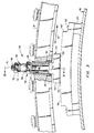
- Figure 3 shows the assembled adjustable spacer according to the present invention as it would appear installed in the gas turbine engine of Figure 1.
- Figure 4 shows a cross section of the unison ring and pad bolt as indicated in Figure 3.
- Referring now to the drawing figures, and in particular to Figure 1, the environment of the invention will be disclosed. Figure 1 shows a
gas turbine engine 10 having acompressor section 12 with a stage ofvariable compressor vanes 14 simultaneously positioned by anexternal unison ring 16. Theunison ring 16 is reciprocated 18 by alinear actuator 20, or the like. - The present invention relates to a plurality of adjustable spacers (not shown in Figure 1) distributed uniformly about the
unison ring 16 for maintaining a fixed radial displacement between thering 16 and thecylindrical engine case 19. - Figure 2 shows the various components of the
adjustable spacer 20 prior to assembly. Theunison ring 16 includes abore 22 extending therethrough in the radial direction. Also shown is ashaped recess 24 disposed in theunison ring 16 at the radially inward end of thebore 22. Ashoulder 26 adjacent the radially inward opening of thebore 22 is also visible. - The spacer includes a
cylindrical barrel 28 having an enlargedflanged end 30 and an internal threadedpassage 32. Thebarrel 28 slides radially into thebore 22 with theflange 30 contacting theshoulder 26 for retaining thebarrel 28 against further movement into thebore 22. As will be disclosed and shown below, theend 34 of the barrel opposite theflange 30 may be peened, staked, or otherwise deformed so as to retain thebarrel 28 within thebore 22. - The next component of the
adjustable spacer 20 is a threaded adjustingnut 36 which includes an external threadedportion 38, an adjustinghead 40 and an internal bore. The adjustingnut 36 engages the threadedportion 32 of thebarrel 28 and may be adjusted radially as to position by rotation. - Also shown in the assembled view of Figure 3 is a nylon insert 37 which engages the
threads 38 of the adjustingnut 36 for preventing inadvertent rotation of thenut 36. This feature may equivalently be achieved by any one of a variety of known antirotation arrangements, including heli-coil, etc. - Received within the adjusting nut bore and extending therethrough is a
pad bolt 44 having anelongated rod 46 extending radially through the adjustingnut 36 and further including a threadedportion 48 on the radially outer end thereof, and a substantiallyflat pad portion 50 disposed at the radially innermost end of thepad bolt 44 which includes aflattened surface 52 for engaging a similar flattened surface (not shown in Figure 2) on the exterior of theengine housing 19. The threadedportion 48 of therod 46 is engaged by an internally threadedlock nut 54 which draws thepad bolt 44 radially against the adjustingnut 36 when tightened during assembly of theadjustable spacer 20. - One other feature of the
pad bolt 44 is an englargedshaped portion 56 disposed adjacent thepad portion 50 of thepad bolt 44, the enlargedshaped portion 56 being configured similarly to therecess 24 and received therein for preventing rotation of thepad bolt 44 relative to theunison ring 16. The shape of therecess 24 andshaped portion 56 may be an axial slot as shown in Figure 2, or any of a variety of noncylindrical shapes which will prevent rotation between thepad bolt 44 and theunison ring 16 when theshaped portion 56 is received within therecess 24. - The assembled
spacer 20 is shown in Figure 3 in a view taken in the plane of theunison ring 16 as thespacer 20 would appear assembled about anengine case 19. The threadedbarrel 28 is secured within thering 16 against radially outward movement by the engagement of thebarrel flange 30 with theshoulder 26 formed in theunison ring 16. The adjustingnut 36 is positioned to extend radially inward of theflange 30, abutting thepad bolt 44 and thereby providing radial adjustment thereof relative to theunison ring 16. The relativelyflat surface 52 of thepad 50 slidably engaged a smooth,corresponding surface 58 in the exterior of theengine housing 19. - According to the preferred embodiment of the present invention, the smoothed
surface 58 is formed in aremovable slide plate 60 riveted 62 to a raisedboss 64 or other thickened portion which may be cast or otherwise formed in the exterior of theengine housing 19. - Adjustment of the
spacer 20 during installation is most easily accomplished by providing a sized shim (not shown) positioned within thegap 66 between thepad surface 52 and thesmooth casing surface 58. A sized shim is provided between eachpad bolt 44 about the circumference of theunison ring 16. The adjustingnuts 36 are then rotated so as to drive thepad bolts 44 radially inward until all the pad bolts, preferably at least four, equally contact the installation shims. - Following the initial positioning of the
pad bolts 44, thespacer 20 according to the present invention is positively locked into position by application of thelock nut 54 to the radially extending, threadedend 48 of thepad bolt rod 46. Thelock nut 54 is tightened down on the threadedportion 48 so as to contact the adjustingnut 36 and compress thepad bolt 44 against the radiallyinward end 42 of the adjustingnut 36. At this time the shims are removed and theunison ring 16 is maintained at a fixed minimum distance from theengine case 19 as it is reciprocated 18 over the desired operating range. - Another feature of the
spacer 20 according to the present invention is provided by thelock nut 54 which includes a threadedportion 68 and a headedportion 70 joined by afrangible torque link 72. During assembly of theadjustable spacer 20 according to the present invention, thelock nut 54 is torqued onto the threadedportion 48 of thepad bolt rod 46 until such time as the threadedportion 68 contacts the radially outer end of the adjustingnut 36. By engaging the headedportion 70 of thelock nut 54 with a simple wrench or other tool, the assembler can increase the torque applied to thelock nut 54 until such time as thefrangible torque link 72 reaches its design limit and fractures. The headedportion 70 is thus removed leaving the threadedportion 68 of thelock nut 54 engaged with the threadedend 48. As will be noted from the drawings, the threadedportion 68 of thelock nut 54 is relatively smooth, without shaped surface features which could easily be engaged by a removing wrench or the like. Thus, thelock nut 54 after installation is relatively tamper resistant, while the provision of a frangible torque link having a design limit selected to match the optimum tightening torque for thelock nut 54, provides an inherently simple means for properly and positively locking theadjustable spacer 20 during assembly. - Finally, Figure 4 shows the indicated view of Figure 3 taken transversely through the
unison ring 16 showing thecylindrical barrel 28 and thepad bolt 44. It should be noted that thecylindrical barrel 28 may be equivalently provided by providing a threaded hole in theunison ring 16 with the proper interior diameter. Thecylindrical barrel insert 28 is preferred in thespacer 20 according to the present invention due to enhanced materials properties which may be provided in aninsert 28, as well as the reduced likelihood of crack initiation of propagation which is provided by such aninsert 28. - Finally, removal of the adjustable spacer, and in particular the threaded
portion 68 of thelock nut 54 may be accomplished by providing the radially outer end of thepad bolt rod 46 with an internal keyway or other engaging recess 74 whereby therod 46 may be held while a clamp or other gripping member engages the threadedportion 68 of thelock nut 54 and releases thepad bolt 44. Anew lock nut 54 may then be placed on the threadedend 48 and used to resecure theadjustable spacer 20 following adjustment of the adjustingnut 36 as necessary. - The adjustable spacer according to the present invention is thus well suited to achieve the objects and advantages set forth hereinabove. It should also be noted that although disclosed and claimed in terms of the preferred embodiment illustrated by the accompanying figures and preceding description, the adjustable spacer according to the present invention may equivalently be embodied in a number of other configurations, with the scope thereof being limited only by the claims presented hereinbelow.
Claims (7)
- An adjustable spacer (20) for maintaining a minimum normal displacement between a first member (16) and a relatively flat surface (58) disposed in a second member (19), comprising:
a cylindrical barrel (28) having a threaded axial passage (32) disposed therein, further having an external flange (30) disposed about one end thereof, the barrel received within a close fitting hole (22) disposed through the first member (16), characterized in that the flanged end of the barrel engages an annular shoulder (26) within said hole, and further comprising:
an adjustable nut (36), disposed within the threaded passage (32) and including an externally threaded surface (38) engaged therewith, further including the first end (42) projecting past the flanged end of the barrel (28) and a second end (40) projecting past the other end of the barrel (28) opposite the flanged end thereof, a pad bolt (44), including a flattened pad end (52), for contacting the relatively flat surface (58), and a rod portion (46) extending perpendicular to the flat surface (58) and through the central passage in the adjusting nut (36), said bolt portion including an externally threaded portion (48) at the end thereof opposite the pad end, and
a lock nut (54), having internal threads engaging the threaded portion (48) of the pad bolt, said pad bolt contacting the first end of the adjusting nut (36) when the lock nut (54) is engaged securely against the second (40) end of the adjusting nut (36). - The spacer as recited in Claim 1, wherein
the second member (19) is a cylindrical housing and the relatively flat surface (58) is disposed on the exterior thereof, and wherein
the first member (16) is annular and disposed coaxially about the housing, the first member being disposed radially with respect to the housing by the spacer (20). - The spacer as recited in Claim 2, wherein
the annular member (16) is a unison ring cooperatively linked to a plurality of variable position stator vanes (14) disposed within the cylindrical housing. - The spacer as recited in Claim 3, wherein the cylindrical barrel (28) within the hole in the first member (16) is deformed at the end (34) opposite the flanged end thereof, thereby being retained within the first member (16).
- The spacer as recited in Claim 1, further comprising
antirotation means, disposed between the pad bolt (44) and the first member (16), including
an enlarged recess disposed in the first member (16) adjacent the flanged end of the cylindrical barrel (28), and wherein
the pad bolt (44) includes an enlarged portion (56) shaped to engage the recess (24) in the first member, the shaped portion and the recess configured to be noncylindrical with respect to the axis of the barrel. - The spacer as recited in Claim 1 wherein the lock nut (54) includes
a headed portion disposed opposite the adjusting nut, the headed portion (70) joined to the threaded portion of the lock nut by a frangible torque link (72), said torque link adapted to fracture upon imposition of a torque higher than a preselected limit. - The spacer as recited in Claim 1 further comprising
means disposed between the cylindrical barrel (28) and the adjusting nut (36) for preventing inadvertent rotation therebetween.
Applications Claiming Priority (2)
| Application Number | Priority Date | Filing Date | Title |
|---|---|---|---|
| US287353 | 1981-07-27 | ||
| US07/287,353 US4925364A (en) | 1988-12-21 | 1988-12-21 | Adjustable spacer |
Publications (2)
| Publication Number | Publication Date |
|---|---|
| EP0375593A1 EP0375593A1 (en) | 1990-06-27 |
| EP0375593B1 true EP0375593B1 (en) | 1992-11-11 |
Family
ID=23102524
Family Applications (1)
| Application Number | Title | Priority Date | Filing Date |
|---|---|---|---|
| EP89630228A Expired - Lifetime EP0375593B1 (en) | 1988-12-21 | 1989-12-19 | Adjustable spacer |
Country Status (6)
| Country | Link |
|---|---|
| US (1) | US4925364A (en) |
| EP (1) | EP0375593B1 (en) |
| JP (1) | JP2749915B2 (en) |
| KR (1) | KR0150194B1 (en) |
| DE (1) | DE68903485T2 (en) |
| NO (1) | NO171870C (en) |
Families Citing this family (58)
| Publication number | Priority date | Publication date | Assignee | Title |
|---|---|---|---|---|
| US5279031A (en) * | 1988-12-06 | 1994-01-18 | Alliedsignal Inc. | High temperature turbine engine structure |
| US5116158A (en) * | 1988-12-06 | 1992-05-26 | Allied-Signal Inc. | High temperature turbine engine structure |
| US5228284A (en) * | 1988-12-06 | 1993-07-20 | Allied-Signal Inc. | High temperature turbine engine structure |
| US5096375A (en) * | 1989-09-08 | 1992-03-17 | General Electric Company | Radial adjustment mechanism for blade tip clearance control apparatus |
| US5020204A (en) * | 1989-11-28 | 1991-06-04 | Eugene Desair | Tool for aligning the connecting of an exhaust manifold to an engine block |
| US5205692A (en) * | 1992-04-30 | 1993-04-27 | Ford Motor Company | Three-axes variability compensating fastener |
| US5271713A (en) * | 1992-10-05 | 1993-12-21 | Deere & Company | Adjustable inlet for a harvester fan |
| FR2699595B1 (en) * | 1992-12-23 | 1995-01-20 | Snecma | Device for guiding in rotation a control ring for pivoting vanes. |
| DE19516382A1 (en) * | 1995-05-04 | 1996-11-07 | Deutsche Forsch Luft Raumfahrt | Adjustment ring |
| US5577710A (en) * | 1995-06-08 | 1996-11-26 | Kirby; George T. | Fence extension assembly |
| US5624221A (en) * | 1995-07-21 | 1997-04-29 | Hartwell Corporation | Multiple speed fastener |
| US5775652A (en) * | 1995-11-16 | 1998-07-07 | A.C.T. Enterprises, Inc. | Theatrical lighting clamp |
| US6425564B1 (en) * | 1999-09-01 | 2002-07-30 | Joshua Harnik | Sprinkler head installation tool |
| US6367819B1 (en) * | 2000-03-20 | 2002-04-09 | Ole S. Andersen | Shock absorbing skateboard truck assembly |
| US6884025B2 (en) * | 2002-09-30 | 2005-04-26 | United Technologies Corporation | Shim lock/pin anti-rotation bumper design |
| US7681620B2 (en) * | 2003-01-30 | 2010-03-23 | Parma Shutter Technologies Ltd | Stacking mechanism |
| TWM257413U (en) * | 2003-10-29 | 2005-02-21 | Chin-Chih Lin | Improved clamping seat |
| GB0413866D0 (en) * | 2004-06-21 | 2004-07-21 | Bas Components Ltd | Captive fastener |
| FR2879686B1 (en) * | 2004-12-16 | 2007-04-06 | Snecma Moteurs Sa | STATOR TURBOMACHINE COMPRISING A RECTIFIER AUBES STAGE ACTED BY A ROTATING CROWN WITH AUTOMATIC CENTERING |
| FR2882577A1 (en) * | 2005-02-25 | 2006-09-01 | Snecma Moteurs Sa | Actuating ring`s centering adjusting device for rotary blade of turbomachine, has brake shoe comprising rod with longitudinal groove, and washer comprising radial pin engaged in groove and radial slots engaged in slots of cavity of ring |
| FR2882578B1 (en) * | 2005-02-25 | 2007-05-25 | Snecma Moteurs Sa | DEVICE FOR ADJUSTING THE CENTERING OF A SYNCHRONIZATION RING FOR THE CONTROL OF TURBOMACHINE SWIVELING BLADES |
| EP1811135A1 (en) * | 2006-01-23 | 2007-07-25 | ABB Turbo Systems AG | Variable guiding device |
| FR2897121B1 (en) * | 2006-02-09 | 2008-05-02 | Snecma Sa | DEVICE FOR ADJUSTING THE CENTERING OF A SYNCHRONIZATION RING FOR THE CONTROL OF TURBOMACHINE SWIVELING BLADES |
| US7845602B1 (en) | 2006-02-09 | 2010-12-07 | Primos, Inc. | Telescoping support stand apparatus |
| US8146876B1 (en) | 2006-02-09 | 2012-04-03 | Primos, Inc. | Telescoping support stand apparatus |
| FR2902454A1 (en) * | 2006-06-16 | 2007-12-21 | Snecma Sa | TURBOMACHINE STATOR COMPRISING A FLOOR OF ADJUSTERS ADJUSTED BY A ROTATING CROWN WITH AUTOMATIC CENTERING |
| US8092157B2 (en) * | 2007-12-19 | 2012-01-10 | United Technologies Corporation | Variable turbine vane actuation mechanism having a bumper ring |
| PT2245254E (en) * | 2008-02-15 | 2011-11-04 | Hunter Douglas Ind Bv | Louver rotating mechanism |
| EP2107217A1 (en) * | 2008-03-31 | 2009-10-07 | Siemens Aktiengesellschaft | Unison ring assembly for an axial compressor casing |
| US8015667B2 (en) * | 2009-02-16 | 2011-09-13 | Hamilton Sundstrand Corporation | Controlled rigging |
| US8668444B2 (en) | 2010-09-28 | 2014-03-11 | General Electric Company | Attachment stud for a variable vane assembly of a turbine compressor |
| US8714916B2 (en) | 2010-09-28 | 2014-05-06 | General Electric Company | Variable vane assembly for a turbine compressor |
| US8794910B2 (en) * | 2011-02-01 | 2014-08-05 | United Technologies Corporation | Gas turbine engine synchronizing ring bumper |
| US8864450B2 (en) | 2011-02-01 | 2014-10-21 | United Technologies Corporation | Gas turbine engine synchronizing ring bumper |
| FR2983924B1 (en) | 2011-12-09 | 2013-11-22 | Snecma | ANNULAR HOUSING FOR A TURBOMACHINE COMPRESSOR |
| US20130322985A1 (en) * | 2012-05-31 | 2013-12-05 | United Technologies Corporation | Retention assembly including sleeve |
| US9945411B2 (en) | 2012-08-31 | 2018-04-17 | United Technologies Corporation | Self-anti-rotating dual lock washer |
| US20140093362A1 (en) | 2012-09-28 | 2014-04-03 | United Technologies Corporation | Gas turbine engine components and method of assembly |
| US9822651B2 (en) | 2012-09-28 | 2017-11-21 | United Technologies Corporation | Synchronization ring runner with cradle |
| US9617869B2 (en) * | 2013-02-17 | 2017-04-11 | United Technologies Corporation | Bumper for synchronizing ring of gas turbine engine |
| US9863468B2 (en) | 2013-09-17 | 2018-01-09 | Sikorsky Aircraft Corporation | Rod end wear prevention |
| GB201317006D0 (en) * | 2013-09-25 | 2013-11-06 | Rolls Royce Plc | Component for attaching to a wall |
| GB2527297B (en) * | 2014-06-16 | 2016-08-17 | Rolls Royce Plc | An assembly |
| DE102014219552A1 (en) * | 2014-09-26 | 2016-03-31 | Rolls-Royce Deutschland Ltd & Co Kg | Guide vane adjusting a gas turbine |
| EP3000985B1 (en) | 2014-09-29 | 2021-05-26 | Rolls-Royce North American Technologies, Inc. | Unison ring self-centralizers and method of centralizing |
| FR3029564B1 (en) * | 2014-12-09 | 2018-03-09 | Safran Aircraft Engines | CONTROL RING OF A VARIABLE SHIFT AUBRA STAGE FOR A TURBOMACHINE |
| FR3029562B1 (en) * | 2014-12-09 | 2016-12-09 | Snecma | CONTROL RING OF A VARIABLE SHIFT AUBRA STAGE FOR A TURBOMACHINE |
| EP3283777B1 (en) | 2015-04-17 | 2024-06-05 | NMC Group, Inc. | Hybrid composite-metal breakaway nut fastener |
| GB2557565A (en) * | 2016-07-18 | 2018-06-27 | Rolls Royce Plc | Variable stator vane mechanism |
| GB201614803D0 (en) * | 2016-09-01 | 2016-10-19 | Rolls Royce Plc | Variable stator vane rigging |
| JP6286521B1 (en) * | 2016-12-19 | 2018-02-28 | 株式会社トープラ | Male thread member |
| US10495108B2 (en) * | 2017-01-31 | 2019-12-03 | Honeywell International Inc. | Variable vane devices containing rotationally-driven translating vane structures and methods for the production thereof |
| US10753224B2 (en) * | 2017-04-27 | 2020-08-25 | General Electric Company | Variable stator vane actuator overload indicating bushing |
| GB201711582D0 (en) * | 2017-07-19 | 2017-08-30 | Rolls Royce Plc | Unison ring assembly |
| FR3077851B1 (en) * | 2018-02-09 | 2020-01-17 | Safran Aircraft Engines | CONTROL ASSEMBLY OF A VARIABLE SETTING BLADE STAGE FOR A TURBOMACHINE |
| US10815820B2 (en) | 2019-02-05 | 2020-10-27 | Raytheon Technologies Corporation | Integral shear locking bumper for gas turbine engine |
| US11486271B1 (en) * | 2021-10-15 | 2022-11-01 | Pratt & Whitney Canada Corp. | Adjustable mount for engine accessory |
| US12092142B1 (en) * | 2023-12-15 | 2024-09-17 | Fernando Parajon | IPR solenoid retaining nut |
Family Cites Families (21)
| Publication number | Priority date | Publication date | Assignee | Title |
|---|---|---|---|---|
| BE496713A (en) * | 1949-07-01 | |||
| US2858104A (en) * | 1954-02-04 | 1958-10-28 | A V Roe Canada Ltd | Adjustable gas turbine shroud ring segments |
| FR1111358A (en) * | 1954-02-04 | 1956-02-27 | Canadian Patents Dev | Adjustable casing ring segments for gas turbines |
| US2933234A (en) * | 1954-12-28 | 1960-04-19 | Gen Electric | Compressor stator assembly |
| US2924375A (en) * | 1955-05-18 | 1960-02-09 | Gen Electric | Positioning device |
| GB1081955A (en) * | 1964-10-16 | 1967-09-06 | English Electric Co Ltd | Improvements in or relating to turbines |
| US3496628A (en) * | 1965-04-28 | 1970-02-24 | Usa | Method of joining thin-walled members,particularly in casings for gas turbine engines |
| US3458118A (en) * | 1967-08-21 | 1969-07-29 | Gen Electric | Low profile stator adjusting mechanism |
| US3487992A (en) * | 1967-11-01 | 1970-01-06 | Gen Electric | Stator adjusting mechanism for axial flow compressors |
| US3444775A (en) * | 1968-02-16 | 1969-05-20 | Lockheed Aircraft Corp | Nut formed with multiple torque-off collars |
| US3512447A (en) * | 1968-09-09 | 1970-05-19 | Rudolph Marion Vaughn | Frangible nut fastener |
| US3685920A (en) * | 1971-02-01 | 1972-08-22 | Gen Electric | Actuation ring for variable geometry compressors or gas turbine engines |
| US3779665A (en) * | 1972-09-22 | 1973-12-18 | Gen Electric | Combined variable angle stator and windmill control system |
| DE2253030A1 (en) * | 1972-10-28 | 1974-05-09 | Sljusarew | DEVICE FOR BLADE ADJUSTMENT OF THE CONTROL UNIT OF A FLOW MACHINE |
| US4400135A (en) * | 1981-04-06 | 1983-08-23 | General Motors Corporation | Vane actuation system |
| US4373859A (en) * | 1981-09-23 | 1983-02-15 | General Motors Corporation | Unison ring support system |
| CH661772A5 (en) * | 1983-05-31 | 1987-08-14 | Escher Wyss Ag | AXIAL TURBO MACHINE. |
| FR2556410B1 (en) * | 1983-12-07 | 1986-09-12 | Snecma | DEVICE FOR CENTERING THE INSIDE RING OF A VARIABLE TIMING FINS STATOR |
| FR2608678B1 (en) * | 1986-12-17 | 1991-02-08 | Snecma | VARIABLE SETTING BLADE CONTROL DEVICE FOR TURBOMACHINE RECTIFIER |
| GB2206381B (en) * | 1987-06-30 | 1991-10-09 | Rolls Royce Plc | A variable stator vane arrangement for a compressor |
| US4826399A (en) * | 1988-05-06 | 1989-05-02 | General Motors Corporation | Unison ring mounting arrangement |
-
1988
- 1988-12-21 US US07/287,353 patent/US4925364A/en not_active Expired - Lifetime
-
1989
- 1989-12-05 NO NO894852A patent/NO171870C/en unknown
- 1989-12-19 DE DE8989630228T patent/DE68903485T2/en not_active Expired - Fee Related
- 1989-12-19 EP EP89630228A patent/EP0375593B1/en not_active Expired - Lifetime
- 1989-12-20 KR KR1019890019011A patent/KR0150194B1/en not_active Expired - Fee Related
- 1989-12-21 JP JP1332482A patent/JP2749915B2/en not_active Expired - Fee Related
Also Published As
| Publication number | Publication date |
|---|---|
| JP2749915B2 (en) | 1998-05-13 |
| KR0150194B1 (en) | 1998-11-02 |
| NO171870C (en) | 1993-05-12 |
| KR900010206A (en) | 1990-07-06 |
| DE68903485D1 (en) | 1992-12-17 |
| EP0375593A1 (en) | 1990-06-27 |
| NO171870B (en) | 1993-02-01 |
| DE68903485T2 (en) | 1993-04-08 |
| NO894852D0 (en) | 1989-12-05 |
| NO894852L (en) | 1990-06-22 |
| US4925364A (en) | 1990-05-15 |
| JPH02215936A (en) | 1990-08-28 |
Similar Documents
| Publication | Publication Date | Title |
|---|---|---|
| US4925364A (en) | Adjustable spacer | |
| US7223066B2 (en) | Variable vane arrangement for a turbomachine | |
| US6641326B2 (en) | Removable stud for joining casing flanges | |
| US9033666B2 (en) | Means for locking a sealing ring on a turbine disk | |
| US6019574A (en) | Mismatch proof variable stator vane | |
| US11572889B2 (en) | Blade pivot of adjustable orientation and of reduced bulk for a turbomachine fan hub | |
| US8784043B2 (en) | Device for controlling variable-pitch blades in a turbomachine compressor | |
| EP2949878B1 (en) | A variable stator vane arrangement | |
| US20040240989A1 (en) | Variable vane arrangement for a turbomachine | |
| US6209198B1 (en) | Method of assembling a variable stator vane assembly | |
| US20050265846A1 (en) | Balance assembly for rotary turbine component and method for installing and/or adjusting balance weight | |
| US5141394A (en) | Apparatus and method for supporting a vane segment in a gas turbine | |
| US10393145B2 (en) | Asymmetric alignment system for a variable stator vane | |
| US20030123986A1 (en) | Device for immobilizing blades in a slot of a disk | |
| JPS63154801A (en) | Rotor for turbomachine and assembling method thereof | |
| EP4219917B1 (en) | Anti-rotation device for fasteners | |
| EP3722564B1 (en) | Vane arm assembly for a gas turbine engine, corresponding method of redundantly axially retaining a vane arm, and gas turbine engine | |
| US10502059B2 (en) | Alignment tie rod device and method of utilization | |
| US10941668B2 (en) | Assembly for a turbomachine comprising a distributor, a structural element of the turbomachine, and an attachment device | |
| US5000659A (en) | Temporary locking system for variably settable stator blades | |
| EP3219931B1 (en) | Vane assembly and corresponding gas turbine engine | |
| US3073569A (en) | Blade mounting structure for a fluid flow machine | |
| US20040265119A1 (en) | Control lever attachment with play compensation for blades with variable setting angles | |
| US20230287799A1 (en) | Device for fixing position of adjustable rows of guide vanes of turbomachine | |
| JPH02252904A (en) | Stationary blade fitting structure |
Legal Events
| Date | Code | Title | Description |
|---|---|---|---|
| PUAI | Public reference made under article 153(3) epc to a published international application that has entered the european phase |
Free format text: ORIGINAL CODE: 0009012 |
|
| AK | Designated contracting states |
Kind code of ref document: A1 Designated state(s): BE DE FR GB |
|
| 17P | Request for examination filed |
Effective date: 19901030 |
|
| 17Q | First examination report despatched |
Effective date: 19920129 |
|
| GRAA | (expected) grant |
Free format text: ORIGINAL CODE: 0009210 |
|
| AK | Designated contracting states |
Kind code of ref document: B1 Designated state(s): BE DE FR GB |
|
| ET | Fr: translation filed | ||
| REF | Corresponds to: |
Ref document number: 68903485 Country of ref document: DE Date of ref document: 19921217 |
|
| PLBE | No opposition filed within time limit |
Free format text: ORIGINAL CODE: 0009261 |
|
| STAA | Information on the status of an ep patent application or granted ep patent |
Free format text: STATUS: NO OPPOSITION FILED WITHIN TIME LIMIT |
|
| 26N | No opposition filed | ||
| REG | Reference to a national code |
Ref country code: GB Ref legal event code: IF02 |
|
| PGFP | Annual fee paid to national office [announced via postgrant information from national office to epo] |
Ref country code: GB Payment date: 20061106 Year of fee payment: 18 |
|
| PGFP | Annual fee paid to national office [announced via postgrant information from national office to epo] |
Ref country code: FR Payment date: 20061201 Year of fee payment: 18 |
|
| PGFP | Annual fee paid to national office [announced via postgrant information from national office to epo] |
Ref country code: DE Payment date: 20061229 Year of fee payment: 18 |
|
| PGFP | Annual fee paid to national office [announced via postgrant information from national office to epo] |
Ref country code: BE Payment date: 20070109 Year of fee payment: 18 |
|
| BERE | Be: lapsed |
Owner name: *UNITED TECHNOLOGIES CORP. Effective date: 20071231 |
|
| GBPC | Gb: european patent ceased through non-payment of renewal fee |
Effective date: 20071219 |
|
| PG25 | Lapsed in a contracting state [announced via postgrant information from national office to epo] |
Ref country code: BE Free format text: LAPSE BECAUSE OF NON-PAYMENT OF DUE FEES Effective date: 20071231 |
|
| PG25 | Lapsed in a contracting state [announced via postgrant information from national office to epo] |
Ref country code: DE Free format text: LAPSE BECAUSE OF NON-PAYMENT OF DUE FEES Effective date: 20080701 |
|
| REG | Reference to a national code |
Ref country code: FR Ref legal event code: ST Effective date: 20081020 |
|
| PG25 | Lapsed in a contracting state [announced via postgrant information from national office to epo] |
Ref country code: GB Free format text: LAPSE BECAUSE OF NON-PAYMENT OF DUE FEES Effective date: 20071219 |
|
| PG25 | Lapsed in a contracting state [announced via postgrant information from national office to epo] |
Ref country code: FR Free format text: LAPSE BECAUSE OF NON-PAYMENT OF DUE FEES Effective date: 20071231 |