EP0375392B1 - Production method for a caterpillar band bushing - Google Patents
Production method for a caterpillar band bushing Download PDFInfo
- Publication number
- EP0375392B1 EP0375392B1 EP89313348A EP89313348A EP0375392B1 EP 0375392 B1 EP0375392 B1 EP 0375392B1 EP 89313348 A EP89313348 A EP 89313348A EP 89313348 A EP89313348 A EP 89313348A EP 0375392 B1 EP0375392 B1 EP 0375392B1
- Authority
- EP
- European Patent Office
- Prior art keywords
- bushing
- bushing material
- related art
- caterpillar band
- heat
- Prior art date
- Legal status (The legal status is an assumption and is not a legal conclusion. Google has not performed a legal analysis and makes no representation as to the accuracy of the status listed.)
- Expired - Lifetime
Links
- 238000004519 manufacturing process Methods 0.000 title claims description 9
- 239000000463 material Substances 0.000 claims description 44
- 238000000034 method Methods 0.000 claims description 41
- 238000010438 heat treatment Methods 0.000 claims description 24
- 238000005255 carburizing Methods 0.000 claims description 17
- 229910000831 Steel Inorganic materials 0.000 claims description 13
- 239000010959 steel Substances 0.000 claims description 13
- 238000001816 cooling Methods 0.000 claims description 10
- 238000010791 quenching Methods 0.000 claims description 10
- 230000000171 quenching effect Effects 0.000 claims description 10
- OKTJSMMVPCPJKN-UHFFFAOYSA-N Carbon Chemical compound [C] OKTJSMMVPCPJKN-UHFFFAOYSA-N 0.000 claims description 9
- 229910052799 carbon Inorganic materials 0.000 claims description 9
- 238000005496 tempering Methods 0.000 claims description 8
- 229910000954 Medium-carbon steel Inorganic materials 0.000 claims description 6
- 230000006835 compression Effects 0.000 claims description 6
- 238000007906 compression Methods 0.000 claims description 6
- 235000019589 hardness Nutrition 0.000 description 23
- 238000012360 testing method Methods 0.000 description 20
- 230000006698 induction Effects 0.000 description 11
- 239000000203 mixture Substances 0.000 description 5
- 238000009661 fatigue test Methods 0.000 description 4
- 239000007788 liquid Substances 0.000 description 4
- 239000000126 substance Substances 0.000 description 4
- 229910001209 Low-carbon steel Inorganic materials 0.000 description 3
- 238000005299 abrasion Methods 0.000 description 3
- 239000002826 coolant Substances 0.000 description 3
- 238000009826 distribution Methods 0.000 description 3
- XLYOFNOQVPJJNP-UHFFFAOYSA-N water Substances O XLYOFNOQVPJJNP-UHFFFAOYSA-N 0.000 description 3
- 238000005520 cutting process Methods 0.000 description 2
- 238000010586 diagram Methods 0.000 description 2
- 230000000694 effects Effects 0.000 description 2
- 230000000977 initiatory effect Effects 0.000 description 2
- 230000001419 dependent effect Effects 0.000 description 1
- 239000000428 dust Substances 0.000 description 1
- 239000000523 sample Substances 0.000 description 1
Images






Classifications
-
- B—PERFORMING OPERATIONS; TRANSPORTING
- B62—LAND VEHICLES FOR TRAVELLING OTHERWISE THAN ON RAILS
- B62D—MOTOR VEHICLES; TRAILERS
- B62D55/00—Endless track vehicles
- B62D55/08—Endless track units; Parts thereof
- B62D55/14—Arrangement, location, or adaptation of rollers
- B62D55/15—Mounting devices, e.g. bushings, axles, bearings, sealings
-
- C—CHEMISTRY; METALLURGY
- C21—METALLURGY OF IRON
- C21D—MODIFYING THE PHYSICAL STRUCTURE OF FERROUS METALS; GENERAL DEVICES FOR HEAT TREATMENT OF FERROUS OR NON-FERROUS METALS OR ALLOYS; MAKING METAL MALLEABLE, e.g. BY DECARBURISATION OR TEMPERING
- C21D9/00—Heat treatment, e.g. annealing, hardening, quenching or tempering, adapted for particular articles; Furnaces therefor
- C21D9/08—Heat treatment, e.g. annealing, hardening, quenching or tempering, adapted for particular articles; Furnaces therefor for tubular bodies or pipes
- C21D9/14—Heat treatment, e.g. annealing, hardening, quenching or tempering, adapted for particular articles; Furnaces therefor for tubular bodies or pipes wear-resistant or pressure-resistant pipes
-
- C—CHEMISTRY; METALLURGY
- C21—METALLURGY OF IRON
- C21D—MODIFYING THE PHYSICAL STRUCTURE OF FERROUS METALS; GENERAL DEVICES FOR HEAT TREATMENT OF FERROUS OR NON-FERROUS METALS OR ALLOYS; MAKING METAL MALLEABLE, e.g. BY DECARBURISATION OR TEMPERING
- C21D9/00—Heat treatment, e.g. annealing, hardening, quenching or tempering, adapted for particular articles; Furnaces therefor
Definitions
- the present invention relates to a production method for a bushing used in a caterpillar band mounted to caterpillar vehicles and to a caterpillar band bushing and a caterpillar band shoe unit.
- a caterpillar band adapted to be mounted to caterpillar vehicles includes, as shown in FIG. 1, a shoe 2, shoe connecting bolts 3, shoe nuts 4, rings 5 and 6, bushings 7, dust seals 8, and pins 9 as one structural unit thereof.
- the bushing 7 used for a caterpillar band is shown in FIG. 2 in an enlarged manner.
- abrasion resistance is required at an inside surface 7a, an outside surface 7b and wall portions 7c adjacent the surfaces 7a and 7b, and strength and toughness are required at a core portion 7d of the wall to endure a load imposed on the bushing.
- the first related art is relatively expensive as it takes a long time to carburize the bushing material because the case hardening steel is a low-carbon steel.
- the problem with the second related art is that it requires two steps in the induction heating because the bushing material is firstly induction-heated from the outside surface thereof and then from the inside surface thereof. Therefore, the hardening time is long.
- JP-A-56-87652 discloses that a conventional steel for a track bushing can be carburized, quenched and tempered. It also discloses an allegedly superior steel composition, and mentions carburizing of this steel.
- the present invention provides a production method for a caterpillar band bushing as set out in claim 1 and products as set out in the claims 7 and 8. Preferred embodiments are disclosed in the dependent claims 2 to 6 and 8.
- the carburizing time can be reduced as compared with the first related art and an induction heating step may be reduced as compared with the second related art, whilst abrasion resistance, and strength and toughness at a core portion can be maintained to at least the same order as those of the first and second related arts despite the reduction of the carburizing time and the induction heating step.
- the hardening may be performed through a stationary hardening method or a moving hardening method.
- the stationary hardening method the bushing material is rotated about an axis thereof within an induction heating coil, thereby heating an outside surface of the bushing material so that the entire wall cross-section is heated to a quenching temperature. An entire surface of the bushing material is then cooled by a quenching liquid so that the bushing material is evenly hardened.
- the bushing material is rotated within an induction heating coil and axially moved relative to the induction heating coil. The bushing material is induction-heated from the outside surface thereof so that the entire wall cross-section is heated to the quenching temperature and then cooled by liquid flowing from a moving cooling jacket which follows the heating coil.
- the present invention thus overcomes the problems of the known methods. Since the present invention uses medium-carbon steel for the material of the bushing, the carburizing time is reduced as compared with the first related art where low carbon steel is used. Further, since the entire cross-section of the wall is induction-heated from the outside surface only, the induction heating step is reduced to about one half of the second related art where the bushing material is induction-heated first from the outside surface and then from the inside surface thereof.
- FIG. 3 illustrates a bushing material 10 to which the production method of the invention is applied.
- the bushing material 10 has a length L of 212 mm, an outer diameter D1 of 88.2 mm, an inner diameter D2 of 56.0 mm, an outside surface end taper ⁇ of 75°, a taper corner having a radius R1, R2 of 2 mm, and an inside surface end chamfer K of 1mm.
- the bushing material to be used in the production method of the present invention should comprise steel having a medium carbon content, more particularly, having 0.3-0.5% carbon content by weight.
- the chemical composition of ASCB40H is shown in Table 1.
- Table 1 also includes a chemical composition of JIS: SCM415 as used in the first related art for comparison.
- the bushing material having the above-described composition is heat-treated according to the heat treatment specifications shown in Table 2. It is important that a carburizing time in the method of the present invention is reduced, for example, to less than six hours as compared with that in the method of the first related art and that the bushing material is induction-heated from the outside surface only. Table 2 also shows the heat-treatment specifications of the first and second related arts for comparison.
- Table 3 shows the second related art for comparison.
- Table 3 Specifications Second related art The present invention Heating From outside surface From inside surface From outside surface only Frequency (Khz) 3 10 1 Output (Kw) 50 70 70 Heating method moving heating moving heating stationary heating Moving speed (m/sec) 2.3 4.5 - Heating time (sec) - - 96 Cooling moving cooling moving cooling stationary cooling in liquid Coolant water soluble coolant water soluble coolant water
- the bushing materials having the the chemical compositions shown in Table 1 were heat-treated according to the specifications shown in Table 2 and Table 3.
- the bushing material which has been heat-treated will hereinafter be called a bushing.
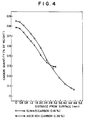
- FIG. 4 illustrates the carbon quantity included in the carburized layer of the bushings heat-treated according to the carburizing method of Table 2 and measured by an X-ray micro-analyzer.
- the effective carburized layer of the bushing produced according to the method of the present invention has substantially the same depth as that of the bushing produced according to the method of the first related art, when it is defined that a carbon quantity to be included in an effective carburized layer is 0.4 % by weight.
- the depth of the effective hardness layer of the bushing heat-treated according to the method of the first related art is 2.3-2.4 mm, when an effective hardness layer is defined as a layer having a hardness greater than Rockwell Harness C-Scale 52.3 (Vickers Hardness Scale 550) according to JIS (Japanese Industrial Standard).
- the effective hardness layer depth is slightly less than the 2.8 mm depth of the carburized layer having at least 0.4% carbon by weight.
- the depth of the effective hardness layer of the bushing heat-treated according to the method of the second related art is 3.2-3.7 mm.
- the depth of the effective hardness layer is slightly greater than the 3.1 mm depth of the carburized layer having at least 0.4% carbon by weight. This means that hardening effect due to heat treating extends beyond the carburized layer in the carburizing of a busing made from medium-carbon steel.
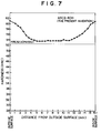
- FIG. 7 illustrating the case of the present invention.
- the entire cross-section of the wall of the bushing is hardened to a hardness greater than H RC 52.3, though the carburized layer of the bushing heat-treated according to the method of the present invention is of substantially the same order as that of bushing heat-treated according to the method of the second related art.
- FIG. 8 illustrates a comparison between a residual stress remaining in the bushing of SCM415 steel heat-treated according to the method of the first related art and a residual stress remaining in the bushing of ASCB40H steel heat-treated according to the method of the present invention.
- These residual stresses were measured by the Sack Method.
- the surface of the bushing is in a compression state and the wall core of the bushing is in a tensile state.
- the core portion of the wall of the bushing is in a slight compression state which contributes to placing the surface of the bushing in a compression state, though the surface could be in a tension state if the surface were not carburized. This compression of the surface improves the fatigue strength.
- FIG. 9 illustrates a collapse test rig.
- the test piece was prepared by cutting the bushing having the configuration shown in FIG. 3 to a length L of 30 mm. The length of the test piece was determined from the capacity of the test rig and had no other technical meaning.
- the members denoted by reference numerals 11 and 13 are compressors to compress the test piece 12 therebetween. Member 13 is stationary while member 11 compresses in a direction shown by arrow B.
- the test rigs 11 and 13 were mounted to a compression force loading machine and a load was added in the direction B to cause a crack in the test piece at positions 15.
- a collapse load was defined as a maximum load before the crack initiated.
- a collapse deformation was defined as a deformation of the test piece at the time when the maximum load was loaded.
- Table 4 illustrates the test results.
- the bushing heat-treated according to the method of the present invention has greater collapse load and deformation than those of the bushings heat-treated according to the methods of the first and second related arts. This means that the method of the present invention is preferable to the methods of the first and second related arts from the viewpoints of strength and toughness.
- FIG. 10 illustrates a test rig for testing fatigue strength.
- a test piece 17 was prepared by cutting the bushing to an appropriate length L of 20 mm. The length of 20 mm was determined by the capacity of the test rig and had no other meaning.
- the test piece 17 was supported on a supporting rig 16 and was repeatedly pushed by a pushing rig 19 in direction B. The repeating load cycles from zero stress to a stress having a stress ratio 0.05 which is 0.05% stress of the collapse stress.
- a crack initiation was detected by a probe 18 which was set at an inside surface of the test piece beneath the pushing rig 19.
- a fatigue life was evaluated from the loading repetition number at the time when a crack initiated.
- FIG. 11 shows the fatigue test results in the form of an S-N diagram where S is the crack initiation stress and N is the loading repetition number.
- the bushing heat-treated according to the method of the present invention provides substantially the same fatigue strength as those of the bushings heat-treated according to the methods of the first and second related arts. Since the first related art is used as a practical method, the method according to the present invention can also be said to be practical.
- the carburizing time can be reduced as compared with that of the first related art where a case hardening steel is used as the bushing material, to obtain the same depth of the effective carburized layer.
- the induction heating step is reduced to one half of that of the second related art.
- the hardness of a core portion of a bushing heat-treated according to the method of the first or second related art is less than the hardness defining the effective carburized layer
- the hardness of the core portion of a bushing heat-treated according to the method of the present invention is greater than the hardness limit of an effective carburized layer.
Landscapes
- Chemical & Material Sciences (AREA)
- Engineering & Computer Science (AREA)
- Mechanical Engineering (AREA)
- Materials Engineering (AREA)
- Crystallography & Structural Chemistry (AREA)
- Thermal Sciences (AREA)
- Physics & Mathematics (AREA)
- Metallurgy (AREA)
- Organic Chemistry (AREA)
- Combustion & Propulsion (AREA)
- Transportation (AREA)
- Heat Treatment Of Articles (AREA)
- Solid-Phase Diffusion Into Metallic Material Surfaces (AREA)
Description
- The present invention relates to a production method for a bushing used in a caterpillar band mounted to caterpillar vehicles and to a caterpillar band bushing and a caterpillar band shoe unit.
- A caterpillar band adapted to be mounted to caterpillar vehicles includes, as shown in FIG. 1, a
shoe 2,shoe connecting bolts 3,shoe nuts 4,rings bushings 7,dust seals 8, andpins 9 as one structural unit thereof. - The
bushing 7 used for a caterpillar band is shown in FIG. 2 in an enlarged manner. For the caterpillar band bushing, abrasion resistance is required at aninside surface 7a, anoutside surface 7b andwall portions 7c adjacent thesurfaces core portion 7d of the wall to endure a load imposed on the bushing. - To satisfy those requirements, the following production methods of a caterpillar band bushing have been proposed:
- (a) A production method as proposed in JP-A-52-3486, wherein case hardening steel (JIS (Japanese Industrial Standard): SCM415), which is a low carbon steel, is selected as the bushing material. The bushing material is carburized at portions near the surfaces thereof and is cooled in the furnace. Then, the bushing material is heated and quenched by oil, and then, the bushing material is tempered. The required hardness at the surfaces is obtained through the carburizing, and the required strength and toughness at the core portion are obtained through the quenching and tempering. This method will be called a first related art hereinafter.
- (b) A production method as proposed in JP-A-63-87338 (proposed by the present applicant and not yet published) and as shown in FIG. 3, thereof wherein
a bushingmaterial 10 of medium-carbon steel is carburized, and then the bushing material is cooled to the ambient temperature;
the bushing material is induction-heated beyond an outer carburized layer from anoutside surface 10b thereof while thebushing material 10 is rotated about anaxis 10a thereof whereby an outer effective hardened layer having a hardness greater than a specified effective hardness is formed;
the bushing material is induction-heated beyond an inner carburized layer from aninside surface 10c thereof while thebushing material 10 is rotated about theaxis 10a and the outside surface is cooled by liquid whereby an inner effective hardened layer having a hardness greater than the specified effective hardness is formed and a tempered layer having a hardness less than the specified effective hardness is formed between the inner and outer effective hardened layer; and
the bushing is tempered at low temperatures. This method will be called a second related art hereinafter. - However, the first related art is relatively expensive as it takes a long time to carburize the bushing material because the case hardening steel is a low-carbon steel. The problem with the second related art is that it requires two steps in the induction heating because the bushing material is firstly induction-heated from the outside surface thereof and then from the inside surface thereof. Therefore, the hardening time is long.
- JP-A-56-87652 discloses that a conventional steel for a track bushing can be carburized, quenched and tempered. It also discloses an allegedly superior steel composition, and mentions carburizing of this steel.
- The present invention provides a production method for a caterpillar band bushing as set out in
claim 1 and products as set out in theclaims dependent claims 2 to 6 and 8. By this method, the carburizing time can be reduced as compared with the first related art and an induction heating step may be reduced as compared with the second related art, whilst abrasion resistance, and strength and toughness at a core portion can be maintained to at least the same order as those of the first and second related arts despite the reduction of the carburizing time and the induction heating step. - The hardening may be performed through a stationary hardening method or a moving hardening method. In the stationary hardening method, the bushing material is rotated about an axis thereof within an induction heating coil, thereby heating an outside surface of the bushing material so that the entire wall cross-section is heated to a quenching temperature. An entire surface of the bushing material is then cooled by a quenching liquid so that the bushing material is evenly hardened. In the moving hardening method, the bushing material is rotated within an induction heating coil and axially moved relative to the induction heating coil. The bushing material is induction-heated from the outside surface thereof so that the entire wall cross-section is heated to the quenching temperature and then cooled by liquid flowing from a moving cooling jacket which follows the heating coil.
- The present invention thus overcomes the problems of the known methods. Since the present invention uses medium-carbon steel for the material of the bushing, the carburizing time is reduced as compared with the first related art where low carbon steel is used. Further, since the entire cross-section of the wall is induction-heated from the outside surface only, the induction heating step is reduced to about one half of the second related art where the bushing material is induction-heated first from the outside surface and then from the inside surface thereof.
- The above and other optional features and advantages of the present invention will become apparent and will be more readily appreciated from the following detailed description of the preferred exemplary embodiments of the invention taken in conjunction with the accompanying drawings, in which:
- FIG. 1 is a perspective view of a portion of a caterpillar band and the components thereof;
- FIG. 2 is a cross-sectional view of a bushing heat-treated according to the first or second related art;
- FIG. 3 is a cross-sectional view of a bushing heat-treated according to the present invention;
- FIG. 4 is a graph illustrating a relationship between a carburizing depth and a carbon quantity;
- FIG. 5 is a graph illustrating a hardness distribution in a wall of a bushing heat-treated according to the first related art;
- FIG. 6 is a graph illustrating a hardness distribution in a wall of a bushing heat-treated according to the second related art;
- FIG. 7 is a graph illustrating a hardness distribution in a wall of a bushing heat-treated according to the present invention;
- FIG. 8 is a graph illustrating a residual stress remaining in a wall of a bushing heat-treated according to the present invention and a residual stress according to the first related art;
- FIG. 9A is a front elevational view of a collapse test rig;
- FIG. 9B is a side elevational view of the test rig of FIG. 9A;
- FIG. 10A is a front elevational view of a fatigue test rig;
- FIG. 10B is a side elevational view of the test rig of FIG. 10A; and
- FIG. 11 is an S-N diagram illustrating fatigue test results of bushings heat-treated according to the present invention, and the first and second related arts.
- FIG. 3 illustrates a
bushing material 10 to which the production method of the invention is applied. In a preferred embodiment, thebushing material 10 has a length L of 212 mm, an outer diameter D1 of 88.2 mm, an inner diameter D2 of 56.0 mm, an outside surface end taper ϑ of 75°, a taper corner having a radius R1, R2 of 2 mm, and an inside surface end chamfer K of 1mm. - The bushing material to be used in the production method of the present invention should comprise steel having a medium carbon content, more particularly, having 0.3-0.5% carbon content by weight. This would include steel defined as ASCB40H according to a Japanese Automobile Industry Association Standard. The chemical composition of ASCB40H is shown in Table 1. Table 1 also includes a chemical composition of JIS: SCM415 as used in the first related art for comparison.
Table 1 Chemical Component Steel Material JIS : SCM415 (first related art) ASCB40H (the present invention) C 0.16 (wt %) 0.39 (wt %) Si 0.24 0.23 Mn 0.65 0.85 P 0.018 0.018 S 0.004 0.014 Ni 0.02 0.06 Cr 0.98 0.92 Cu 0.02 0.09 Mo 0.21 0.02 Al 0.032 0.019 Ti - 0.039 B - 0.0018 - The bushing material having the above-described composition is heat-treated according to the heat treatment specifications shown in Table 2. It is important that a carburizing time in the method of the present invention is reduced, for example, to less than six hours as compared with that in the method of the first related art and that the bushing material is induction-heated from the outside surface only. Table 2 also shows the heat-treatment specifications of the first and second related arts for comparison.
Table 2 Material Method Heat treatment Details SCM 415 first related art carburizing 1040°C * 14.3 hours cooling in a furnace quenching heating at 850°C and cooling by oil tempering 200°C ASCB40H second related art carburizing 1040°C * 5.7 hours cooling in a furnace quenching induction-hardening from the outside surface and then from the inside surface tempering 200°C ASCB40H the present invention carburizing 1040°C * 5.7 hours quenching induction-hardening the entire wall from the outside surface tempering 200°C - The specification of the high frequency induction hardening of Table 2 is shown in more detail in Table 3. Table 3 also shows the second related art for comparison.
Table 3 Specifications Second related art The present invention Heating From outside surface From inside surface From outside surface only Frequency (Khz) 3 10 1 Output (Kw) 50 70 70 Heating method moving heating moving heating stationary heating Moving speed (m/sec) 2.3 4.5 - Heating time (sec) - - 96 Cooling moving cooling moving cooling stationary cooling in liquid Coolant water soluble coolant water soluble coolant water - The bushing materials having the the chemical compositions shown in Table 1 were heat-treated according to the specifications shown in Table 2 and Table 3. The bushing material which has been heat-treated will hereinafter be called a bushing.
- The heat-treatment results, that is, the carburized layer depths and cross-section hardnesses of the bushings heat-treated according to the above-described specifications will be explained in detail below.
- FIG. 4 illustrates the carbon quantity included in the carburized layer of the bushings heat-treated according to the carburizing method of Table 2 and measured by an X-ray micro-analyzer. As seen in FIG. 4, the effective carburized layer of the bushing produced according to the method of the present invention has substantially the same depth as that of the bushing produced according to the method of the first related art, when it is defined that a carbon quantity to be included in an effective carburized layer is 0.4 % by weight.
- As seen in Fig. 5, the depth of the effective hardness layer of the bushing heat-treated according to the method of the first related art is 2.3-2.4 mm, when an effective hardness layer is defined as a layer having a hardness greater than Rockwell Harness C-Scale 52.3 (Vickers Hardness Scale 550) according to JIS (Japanese Industrial Standard). The effective hardness layer depth is slightly less than the 2.8 mm depth of the carburized layer having at least 0.4% carbon by weight.
- As seen in FIG. 6, the depth of the effective hardness layer of the bushing heat-treated according to the method of the second related art is 3.2-3.7 mm. The depth of the effective hardness layer is slightly greater than the 3.1 mm depth of the carburized layer having at least 0.4% carbon by weight. This means that hardening effect due to heat treating extends beyond the carburized layer in the carburizing of a busing made from medium-carbon steel. The same effect can be seen in FIG. 7 illustrating the case of the present invention.
- As see in FIG. 7, the entire cross-section of the wall of the bushing is hardened to a hardness greater than HRC 52.3, though the carburized layer of the bushing heat-treated according to the method of the present invention is of substantially the same order as that of bushing heat-treated according to the method of the second related art.
- FIG. 8 illustrates a comparison between a residual stress remaining in the bushing of SCM415 steel heat-treated according to the method of the first related art and a residual stress remaining in the bushing of ASCB40H steel heat-treated according to the method of the present invention. These residual stresses were measured by the Sack Method. In the case of case hardening steel SCM415, the surface of the bushing is in a compression state and the wall core of the bushing is in a tensile state. In the case of medium-carbon steel, the core portion of the wall of the bushing is in a slight compression state which contributes to placing the surface of the bushing in a compression state, though the surface could be in a tension state if the surface were not carburized. This compression of the surface improves the fatigue strength.
- FIG. 9 illustrates a collapse test rig. In the collapse test, the test piece was prepared by cutting the bushing having the configuration shown in FIG. 3 to a length L of 30 mm. The length of the test piece was determined from the capacity of the test rig and had no other technical meaning. The members denoted by
reference numerals test piece 12 therebetween.Member 13 is stationary whilemember 11 compresses in a direction shown by arrow B. The test rigs 11 and 13 were mounted to a compression force loading machine and a load was added in the direction B to cause a crack in the test piece at positions 15. A collapse load was defined as a maximum load before the crack initiated. A collapse deformation was defined as a deformation of the test piece at the time when the maximum load was loaded. Table 4 illustrates the test results.Table 4 Test piece Collapse load Collapse deformation SCM 415 first related art 23.0 (ton) 1.88 (mm) ASCB40H second related art 25.1 1.89 ASCB40H the present invention 27.4 2.51 - As seen in Table 4, the bushing heat-treated according to the method of the present invention has greater collapse load and deformation than those of the bushings heat-treated according to the methods of the first and second related arts. This means that the method of the present invention is preferable to the methods of the first and second related arts from the viewpoints of strength and toughness.
- FIG. 10 illustrates a test rig for testing fatigue strength. In the fatigue test, a
test piece 17 was prepared by cutting the bushing to an appropriate length L of 20 mm. The length of 20 mm was determined by the capacity of the test rig and had no other meaning. Thetest piece 17 was supported on a supportingrig 16 and was repeatedly pushed by a pushingrig 19 in direction B. The repeating load cycles from zero stress to a stress having a stress ratio 0.05 which is 0.05% stress of the collapse stress. A crack initiation was detected by aprobe 18 which was set at an inside surface of the test piece beneath the pushingrig 19. A fatigue life was evaluated from the loading repetition number at the time when a crack initiated. - FIG. 11 shows the fatigue test results in the form of an S-N diagram where S is the crack initiation stress and N is the loading repetition number. As seen in FIG. 11, the bushing heat-treated according to the method of the present invention provides substantially the same fatigue strength as those of the bushings heat-treated according to the methods of the first and second related arts. Since the first related art is used as a practical method, the method according to the present invention can also be said to be practical.
- Several advantages can be obtained by use of the present invention.
- First, because medium carbon steel (0.3-0.5% carbon content by weight) is selected as the bushing material, the carburizing time can be reduced as compared with that of the first related art where a case hardening steel is used as the bushing material, to obtain the same depth of the effective carburized layer.
- Second, because induction heating is performed from an outside surface of a bushing material only and an entire wall cross-section is heated, the induction heating step is reduced to one half of that of the second related art.
- Third, despite the carburizing time and induction heating step reduction, strength and toughness of the bushing are maintained generally equal to or greater than those of the bushings heat-treated according to the methods of the first and second related arts.
- Fourth, though the hardness of a core portion of a bushing heat-treated according to the method of the first or second related art is less than the hardness defining the effective carburized layer, the hardness of the core portion of a bushing heat-treated according to the method of the present invention is greater than the hardness limit of an effective carburized layer. As a result, abrasion resistance of the bushing produced according to the method of the present invention is conspicuously improved as compared with the bushings produced according to the methods of the first and second related arts.
Claims (9)
- A production method for a caterpillar band bushing comprising the steps of:
carburizing a bushing material (10) of medium-carbon steel;
cooling the bushing material (10) to an ambient temperature;
induction-heating the bushing material (10) from an outside surface (10b) of the bushing material only so that an entire cross-section of a wall of the bushing material (10) is heated;
quenching the bushing material (10) by cooling; and
tempering the bushing material (10);
wherein the quenching and tempering is performed so that a compression residual stress remains at a core portion of a wall of the bushing material (10) as well as at surfaces of the bushing material (10). - The method according to claim 1, wherein the steel used for the bushing material (10) includes a carbon content of 0.3-0.5% by weight.
- The method according to claim 1 or 2, wherein the carburizing is performed for less than 6 hours.
- The method according to any one of claims 1 to 3, wherein the carburizing is performed so that a surface adjacent portion of a wall of the bushing material (10) is hardened to a hardness greater than HRC 52.3.
- The method according to any one of claims 1 to 4 wherein the tempering is performed at temperatures less than 300°C.
- The method according to any one of claims 1 to 5 wherein the quenching and tempering is performed so that an entire cross-section of the bushing material (10) is hardened to a hardness greater than HRC 52.3.
- A caterpillar band bushing having a hardness greater than HRC 52.3 through its whole cross-section.
- A caterpillar band shoe unit having at least one bushing produced by a method according to any one of claims 1 to 6 or according to claim 7.
- A caterpillar band having at least one shoe unit according to claim 8.
Applications Claiming Priority (2)
| Application Number | Priority Date | Filing Date | Title |
|---|---|---|---|
| JP320420/88 | 1988-12-21 | ||
| JP63320420A JPH02169375A (en) | 1988-12-21 | 1988-12-21 | Crawler bushing and manufacture thereof |
Publications (3)
| Publication Number | Publication Date |
|---|---|
| EP0375392A2 EP0375392A2 (en) | 1990-06-27 |
| EP0375392A3 EP0375392A3 (en) | 1991-08-21 |
| EP0375392B1 true EP0375392B1 (en) | 1994-06-01 |
Family
ID=18121259
Family Applications (1)
| Application Number | Title | Priority Date | Filing Date |
|---|---|---|---|
| EP89313348A Expired - Lifetime EP0375392B1 (en) | 1988-12-21 | 1989-12-20 | Production method for a caterpillar band bushing |
Country Status (5)
| Country | Link |
|---|---|
| US (1) | US5032192A (en) |
| EP (1) | EP0375392B1 (en) |
| JP (1) | JPH02169375A (en) |
| KR (1) | KR930004474B1 (en) |
| DE (1) | DE68915719T2 (en) |
Families Citing this family (9)
| Publication number | Priority date | Publication date | Assignee | Title |
|---|---|---|---|---|
| US5264053A (en) * | 1990-03-31 | 1993-11-23 | Topy Kogyo Kabushiki Kaisha | Production method for a vehicular endless track bushing |
| IT1288690B1 (en) * | 1996-11-14 | 1998-09-23 | Bruno Girardello | PROCEDURE FOR THE HEAT TREATMENT OF BUSHINGS ESPECIALLY FOR TRACKED AND SIMILAR VEHICLES |
| DE20116978U1 (en) * | 2001-10-16 | 2003-02-27 | Joh. Winklhofer & Söhne GmbH und Co KG, 81369 München | articulated chain |
| US8613486B2 (en) | 2009-11-09 | 2013-12-24 | Caterpillar Inc. | Bushing for a track-type undercarriage |
| CN103540716A (en) * | 2013-09-22 | 2014-01-29 | 徐州徐工铁路装备有限公司 | Processing method of tread thermal treatment for caterpillar link |
| JP6730920B2 (en) | 2016-12-28 | 2020-07-29 | 株式会社小松製作所 | Crawler belt bearing bush and method of manufacturing the same |
| US10287648B2 (en) | 2017-05-05 | 2019-05-14 | Caterpillar Inc. | Track bushing |
| US11618516B2 (en) * | 2019-09-26 | 2023-04-04 | Caterpillar Inc. | High carbon steel track bushing |
| US20230024360A1 (en) * | 2021-07-22 | 2023-01-26 | Caterpillar Inc. | Anti-backbending idler |
Family Cites Families (6)
| Publication number | Priority date | Publication date | Assignee | Title |
|---|---|---|---|---|
| DE874009C (en) * | 1944-10-28 | 1953-04-20 | Deutsche Edelstahlwerke Ag | Process for the heat treatment of workpieces made of structural steel |
| US3227586A (en) * | 1963-08-19 | 1966-01-04 | Caterpillar Tractor Co | Track pin bushing |
| JPS5234806A (en) * | 1975-09-09 | 1977-03-17 | Dainippon Toryo Kk | Jet printing method |
| IT1171606B (en) * | 1981-10-23 | 1987-06-10 | Italtractor | PROCESS FOR HEAT TREATMENT OF CEMENTATION AT HIGH TEMPERATURE WITH CEMENTING ATMOSPHERE PRODUCED IN SITU DIRECT HARDENING AT THE ENDS OF TOTAL DISTENSION OF BUSHINGS FOR TRACTOR CATALOGS OR TRACKED VEHICLES |
| JPS63109119A (en) * | 1986-10-28 | 1988-05-13 | Topy Ind Ltd | Method for heat treatment of caterpillar bush |
| JPH01259129A (en) * | 1988-04-11 | 1989-10-16 | Topy Ind Ltd | Bushing for track containing carbon at about middle ratio and production thereof |
-
1988
- 1988-12-21 JP JP63320420A patent/JPH02169375A/en active Pending
-
1989
- 1989-12-20 DE DE68915719T patent/DE68915719T2/en not_active Expired - Lifetime
- 1989-12-20 EP EP89313348A patent/EP0375392B1/en not_active Expired - Lifetime
- 1989-12-20 US US07/454,004 patent/US5032192A/en not_active Expired - Lifetime
- 1989-12-21 KR KR1019890019102A patent/KR930004474B1/en not_active Expired - Fee Related
Also Published As
| Publication number | Publication date |
|---|---|
| DE68915719T2 (en) | 1994-11-24 |
| DE68915719D1 (en) | 1994-07-07 |
| KR930004474B1 (en) | 1993-05-27 |
| EP0375392A2 (en) | 1990-06-27 |
| EP0375392A3 (en) | 1991-08-21 |
| JPH02169375A (en) | 1990-06-29 |
| KR900009379A (en) | 1990-07-04 |
| US5032192A (en) | 1991-07-16 |
Similar Documents
| Publication | Publication Date | Title |
|---|---|---|
| Chandler | Heat treater's guide: practices and procedures for irons and steels | |
| EP0912769B1 (en) | Induction hardened microalloy steel having enhanced fatigue strength properties | |
| KR100520701B1 (en) | Method of production of surface densified powder metal components | |
| EP0600421A1 (en) | Low alloy sintered steel and method of preparing the same | |
| WO2001042524A2 (en) | Low carbon, low chromium carburizing high speed steels | |
| EP0375392A2 (en) | Production method for a caterpillar band bushing | |
| EP0332284B1 (en) | Low grade material axle shaft | |
| EP0455346B1 (en) | Production method for a vehicular endless track bushing | |
| JP5642386B2 (en) | High carbon surface densified sintered steel product and its production method | |
| EP0722796A1 (en) | Process for producing heat-treated sintered iron alloy part | |
| JP2001206002A (en) | Axle for railway vehicle and manufacturing method thereof | |
| US5049207A (en) | Heat treatment process for bushing used in track of endless track tractor | |
| US4895700A (en) | Low grade material axle shaft | |
| JP3351860B2 (en) | Crawler track bushing and method of manufacturing the same | |
| US5264053A (en) | Production method for a vehicular endless track bushing | |
| EP0356615B1 (en) | Piston ring material and piston ring | |
| JPH0578746A (en) | Manufacture of bushing for crawler | |
| EP1098011A1 (en) | An air hardenable low to medium carbon steel composition | |
| EP0339152B1 (en) | Heat treatment process for bushing used in track of endless track tractor | |
| US6391124B1 (en) | Non-heat treated, soft-nitrided steel parts | |
| JP5424298B2 (en) | Heat treatment method for cylindrical parts | |
| JPH10204534A (en) | Crawler track bush and method of manufacturing the same | |
| JPS61149462A (en) | Cored steel for of rock drill | |
| JP2021154328A (en) | Forging materials, forging members and their manufacturing methods | |
| JPS627802A (en) | Composite ring and its manufacturing method |
Legal Events
| Date | Code | Title | Description |
|---|---|---|---|
| PUAI | Public reference made under article 153(3) epc to a published international application that has entered the european phase |
Free format text: ORIGINAL CODE: 0009012 |
|
| 17P | Request for examination filed |
Effective date: 19900208 |
|
| AK | Designated contracting states |
Kind code of ref document: A2 Designated state(s): DE FR GB IT |
|
| PUAL | Search report despatched |
Free format text: ORIGINAL CODE: 0009013 |
|
| AK | Designated contracting states |
Kind code of ref document: A3 Designated state(s): DE FR GB IT |
|
| 17Q | First examination report despatched |
Effective date: 19921120 |
|
| GRAA | (expected) grant |
Free format text: ORIGINAL CODE: 0009210 |
|
| AK | Designated contracting states |
Kind code of ref document: B1 Designated state(s): DE FR GB IT |
|
| REF | Corresponds to: |
Ref document number: 68915719 Country of ref document: DE Date of ref document: 19940707 |
|
| ITF | It: translation for a ep patent filed | ||
| ET | Fr: translation filed | ||
| PLBE | No opposition filed within time limit |
Free format text: ORIGINAL CODE: 0009261 |
|
| STAA | Information on the status of an ep patent application or granted ep patent |
Free format text: STATUS: NO OPPOSITION FILED WITHIN TIME LIMIT |
|
| 26N | No opposition filed | ||
| REG | Reference to a national code |
Ref country code: GB Ref legal event code: IF02 |
|
| PGFP | Annual fee paid to national office [announced via postgrant information from national office to epo] |
Ref country code: FR Payment date: 20081222 Year of fee payment: 20 |
|
| PGFP | Annual fee paid to national office [announced via postgrant information from national office to epo] |
Ref country code: DE Payment date: 20081223 Year of fee payment: 20 |
|
| PGFP | Annual fee paid to national office [announced via postgrant information from national office to epo] |
Ref country code: GB Payment date: 20081219 Year of fee payment: 20 |
|
| PGFP | Annual fee paid to national office [announced via postgrant information from national office to epo] |
Ref country code: IT Payment date: 20081230 Year of fee payment: 20 |
|
| REG | Reference to a national code |
Ref country code: GB Ref legal event code: PE20 Expiry date: 20091219 |
|
| PG25 | Lapsed in a contracting state [announced via postgrant information from national office to epo] |
Ref country code: GB Free format text: LAPSE BECAUSE OF EXPIRATION OF PROTECTION Effective date: 20091219 |