EP0374245B1 - Fabrics for protective clothing, processes for making them - Google Patents
Fabrics for protective clothing, processes for making them Download PDFInfo
- Publication number
- EP0374245B1 EP0374245B1 EP19890908082 EP89908082A EP0374245B1 EP 0374245 B1 EP0374245 B1 EP 0374245B1 EP 19890908082 EP19890908082 EP 19890908082 EP 89908082 A EP89908082 A EP 89908082A EP 0374245 B1 EP0374245 B1 EP 0374245B1
- Authority
- EP
- European Patent Office
- Prior art keywords
- scaffold material
- barrier
- coating
- polyurethane
- sample
- Prior art date
- Legal status (The legal status is an assumption and is not a legal conclusion. Google has not performed a legal analysis and makes no representation as to the accuracy of the status listed.)
- Expired - Lifetime
Links
- 238000000034 method Methods 0.000 title claims description 18
- 239000004744 fabric Substances 0.000 title claims description 16
- 230000001681 protective effect Effects 0.000 title description 4
- 230000008569 process Effects 0.000 title description 2
- 239000000463 material Substances 0.000 claims abstract description 44
- 239000000758 substrate Substances 0.000 claims abstract description 38
- 238000000576 coating method Methods 0.000 claims abstract description 32
- 229920002635 polyurethane Polymers 0.000 claims abstract description 30
- 239000004814 polyurethane Substances 0.000 claims abstract description 30
- 239000011248 coating agent Substances 0.000 claims abstract description 25
- 239000011800 void material Substances 0.000 claims abstract description 9
- 230000005540 biological transmission Effects 0.000 claims description 10
- 229920001730 Moisture cure polyurethane Polymers 0.000 claims description 2
- 239000011148 porous material Substances 0.000 claims description 2
- 230000004888 barrier function Effects 0.000 abstract description 48
- 241000700605 Viruses Species 0.000 abstract description 21
- 241000894006 Bacteria Species 0.000 abstract description 11
- 238000012360 testing method Methods 0.000 description 41
- 239000000047 product Substances 0.000 description 39
- XLYOFNOQVPJJNP-UHFFFAOYSA-N water Chemical compound O XLYOFNOQVPJJNP-UHFFFAOYSA-N 0.000 description 33
- 239000007788 liquid Substances 0.000 description 11
- -1 polyethylene Polymers 0.000 description 11
- 229920000728 polyester Polymers 0.000 description 10
- HEMHJVSKTPXQMS-UHFFFAOYSA-M Sodium hydroxide Chemical compound [OH-].[Na+] HEMHJVSKTPXQMS-UHFFFAOYSA-M 0.000 description 9
- 230000035699 permeability Effects 0.000 description 9
- 244000005700 microbiome Species 0.000 description 8
- 239000000725 suspension Substances 0.000 description 8
- 229920001817 Agar Polymers 0.000 description 7
- 239000008272 agar Substances 0.000 description 7
- 229920001343 polytetrafluoroethylene Polymers 0.000 description 7
- 239000004810 polytetrafluoroethylene Substances 0.000 description 7
- 150000003077 polyols Chemical class 0.000 description 6
- 239000000243 solution Substances 0.000 description 6
- 239000012137 tryptone Substances 0.000 description 6
- 239000004970 Chain extender Substances 0.000 description 5
- 238000009792 diffusion process Methods 0.000 description 5
- 229920005862 polyol Polymers 0.000 description 5
- 229920001131 Pulp (paper) Polymers 0.000 description 4
- FAPWRFPIFSIZLT-UHFFFAOYSA-M Sodium chloride Chemical compound [Na+].[Cl-] FAPWRFPIFSIZLT-UHFFFAOYSA-M 0.000 description 4
- 239000007795 chemical reaction product Substances 0.000 description 4
- 239000012528 membrane Substances 0.000 description 4
- 125000006353 oxyethylene group Chemical group 0.000 description 4
- 229920000098 polyolefin Polymers 0.000 description 4
- 230000003612 virological effect Effects 0.000 description 4
- VYZAMTAEIAYCRO-UHFFFAOYSA-N Chromium Chemical compound [Cr] VYZAMTAEIAYCRO-UHFFFAOYSA-N 0.000 description 3
- 239000004698 Polyethylene Substances 0.000 description 3
- 239000004743 Polypropylene Substances 0.000 description 3
- 238000011109 contamination Methods 0.000 description 3
- 239000012530 fluid Substances 0.000 description 3
- 239000012948 isocyanate Substances 0.000 description 3
- 150000002513 isocyanates Chemical class 0.000 description 3
- 239000000203 mixture Substances 0.000 description 3
- 229920000573 polyethylene Polymers 0.000 description 3
- 229920000642 polymer Polymers 0.000 description 3
- 229920001155 polypropylene Polymers 0.000 description 3
- 229920005749 polyurethane resin Polymers 0.000 description 3
- 239000008213 purified water Substances 0.000 description 3
- 239000005871 repellent Substances 0.000 description 3
- 239000012266 salt solution Substances 0.000 description 3
- 230000032258 transport Effects 0.000 description 3
- 229920000742 Cotton Polymers 0.000 description 2
- LYCAIKOWRPUZTN-UHFFFAOYSA-N Ethylene glycol Chemical compound OCCO LYCAIKOWRPUZTN-UHFFFAOYSA-N 0.000 description 2
- WQZGKKKJIJFFOK-GASJEMHNSA-N Glucose Natural products OC[C@H]1OC(O)[C@H](O)[C@@H](O)[C@@H]1O WQZGKKKJIJFFOK-GASJEMHNSA-N 0.000 description 2
- 229920003171 Poly (ethylene oxide) Polymers 0.000 description 2
- 230000001580 bacterial effect Effects 0.000 description 2
- 230000001588 bifunctional effect Effects 0.000 description 2
- 238000010790 dilution Methods 0.000 description 2
- 239000012895 dilution Substances 0.000 description 2
- 230000000694 effects Effects 0.000 description 2
- 239000008103 glucose Substances 0.000 description 2
- 239000004615 ingredient Substances 0.000 description 2
- 239000002245 particle Substances 0.000 description 2
- 238000007747 plating Methods 0.000 description 2
- 229920001228 polyisocyanate Polymers 0.000 description 2
- 239000005056 polyisocyanate Substances 0.000 description 2
- 229920003225 polyurethane elastomer Polymers 0.000 description 2
- SCVFZCLFOSHCOH-UHFFFAOYSA-M potassium acetate Chemical compound [K+].CC([O-])=O SCVFZCLFOSHCOH-UHFFFAOYSA-M 0.000 description 2
- 230000005855 radiation Effects 0.000 description 2
- 230000002940 repellent Effects 0.000 description 2
- 229920006395 saturated elastomer Polymers 0.000 description 2
- 239000011780 sodium chloride Substances 0.000 description 2
- 239000001509 sodium citrate Substances 0.000 description 2
- NLJMYIDDQXHKNR-UHFFFAOYSA-K sodium citrate Chemical compound O.O.[Na+].[Na+].[Na+].[O-]C(=O)CC(O)(CC([O-])=O)C([O-])=O NLJMYIDDQXHKNR-UHFFFAOYSA-K 0.000 description 2
- 230000001954 sterilising effect Effects 0.000 description 2
- 238000004659 sterilization and disinfection Methods 0.000 description 2
- 239000000126 substance Substances 0.000 description 2
- 238000010998 test method Methods 0.000 description 2
- WTPYFJNYAMXZJG-UHFFFAOYSA-N 2-[4-(2-hydroxyethoxy)phenoxy]ethanol Chemical compound OCCOC1=CC=C(OCCO)C=C1 WTPYFJNYAMXZJG-UHFFFAOYSA-N 0.000 description 1
- UXVMQQNJUSDDNG-UHFFFAOYSA-L Calcium chloride Chemical compound [Cl-].[Cl-].[Ca+2] UXVMQQNJUSDDNG-UHFFFAOYSA-L 0.000 description 1
- 241000588724 Escherichia coli Species 0.000 description 1
- 229920000544 Gore-Tex Polymers 0.000 description 1
- 241000725303 Human immunodeficiency virus Species 0.000 description 1
- 206010021639 Incontinence Diseases 0.000 description 1
- 241000045365 Microporus <basidiomycete fungus> Species 0.000 description 1
- 239000004677 Nylon Substances 0.000 description 1
- 235000010627 Phaseolus vulgaris Nutrition 0.000 description 1
- 244000046052 Phaseolus vulgaris Species 0.000 description 1
- 239000004721 Polyphenylene oxide Substances 0.000 description 1
- 239000007864 aqueous solution Substances 0.000 description 1
- 239000010425 asbestos Substances 0.000 description 1
- 238000003556 assay Methods 0.000 description 1
- 230000008901 benefit Effects 0.000 description 1
- 210000004369 blood Anatomy 0.000 description 1
- 239000008280 blood Substances 0.000 description 1
- 210000001124 body fluid Anatomy 0.000 description 1
- 239000010839 body fluid Substances 0.000 description 1
- 239000001110 calcium chloride Substances 0.000 description 1
- 235000011148 calcium chloride Nutrition 0.000 description 1
- 229910001628 calcium chloride Inorganic materials 0.000 description 1
- 230000001332 colony forming effect Effects 0.000 description 1
- 238000010276 construction Methods 0.000 description 1
- 238000001816 cooling Methods 0.000 description 1
- 230000007812 deficiency Effects 0.000 description 1
- 125000005442 diisocyanate group Chemical group 0.000 description 1
- 239000012153 distilled water Substances 0.000 description 1
- 229920001971 elastomer Polymers 0.000 description 1
- 238000005516 engineering process Methods 0.000 description 1
- RTZKZFJDLAIYFH-UHFFFAOYSA-N ether Substances CCOCC RTZKZFJDLAIYFH-UHFFFAOYSA-N 0.000 description 1
- 230000001747 exhibiting effect Effects 0.000 description 1
- 229920000295 expanded polytetrafluoroethylene Polymers 0.000 description 1
- 239000000835 fiber Substances 0.000 description 1
- 238000007667 floating Methods 0.000 description 1
- 230000004907 flux Effects 0.000 description 1
- 230000004313 glare Effects 0.000 description 1
- 239000012943 hotmelt Substances 0.000 description 1
- 230000002706 hydrostatic effect Effects 0.000 description 1
- WGCNASOHLSPBMP-UHFFFAOYSA-N hydroxyacetaldehyde Natural products OCC=O WGCNASOHLSPBMP-UHFFFAOYSA-N 0.000 description 1
- 238000011534 incubation Methods 0.000 description 1
- IQPQWNKOIGAROB-UHFFFAOYSA-N isocyanate group Chemical group [N-]=C=O IQPQWNKOIGAROB-UHFFFAOYSA-N 0.000 description 1
- 239000007791 liquid phase Substances 0.000 description 1
- 238000004519 manufacturing process Methods 0.000 description 1
- 230000007246 mechanism Effects 0.000 description 1
- 239000000155 melt Substances 0.000 description 1
- 239000004745 nonwoven fabric Substances 0.000 description 1
- 229920001778 nylon Polymers 0.000 description 1
- 239000013618 particulate matter Substances 0.000 description 1
- 230000000149 penetrating effect Effects 0.000 description 1
- 230000035515 penetration Effects 0.000 description 1
- 230000002572 peristaltic effect Effects 0.000 description 1
- 239000012466 permeate Substances 0.000 description 1
- 238000005191 phase separation Methods 0.000 description 1
- 229920000570 polyether Polymers 0.000 description 1
- 229920001296 polysiloxane Polymers 0.000 description 1
- 235000011056 potassium acetate Nutrition 0.000 description 1
- 230000002028 premature Effects 0.000 description 1
- 238000002360 preparation method Methods 0.000 description 1
- 238000011002 quantification Methods 0.000 description 1
- 239000000376 reactant Substances 0.000 description 1
- 230000003134 recirculating effect Effects 0.000 description 1
- 230000001105 regulatory effect Effects 0.000 description 1
- 230000002787 reinforcement Effects 0.000 description 1
- 230000003014 reinforcing effect Effects 0.000 description 1
- 230000003252 repetitive effect Effects 0.000 description 1
- 229920005989 resin Polymers 0.000 description 1
- 239000011347 resin Substances 0.000 description 1
- 230000000717 retained effect Effects 0.000 description 1
- 229910052895 riebeckite Inorganic materials 0.000 description 1
- 238000013207 serial dilution Methods 0.000 description 1
- 210000002966 serum Anatomy 0.000 description 1
- 229920002379 silicone rubber Polymers 0.000 description 1
- 239000004945 silicone rubber Substances 0.000 description 1
- 241000894007 species Species 0.000 description 1
- 239000008174 sterile solution Substances 0.000 description 1
- 239000004753 textile Substances 0.000 description 1
- DVKJHBMWWAPEIU-UHFFFAOYSA-N toluene 2,4-diisocyanate Chemical group CC1=CC=C(N=C=O)C=C1N=C=O DVKJHBMWWAPEIU-UHFFFAOYSA-N 0.000 description 1
- 241001515965 unidentified phage Species 0.000 description 1
- 238000005406 washing Methods 0.000 description 1
- 230000004584 weight gain Effects 0.000 description 1
- 235000019786 weight gain Nutrition 0.000 description 1
- 239000002759 woven fabric Substances 0.000 description 1
Images

Classifications
-
- B—PERFORMING OPERATIONS; TRANSPORTING
- B32—LAYERED PRODUCTS
- B32B—LAYERED PRODUCTS, i.e. PRODUCTS BUILT-UP OF STRATA OF FLAT OR NON-FLAT, e.g. CELLULAR OR HONEYCOMB, FORM
- B32B5/00—Layered products characterised by the non- homogeneity or physical structure, i.e. comprising a fibrous, filamentary, particulate or foam layer; Layered products characterised by having a layer differing constitutionally or physically in different parts
- B32B5/22—Layered products characterised by the non- homogeneity or physical structure, i.e. comprising a fibrous, filamentary, particulate or foam layer; Layered products characterised by having a layer differing constitutionally or physically in different parts characterised by the presence of two or more layers which are next to each other and are fibrous, filamentary, formed of particles or foamed
- B32B5/24—Layered products characterised by the non- homogeneity or physical structure, i.e. comprising a fibrous, filamentary, particulate or foam layer; Layered products characterised by having a layer differing constitutionally or physically in different parts characterised by the presence of two or more layers which are next to each other and are fibrous, filamentary, formed of particles or foamed one layer being a fibrous or filamentary layer
-
- A—HUMAN NECESSITIES
- A61—MEDICAL OR VETERINARY SCIENCE; HYGIENE
- A61F—FILTERS IMPLANTABLE INTO BLOOD VESSELS; PROSTHESES; DEVICES PROVIDING PATENCY TO, OR PREVENTING COLLAPSING OF, TUBULAR STRUCTURES OF THE BODY, e.g. STENTS; ORTHOPAEDIC, NURSING OR CONTRACEPTIVE DEVICES; FOMENTATION; TREATMENT OR PROTECTION OF EYES OR EARS; BANDAGES, DRESSINGS OR ABSORBENT PADS; FIRST-AID KITS
- A61F13/00—Bandages or dressings; Absorbent pads
- A61F13/01—Non-adhesive bandages or dressings
- A61F13/01008—Non-adhesive bandages or dressings characterised by the material
-
- A—HUMAN NECESSITIES
- A41—WEARING APPAREL
- A41D—OUTERWEAR; PROTECTIVE GARMENTS; ACCESSORIES
- A41D31/00—Materials specially adapted for outerwear
- A41D31/04—Materials specially adapted for outerwear characterised by special function or use
- A41D31/30—Antimicrobial, e.g. antibacterial
- A41D31/305—Antimicrobial, e.g. antibacterial using layered materials
-
- B—PERFORMING OPERATIONS; TRANSPORTING
- B32—LAYERED PRODUCTS
- B32B—LAYERED PRODUCTS, i.e. PRODUCTS BUILT-UP OF STRATA OF FLAT OR NON-FLAT, e.g. CELLULAR OR HONEYCOMB, FORM
- B32B5/00—Layered products characterised by the non- homogeneity or physical structure, i.e. comprising a fibrous, filamentary, particulate or foam layer; Layered products characterised by having a layer differing constitutionally or physically in different parts
- B32B5/22—Layered products characterised by the non- homogeneity or physical structure, i.e. comprising a fibrous, filamentary, particulate or foam layer; Layered products characterised by having a layer differing constitutionally or physically in different parts characterised by the presence of two or more layers which are next to each other and are fibrous, filamentary, formed of particles or foamed
-
- D—TEXTILES; PAPER
- D06—TREATMENT OF TEXTILES OR THE LIKE; LAUNDERING; FLEXIBLE MATERIALS NOT OTHERWISE PROVIDED FOR
- D06N—WALL, FLOOR, OR LIKE COVERING MATERIALS, e.g. LINOLEUM, OILCLOTH, ARTIFICIAL LEATHER, ROOFING FELT, CONSISTING OF A FIBROUS WEB COATED WITH A LAYER OF MACROMOLECULAR MATERIAL; FLEXIBLE SHEET MATERIAL NOT OTHERWISE PROVIDED FOR
- D06N3/00—Artificial leather, oilcloth or other material obtained by covering fibrous webs with macromolecular material, e.g. resins, rubber or derivatives thereof
- D06N3/04—Artificial leather, oilcloth or other material obtained by covering fibrous webs with macromolecular material, e.g. resins, rubber or derivatives thereof with macromolecular compounds obtained by reactions only involving carbon-to-carbon unsaturated bonds
- D06N3/045—Artificial leather, oilcloth or other material obtained by covering fibrous webs with macromolecular material, e.g. resins, rubber or derivatives thereof with macromolecular compounds obtained by reactions only involving carbon-to-carbon unsaturated bonds with polyolefin or polystyrene (co-)polymers
-
- D—TEXTILES; PAPER
- D06—TREATMENT OF TEXTILES OR THE LIKE; LAUNDERING; FLEXIBLE MATERIALS NOT OTHERWISE PROVIDED FOR
- D06N—WALL, FLOOR, OR LIKE COVERING MATERIALS, e.g. LINOLEUM, OILCLOTH, ARTIFICIAL LEATHER, ROOFING FELT, CONSISTING OF A FIBROUS WEB COATED WITH A LAYER OF MACROMOLECULAR MATERIAL; FLEXIBLE SHEET MATERIAL NOT OTHERWISE PROVIDED FOR
- D06N3/00—Artificial leather, oilcloth or other material obtained by covering fibrous webs with macromolecular material, e.g. resins, rubber or derivatives thereof
- D06N3/12—Artificial leather, oilcloth or other material obtained by covering fibrous webs with macromolecular material, e.g. resins, rubber or derivatives thereof with macromolecular compounds obtained otherwise than by reactions only involving carbon-to-carbon unsaturated bonds, e.g. gelatine proteins
- D06N3/14—Artificial leather, oilcloth or other material obtained by covering fibrous webs with macromolecular material, e.g. resins, rubber or derivatives thereof with macromolecular compounds obtained otherwise than by reactions only involving carbon-to-carbon unsaturated bonds, e.g. gelatine proteins with polyurethanes
-
- D—TEXTILES; PAPER
- D06—TREATMENT OF TEXTILES OR THE LIKE; LAUNDERING; FLEXIBLE MATERIALS NOT OTHERWISE PROVIDED FOR
- D06N—WALL, FLOOR, OR LIKE COVERING MATERIALS, e.g. LINOLEUM, OILCLOTH, ARTIFICIAL LEATHER, ROOFING FELT, CONSISTING OF A FIBROUS WEB COATED WITH A LAYER OF MACROMOLECULAR MATERIAL; FLEXIBLE SHEET MATERIAL NOT OTHERWISE PROVIDED FOR
- D06N3/00—Artificial leather, oilcloth or other material obtained by covering fibrous webs with macromolecular material, e.g. resins, rubber or derivatives thereof
- D06N3/18—Artificial leather, oilcloth or other material obtained by covering fibrous webs with macromolecular material, e.g. resins, rubber or derivatives thereof with two layers of different macromolecular materials
- D06N3/183—Artificial leather, oilcloth or other material obtained by covering fibrous webs with macromolecular material, e.g. resins, rubber or derivatives thereof with two layers of different macromolecular materials the layers are one next to the other
-
- A—HUMAN NECESSITIES
- A61—MEDICAL OR VETERINARY SCIENCE; HYGIENE
- A61F—FILTERS IMPLANTABLE INTO BLOOD VESSELS; PROSTHESES; DEVICES PROVIDING PATENCY TO, OR PREVENTING COLLAPSING OF, TUBULAR STRUCTURES OF THE BODY, e.g. STENTS; ORTHOPAEDIC, NURSING OR CONTRACEPTIVE DEVICES; FOMENTATION; TREATMENT OR PROTECTION OF EYES OR EARS; BANDAGES, DRESSINGS OR ABSORBENT PADS; FIRST-AID KITS
- A61F13/00—Bandages or dressings; Absorbent pads
- A61F2013/00089—Wound bandages
- A61F2013/00246—Wound bandages in a special way pervious to air or vapours
- A61F2013/00263—Wound bandages in a special way pervious to air or vapours vapour permeability >500 g/m2/24h
-
- A—HUMAN NECESSITIES
- A61—MEDICAL OR VETERINARY SCIENCE; HYGIENE
- A61F—FILTERS IMPLANTABLE INTO BLOOD VESSELS; PROSTHESES; DEVICES PROVIDING PATENCY TO, OR PREVENTING COLLAPSING OF, TUBULAR STRUCTURES OF THE BODY, e.g. STENTS; ORTHOPAEDIC, NURSING OR CONTRACEPTIVE DEVICES; FOMENTATION; TREATMENT OR PROTECTION OF EYES OR EARS; BANDAGES, DRESSINGS OR ABSORBENT PADS; FIRST-AID KITS
- A61F13/00—Bandages or dressings; Absorbent pads
- A61F2013/00089—Wound bandages
- A61F2013/00272—Wound bandages protection of the body or articulation
-
- A—HUMAN NECESSITIES
- A61—MEDICAL OR VETERINARY SCIENCE; HYGIENE
- A61F—FILTERS IMPLANTABLE INTO BLOOD VESSELS; PROSTHESES; DEVICES PROVIDING PATENCY TO, OR PREVENTING COLLAPSING OF, TUBULAR STRUCTURES OF THE BODY, e.g. STENTS; ORTHOPAEDIC, NURSING OR CONTRACEPTIVE DEVICES; FOMENTATION; TREATMENT OR PROTECTION OF EYES OR EARS; BANDAGES, DRESSINGS OR ABSORBENT PADS; FIRST-AID KITS
- A61F13/00—Bandages or dressings; Absorbent pads
- A61F2013/00361—Plasters
- A61F2013/00727—Plasters means for wound humidity control
- A61F2013/00731—Plasters means for wound humidity control with absorbing pads
- A61F2013/00744—Plasters means for wound humidity control with absorbing pads containing non-woven
-
- A—HUMAN NECESSITIES
- A61—MEDICAL OR VETERINARY SCIENCE; HYGIENE
- A61F—FILTERS IMPLANTABLE INTO BLOOD VESSELS; PROSTHESES; DEVICES PROVIDING PATENCY TO, OR PREVENTING COLLAPSING OF, TUBULAR STRUCTURES OF THE BODY, e.g. STENTS; ORTHOPAEDIC, NURSING OR CONTRACEPTIVE DEVICES; FOMENTATION; TREATMENT OR PROTECTION OF EYES OR EARS; BANDAGES, DRESSINGS OR ABSORBENT PADS; FIRST-AID KITS
- A61F13/00—Bandages or dressings; Absorbent pads
- A61F2013/00361—Plasters
- A61F2013/00855—Plasters pervious to air or vapours
- A61F2013/00876—Plasters pervious to air or vapours vapour permeability >500 g/mg/24h
-
- B—PERFORMING OPERATIONS; TRANSPORTING
- B32—LAYERED PRODUCTS
- B32B—LAYERED PRODUCTS, i.e. PRODUCTS BUILT-UP OF STRATA OF FLAT OR NON-FLAT, e.g. CELLULAR OR HONEYCOMB, FORM
- B32B2266/00—Composition of foam
- B32B2266/02—Organic
- B32B2266/0214—Materials belonging to B32B27/00
- B32B2266/025—Polyolefin
-
- B—PERFORMING OPERATIONS; TRANSPORTING
- B32—LAYERED PRODUCTS
- B32B—LAYERED PRODUCTS, i.e. PRODUCTS BUILT-UP OF STRATA OF FLAT OR NON-FLAT, e.g. CELLULAR OR HONEYCOMB, FORM
- B32B2305/00—Condition, form or state of the layers or laminate
- B32B2305/02—Cellular or porous
- B32B2305/026—Porous
-
- B—PERFORMING OPERATIONS; TRANSPORTING
- B32—LAYERED PRODUCTS
- B32B—LAYERED PRODUCTS, i.e. PRODUCTS BUILT-UP OF STRATA OF FLAT OR NON-FLAT, e.g. CELLULAR OR HONEYCOMB, FORM
- B32B2307/00—Properties of the layers or laminate
- B32B2307/70—Other properties
- B32B2307/724—Permeability to gases, adsorption
-
- B—PERFORMING OPERATIONS; TRANSPORTING
- B32—LAYERED PRODUCTS
- B32B—LAYERED PRODUCTS, i.e. PRODUCTS BUILT-UP OF STRATA OF FLAT OR NON-FLAT, e.g. CELLULAR OR HONEYCOMB, FORM
- B32B2307/00—Properties of the layers or laminate
- B32B2307/70—Other properties
- B32B2307/726—Permeability to liquids, absorption
- B32B2307/7265—Non-permeable
-
- B—PERFORMING OPERATIONS; TRANSPORTING
- B32—LAYERED PRODUCTS
- B32B—LAYERED PRODUCTS, i.e. PRODUCTS BUILT-UP OF STRATA OF FLAT OR NON-FLAT, e.g. CELLULAR OR HONEYCOMB, FORM
- B32B2323/00—Polyalkenes
- B32B2323/04—Polyethylene
-
- B—PERFORMING OPERATIONS; TRANSPORTING
- B32—LAYERED PRODUCTS
- B32B—LAYERED PRODUCTS, i.e. PRODUCTS BUILT-UP OF STRATA OF FLAT OR NON-FLAT, e.g. CELLULAR OR HONEYCOMB, FORM
- B32B2323/00—Polyalkenes
- B32B2323/10—Polypropylene
-
- B—PERFORMING OPERATIONS; TRANSPORTING
- B32—LAYERED PRODUCTS
- B32B—LAYERED PRODUCTS, i.e. PRODUCTS BUILT-UP OF STRATA OF FLAT OR NON-FLAT, e.g. CELLULAR OR HONEYCOMB, FORM
- B32B2437/00—Clothing
-
- B—PERFORMING OPERATIONS; TRANSPORTING
- B32—LAYERED PRODUCTS
- B32B—LAYERED PRODUCTS, i.e. PRODUCTS BUILT-UP OF STRATA OF FLAT OR NON-FLAT, e.g. CELLULAR OR HONEYCOMB, FORM
- B32B2535/00—Medical equipment, e.g. bandage, prostheses or catheter
-
- B—PERFORMING OPERATIONS; TRANSPORTING
- B32—LAYERED PRODUCTS
- B32B—LAYERED PRODUCTS, i.e. PRODUCTS BUILT-UP OF STRATA OF FLAT OR NON-FLAT, e.g. CELLULAR OR HONEYCOMB, FORM
- B32B2553/00—Packaging equipment or accessories not otherwise provided for
-
- B—PERFORMING OPERATIONS; TRANSPORTING
- B32—LAYERED PRODUCTS
- B32B—LAYERED PRODUCTS, i.e. PRODUCTS BUILT-UP OF STRATA OF FLAT OR NON-FLAT, e.g. CELLULAR OR HONEYCOMB, FORM
- B32B2555/00—Personal care
- B32B2555/02—Diapers or napkins
-
- D—TEXTILES; PAPER
- D06—TREATMENT OF TEXTILES OR THE LIKE; LAUNDERING; FLEXIBLE MATERIALS NOT OTHERWISE PROVIDED FOR
- D06N—WALL, FLOOR, OR LIKE COVERING MATERIALS, e.g. LINOLEUM, OILCLOTH, ARTIFICIAL LEATHER, ROOFING FELT, CONSISTING OF A FIBROUS WEB COATED WITH A LAYER OF MACROMOLECULAR MATERIAL; FLEXIBLE SHEET MATERIAL NOT OTHERWISE PROVIDED FOR
- D06N2209/00—Properties of the materials
- D06N2209/12—Permeability or impermeability properties
- D06N2209/121—Permeability to gases, adsorption
- D06N2209/123—Breathable
-
- D—TEXTILES; PAPER
- D06—TREATMENT OF TEXTILES OR THE LIKE; LAUNDERING; FLEXIBLE MATERIALS NOT OTHERWISE PROVIDED FOR
- D06N—WALL, FLOOR, OR LIKE COVERING MATERIALS, e.g. LINOLEUM, OILCLOTH, ARTIFICIAL LEATHER, ROOFING FELT, CONSISTING OF A FIBROUS WEB COATED WITH A LAYER OF MACROMOLECULAR MATERIAL; FLEXIBLE SHEET MATERIAL NOT OTHERWISE PROVIDED FOR
- D06N2209/00—Properties of the materials
- D06N2209/14—Properties of the materials having chemical properties
- D06N2209/141—Hydrophilic
-
- D—TEXTILES; PAPER
- D06—TREATMENT OF TEXTILES OR THE LIKE; LAUNDERING; FLEXIBLE MATERIALS NOT OTHERWISE PROVIDED FOR
- D06N—WALL, FLOOR, OR LIKE COVERING MATERIALS, e.g. LINOLEUM, OILCLOTH, ARTIFICIAL LEATHER, ROOFING FELT, CONSISTING OF A FIBROUS WEB COATED WITH A LAYER OF MACROMOLECULAR MATERIAL; FLEXIBLE SHEET MATERIAL NOT OTHERWISE PROVIDED FOR
- D06N2209/00—Properties of the materials
- D06N2209/16—Properties of the materials having other properties
- D06N2209/1671—Resistance to bacteria, mildew, mould, fungi
-
- D—TEXTILES; PAPER
- D06—TREATMENT OF TEXTILES OR THE LIKE; LAUNDERING; FLEXIBLE MATERIALS NOT OTHERWISE PROVIDED FOR
- D06N—WALL, FLOOR, OR LIKE COVERING MATERIALS, e.g. LINOLEUM, OILCLOTH, ARTIFICIAL LEATHER, ROOFING FELT, CONSISTING OF A FIBROUS WEB COATED WITH A LAYER OF MACROMOLECULAR MATERIAL; FLEXIBLE SHEET MATERIAL NOT OTHERWISE PROVIDED FOR
- D06N2211/00—Specially adapted uses
- D06N2211/10—Clothing
-
- D—TEXTILES; PAPER
- D06—TREATMENT OF TEXTILES OR THE LIKE; LAUNDERING; FLEXIBLE MATERIALS NOT OTHERWISE PROVIDED FOR
- D06N—WALL, FLOOR, OR LIKE COVERING MATERIALS, e.g. LINOLEUM, OILCLOTH, ARTIFICIAL LEATHER, ROOFING FELT, CONSISTING OF A FIBROUS WEB COATED WITH A LAYER OF MACROMOLECULAR MATERIAL; FLEXIBLE SHEET MATERIAL NOT OTHERWISE PROVIDED FOR
- D06N2211/00—Specially adapted uses
- D06N2211/12—Decorative or sun protection articles
- D06N2211/24—Personal care
-
- Y—GENERAL TAGGING OF NEW TECHNOLOGICAL DEVELOPMENTS; GENERAL TAGGING OF CROSS-SECTIONAL TECHNOLOGIES SPANNING OVER SEVERAL SECTIONS OF THE IPC; TECHNICAL SUBJECTS COVERED BY FORMER USPC CROSS-REFERENCE ART COLLECTIONS [XRACs] AND DIGESTS
- Y10—TECHNICAL SUBJECTS COVERED BY FORMER USPC
- Y10T—TECHNICAL SUBJECTS COVERED BY FORMER US CLASSIFICATION
- Y10T428/00—Stock material or miscellaneous articles
- Y10T428/24—Structurally defined web or sheet [e.g., overall dimension, etc.]
- Y10T428/24802—Discontinuous or differential coating, impregnation or bond [e.g., artwork, printing, retouched photograph, etc.]
- Y10T428/2481—Discontinuous or differential coating, impregnation or bond [e.g., artwork, printing, retouched photograph, etc.] including layer of mechanically interengaged strands, strand-portions or strand-like strips
-
- Y—GENERAL TAGGING OF NEW TECHNOLOGICAL DEVELOPMENTS; GENERAL TAGGING OF CROSS-SECTIONAL TECHNOLOGIES SPANNING OVER SEVERAL SECTIONS OF THE IPC; TECHNICAL SUBJECTS COVERED BY FORMER USPC CROSS-REFERENCE ART COLLECTIONS [XRACs] AND DIGESTS
- Y10—TECHNICAL SUBJECTS COVERED BY FORMER USPC
- Y10T—TECHNICAL SUBJECTS COVERED BY FORMER US CLASSIFICATION
- Y10T428/00—Stock material or miscellaneous articles
- Y10T428/249921—Web or sheet containing structurally defined element or component
- Y10T428/249953—Composite having voids in a component [e.g., porous, cellular, etc.]
- Y10T428/249978—Voids specified as micro
- Y10T428/24998—Composite has more than two layers
-
- Y—GENERAL TAGGING OF NEW TECHNOLOGICAL DEVELOPMENTS; GENERAL TAGGING OF CROSS-SECTIONAL TECHNOLOGIES SPANNING OVER SEVERAL SECTIONS OF THE IPC; TECHNICAL SUBJECTS COVERED BY FORMER USPC CROSS-REFERENCE ART COLLECTIONS [XRACs] AND DIGESTS
- Y10—TECHNICAL SUBJECTS COVERED BY FORMER USPC
- Y10T—TECHNICAL SUBJECTS COVERED BY FORMER US CLASSIFICATION
- Y10T428/00—Stock material or miscellaneous articles
- Y10T428/31504—Composite [nonstructural laminate]
- Y10T428/3154—Of fluorinated addition polymer from unsaturated monomers
- Y10T428/31544—Addition polymer is perhalogenated
-
- Y—GENERAL TAGGING OF NEW TECHNOLOGICAL DEVELOPMENTS; GENERAL TAGGING OF CROSS-SECTIONAL TECHNOLOGIES SPANNING OVER SEVERAL SECTIONS OF THE IPC; TECHNICAL SUBJECTS COVERED BY FORMER USPC CROSS-REFERENCE ART COLLECTIONS [XRACs] AND DIGESTS
- Y10—TECHNICAL SUBJECTS COVERED BY FORMER USPC
- Y10T—TECHNICAL SUBJECTS COVERED BY FORMER US CLASSIFICATION
- Y10T428/00—Stock material or miscellaneous articles
- Y10T428/31504—Composite [nonstructural laminate]
- Y10T428/31551—Of polyamidoester [polyurethane, polyisocyanate, polycarbamate, etc.]
-
- Y—GENERAL TAGGING OF NEW TECHNOLOGICAL DEVELOPMENTS; GENERAL TAGGING OF CROSS-SECTIONAL TECHNOLOGIES SPANNING OVER SEVERAL SECTIONS OF THE IPC; TECHNICAL SUBJECTS COVERED BY FORMER USPC CROSS-REFERENCE ART COLLECTIONS [XRACs] AND DIGESTS
- Y10—TECHNICAL SUBJECTS COVERED BY FORMER USPC
- Y10T—TECHNICAL SUBJECTS COVERED BY FORMER US CLASSIFICATION
- Y10T442/00—Fabric [woven, knitted, or nonwoven textile or cloth, etc.]
- Y10T442/20—Coated or impregnated woven, knit, or nonwoven fabric which is not [a] associated with another preformed layer or fiber layer or, [b] with respect to woven and knit, characterized, respectively, by a particular or differential weave or knit, wherein the coating or impregnation is neither a foamed material nor a free metal or alloy layer
- Y10T442/2139—Coating or impregnation specified as porous or permeable to a specific substance [e.g., water vapor, air, etc.]
- Y10T442/2148—Coating or impregnation is specified as microporous but is not a foam
Definitions
- This invention relates to a method for manufacturing which more particularly provide barrier protection against microorganisms, such as bacteria and viruses, and against airborne particulate matter.
- Surgical gowns, drapes and the like protect surgically prepared areas of the skin from contamination and also protect surgeons and nurses against contamination through contact with unprepared or contaminated areas of patient's skin.
- surgical gowns should present a sterile barrier to protect patients from contamination through contact with the surgeon, and vice versa.
- Liquid imperviousness of the gown or drape is recognized as an important property in assuring that the gown or drape presents a sterile surface and acts as a barrier to the passage of bacteria or virus.
- Body liquids and other liquids can permeate through the surgical gown or drape and contact the skin of the patient.
- bacteria and viruses, such as the AIDS virus which are present on the surface of the gown or drape may be transported through the gown to the patient or the operating room personnel.
- hospital gowns desirably present a non-glare outer surface, are nonlinting, possess antistatic characteristics and, not least importantly, are comfortable to wear.
- One type of commonly used protective clothing is made from a polyolefin nonwoven substrate. While having reasonable properties for protection, garments constructed of this material are known to be very uncomfortable due to their inherent low moisture transmission characteristics, i.e their low breathability. Various attempts have been made to improve breathability of this nonwoven material. These efforts, however, result frequently in a more open structure of the nonwoven material and thus also simultaneously lower its protection value. Coatings on spun-bonded polyolefin have been employed to afford greater barrier protection to the 'open' base structure of the nonwoven. However, the already inherently low moisture transmission characteristics of the spun-bonded material are even further reduced, simultaneously reducing the comfort of garments made by use of this technology.
- Prior-filed EP-A-288,214 discloses a coated product comprising a substrate and a microporous scaffold having a void volume of greater than 40% of open interconnecting microstructure, the void being substantially filled with a chemical substance which may be a polymer.
- the present invention allows for both very desirable barrier protection characteristics while simultaneously achieving good moisture vapor transmitting characteristics; i.e. protection with comfort.
- the coated product provides a functional barrier without compromising the comfort to the wearer.
- the functional barrier provided serves as an effective barrier to microorganisms and air-borne particulates.
- a coating is applied to one side of a substrate in a particular manner to impart the desired barrier features.
- the coating is a combination of both a polymeric microporous scaffold layer and a hydrophilic polyurethane resin.
- the method of this invention comprises:
- the surface of the coated fabric has a pleasing appearance which is due to the fact that the polyurethane resin does not fill the voids of the scaffold to the extent that the resin is present on the opposite side of the scaffold.
- a second layer of untreated scaffold can be applied to that surface.
- the products of the method of this invention are continuous coatings and as such exhibit substantially no air permeability and so afford a barrier to air-borne, particulates. Furthermore, the products of this invention function as a barrier to microorganisms, such as viruses and bacteria. These barrier characteristics are achieved while the moisture vapor transmission rate (MVTR) of the coated product is only slightly lower than the MVTR of the uncoated starting substrate. Thus the product of this invention yields both protection and comfort maximizing both without compromising either. Notably, these features are also retained following gamma radiation sterilization.
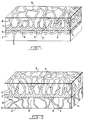
- FIGS 1 and 2 depict the construction of one embodiment of the invention.
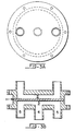
- Figures 3 and 4 depict views of a machine used to test coated fabrics for viral barrier efficiency.
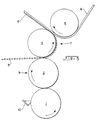
- Figure 5 is a schematic drawing of the process used in the invention.
- Figure 6 is a scanning electron microphotography of products of the invention.
- a coated product or fabric is one in which a substrate is covered continuously on a surface with one or more materials to give the substrate a property it does not possess by itself.
- the substrate used in this invention can be any fabric that has a moisture vapor transmission rate of at least 5000 gm/m2/24 hr.
- the fabric may be woven, non-woven or knitted.
- the substrate may be made of paper. It may also have the form of a scrim, mesh, or grid.
- a textile fabric such as a polyester-cotton blend, or a nonwoven material that contains wood pulp is often used as the substrate.
- the polymeric scaffold material is a microporus polymer having a microstructure of open, interconnecting voids and void volume of greater than 65%. It may preferably have a void volume greater than 70% or even 85%, for some applications.
- the scaffold material may have a thickness of less than 100 ⁇ m, preferably less than 35 ⁇ m, and most preferably less than 20 ⁇ m.
- Scaffold materials include films of microporous polyolefins, such as polytetrafluoroethylene, polypropylene, polyethylene and other microporous polymers, which possess high moisture vapor transmission rates.
- microporous polyolefins such as polytetrafluoroethylene, polypropylene, polyethylene and other microporous polymers, which possess high moisture vapor transmission rates.
- a preferred scaffold material is expanded polytetrafluoroethylene (PTFE). This material is characterized by a multiplicity of open, interconnecting voids, high strength, and stable chemical properties.
- PTFE polytetrafluoroethylene
- U. S. Patent No. 3,953,566 and 4,187,390 describes the preparation of the desirable microporous, expanded, polytetrafluoroethylene films. These films are commercially available from W. L. Gore & Associates, Inc., and are sold under the trademark GORE-TEX.
- the hydrophilic polyurethane layer selectively transports water by diffusion but does not support pressure driven liquid flow. Therefore moisture is transported, but the continuous layer precludes passage of microorganisms and air.
- the polyurethanes useful herein comprise the product of a polyol of primarily oxyethylene units and a polyisocyanate.
- the polyol moiety comprises greater than 45% by weight of polyurethane, preferably greater than 60%, most preferably greater than 70%.
- polyurethanes are those that have a backbone of polyoxyethylene which end with toluene diisocyanate groups. It has a branched polyether with at least three reactive isocyanate groups.
- Another class of polyurethanes comprise the reaction product of:
- the polyurethane in the form of its liquid phase is applied to one side of the scaffold material in a controlled amount so as to form a layer on the material and to partially infiltrate the voids of the material.
- the substrate is combined with the polyurethane side of the polyurethane/scaffold combination (coating) and subsequently caused to solidify and/or cure in a firm bond between the substrate and the coating.
- the coating method is illustrated in the following description of a four roll stack as illustrated in Figure 5.
- Metered control of polyurethane is provided for by a gravure roll, 1, and doctor blade/feed reservoir, 10.
- the polyurethane, 9, is applied in a controlled amount to the continuously moving, scaffold material, 5, in the nip between two rotating rolls, 2 and 3; one such rotating roll, 2, carrying a controlled amount of the polyurethane and the other such roll, 3, providing support so as to force the polyurethane partially into the porous structure of the scaffold material, 5.
- the coating, 7, i.e. the scaffold material and polyurethane combination
- This method can be further modified to allow for a second substrate to be brought into the backside of the coating to cause a sandwich effect, the coating being between the two substrates.
- the pressure between rolls 2 and 3 and the amount of polyurethane flow are adjusted to result in the polyurethane both coating the scaffold material surface and infiltrating the voids of the scaffold to a predetermined extent. Care is taken, however, not to completely fill the voids of the microporous scaffold.
- substrate 1 is shown as a woven fabric made of fibers 2 in Figure 1 and as a nonwoven fabric in Figure 2. Raised or elevated portions of the fabric are shown as 3.
- the polyurethane layer is shown as 4, and as seen, contacts and adheres to the substrate at raised or elevated points 3. Airspaces in the fabric are depicted as 8.
- the scaffold material is shown as 5 and the voids are shown as 6 and are partially filled with polyurethane as shown at 7.
- the coating (combination of the polyurethane and scaffold material) is attached to the substrate in an unique way.
- the coating and the substrate attach only at elevated specific points. This is contrasted against what is normally seen in the prior art, where coatings in general seems to follow the contour of the substrate and/or fill in the voids and valleys in the substrate and as such is seen to not have an overall regular thickness.
- the coating herein on a microscopic scale is seen to span between the points of contact of the substrate rather than follow the contours of the surface.
- Drape is defined as the way a fabric falls when hung in different positions. Drape is associated with flexibility and suppleness. Furthermore it is believed that it is the combination of scaffold & polyurethane that allows for such a thin hydrophilic polyurethane layer to be so continuous. It is this continuity that provides the desired functional barrier properties and the thinness that allows such high rates of water vapor transfer.
- the products of this invention also provide utility in applications where barrier control of airborne particulates are desired. For instance they find usefulness in asbestos clean-up where the worker needs to be comfortable, yet protected. Turning the protection concept around, the product also provides utility also in keeping body particulates away from sensitive material manufactured or used within a clean room.
- MVTR moisture vapor transmission rate
- Coated samples are then placed coated side down onto the surface of the floating expanded PTFE membrane.
- the cup assembly weighed to the nearest 1/1000 gm and was placed in an inverted manner onto the center of the test sample.
- the MVTR of the sample was calculated from the weight gain of the cup assembly and was expressed in grams of water per square meter of sample surface area per 24 hours.
- a second cup assembly was simultaneously weighed to within 1/1000 gm and placed onto the test sample in an inverted manner as before. The test was repeated until a steady state MVTR was observed by two repetitive MVTR values. With thin coatings (less than 0.25 mm), this generally has been found to require only one test interval to achieve steady state information within the variability of the test.
- Coated products of the present invention were tested for coating continuity using a modified Suter test apparatus, which is a low water entry pressure challenge.
- Water was forced against a sample of 10 cm diameter sealed by two rubber gaskets in a clamped arrangement.
- the sample was mounted with the coating side down against the water. It is important that a leakproof seal is formed by the clamp mechanism, gaskets and sample.
- the sample was held in place by a reinforcing scrim (e.g. open nonwoven).
- the sample was open to atmospheric conditions and was visible to the operator.
- the water pressure on the sample was increased to 6.89 kPa by a pump connected to a water reservoir, as indicated by an appropriate gauge and regulated by an in-line valve.
- test sample was at an angle and the water was recirculating to assure water contact and not air against the sample's lower surface.
- the upper surface of the sample was visually observed for a period of at least 1 minute for the appearance of any water which would be forced through the sample. Liquid water seen on the surface was interpreted as a deficiency in the continuity of the coating. A passing grade was given for no liquid water visible within 3 minutes, thus indicating a continuous coating.
- a jig, as shown in Figures 3 and 4 was designed to hold the barrier being challenged.
- the virus suspension is contained in a pressurizable reservoir.
- a second reservoir contains a tryptone broth which is pumped so the bottom of the barrier is continuously washed by the broth. The washings are returned to a holding vessel for the broth.
- the upper reservoir is filled with a virus suspension (at least 1 x 10⁸ virus particles/ml) and is pressurized. Any virus particles passing through the barrier are washed into the broth. After a set period of time, the broth is sampled for assay.
- a small icosahedral shaped bacteriophage (phi-X174) with a diameter of 27 nanometers was used.
- the suspending liquid was human serum.
- the test period was 30 minutes at 0.5 - 1 cm. of water pressure, 30 minutes at 4 cm water pressure, 30 minutes at 1.1 bar (1 psig.) and 30 minutes at (4 psi g.) 1.3 bar applied to the virus suspension reservoir. Broth samples were collected at the beginning and then at the end of each interval.
- Barrier efficiency is measured by observing the pressure at which virus breakthrough occurs up to 1.3 bar (4 psig). Any break through is judged a failure. Passing is no breakthrough at (4 psig.) 1.3 bar.
- the media used are shown below.
- Tryptone broth Bacto-tryptone 10.0 g KCl 5.0 g CaCl2 0.15 g purified water q.s. 1000 mL adjust to pH 7.3 with 2.5 N NaOH; sterilize
- Top agar Bacto-agar 6.5 g tryptone 13.0 g NaCl 8.0 g Glucose 3.0 g sodium citrate 2.0 g purified water q.s. 1000 mL Add each ingredient in order. Adjust to pH 7.5 with 2.5 N NaOH or HCl autoclave.
- Bottom agar Bacto-agar 10.0 g tryptone 13.0 g NaCl 8.0 g Glucose 1.3 g sodium citrate 2.0 g purified water q.s. 1000 mL Add each ingredient in order. Adjust to pH 7.5 with 2.5 N NaOH or HCl autoclave, pour into plates.
- Figure 2 is a drawing of the jig used in the virus barrier effeciency test.
- 1 is the barrier under test
- 2 is the reservoir holding the virus suspension
- 3 is the reservoir containing the detector solution
- 4 is the inlet and 5 the outlets for circulating the detector solution.
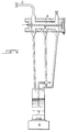
- Figure 3 is a representation of the equipment used for testing the barrier properties with virus suspensions.
- the upper reservoir is fitter with a valve on each outlet, a pressure gauge and a means to a generate pressure on the virus suspension.
- Inlet (4) is connected to a peristaltic pump 6 which draws the detector solution from a supply vessel (7) and outlets (5) feed the detector liquid back into 7.
- the liquid is stirred and heated by a magnetic stirrer/heater (8).
- the test is a diffusion technique where the barrier is clamped in place between two aqueous solutions.
- One solution contains bacteria and the other solution is sterile.
- the object of the procedure is to determine if the bacteria can contaminate the sterile solution by penetrating the barrier.
- Stress is established by raising the fluid level in the challenge half of the diffusion apparatus.
- the solution used should be in the surface tension range of blood and body fluids. Samples can be removed over time from the device without disturbing it or the test specimen. Different quality barriers can be distinguished by the options of increased time or pressure. All results are numerical by virtue of serial dilution plating.
- the apparatus consists of two chambers whose open faces fit together. Each chamber has a top inlet for introducing media or for exerting pressure on that chamber and each has a sample tap at the bottom.
- the barrier to be tested is placed between the open faces of the two chambers and the faces are clamped together.
- the challenge media containing the bacteria is introduced into one chamber of the sterilized diffusion device while simultaneously adding the detector media to the second to prevent a premature pressure gradient.
- the challenge media level is adjusted to give it a positive pressure vs . the detector media.
- Samples are withdrawn over time from the detector broth. At the end of the test the total contents of the detector chamber should be drained and mixed prior to plating. Overnight incubation of the detector media can be used for very low count samples.
- E. coli at a concentration of 2 x 10⁸ CFU/ml in tripticase soy broth was used as the challenging suspension. Exposure times were 30 minutes at 10.16 cm (4 inches) of water hydrostatic head on the challenge media.
- a coated product was made in accordance with the present invention using the apparatus shown in Figure 5.
- a roll coater was used in a 4-roll stack configuration in line with a take-up.
- the stack comprised of a gravure roll quadrangular pattern, 33 cells per centimeter, cell depth of 110 microns (33Q/110), pressure nipped to a polyurethane rubber roll, pressure nipped to a chrome roll, pressure nipped to a silicone rubber roll.
- the gravure roll was heated to 100°C and the chrome to 100°C; the polyurethane rubber roll in contact was also at an elevated temperature.
- the gravure roll was with a trough containing a reactive hot melt, hydrophilic polyurethane prepared from 4.4'-diphenylmethane diisocyanate, polyoxyethylene of number average molecular weight of 1450, and hydroquinone di(2-hydroxyethyl)ether prepared according to the teachings of U.S. Patent No. 4,532,316.
- the melt viscosity of said polyurethane was approximately 2000 cps as measured on a rheometer using parallel oscillating discs at the application temperature of 100°C.
- the hydrophilic polyurethane transferred from the gravure roll along the stack until it came in contact with the scaffold material.
- the scaffold material was expanded PTFE prepared according to the teachings of U. S. Patent No.
- Example 2 To illustrate the utility of this invention the coated product described in Example 1, is compared in Table 2 to structures currently sold into the protective garment industry.
- the product of the method of this invention provides equal to or superior protection to all of the alternative materials and furthermore does so simulatneously with an MVTR essentially equal to or greater than the alternatives.
- the resultant rate of moisture transfer by the product of the method of this invention is exceptionally high.
- the MVTR of the coated material is comparable to the uncoated substrate and in addition provides functional barrier properties not present in the substrate alone.
- substrates are selected with MVTR's of at least 5000 gm/m2/24 hrs. so that the substrate does not limit the high rate of moisture transfer.
Landscapes
- Engineering & Computer Science (AREA)
- Textile Engineering (AREA)
- Health & Medical Sciences (AREA)
- Chemical Kinetics & Catalysis (AREA)
- Chemical & Material Sciences (AREA)
- Animal Behavior & Ethology (AREA)
- Public Health (AREA)
- Heart & Thoracic Surgery (AREA)
- Vascular Medicine (AREA)
- Life Sciences & Earth Sciences (AREA)
- Dispersion Chemistry (AREA)
- General Health & Medical Sciences (AREA)
- Biomedical Technology (AREA)
- Veterinary Medicine (AREA)
- Laminated Bodies (AREA)
- Treatments For Attaching Organic Compounds To Fibrous Goods (AREA)
- Professional, Industrial, Or Sporting Protective Garments (AREA)
- Synthetic Leather, Interior Materials Or Flexible Sheet Materials (AREA)
- Socks And Pantyhose (AREA)
- Medicines Containing Material From Animals Or Micro-Organisms (AREA)
- Sampling And Sample Adjustment (AREA)
Abstract
Description
- This invention relates to a method for manufacturing which more particularly provide barrier protection against microorganisms, such as bacteria and viruses, and against airborne particulate matter.
- Surgical gowns, drapes and the like protect surgically prepared areas of the skin from contamination and also protect surgeons and nurses against contamination through contact with unprepared or contaminated areas of patient's skin. In addition, surgical gowns should present a sterile barrier to protect patients from contamination through contact with the surgeon, and vice versa.
- Liquid imperviousness of the gown or drape is recognized as an important property in assuring that the gown or drape presents a sterile surface and acts as a barrier to the passage of bacteria or virus. Body liquids and other liquids can permeate through the surgical gown or drape and contact the skin of the patient. Thus, bacteria and viruses, such as the AIDS virus, which are present on the surface of the gown or drape may be transported through the gown to the patient or the operating room personnel.
- In addition to being liquid repellent and a bacteria and viral barrier, hospital gowns desirably present a non-glare outer surface, are nonlinting, possess antistatic characteristics and, not least importantly, are comfortable to wear.
- It has been widely recognized that garments must be "breathable" to be comfortable. However, it is not necessary that air pass through the garment for it to be comfortable, only that water vapor from perspiration be trasmitted from inside to outside so that undergarments do not become wet and so that a natural evaporative cooling effect can be achieved. Breathability and ability to transport interior moisture vapor to the external environment are used interchangeably herein. If a continuous film of hydrophilic material is exposed to air containing substantial water vapor on one side of the film, and to air containing less water vapor on the other side, the side of the film exposed to the higher water vapor concentration will absorb water molecules which diffuse through the film and are desorbed or evaporated on the side exposed to the lower water vapor concentration. Thus, water vapor is effectively transported through the film on a molecule by molecule basis. This property is known as "breathability".
- One type of commonly used protective clothing is made from a polyolefin nonwoven substrate. While having reasonable properties for protection, garments constructed of this material are known to be very uncomfortable due to their inherent low moisture transmission characteristics, i.e their low breathability. Various attempts have been made to improve breathability of this nonwoven material. These efforts, however, result frequently in a more open structure of the nonwoven material and thus also simultaneously lower its protection value. Coatings on spun-bonded polyolefin have been employed to afford greater barrier protection to the 'open' base structure of the nonwoven. However, the already inherently low moisture transmission characteristics of the spun-bonded material are even further reduced, simultaneously reducing the comfort of garments made by use of this technology.
- Protective clothing in hospital operating rooms has been made of wood-pulp filled, spunlaced polyester, heavily treated with a water-repellent. Here again a compromise in properties must be reached. Greater comfort sacrifices maximum microorganism barrier protection and greater barrier protection lowers comfort. For instance, where hospital operating room gown products require superior protection from microorganisms over the base spun-laced polyester, a polyethylene film is usually laminated to the polyester. But, while achieving good barrier characteristics, moisture vapor transmission is substantially eliminated.
- Prior-filed EP-A-288,214 (date of filing 14.4.88, priority date 21.4.87, publication date 26.10.88) discloses a coated product comprising a substrate and a microporous scaffold having a void volume of greater than 40% of open interconnecting microstructure, the void being substantially filled with a chemical substance which may be a polymer.
- As seen from the foregoing, protection properties and comfort properties are traded off with one another. The present invention allows for both very desirable barrier protection characteristics while simultaneously achieving good moisture vapor transmitting characteristics; i.e. protection with comfort.
- A discovery has now been made towards a coating method in which the combination of a porous scaffold material, a hydrophilic polyurethane resin, and a substrate, all in proper relationship to one another, results in a coated product having desirable aesthetics and having useful microorganism and particulate barrier properties. Specifically, the coated product provides a functional barrier without compromising the comfort to the wearer. The functional barrier provided serves as an effective barrier to microorganisms and air-borne particulates.
- In this invention, a coating is applied to one side of a substrate in a particular manner to impart the desired barrier features. The coating is a combination of both a polymeric microporous scaffold layer and a hydrophilic polyurethane resin.
- Accordingly, the method of this invention comprises:
- a) forming a coating by contacting a microporous scaffold material having a microstructure of open interconnected voids wherein the void volume of the scaffold material is at least 65% of the total scaffold material volume, said scaffold material having a weight of between 1 and 10 g/m², with a hydrophilic polyurethane prepolymer between rolls, whereby the pressure between the rolls and the amount of polyurethane flow are adjusted to result in that the prepolymer forms a layer on the scaffold material and infiltrates partially into the pores of the microporous scaffold material without completely filling the same, the formed polyurethane layer having a weight of 5 - 25 g/m²
- b) contacting a substrate fabric having a moisture vapor transmission rate of at least 5000 g/m²/24 hrs with a layer of said coating between two rolls, while the prepolymer polymerizes, to attach the said coating only at specific elevated points on the substrate fabric.
- The surface of the coated fabric has a pleasing appearance which is due to the fact that the polyurethane resin does not fill the voids of the scaffold to the extent that the resin is present on the opposite side of the scaffold. Alternatively, to ensure that there is an exposed microporous face on the opposite side, a second layer of untreated scaffold can be applied to that surface.
- The products of the method of this invention, are continuous coatings and as such exhibit substantially no air permeability and so afford a barrier to air-borne, particulates. Furthermore, the products of this invention function as a barrier to microorganisms, such as viruses and bacteria. These barrier characteristics are achieved while the moisture vapor transmission rate (MVTR) of the coated product is only slightly lower than the MVTR of the uncoated starting substrate. Thus the product of this invention yields both protection and comfort maximizing both without compromising either. Notably, these features are also retained following gamma radiation sterilization.
- Figures 1 and 2 depict the construction of one embodiment of the invention.
- Figures 3 and 4 depict views of a machine used to test coated fabrics for viral barrier efficiency.
- Figure 5 is a schematic drawing of the process used in the invention.
- Figure 6 is a scanning electron microphotography of products of the invention.
- As used herein, a coated product or fabric is one in which a substrate is covered continuously on a surface with one or more materials to give the substrate a property it does not possess by itself.
- The substrate used in this invention can be any fabric that has a moisture vapor transmission rate of at least 5000 gm/m²/24 hr. The fabric may be woven, non-woven or knitted. The substrate may be made of paper. It may also have the form of a scrim, mesh, or grid. In applications such as hospital gowns, a textile fabric, such as a polyester-cotton blend, or a nonwoven material that contains wood pulp is often used as the substrate.
- The polymeric scaffold material is a microporus polymer having a microstructure of open, interconnecting voids and void volume of greater than 65%. It may preferably have a void volume greater than 70% or even 85%, for some applications. The scaffold material may have a thickness of less than 100 µm, preferably less than 35 µm, and most preferably less than 20 µm.
- Scaffold materials include films of microporous polyolefins, such as polytetrafluoroethylene, polypropylene, polyethylene and other microporous polymers, which possess high moisture vapor transmission rates.
- A preferred scaffold material is expanded polytetrafluoroethylene (PTFE). This material is characterized by a multiplicity of open, interconnecting voids, high strength, and stable chemical properties. U. S. Patent No. 3,953,566 and 4,187,390, describes the preparation of the desirable microporous, expanded, polytetrafluoroethylene films. These films are commercially available from W. L. Gore & Associates, Inc., and are sold under the trademark GORE-TEX.
- The hydrophilic polyurethane layer selectively transports water by diffusion but does not support pressure driven liquid flow. Therefore moisture is transported, but the continuous layer precludes passage of microorganisms and air.
- The polyurethanes useful herein comprise the product of a polyol of primarily oxyethylene units and a polyisocyanate. The polyol moiety comprises greater than 45% by weight of polyurethane, preferably greater than 60%, most preferably greater than 70%.
- One class of such polyurethanes are those that have a backbone of polyoxyethylene which end with toluene diisocyanate groups. It has a branched polyether with at least three reactive isocyanate groups.
- Another class of polyurethanes comprise the reaction product of:
- (i) a polyol (A) having a number average molecular weight of from about 600 to about 3500 and having a functionality of at least 2;
- (ii) an isocyanate (B) having a functionality of at least 2; and
- (iii) a low molecular weight chain extender (C) having a molecular weight in a range lower than about 500 and having a functionality of at least 2, wherein the reactants are employed in such proportions so as to satisfy the following equations:

- Preferred is the reaction product of:
- (i) a polyol (A) of primarily oxyethylene units, having a number average molecular weight of from about 600 to about 3500;
- (ii) a polyisocyanate (B); and
- (iii) a low molecular weight bifunctional chain extender (C) having a molecular weight in a range lower than about 500.
- Most preferred is the reaction product of:
- (i) a poly(alkylene ether)glycol (A) of primarily oxyethylene units, having a number average molecular weight of from about 600 to about 3500;
- (ii) a diisocyanate (B); and
- (iii) a low a molecular weight bifunctional chain extender (C) having a molecular weight in a range lower than about 500.
- These polyurethanes are described in greater detail in U. S. Patent No. 4,532,316.
- To prepare the products of the invention, the polyurethane in the form of its liquid phase is applied to one side of the scaffold material in a controlled amount so as to form a layer on the material and to partially infiltrate the voids of the material. The substrate is combined with the polyurethane side of the polyurethane/scaffold combination (coating) and subsequently caused to solidify and/or cure in a firm bond between the substrate and the coating.
- The coating method is illustrated in the following description of a four roll stack as illustrated in Figure 5. Metered control of polyurethane is provided for by a gravure roll, 1, and doctor blade/feed reservoir, 10. The polyurethane, 9, is applied in a controlled amount to the continuously moving, scaffold material, 5, in the nip between two rotating rolls, 2 and 3; one such rotating roll, 2, carrying a controlled amount of the polyurethane and the other such roll, 3, providing support so as to force the polyurethane partially into the porous structure of the scaffold material, 5. The coating, 7, (i.e. the scaffold material and polyurethane combination) is combined with the substrate, 6, in the nip between two rotating rolls, 3 and 4, resulting in the coated product, 8, of this invention. This method can be further modified to allow for a second substrate to be brought into the backside of the coating to cause a sandwich effect, the coating being between the two substrates.
- The pressure between
rolls - Refering to Figures 1 and 2, which depicts a representative coated product produced by the method of this invention,
substrate 1 is shown as a woven fabric made offibers 2 in Figure 1 and as a nonwoven fabric in Figure 2. Raised or elevated portions of the fabric are shown as 3. The polyurethane layer is shown as 4, and as seen, contacts and adheres to the substrate at raised orelevated points 3. Airspaces in the fabric are depicted as 8. The scaffold material is shown as 5 and the voids are shown as 6 and are partially filled with polyurethane as shown at 7. - The coating, the (combination of the polyurethane and scaffold material) is attached to the substrate in an unique way. The coating and the substrate attach only at elevated specific points. This is contrasted against what is normally seen in the prior art, where coatings in general seems to follow the contour of the substrate and/or fill in the voids and valleys in the substrate and as such is seen to not have an overall regular thickness. In otherwords, the coating herein on a microscopic scale is seen to span between the points of contact of the substrate rather than follow the contours of the surface.
- It is believed that it is this phenomenon that produces the good drape of the fabrics. Drape is defined as the way a fabric falls when hung in different positions. Drape is associated with flexibility and suppleness. Furthermore it is believed that it is the combination of scaffold & polyurethane that allows for such a thin hydrophilic polyurethane layer to be so continuous. It is this continuity that provides the desired functional barrier properties and the thinness that allows such high rates of water vapor transfer.
- While the products of the method of this invention find usefulness in hospital gowns because of their good viral and bacterial barrier properties, they also find use in other applications where such good microorganism barrier properties are desirable, such as hospital bedding, incontinent devices, hygienic products, and other like applications.
- The products of this invention also provide utility in applications where barrier control of airborne particulates are desired. For instance they find usefulness in asbestos clean-up where the worker needs to be comfortable, yet protected. Turning the protection concept around, the product also provides utility also in keeping body particulates away from sensitive material manufactured or used within a clean room.
- In the course of testing for bacterial and virus barriers for use in operating room garments, the work of Laufman, et al (Ann. Surg. 875, June 1975) was taken into account. They measured the stress forces on surgical barriers while in use and found forces in the order of 2.27 kg (5 lbs) at the elbow and 4.54 kg (10 lb.) at the waist. Assuming the elbow area encompasses a 10.16 cm (4 inch) diameter circle and the waist an area of 91.4 cm (36 inches), these forces equate to 28 kg/cm² (0.40 psi) and 19.7 kg/cm² (0.28 psi), respectively. To provide a degree of safety, virus barrier testing was peformed with pressure up to 1.3 bar (4 psig) across the membrane test specimen.
- A variety of different tests have bean used in the Examples. These are described as follows:
- Substrates and coated products of this invention were tested for Gurley seconds, defined as the time in seconds for 100 cc of air to flow through 6.45 cm² of test material under a pressure drop of 1.2 kPa. The Gurley seconds were converted to air permeability by dividing them into the 100 cc of air. As such the air permeability is reported in cc/min. of air through the test area. The test device, a Gurley Densometer Model 4110, or Model 4120, was employed in a method similar to Method A of ASTM D726-58. Model 4110 was used on uncoated substrates, 4120 on coated samples. Coated samples were oriented coating face up to ensure as an effective seal as possible, however care must be taken to minimize the leakage around the edge of the test area. As such an air permeability of less than 6 cc/min was used as the criteria herein to demonstrate no air flow.
- A description of the test employed to measure moisture vapor transmission rate (MVTR) is given below. The procedure has been found to be suitable for testing coatings and coated products.
- In the procedure, approximately 70 ml of a saturated salt solution of potassium acetate and distilled water was placed into a 133 ml polypropylene cup, having an inside diameter of 6.5 cm at the mouth. An expanded PTFE membrane, having a Gurley number of about 7 seconds, a bubble point of about 179 kPa determined as described in ASTM F316, thickness of about 37 microns and a weight of about 20 gms/m², available from W. L. Gore & Associates of Newark Delaware, was heat sealed to the lip of the cup to create a taut, leakproof, microporous barrier containing the salt solution. A similar expanded PTFE membrane was mounted taut within 12.5 cm embroidery hoop and floated upon the surface of a water bath. The water bath assembly was controlled at 23° C plus or minus 0.1°C, utilizing a temperature controlled room and a water circulating bath.
- Coated samples are then placed coated side down onto the surface of the floating expanded PTFE membrane.
- The cup assembly weighed to the nearest 1/1000 gm and was placed in an inverted manner onto the center of the test sample.
- Water transport was provided by the driving force between the water and the saturated salt solution providing water flux by diffusion in that direction. The sample was tested for 15 minutes and the cup assembly was then removed, weighed again to within 1/1000 gm.
- The MVTR of the sample was calculated from the weight gain of the cup assembly and was expressed in grams of water per square meter of sample surface area per 24 hours.
- A second cup assembly was simultaneously weighed to within 1/1000 gm and placed onto the test sample in an inverted manner as before. The test was repeated until a steady state MVTR was observed by two repetitive MVTR values. With thin coatings (less than 0.25 mm), this generally has been found to require only one test interval to achieve steady state information within the variability of the test.
- Coated products of the present invention were tested for coating continuity using a modified Suter test apparatus, which is a low water entry pressure challenge. Water was forced against a sample of 10 cm diameter sealed by two rubber gaskets in a clamped arrangement. The sample was mounted with the coating side down against the water. It is important that a leakproof seal is formed by the clamp mechanism, gaskets and sample. In deformable samples, the sample was held in place by a reinforcing scrim (e.g. open nonwoven). The sample was open to atmospheric conditions and was visible to the operator. The water pressure on the sample was increased to 6.89 kPa by a pump connected to a water reservoir, as indicated by an appropriate gauge and regulated by an in-line valve. The test sample was at an angle and the water was recirculating to assure water contact and not air against the sample's lower surface. The upper surface of the sample was visually observed for a period of at least 1 minute for the appearance of any water which would be forced through the sample. Liquid water seen on the surface was interpreted as a deficiency in the continuity of the coating. A passing grade was given for no liquid water visible within 3 minutes, thus indicating a continuous coating.
- A jig, as shown in Figures 3 and 4 was designed to hold the barrier being challenged.
- Above the barrier the virus suspension is contained in a pressurizable reservoir.
- Below the barrier a second reservoir contains a tryptone broth which is pumped so the bottom of the barrier is continuously washed by the broth. The washings are returned to a holding vessel for the broth. The upper reservoir is filled with a virus suspension (at least 1 x 10⁸ virus particles/ml) and is pressurized. Any virus particles passing through the barrier are washed into the broth. After a set period of time, the broth is sampled for assay.
- For testing virus barriers, a small icosahedral shaped bacteriophage (phi-X174) with a diameter of 27 nanometers was used. The suspending liquid was human serum. The test period was 30 minutes at 0.5 - 1 cm. of water pressure, 30 minutes at 4 cm water pressure, 30 minutes at 1.1 bar (1 psig.) and 30 minutes at (4 psi g.) 1.3 bar applied to the virus suspension reservoir. Broth samples were collected at the beginning and then at the end of each interval.
- For quantification, dilute the samples serially through 10 in tryptone broth. Add 0.5 ml. of each dilution into 2.5 ml of auto claved top agar in sterilized test tubes, add 1 drop of host bacteria suspension to each tube, mix well and pour over the surface of bottom agar plates. Incubate at 37± 2°C for 4 to 12 hours to get plaques large enough to count but not merging. Calculate the phage titer from the plaque count and report results in PFU/ml (plaque forming units/ml).
- In addition, any increase in volume of the circulating broth should be noted, indicating fluid flow from the top reservoir.
- Barrier efficiency is measured by observing the pressure at which virus breakthrough occurs up to 1.3 bar (4 psig). Any break through is judged a failure. Passing is no breakthrough at (4 psig.) 1.3 bar.
- The media used are shown below.
-
Tryptone broth: Bacto-tryptone 10.0 g KCl 5.0 g CaCl₂ 0.15 g purified water q.s. 1000 mL adjust to pH 7.3 with 2.5 N NaOH; sterilize Top agar: Bacto-agar 6.5 g tryptone 13.0 g NaCl 8.0 g Glucose 3.0 g sodium citrate 2.0 g purified water q.s. 1000 mL Add each ingredient in order. Adjust to pH 7.5 with 2.5 N NaOH or HCl autoclave. Bottom agar: Bacto-agar 10.0 g tryptone 13.0 g NaCl 8.0 g Glucose 1.3 g sodium citrate 2.0 g purified water q.s. 1000 mL Add each ingredient in order. Adjust to pH 7.5 with 2.5 N NaOH or HCl autoclave, pour into plates. - Figure 2 is a drawing of the jig used in the virus barrier effeciency test. 1 is the barrier under test, 2 is the reservoir holding the virus suspension, 3 is the reservoir containing the detector solution, 4 is the inlet and 5 the outlets for circulating the detector solution.
- Figure 3 is a representation of the equipment used for testing the barrier properties with virus suspensions. The upper reservoir is fitter with a valve on each outlet, a pressure gauge and a means to a generate pressure on the virus suspension. Inlet (4) is connected to a
peristaltic pump 6 which draws the detector solution from a supply vessel (7) and outlets (5) feed the detector liquid back into 7. The liquid is stirred and heated by a magnetic stirrer/heater (8). - In considering the concepts of stress, surface tension, and liquid penetration, a test method was devised.
- The test is a diffusion technique where the barrier is clamped in place between two aqueous solutions. One solution contains bacteria and the other solution is sterile. The object of the procedure is to determine if the bacteria can contaminate the sterile solution by penetrating the barrier.
- Stress is established by raising the fluid level in the challenge half of the diffusion apparatus. The solution used should be in the surface tension range of blood and body fluids. Samples can be removed over time from the device without disturbing it or the test specimen. Different quality barriers can be distinguished by the options of increased time or pressure. All results are numerical by virtue of serial dilution plating.
- The apparatus consists of two chambers whose open faces fit together. Each chamber has a top inlet for introducing media or for exerting pressure on that chamber and each has a sample tap at the bottom. The barrier to be tested is placed between the open faces of the two chambers and the faces are clamped together. The challenge media containing the bacteria is introduced into one chamber of the sterilized diffusion device while simultaneously adding the detector media to the second to prevent a premature pressure gradient.
- The challenge media level is adjusted to give it a positive pressure vs. the detector media.
- Samples are withdrawn over time from the detector broth. At the end of the test the total contents of the detector chamber should be drained and mixed prior to plating. Overnight incubation of the detector media can be used for very low count samples.
- Samples are plated on agar with dilutions of 1, 100, 10,000 and 1,000,000. Results are recorded in CFU/ml (colony forming units/ml).
- For these test, E. coli at a concentration of 2 x 10⁸ CFU/ml in tripticase soy broth was used as the challenging suspension. Exposure times were 30 minutes at 10.16 cm (4 inches) of water hydrostatic head on the challenge media.
- A coated product was made in accordance with the present invention using the apparatus shown in Figure 5. A roll coater was used in a 4-roll stack configuration in line with a take-up. The stack comprised of a gravure roll quadrangular pattern, 33 cells per centimeter, cell depth of 110 microns (33Q/110), pressure nipped to a polyurethane rubber roll, pressure nipped to a chrome roll, pressure nipped to a silicone rubber roll. The gravure roll was heated to 100°C and the chrome to 100°C; the polyurethane rubber roll in contact was also at an elevated temperature. The gravure roll was with a trough containing a reactive hot melt, hydrophilic polyurethane prepared from 4.4'-diphenylmethane diisocyanate, polyoxyethylene of number average molecular weight of 1450, and hydroquinone di(2-hydroxyethyl)ether prepared according to the teachings of U.S. Patent No. 4,532,316. The melt viscosity of said polyurethane was approximately 2000 cps as measured on a rheometer using parallel oscillating discs at the application temperature of 100°C. The hydrophilic polyurethane transferred from the gravure roll along the stack until it came in contact with the scaffold material. The scaffold material was expanded PTFE prepared according to the teachings of U. S. Patent No. 3,953,566 and 4,187,390, having a weight of about 2-3 gm/m² and having a void volume greater than 65%. The coating (i.e. combination of scaffold and polyurethane) was brought into contact with a 70 gm/m² pulp filled polyester spunlaced nonwoven at the chrome roll/silicone roll nip. The coated product thus made was then collected on the take-up. The coated product was then cured under ambient conditions for 48 hours. The product was aesthetically pleasing having good drape. A representative photomicrograph is seen in Figure 6 at 200x. A commercially available O.R. gown; American Converter's OPTIMA® fabric, is representative of pulp filled polyester supnlaced nonwoven to be compared against the coated product of this invention. The final properties of the coated product are listed in Table 1 along with the OPTIMA® substrate. All properties were characterized by the appropriate tests described above. The virus barrier efficiency test was carried out after 2.5 to 5 megarad gamma radiation sterilization.
- As can be seen from the data, a high moisture transmitting product exhibiting the barrier properties claimed herein was demonstrated.
-
Table 1 Optima Substrate Coated Product Coating Weight (gm/m²) N/A 11.8 MVTR (gms/m²/24 hrs.) 26,700 22,400 Suter Continuity Test (1 psig/3min) (1.08 bar/3min) Fail Pass Air Permeability (cc/min.) 6000 6 Virus Barrier Efficiency Test (psig) Fail (0.5-1 psig) (1.05-1.08 bar) Pass ( 4 psig) (1.3 bar) - To illustrate the utility of this invention the coated product described in Example 1, is compared in Table 2 to structures currently sold into the protective garment industry.
- The following are representive of the materials being sold for disposable applications.
-
Sample 1 = - spunbonded polyolefin
-
Sample 2 = - two layers, spunbonded polypropylene
-
Sample 3 = - spunlaced wood pulp polyester
-
Sample 4 = - spunlaced wood pulp polyester with polyethylene film reinforcement.
- In addition,
Sample 5 is a high count (280), 50/50 polyester/cotton blend, fluid repellent treated, which is representative of a reuseable product was tested. All materials were tested as received.Table 2 Sample 1Sample 2Sample 3Sample 4Sample 5Coated Product of Example 1 Weight (gm/m²) 47 112 76 123 217 85 MVTR (gm/m²/24hr.) 5,000 7,400 26,700 400 16,500 22,400 Suter Continuity Fail Fail Fail Pass Fail Pass Air Permeability (cc/min.) 6,000 6,000 6,000 6 2,140 6 Viral Barrier Efficiency Test NT NT Fail (0.5 psig) (1.05 bar) Pass (4 psig) (1.3 bar) Fail (0 psig) (1 bar) Pass (4 psig) (1.3 bar) NT = not tested as sample failed Suter continuity test. - As can be clearly seen, the product of the method of this invention provides equal to or superior protection to all of the alternative materials and furthermore does so simulatneously with an MVTR essentially equal to or greater than the alternatives.
- To illustrate the flexiblility of this product to substrate selection, various base substrates were produced as in Example 1. Substrates illustrated:
-
Sample 1 = - 67 gm/m² spunlaced 100% polyester
-
Sample 2 = - 40 gm/m² spunlaced 100% polyester
-
Sample 3 = - 67 gm/m² point bonded nylon
-
Sample 4 = - 42 gm/m² tricot knit
- The resultant rate of moisture transfer by the product of the method of this invention is exceptionally high. In many cases, the MVTR of the coated material is comparable to the uncoated substrate and in addition provides functional barrier properties not present in the substrate alone. To take advantage of this feature of the invention, substrates are selected with MVTR's of at least 5000 gm/m²/24 hrs. so that the substrate does not limit the high rate of moisture transfer.
- To illustrate a most preferred range of scaffold weight, three products of the method of this invention were made as in Example 1 with the only difference being the scaffold weight employed.
Table 4 Coated Product Coated Product Coated Product A B C Scaffold Weight (gm/m²) 9.6 6.1 2.8 MVTR (gm/m².24hrs.) 19,000 21,000 22,400 Suter Continuity Test Pass Pass Pass Air Permeability (cc/min) 6 6 6
| | | | | |||||
| Control* | Coated | Control* | Coated | Control* | Coated | Control* | Coated | |
| MVTR (gm/m²/24hr.) | 25,500 | 26,200 | 31,300 | 27,700 | 27,800 | 19,600 | 46,336 | 22,300 |
| Suter Continuity Test | Fail | Pass | Fail | Pass | Fail | Pass | Fail | Pass |
| Air Permeability Test (cc/min) | 6,000 | 6 | 6000 | 6 | 6000 | 6 | 6,000 | 6 |
| *The controls are the uncoated equivalent or a representative of same. |
Claims (1)
- A method for making a coated product comprisinga) forming a coating by contacting a microporous scaffold material having a microstructure of open interconnected voids wherein the void volume of the scaffold material is at least 65% of the total scaffold material volume, said scaffold material having a weight of between 1 and 10 g/m², with a hydrophilic polyurethane prepolymer between rolls, whereby the pressure between the rolls and the amount of polyurethane flow are adjusted to result in that the prepolymer forms a layer on the scaffold material and infiltrates partially into the pores of the microporous scaffold material without completely filling the same, the formed polyurethane layer having a weight of 5 - 25 g/m²b) contacting a substrate fabric having a moisture vapor transmission rate of at least 5000 g/m²/24 hrs with a layer of said coating between two rolls, while the prepolymer polymerizes, to attach the said coating only at specific elevated points on the substrate fabric.
Applications Claiming Priority (3)
| Application Number | Priority Date | Filing Date | Title |
|---|---|---|---|
| US07/215,669 US4961985A (en) | 1988-07-06 | 1988-07-06 | Fabrics for protective clothing |
| US215669 | 1988-07-06 | ||
| CA 605027 CA1333680C (en) | 1988-07-06 | 1989-07-07 | Fabrics for protective clothing, processes for making them and test methods |
Publications (2)
| Publication Number | Publication Date |
|---|---|
| EP0374245A1 EP0374245A1 (en) | 1990-06-27 |
| EP0374245B1 true EP0374245B1 (en) | 1994-01-19 |
Family
ID=25672864
Family Applications (1)
| Application Number | Title | Priority Date | Filing Date |
|---|---|---|---|
| EP19890908082 Expired - Lifetime EP0374245B1 (en) | 1988-07-06 | 1989-07-06 | Fabrics for protective clothing, processes for making them |
Country Status (9)
| Country | Link |
|---|---|
| US (1) | US4961985A (en) |
| EP (1) | EP0374245B1 (en) |
| JP (1) | JPH0667604B2 (en) |
| AT (1) | ATE100508T1 (en) |
| AU (1) | AU618112B2 (en) |
| CA (1) | CA1333680C (en) |
| DE (1) | DE68912545T2 (en) |
| NO (1) | NO901029L (en) |
| WO (1) | WO1990000643A2 (en) |
Families Citing this family (43)
| Publication number | Priority date | Publication date | Assignee | Title |
|---|---|---|---|---|
| US5134017A (en) * | 1988-09-02 | 1992-07-28 | Precision Fabrics Group, Inc. | Foam coated protective apparel fabric |
| JPH088879B2 (en) * | 1989-09-13 | 1996-01-31 | 田辺製薬株式会社 | Process for producing optically active 3-phenylglycidate compounds |
| US5268212A (en) * | 1989-10-17 | 1993-12-07 | Malden Mills Industries, Inc. | Windproof and water resistant composite fabric with barrier layer |
| US5204156A (en) * | 1989-10-17 | 1993-04-20 | Malden Mills Industries, Inc. | Windproof and water resistant composite fabric with barrier layer |
| US4963416A (en) * | 1989-11-13 | 1990-10-16 | W. L. Gore & Associates, Inc. | Method to reduce the damage caused by ionizing radiation to polyurethane/porous expanded polytetrafluroethylene composites by use of hindered phenols |
| US5036551A (en) * | 1990-02-16 | 1991-08-06 | W. L. Gore & Associates, Inc. | Elastomeric composite fabric |
| US5007123A (en) * | 1990-07-05 | 1991-04-16 | Comfortex, Inc. | Flexible covering for reducing moisture/vapor/bacteria transmission |
| GB9020917D0 (en) * | 1990-09-26 | 1990-11-07 | Lantor U K Limited | Improvements in or relating to barrier fabrics and garments made from barrier fabrics |
| US5160773A (en) * | 1991-08-16 | 1992-11-03 | W. L. Gore & Associates, Inc. | Encapsulated felt |
| US5935370A (en) * | 1991-10-18 | 1999-08-10 | #M Innovative Properties Company Minnesota Mining And Manufacturing Co. | Method for laminating a viral barrier microporous membrane to a nonwoven web to prevent transmission of viral pathogens |
| US5690949A (en) * | 1991-10-18 | 1997-11-25 | Minnesota Mining And Manufacturing Company | Microporous membrane material for preventing transmission of viral pathogens |
| US5260360A (en) * | 1991-10-18 | 1993-11-09 | Minnesota Mining And Manufacturing Company | Oil, water and sweat repellent microporous membrane materials |
| US5335372A (en) * | 1992-03-12 | 1994-08-09 | Rotecno Ag | Article of clothing, in particular for the medical or chemical field |
| US5239037A (en) * | 1992-07-16 | 1993-08-24 | Surface Coatings, Inc. | Waterproof breathable polyurethane membranes and porous substrates protected therewith |
| US5208313A (en) * | 1992-07-16 | 1993-05-04 | Surface Coatings, Inc. | Waterproof breathable polyurethane membranes and porous substrates protected therewith |
| US5238732A (en) * | 1992-07-16 | 1993-08-24 | Surface Coatings, Inc. | Waterproof breathable polyurethane membranes and porous substrates protected therewith |
| US5234525A (en) * | 1992-07-16 | 1993-08-10 | Surface Coatings, Inc. | Waterproof breathable fabric laminates and method for producing same |
| US6406674B1 (en) | 1993-06-30 | 2002-06-18 | Kimberly-Clark Worldwide, Inc. | Single step sterilization wrap system |
| CA2111071E (en) * | 1993-06-30 | 2011-08-23 | Sonya Nicholson Bourne | Single step sterilization wrap system |
| CA2116081C (en) | 1993-12-17 | 2005-07-26 | Ann Louise Mccormack | Breathable, cloth-like film/nonwoven composite |
| US6117800A (en) * | 1994-04-21 | 2000-09-12 | Encompass Group, L.L.C. | Surgical gown material |
| CN1149327A (en) * | 1994-05-06 | 1997-05-07 | W·L·戈尔及同仁股份有限公司 | Three-dimensional seamless waterproof breathable flexible composite articles |
| US5786058A (en) * | 1995-04-03 | 1998-07-28 | Minnesota Mining & Mfg | Thermally bonded viral barrier composite |
| US6114024A (en) * | 1995-08-01 | 2000-09-05 | Kimberly-Clark Worldwide, Inc. | Multilayer breathable film |
| US6420622B1 (en) * | 1997-08-01 | 2002-07-16 | 3M Innovative Properties Company | Medical article having fluid control film |
| US7560399B2 (en) * | 1998-08-28 | 2009-07-14 | Mmi-Ipco, Llc | Multi-layer composite fabric garment |
| WO2000013889A1 (en) | 1998-09-08 | 2000-03-16 | Brookwood Companies Incorporated | Breathable waterproof laminate and method for making same |
| US20060084336A1 (en) * | 1999-08-10 | 2006-04-20 | Warwick Mills, Inc. | High strength lightweight composite fabric with low gas permeability |
| US6638605B1 (en) | 1999-11-16 | 2003-10-28 | Allegiance Corporation | Intermittently bonded nonwoven disposable surgical laminates |
| JP4015434B2 (en) * | 2002-02-14 | 2007-11-28 | ジャパンゴアテックス株式会社 | Laminated fabric |
| US20030194547A1 (en) * | 2002-04-15 | 2003-10-16 | Fuhrmann Louis P. | Membrane composite structure and method of production |
| US20040121678A1 (en) * | 2002-12-19 | 2004-06-24 | Baldwin A. Frank | Liquid impervious and pathogen impervious laminate having antistatic properties |
| US20050197480A1 (en) * | 2004-03-05 | 2005-09-08 | Temple Rodger G. | Barrier coating comprising a polyurethane dispersion and elastomeric material |
| US20050196603A1 (en) * | 2004-03-08 | 2005-09-08 | Carr Mark E. | Anti-microbial breathable laminate |
| US7922983B2 (en) | 2005-07-28 | 2011-04-12 | Kimberly-Clark Worldwide, Inc. | Sterilization wrap with additional strength sheet |
| US20100077529A1 (en) * | 2005-09-30 | 2010-04-01 | General Electric Company | Article, laminate and associated methods |
| US20090205116A1 (en) * | 2005-09-30 | 2009-08-20 | General Electric Company | Article, laminate and associated methods |
| US8048516B2 (en) * | 2008-11-21 | 2011-11-01 | Bha Group, Inc. | Air permeable waterproof bicomponent film |
| GB2467554A (en) * | 2009-02-04 | 2010-08-11 | Systagenix Wound Man Ip Co Bv | A wound dressing material featuring polyurethane foam integrated into a solid substrate |
| US9102563B2 (en) * | 2009-10-15 | 2015-08-11 | Greg S. Laughlin | Environmentally rugged free-space fiber waveguide connector and method of manufacture thereof |
| KR101313896B1 (en) * | 2013-04-12 | 2013-10-01 | 김태훈 | Porous lamination film and manufacturing method thereof |
| WO2020028331A1 (en) * | 2018-07-31 | 2020-02-06 | W.L. Gore & Associates, Inc. | Polyethylene film |
| CA3105755C (en) * | 2018-07-31 | 2023-08-01 | Brent Bell | Polyethylene film |
Family Cites Families (26)
| Publication number | Priority date | Publication date | Assignee | Title |
|---|---|---|---|---|
| US3594263A (en) * | 1967-03-27 | 1971-07-20 | Millipore Corp | Laminated sheet for electrophoresis |
| GB1218042A (en) * | 1968-01-30 | 1971-01-06 | St Annes Board Mill Co Ltd | Laminate |
| US3553067A (en) * | 1968-03-25 | 1971-01-05 | Millipore Corp | Laminated sheet for evaluating diffusive reactions |
| CA936341A (en) * | 1970-01-28 | 1973-11-06 | Parke, Davis And Company | Medical-surgical dressing for burns and the like |
| CA962021A (en) * | 1970-05-21 | 1975-02-04 | Robert W. Gore | Porous products and process therefor |
| US3679540A (en) * | 1970-11-27 | 1972-07-25 | Celanese Corp | Reinforced microporous film |
| US4194041A (en) * | 1978-06-29 | 1980-03-18 | W. L. Gore & Associates, Inc. | Waterproof laminate |
| US4344999A (en) * | 1980-04-22 | 1982-08-17 | W. L. Gore & Associates, Inc. | Breathable laminate |
| US4433026A (en) * | 1981-10-29 | 1984-02-21 | Standard Textile Company, Inc. | Cloth-like material for forming a surgical gown and/or a surgical drape and method of making the same |
| JPS5915574A (en) * | 1982-07-15 | 1984-01-26 | ソニー株式会社 | Garment material |
| JPS5953786A (en) * | 1982-09-17 | 1984-03-28 | カネボウ株式会社 | Moisture permeable waterproof cloth |
| US4443511A (en) * | 1982-11-19 | 1984-04-17 | W. L. Gore & Associates, Inc. | Elastomeric waterproof laminate |
| EG16208A (en) * | 1982-11-19 | 1987-10-30 | Gore & Ass | Polytetrafluoroethylene laminate for footwear articles |
| AU2244683A (en) * | 1983-05-03 | 1984-11-08 | W.L. Gore & Associates, Inc. | Breathable static electrically conductive laminate |
| US4636424A (en) * | 1984-01-23 | 1987-01-13 | Unitika Ltd. | Moisture-permeable waterproof laminated fabric and process for producing the same |
| US4561435A (en) * | 1984-04-04 | 1985-12-31 | Chesebrough-Ponds, Inc. | Wound dressing |
| US4532316A (en) * | 1984-05-29 | 1985-07-30 | W. L. Gore & Assoc., Inc. | Phase separating polyurethane prepolymers and elastomers prepared by reacting a polyol having a molecular weight of 600-3500 and isocyanate and a low molecular weight chain extender in which the ratios of reactants have a limited range |
| US4613544A (en) * | 1984-12-04 | 1986-09-23 | Minnesota Mining And Manufacturing Co. | Waterproof, moisture-vapor permeable sheet material and method of making the same |
| JPH0627216B2 (en) * | 1984-12-11 | 1994-04-13 | ジャパンゴアテックス株式会社 | Stretchable moisture-permeable waterproof film for clothing |
| JPS625521A (en) * | 1985-07-01 | 1987-01-12 | 株式会社 潤工社 | Electrically insulating material |
| GB8620484D0 (en) * | 1986-08-22 | 1986-10-01 | Raychem Ltd | Plugged microporous film |
| US4789526A (en) * | 1986-12-15 | 1988-12-06 | Pall Corporation | Vacuum diagnostic device |
| AU619175B2 (en) * | 1987-04-21 | 1992-01-23 | W.L. Gore & Associates, Inc. | Coated products and methods for making |
| DE3872920T2 (en) * | 1987-04-21 | 1996-02-08 | Gore & Ass | Coated products. |
| AU1328588A (en) * | 1987-04-21 | 1988-10-27 | W.L. Gore & Associates, Inc. | Coated articles and methods for making |
| US4833026A (en) * | 1987-10-08 | 1989-05-23 | Minnesota Mining And Manufacturing Company | Breathable, waterproof sheet materials and methods for making the same |
-
1988
- 1988-07-06 US US07/215,669 patent/US4961985A/en not_active Expired - Lifetime
-
1989
- 1989-07-06 WO PCT/US1989/002932 patent/WO1990000643A2/en not_active Ceased
- 1989-07-06 EP EP19890908082 patent/EP0374245B1/en not_active Expired - Lifetime
- 1989-07-06 DE DE89908082T patent/DE68912545T2/en not_active Expired - Lifetime
- 1989-07-06 AT AT89908082T patent/ATE100508T1/en not_active IP Right Cessation
- 1989-07-06 JP JP50757589A patent/JPH0667604B2/en not_active Expired - Lifetime
- 1989-07-06 AU AU38729/89A patent/AU618112B2/en not_active Expired
- 1989-07-07 CA CA 605027 patent/CA1333680C/en not_active Expired - Lifetime
-
1990
- 1990-03-05 NO NO90901029A patent/NO901029L/en unknown
Also Published As
| Publication number | Publication date |
|---|---|
| WO1990000643A3 (en) | 1990-06-14 |
| DE68912545T2 (en) | 1994-05-05 |
| JPH0667604B2 (en) | 1994-08-31 |
| US4961985A (en) | 1990-10-09 |
| NO901029D0 (en) | 1990-03-05 |
| JPH02503335A (en) | 1990-10-11 |
| EP0374245A1 (en) | 1990-06-27 |
| AU3872989A (en) | 1990-02-05 |
| ATE100508T1 (en) | 1994-02-15 |
| AU618112B2 (en) | 1991-12-12 |
| NO901029L (en) | 1990-03-05 |
| CA1333680C (en) | 1994-12-27 |
| DE68912545D1 (en) | 1994-03-03 |
| WO1990000643A2 (en) | 1990-01-25 |
Similar Documents
| Publication | Publication Date | Title |
|---|---|---|
| US4961985A (en) | Fabrics for protective clothing | |
| EP0039184B1 (en) | A flexible layered article | |
| US5560974A (en) | Breathable non-woven composite barrier fabric and fabrication process | |
| US5445874A (en) | Waterproof, blood-proof and virus-proof breathable laminates | |
| US5409761A (en) | Breathable non-woven composite barrier fabric and fabrication process | |
| EP1109666B1 (en) | Breathable waterproof laminate and method for making same | |
| DE69100509T2 (en) | TISSUE STRUCTURE FROM ELASTOMERS. | |
| US5728451A (en) | Breathable non-woven composite viral penetration barrier fabric and fabrication process | |
| EP0455645B1 (en) | Microporous hydrophobic fluoropolymer composites | |
| EP0948431B1 (en) | Improved cloth-like, liquid-impervious, breathable composite barrier fabric | |
| KR100701711B1 (en) | Articles comprising impregnated thermoplastic members and methods of making the articles | |
| AU736963B2 (en) | Breathable elastic film/nonwoven laminate | |
| EP1015513B1 (en) | Stable breathable elastic articles | |
| US20010027303A1 (en) | Absorbent articles having reduced topsheet adhesion | |
| US5308689A (en) | Snag-resistant composite fabric | |
| US20030215617A1 (en) | Waterproof and breathable microporous thermoplastic laminated fabric | |
| US5599610A (en) | Trilaminate fabric for surgical gowns and drapes | |
| US5698307A (en) | Quadlaminate fabric for surgical gowns and drapes | |
| CN112140650A (en) | Medical protective clothing composite non-woven fabric material capable of being washed repeatedly and preparation method thereof | |
| MXPA01009866A (en) | Absorbent article with breathable backsheet comprising one layer with improved capillary apertures. | |
| CA2068491C (en) | Breathable composite barrier fabric | |
| AU743673B2 (en) | Improved cloth-like, liquid-impervious, breathable composite barrier fabric | |
| CA2247577A1 (en) | Reusable absorbent surgical drape | |
| HK1038536B (en) | Breathable waterproof laminate and method for making same |
Legal Events
| Date | Code | Title | Description |
|---|---|---|---|
| PUAI | Public reference made under article 153(3) epc to a published international application that has entered the european phase |
Free format text: ORIGINAL CODE: 0009012 |
|
| 17P | Request for examination filed |
Effective date: 19900126 |
|
| AK | Designated contracting states |
Kind code of ref document: A1 Designated state(s): AT BE CH DE FR GB IT LI LU NL SE |
|
| D17D | Deferred search report published (deleted) | ||
| 17Q | First examination report despatched |
Effective date: 19920402 |
|
| GRAA | (expected) grant |
Free format text: ORIGINAL CODE: 0009210 |
|
| AK | Designated contracting states |
Kind code of ref document: B1 Designated state(s): AT BE CH DE FR GB IT LI LU NL SE |
|
| PG25 | Lapsed in a contracting state [announced via postgrant information from national office to epo] |
Ref country code: AT Effective date: 19940119 Ref country code: LI Effective date: 19940119 Ref country code: CH Effective date: 19940119 Ref country code: BE Effective date: 19940119 Ref country code: NL Effective date: 19940119 |
|
| REF | Corresponds to: |
Ref document number: 100508 Country of ref document: AT Date of ref document: 19940215 Kind code of ref document: T |
|
| REF | Corresponds to: |
Ref document number: 68912545 Country of ref document: DE Date of ref document: 19940303 |
|
| ITF | It: translation for a ep patent filed | ||
| ET | Fr: translation filed | ||
| REG | Reference to a national code |
Ref country code: CH Ref legal event code: PL |
|
| NLV1 | Nl: lapsed or annulled due to failure to fulfill the requirements of art. 29p and 29m of the patents act | ||
| PG25 | Lapsed in a contracting state [announced via postgrant information from national office to epo] |
Ref country code: LU Free format text: LAPSE BECAUSE OF NON-PAYMENT OF DUE FEES Effective date: 19940731 |
|
| PLBE | No opposition filed within time limit |
Free format text: ORIGINAL CODE: 0009261 |
|
| STAA | Information on the status of an ep patent application or granted ep patent |
Free format text: STATUS: NO OPPOSITION FILED WITHIN TIME LIMIT |
|
| 26N | No opposition filed | ||
| EAL | Se: european patent in force in sweden |
Ref document number: 89908082.4 |
|
| REG | Reference to a national code |
Ref country code: GB Ref legal event code: IF02 |
|
| PGFP | Annual fee paid to national office [announced via postgrant information from national office to epo] |
Ref country code: DE Payment date: 20080829 Year of fee payment: 20 |
|
| PGFP | Annual fee paid to national office [announced via postgrant information from national office to epo] |
Ref country code: IT Payment date: 20080728 Year of fee payment: 20 Ref country code: FR Payment date: 20080729 Year of fee payment: 20 |
|
| PGFP | Annual fee paid to national office [announced via postgrant information from national office to epo] |
Ref country code: GB Payment date: 20080729 Year of fee payment: 20 |
|
| PGFP | Annual fee paid to national office [announced via postgrant information from national office to epo] |
Ref country code: SE Payment date: 20080729 Year of fee payment: 20 |
|
| REG | Reference to a national code |
Ref country code: GB Ref legal event code: PE20 Expiry date: 20090705 |
|
| EUG | Se: european patent has lapsed | ||
| PG25 | Lapsed in a contracting state [announced via postgrant information from national office to epo] |
Ref country code: GB Free format text: LAPSE BECAUSE OF EXPIRATION OF PROTECTION Effective date: 20090705 |