EP0373511B1 - Indirectly heated cathode assembly. - Google Patents
Indirectly heated cathode assembly. Download PDFInfo
- Publication number
- EP0373511B1 EP0373511B1 EP89122590A EP89122590A EP0373511B1 EP 0373511 B1 EP0373511 B1 EP 0373511B1 EP 89122590 A EP89122590 A EP 89122590A EP 89122590 A EP89122590 A EP 89122590A EP 0373511 B1 EP0373511 B1 EP 0373511B1
- Authority
- EP
- European Patent Office
- Prior art keywords
- cathode
- sleeve
- straps
- cathode sleeve
- heat reflecting
- Prior art date
- Legal status (The legal status is an assumption and is not a legal conclusion. Google has not performed a legal analysis and makes no representation as to the accuracy of the status listed.)
- Expired - Lifetime
Links
- 239000000463 material Substances 0.000 description 8
- 238000009413 insulation Methods 0.000 description 7
- 229910052715 tantalum Inorganic materials 0.000 description 5
- GUVRBAGPIYLISA-UHFFFAOYSA-N tantalum atom Chemical compound [Ta] GUVRBAGPIYLISA-UHFFFAOYSA-N 0.000 description 5
- 229910001080 W alloy Inorganic materials 0.000 description 4
- 229910045601 alloy Inorganic materials 0.000 description 4
- 239000000956 alloy Substances 0.000 description 4
- 229910001029 Hf alloy Inorganic materials 0.000 description 3
- 230000015556 catabolic process Effects 0.000 description 2
- 230000002950 deficient Effects 0.000 description 2
- 238000006731 degradation reaction Methods 0.000 description 2
- 230000002093 peripheral effect Effects 0.000 description 2
- 229910052721 tungsten Inorganic materials 0.000 description 2
- 239000010937 tungsten Substances 0.000 description 2
- OAICVXFJPJFONN-UHFFFAOYSA-N Phosphorus Chemical compound [P] OAICVXFJPJFONN-UHFFFAOYSA-N 0.000 description 1
- 230000032683 aging Effects 0.000 description 1
- 230000000712 assembly Effects 0.000 description 1
- 238000000429 assembly Methods 0.000 description 1
- 238000009125 cardiac resynchronization therapy Methods 0.000 description 1
- 239000011521 glass Substances 0.000 description 1
- 229910052741 iridium Inorganic materials 0.000 description 1
- GKOZUEZYRPOHIO-UHFFFAOYSA-N iridium atom Chemical compound [Ir] GKOZUEZYRPOHIO-UHFFFAOYSA-N 0.000 description 1
- 238000004519 manufacturing process Methods 0.000 description 1
- 238000005259 measurement Methods 0.000 description 1
- 239000000203 mixture Substances 0.000 description 1
- 230000002035 prolonged effect Effects 0.000 description 1
- 230000005855 radiation Effects 0.000 description 1
- 239000000126 substance Substances 0.000 description 1
- 239000000758 substrate Substances 0.000 description 1
- WFKWXMTUELFFGS-UHFFFAOYSA-N tungsten Chemical compound [W] WFKWXMTUELFFGS-UHFFFAOYSA-N 0.000 description 1
- 238000007740 vapor deposition Methods 0.000 description 1
- 239000012808 vapor phase Substances 0.000 description 1
- 238000001947 vapour-phase growth Methods 0.000 description 1
Images


Classifications
-
- H—ELECTRICITY
- H01—ELECTRIC ELEMENTS
- H01J—ELECTRIC DISCHARGE TUBES OR DISCHARGE LAMPS
- H01J29/00—Details of cathode-ray tubes or of electron-beam tubes of the types covered by group H01J31/00
- H01J29/02—Electrodes; Screens; Mounting, supporting, spacing or insulating thereof
- H01J29/04—Cathodes
-
- H—ELECTRICITY
- H01—ELECTRIC ELEMENTS
- H01J—ELECTRIC DISCHARGE TUBES OR DISCHARGE LAMPS
- H01J1/00—Details of electrodes, of magnetic control means, of screens, or of the mounting or spacing thereof, common to two or more basic types of discharge tubes or lamps
- H01J1/02—Main electrodes
- H01J1/13—Solid thermionic cathodes
- H01J1/20—Cathodes heated indirectly by an electric current; Cathodes heated by electron or ion bombardment
Definitions
- the strap 12 for supporting the cathode sleeve 7 is located such that it is not in contact with the heat reflecting cylinder 13. That is, the strap 12 extends below the heat reflecting cylinder 13 with a major portion parallel to the axis of the cylinder 13, and is welded to the upper end of the holder 11.
- the cathode disc 10 is hidden, by the heat reflecting cylinder 13, from view at at least that portion (a portion indicated by B in Fig. 2) of the insulation support which is defined between the embedded spot of the first grid 15 and that of the securing piece 17.
- the dissipation power has only to be about one-third that of the conventional assembly shown in Fig. 1, noting that the invention is 0.7 W and the conventional assembly is 2 W. Therefore, the indirectly heated cathode assembly of the present invention can be mounted on an oxide cathode-incorporated CRT without the need of altering an associated circuit.
- the cutoff voltage of the red, green and blue electron guns is so controlled as to develop predetermined color.
Landscapes
- Electrodes For Cathode-Ray Tubes (AREA)
- Solid Thermionic Cathode (AREA)
- Electron Sources, Ion Sources (AREA)
Description
- The present invention relates to an electric-power saving type high-performance, indirectly-heated cathode assembly for use, for example, in a color CRT (cathode ray tube). Such assemblies are disclosed in EP-A- 0 022 201 and GB-A-2 074 783.
- Recently, there is a growing demand for a color CRT of an improved resolution with added scanning lines, an ultrahigh frequency-responsive picture tube and so on. A demand is also made for improved brightness, for example, in a projection CRT. In order to meet these demands, the density of emission of electrons from the cathode need to be increased to a greater extent.
- An emitter-impregnated type cathode can obtain a greater current density than an oxide cathode. For this reason, the emitter-impregnated type cathode has been employed for pickup tubes, travelling-wave tubes, Klystrons and so on. In the field of color CRTs, however, the emitter-impregnated type cathode finds only a limited application.
- The emitter-impregnated cathode of indirectly heated cathode assembly is constructed as shown in Fig. 1. In the structure shown in Fig. 1, a
heater 1 is located within acathode sleeve 2. Acap 4 is fitted into one end of thecathode sleeve 2 and has an emitter-impregnatedcathode disc 3. Acylindrical holder 6 is disposed outside thecathode sleeve 2 such that it is situated coaxial with thecathode sleeve 2. Thecathode sleeve 2 is fixedly supported by threestraps 5 made of tantalum. - The operation temperature of the aforementioned indirectly heated cathode assembly is higher than that of the oxide cathode type by about 200°C. Thus the indirectly heated cathode assembly requires more heater's electric power, presenting a bar to its practical application.
- For economy in the electric power of the indirectly heated cathode assembly, it is necessary that it be made compact. In order to obtain a compact unit, it will be proved effective to reduce the cross-sectional area of the straps and thereby the heat conduction loss.
- However, the straps are so employed as to support the cathode and, if made too small, they will be deformed at the operation of the cathode due to a fatigue resulting from heat. As a result, the characteristics of the color CRT become defective, such as degraded brightness or color drift.
- Japanese Utility Model Publication (KOKOKU) 59-33146 discloses a heat reflective means which is provided with outside straps. In the structure of KOKOKU, the means is placed outside of the straps and thermally contacted with straps, failing to achieve a saving in electric power and a compactness.
- The Japanese Utility Model Publication (KOKOKU) 57-26514 also discloses a heat reflecting cylinder which is located between a sleeve and straps and fixed to the sleeve. Since, however, the heat reflecting cylinder is placed in direct contact with the sleeve, heat is dissipated through the sleeve during operation, failing to achieve a saving in electric power.
- It is accordingly the object of the present invention to provide an indirectly heated cathode assembly of better thermal efficiency.
- The indirectly heated cathode assembly of the present invention is of such a type that a heat reflecting cylinder is located between a cathode sleeve and a holder and fixed to the holder. Furthermore, straps have both ends attached to the corresponding lower end portion of the cathode sleeve and corresponding upper end portion of the holder and are thermally insulated from the heat reflecting cylinder.
- Furthermore, the indirectly heated type cathode assembly according to the present invention is of such a type that the straps are made of analogy of a Ta-W alloy or a Ta-W-Hf alloy.
- An electron gun structure according to the present invention is such that a first grid is located in front of the indirectly heated type cathode assembly. The first grid and the holder of the indirectly heated type cathode assembly are embedded partially and directly through a securing piece, respectively. The cathode disc is hidden, by the heat reflecting cylinder, from view at least that portion of an insulation support which is defined between an embedded spot of the first grid and that of the securing piece.
- This invention can be more fully understood from the following detailed description when taken in conjunction with the accompanying drawings, in which:
- Fig. 1 is a perspective view, partly cut away, showing a conventional, indirectly heated type cathode assembly;
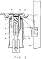
- Fig. 2 is a cross-sectional view showing an indirectly heated type cathode assembly according to one embodiment of the present invention; and
- Fig. 3 shows characteristic curves representing a change in the cutoff voltage of each strap which is used in a conventional, indirectly heated type cathode assembly and an indirectly heated type cathode assembly of the present invention.
- An indirectly heated type cathode assembly and its associated electron gun structure according to one embodiment of the present invention are shown in Fig. 2.
- In Fig. 2,
reference numeral 7 shows a cathode sleeve made of tantalum. Aheater 8 is provided within thecathode sleeve 7 and is of a coil type. A primary coil at an area A in Fig. 2 is wound at a finer pitch on the heater portion than the rest of the heater. In this embodiment, the area A is wound at a rate of the pitch about 1/3 that of the rest of the heater. - A cup 9 which is made of tantalum is fitted into an open upper end of the
cathode sleeve 7. An emitter-impregnatedtype cathode disc 10 is fitted into the cup 9 and obtained by impregnating a porous tungsten (W) substrate of about 20% in porosity with an electron emissive material. An iridium (Ir)-tungsten (W) alloy layer is formed on the surface of thecathode disc 10. - The insulation degradation of the
heater 8 occurs due to the scattering of vapor-phase deposits of the emitter material, such as Ba, from thecathode disc 10 toward theheater 8. In order to prevent such scattering, the cup 9 is fitted into the open upper end of thecathode sleeve 7. - Outside the
cathode sleeve 7, acylindrical holder 11 is provided coaxial with thecathode sleeve 7 such that it is spaced a predetermined distance apart from thecathode sleeve 7. Thecathode sleeve 7 is supported by theholder 11 through a plurality of strip-like straps 12, for example, three straps. In this case, thestrap 12 is connected at one end to the lower end portion of thecathode sleeve 7 and at the other end to the upper end of theholder 11. - From the test results it has been found that the
strap 12, if being made of, for example, a Ta-10%W alloy, Ta-3%W alloy, Ta-8%W-2%Hf alloy or Ta-10%W-2.5%Hf, reveals a high heat resistance and low-heat conduction. The other characteristics as obtained as the result of the tests are as shown in Table 1 below:
- As seen from the Table 1, 2.5 to 12.5% of W in Ta or 2 to 5% of Hf in Ta in the chemical compositions of the samples are preferable, all of which are percent by weight. Between the
cathode sleeve 7 and theholder 11, aheat reflecting cylinder 13 is located coaxial with thecathode sleeve 7 andholder 11 and supported relative to the upper end of theholder 11 by a plurality of support members such assupport pieces 14. Thesupport pieces 14 are L-shaped in cross-section. - As the support member, use may be made of not only the
support pieces 14 but also an annular support member. Or it may be possible to strike a portion of the heat reflecting cylinder, as a struck-out portion, out of itself or upset the heat reflecting cylinder by a press to provide a flange portion. - As seen from Fig. 2, the
strap 12 for supporting thecathode sleeve 7 is located such that it is not in contact with theheat reflecting cylinder 13. That is, thestrap 12 extends below theheat reflecting cylinder 13 with a major portion parallel to the axis of thecylinder 13, and is welded to the upper end of theholder 11. - A
first grid 15 is located in front of the indirectly-heated cathode assembly thus configured, so that it is spaced a predetermined distance apart from the cathode assembly. The peripheral portion of thefirst grid 15 is embedded in aninsulation support 16 made of glass. One end of a fixing or securingpiece 17 is mounted on the outer peripheral portion of theholder 11. The other end of thesecuring piece 17 is embedded into theinsulation support 16. - In this case, the
cathode disc 10 is hidden, by theheat reflecting cylinder 13, from view at at least that portion (a portion indicated by B in Fig. 2) of the insulation support which is defined between the embedded spot of thefirst grid 15 and that of thesecuring piece 17. - As a result, the
heat reflecting cylinder 13 is provided between thecathode sleeve 7 and theholder 11 to shield vapor deposits of the emitter material coming from thecathode disc 10. By so doing, it is possible to prevent vapor deposition of the emitter material on the insulation support and stem section of electron guns. This improves the withstand voltage characteristic and stray emission characteristic of a color CRT. - The indirectly-heated type cathode assembly according to this embodiment has a
heat reflecting cylinder 13 and employs a low heat conduction material for thestrap 12. Furthermore, theheater 8 is of a variable pitch type and hence provides an electric power-saving structure. - Thus, the heat reflecting cylinder (13) is arranged between the cathode sleeve (7) and the straps (12) such that it is in a non-contact position in relation to the sleeve and the straps. One open end of the heat reflecting cylinder (13) is located near a position corresponding to that of the cathode disc (10), while the other open end of the heat reflecting cylinder (13) extends up to the vicinity of the position where the straps (12) and the cathode sleeve (7) are joined together. Under the above conditions, heat radiated from the body of the cathode sleeve (7) is reflected by the heat reflecting cylinder (13), improving the efficiency with which the cathode disc (10), located in the upper part of the cathode sleeve (7), is heated. Since the straps (12) are located outside the heat reflecting cylinder (13), and are joined to the lower part of the cathode sleeve (7) whose temperature is relatively low, the temperature of the straps (12) is not increased significantly, with the result that the deformation of the straps (12) due to heat does not easily occur.
- By so doing, the dissipation power has only to be about one-third that of the conventional assembly shown in Fig. 1, noting that the invention is 0.7 W and the conventional assembly is 2 W. Therefore, the indirectly heated cathode assembly of the present invention can be mounted on an oxide cathode-incorporated CRT without the need of altering an associated circuit.
- The result of electric power saving leads to a lowering in heater temperature and an improved heater-to-sleeve withstand voltage characteristic, noting that, under an artificially harsh test, conventional assembly could perform up to 600 V but the present invention could perform up to 1200 V.
- According to the present invention, the cathode degradation resulting from ion impact can be prevented during the manufacture of a color CRT. That is, at the exhaust and high-voltage aging steps of the color CRT, discharge occurs across the
first grid 15 and thecathode disc 10. Due to such discharge, the cathode is subject to ion impact, causing defective emission. - In this embodiment, however, owing to the presence of the heat reflecting cylinder, discharge is produced across the forward end of the
heat reflecting cylinder 13 and thefirst grid 15, causing no loss in thecathode disc 10. - According to the present invention, since the material for the strap allows an improved heat resistance, it is possible to improve, for example, the degraded brightness and color drift of the color CRT.
- That is, a change in the dimension of Ggl-K (a gap between the first grid and the cathode surface), if being caused for some reason or other, results in a change in the cutoff voltage and hence a change in the anode current.
- For the color CRT, the cutoff voltage of the red, green and blue electron guns is so controlled as to develop predetermined color.
- However, the prolonged use of the color CRT causes the deformation of the associated component parts resulting from their fatigue by heat, thus giving rise to the dimensional change of Gg1-K. Since the dimensional change is not constant for the red, green and blue electron guns, anode current which is incident to the phosphor screen varies, thus producing a color drift and degraded brightness.
- In order to evaluate a possible dimensional change for a different strap material, tests were conducted to allow the indirectly-heated type cathode assembly of Fig. 2 to cool after being heated. The tests were repetitively conducted at a cathode temperature of 1150°C with the cathode assembly ON for five minutes and OFF for 10 minutes. The dimensional change between the cathode and the first grid is proportional to a change in the cutoff voltage and, therefore, the deformation of the strap can relatively precisely be measured by measuring the change in the cutoff voltage. In this way, measurement was made of the change in the cutoff voltage.
- Since a slow change occurred under the normal operation temperature condition, the cathode was caused to be heated at 1150°C and, after a stable condition was reached, allowed to cool. Such operations were repeated to examine a change in the cutoff voltage. Fig. 3 shows a change in the cutoff voltage for the case of a conventional tantalum strap and an alloy strap of the present invention, noting that the numerals in Fig. 3 correspond to those in Table 1.
- As seen from Fig. 3, a change in the cutoff voltage emerges, after 1000 times ON-OFF tests, for the case of the conventional tantalum strap and almost no change in the cutoff voltage emerges over a very long period of time, for the case of the alloy strap of the present invention, in which the ON-OFF tests were conducted under the same condition.
- Furthermore, the cathode was caused to be heated up to 1250°C, but a very small change in the cutoff voltage occurred. Hence the strap of the present invention revealed a very small change over a very long period even after many ON-OFF tests.
- According to the present invention, the strap reveals an improved heat resistance and allows its smaller cross-section. It is thus possible to prevent deformation of the strap by heat.
- That is, the conventional strap was 0.025 mm² in cross-section and the strap of the present invention can reduce its cross-section to 0.01 mm² in terms of using a heat resistant alloy, ensuring a power saving of 0.2 W (30% of full power).
- As already set forth above, the indirectly-heated type cathode assembly of the present invention has the heat reflecting cylinder which is not in contact with the cathode sleeve, heat radiation near the cathode disc is suppressed, ensuring an enhanced cathode heat efficiency.
- Furthermore, the heat reflecting cylinder shields a vapor-phase deposition of the emitter material from the cathode disc onto the insulation support and stem section of the electron guns, thus improving the withstand voltage characteristic and stray emission characteristic of the color CRT.
- Since the strap is made of analogy of a Ta-W alloy or Ta-W-Hf alloy, it is possible to prevent heat deformation and to obtain an enhanced heat resistant unit. As a result, if the indirectly heated type cathode assembly is used for a color CRT, it is possible to prominently improve degraded brightness, color drift and the other characteristics of the color CRT. According to the present invention, it is possible to enhance the heat resistance of the strap and to obtain a compact strap and hence contribute to power economy.
- The cathode disc is not restricted to the emitter impregnated type.
Claims (1)
- An indirectly heated type cathode assembly comprising a cathode sleeve (7) having a heater (8) within itself and having an emitter-impregnated cathode disc (10) fitted at one end thereof, a plurality of straps (12) connected at one end to a lower end portion of the cathode sleeve (7) ;
a cylindrical holder (11) whose upper end is connected to the other end of each strap (12), the holder (11) being coaxially located outside the cathode sleeve (7) such that it is spaced a predetermined distance apart from the cathode sleeve (7) ; and
a heat reflecting cylinder (13) coaxially located between the cathode sleeve (7) and the holder (11);
characterized in that:
the heat reflecting cylinder (13) is supported by the holder (11);
the heat reflecting cylinder (13) is arranged between the cathode sleeve (7) and the straps (12) so as to be in a non-contact position in relation to the cathode sleeve (7) and the straps (12); and
the heat reflecting cylinder (13) has two open ends, one of which is located near a position corresponding to the cathode disc (10), and the other of which extends up to the vicinity of the position where the straps (12) and the cathode sleeve (7) are joined together.
Applications Claiming Priority (2)
| Application Number | Priority Date | Filing Date | Title |
|---|---|---|---|
| JP318238/88 | 1988-12-16 | ||
| JP31823888A JP2607654B2 (en) | 1988-12-16 | 1988-12-16 | Indirectly heated cathode structure and electron gun structure using the same |
Publications (3)
| Publication Number | Publication Date |
|---|---|
| EP0373511A2 EP0373511A2 (en) | 1990-06-20 |
| EP0373511A3 EP0373511A3 (en) | 1990-11-22 |
| EP0373511B1 true EP0373511B1 (en) | 1995-09-06 |
Family
ID=18096969
Family Applications (1)
| Application Number | Title | Priority Date | Filing Date |
|---|---|---|---|
| EP89122590A Expired - Lifetime EP0373511B1 (en) | 1988-12-16 | 1989-12-07 | Indirectly heated cathode assembly. |
Country Status (6)
| Country | Link |
|---|---|
| US (1) | US5027029A (en) |
| EP (1) | EP0373511B1 (en) |
| JP (1) | JP2607654B2 (en) |
| KR (1) | KR920007411B1 (en) |
| CN (1) | CN1020058C (en) |
| DE (1) | DE68924137T2 (en) |
Families Citing this family (13)
| Publication number | Priority date | Publication date | Assignee | Title |
|---|---|---|---|---|
| KR930008611B1 (en) * | 1991-06-13 | 1993-09-10 | 삼성전관 주식회사 | Impregnated Cathode Structure and Manufacturing Method Thereof |
| KR930005377Y1 (en) * | 1991-09-26 | 1993-08-16 | 주식회사 금성사 | Structure frame for electron tube |
| JP3189388B2 (en) * | 1992-05-22 | 2001-07-16 | ソニー株式会社 | Cathode structure of cathode ray tube |
| KR200152895Y1 (en) * | 1995-06-21 | 1999-08-02 | 손욱 | Holder for electron gun |
| TW314638B (en) * | 1995-12-05 | 1997-09-01 | Thomson Tubes & Displays | |
| JPH11500863A (en) * | 1995-12-11 | 1999-01-19 | フィリップス エレクトロニクス ネムローゼ フェンノートシャップ | Cathode ray tube with heating element |
| JP2000516387A (en) * | 1997-06-03 | 2000-12-05 | コーニンクレッカ フィリップス エレクトロニクス エヌ ヴィ | Image display device having means for dissipating heat generated by a cathode |
| JP3798551B2 (en) * | 1998-04-23 | 2006-07-19 | 東芝電子エンジニアリング株式会社 | Color cathode ray tube |
| US20030025435A1 (en) * | 1999-11-24 | 2003-02-06 | Vancil Bernard K. | Reservoir dispenser cathode and method of manufacture |
| FR2810789A1 (en) | 2000-06-21 | 2001-12-28 | Thomson Tubes & Displays | Cathode for electron gun includes reflective skirt beneath heating filament to direct heat energy on to emissive element |
| FR2810790B1 (en) * | 2000-06-21 | 2002-10-04 | Thomson Tubes & Displays | CATHODE FOR REDUCED OVERALL CATHODE RAY TUBE |
| US9076625B2 (en) * | 2011-04-08 | 2015-07-07 | Varian Semiconductor Equipment Associates, Inc. | Indirectly heated cathode cartridge design |
| CN110931328B (en) * | 2019-12-06 | 2022-04-19 | 中国电子科技集团公司第十二研究所 | Cathode heater assembly |
Family Cites Families (12)
| Publication number | Priority date | Publication date | Assignee | Title |
|---|---|---|---|---|
| US3626231A (en) * | 1969-03-05 | 1971-12-07 | Sylvania Electric Prod | Thermal shunt for a cathode structure |
| US3681643A (en) * | 1970-10-15 | 1972-08-01 | Philips Corp | Cathode-system in which the cathode is supported by prestressed wires |
| JPS5340267A (en) * | 1976-09-27 | 1978-04-12 | Toshiba Corp | Electron gun assembling body |
| JPS5726514Y2 (en) * | 1977-03-25 | 1982-06-09 | ||
| US4101801A (en) * | 1977-04-28 | 1978-07-18 | Gte Sylvania Incorporated | Shielded cathode support structure |
| JPS5566819A (en) * | 1978-11-15 | 1980-05-20 | Hitachi Ltd | Oxide cathode for electron tube |
| JPS6036056B2 (en) * | 1979-06-21 | 1985-08-17 | 株式会社東芝 | cathode structure |
| NL8002343A (en) * | 1980-04-23 | 1981-11-16 | Philips Nv | ELECTRON GUN AND CATHODE JET CONTAINING SUCH ELECTRON GUN. |
| JPS5726514A (en) * | 1980-07-19 | 1982-02-12 | Iseki Agricult Mach | Sweet potato harvester |
| JPS5933146A (en) * | 1982-08-18 | 1984-02-22 | Mitsubishi Heavy Ind Ltd | Damping device |
| JPH0512909Y2 (en) * | 1985-09-28 | 1993-04-05 | ||
| DE3751168T2 (en) * | 1986-12-19 | 1995-10-19 | Toshiba Kawasaki Kk | Structure of an indirectly heated cathode for cathode ray tubes. |
-
1988
- 1988-12-16 JP JP31823888A patent/JP2607654B2/en not_active Expired - Fee Related
-
1989
- 1989-10-31 CN CN89108330A patent/CN1020058C/en not_active Expired - Fee Related
- 1989-11-24 KR KR1019890017125A patent/KR920007411B1/en not_active Expired
- 1989-12-07 DE DE68924137T patent/DE68924137T2/en not_active Expired - Fee Related
- 1989-12-07 EP EP89122590A patent/EP0373511B1/en not_active Expired - Lifetime
- 1989-12-08 US US07/447,904 patent/US5027029A/en not_active Expired - Lifetime
Also Published As
| Publication number | Publication date |
|---|---|
| KR920007411B1 (en) | 1992-08-31 |
| JP2607654B2 (en) | 1997-05-07 |
| EP0373511A3 (en) | 1990-11-22 |
| DE68924137D1 (en) | 1995-10-12 |
| CN1020058C (en) | 1993-03-10 |
| JPH02165545A (en) | 1990-06-26 |
| KR900010846A (en) | 1990-07-09 |
| DE68924137T2 (en) | 1996-02-01 |
| CN1043586A (en) | 1990-07-04 |
| US5027029A (en) | 1991-06-25 |
| EP0373511A2 (en) | 1990-06-20 |
Similar Documents
| Publication | Publication Date | Title |
|---|---|---|
| US5027029A (en) | Indirectly heated cathode assembly and its associated electron gun structure | |
| US4185223A (en) | Electron gun structure | |
| EP1133784B1 (en) | X-ray tube providing variable imaging spot size | |
| US4403169A (en) | Cathode suspension means for cathode ray tube electron gun | |
| US3983443A (en) | Vacuum electron device having directly-heated matrix-cathode-heater assembly | |
| US2032179A (en) | Oxide coated cathode for heavy duty service | |
| US3005123A (en) | Electron gun construction | |
| US4990823A (en) | Electron gun and method of manufacturing an electron gun, and display tube comprising such an electron gun | |
| US3883767A (en) | Heater for fast warmup cathode | |
| CA1215102A (en) | Cathode-ray tube and gettering device | |
| US4954745A (en) | Cathode structure | |
| JPH05325816A (en) | Cathode body structure for cathode-ray tube | |
| US2892115A (en) | Cathode structures | |
| KR200155630Y1 (en) | Cathode Structure for Cathode Ray Tube | |
| US3881126A (en) | Fast warm-up cathode assembly | |
| KR100740288B1 (en) | Electron gun and cathode-ray tube receiver | |
| US3361922A (en) | Cathode-grid assembly with means for preventing the formation of electron emissive materials upon the grid element | |
| KR0139639Y1 (en) | Cathode ray tube | |
| US5001389A (en) | Cathode-ray tube having arc suppressing means therein | |
| KR100209617B1 (en) | Heater for cathode-ray tube | |
| US7078851B2 (en) | Cathode ray tube | |
| US6492765B1 (en) | Cathode structure for cathode ray tube | |
| JPH07114103B2 (en) | Impregnated cathode assembly | |
| JPS586141Y2 (en) | Cathode structure of triode X-ray tube | |
| KR920004302Y1 (en) | Cathode structure of electron gun in crt |
Legal Events
| Date | Code | Title | Description |
|---|---|---|---|
| PUAI | Public reference made under article 153(3) epc to a published international application that has entered the european phase |
Free format text: ORIGINAL CODE: 0009012 |
|
| 17P | Request for examination filed |
Effective date: 19900104 |
|
| AK | Designated contracting states |
Kind code of ref document: A2 Designated state(s): DE FR GB |
|
| PUAL | Search report despatched |
Free format text: ORIGINAL CODE: 0009013 |
|
| AK | Designated contracting states |
Kind code of ref document: A3 Designated state(s): DE FR GB |
|
| 17Q | First examination report despatched |
Effective date: 19930521 |
|
| GRAA | (expected) grant |
Free format text: ORIGINAL CODE: 0009210 |
|
| AK | Designated contracting states |
Kind code of ref document: B1 Designated state(s): DE FR GB |
|
| REF | Corresponds to: |
Ref document number: 68924137 Country of ref document: DE Date of ref document: 19951012 |
|
| ET | Fr: translation filed | ||
| PLBE | No opposition filed within time limit |
Free format text: ORIGINAL CODE: 0009261 |
|
| STAA | Information on the status of an ep patent application or granted ep patent |
Free format text: STATUS: NO OPPOSITION FILED WITHIN TIME LIMIT |
|
| 26N | No opposition filed | ||
| REG | Reference to a national code |
Ref country code: GB Ref legal event code: 746 Effective date: 19980929 |
|
| REG | Reference to a national code |
Ref country code: FR Ref legal event code: D6 |
|
| REG | Reference to a national code |
Ref country code: GB Ref legal event code: IF02 |
|
| PGFP | Annual fee paid to national office [announced via postgrant information from national office to epo] |
Ref country code: DE Payment date: 20061130 Year of fee payment: 18 |
|
| PGFP | Annual fee paid to national office [announced via postgrant information from national office to epo] |
Ref country code: GB Payment date: 20061206 Year of fee payment: 18 |
|
| PGFP | Annual fee paid to national office [announced via postgrant information from national office to epo] |
Ref country code: FR Payment date: 20061208 Year of fee payment: 18 |
|
| GBPC | Gb: european patent ceased through non-payment of renewal fee |
Effective date: 20071207 |
|
| PG25 | Lapsed in a contracting state [announced via postgrant information from national office to epo] |
Ref country code: DE Free format text: LAPSE BECAUSE OF NON-PAYMENT OF DUE FEES Effective date: 20080701 |
|
| REG | Reference to a national code |
Ref country code: FR Ref legal event code: ST Effective date: 20081020 |
|
| PG25 | Lapsed in a contracting state [announced via postgrant information from national office to epo] |
Ref country code: GB Free format text: LAPSE BECAUSE OF NON-PAYMENT OF DUE FEES Effective date: 20071207 |
|
| PG25 | Lapsed in a contracting state [announced via postgrant information from national office to epo] |
Ref country code: FR Free format text: LAPSE BECAUSE OF NON-PAYMENT OF DUE FEES Effective date: 20071231 |