EP0372741B1 - Security system for a vehicle - Google Patents
Security system for a vehicle Download PDFInfo
- Publication number
- EP0372741B1 EP0372741B1 EP89311988A EP89311988A EP0372741B1 EP 0372741 B1 EP0372741 B1 EP 0372741B1 EP 89311988 A EP89311988 A EP 89311988A EP 89311988 A EP89311988 A EP 89311988A EP 0372741 B1 EP0372741 B1 EP 0372741B1
- Authority
- EP
- European Patent Office
- Prior art keywords
- vehicle
- electronic control
- control unit
- security system
- signal
- Prior art date
- Legal status (The legal status is an assumption and is not a legal conclusion. Google has not performed a legal analysis and makes no representation as to the accuracy of the status listed.)
- Expired - Lifetime
Links
Images
Classifications
-
- F—MECHANICAL ENGINEERING; LIGHTING; HEATING; WEAPONS; BLASTING
- F02—COMBUSTION ENGINES; HOT-GAS OR COMBUSTION-PRODUCT ENGINE PLANTS
- F02P—IGNITION, OTHER THAN COMPRESSION IGNITION, FOR INTERNAL-COMBUSTION ENGINES; TESTING OF IGNITION TIMING IN COMPRESSION-IGNITION ENGINES
- F02P11/00—Safety means for electric spark ignition, not otherwise provided for
- F02P11/04—Preventing unauthorised use of engines
-
- B—PERFORMING OPERATIONS; TRANSPORTING
- B60—VEHICLES IN GENERAL
- B60R—VEHICLES, VEHICLE FITTINGS, OR VEHICLE PARTS, NOT OTHERWISE PROVIDED FOR
- B60R25/00—Fittings or systems for preventing or indicating unauthorised use or theft of vehicles
- B60R25/01—Fittings or systems for preventing or indicating unauthorised use or theft of vehicles operating on vehicle systems or fittings, e.g. on doors, seats or windscreens
- B60R25/04—Fittings or systems for preventing or indicating unauthorised use or theft of vehicles operating on vehicle systems or fittings, e.g. on doors, seats or windscreens operating on the propulsion system, e.g. engine or drive motor
-
- G—PHYSICS
- G07—CHECKING-DEVICES
- G07C—TIME OR ATTENDANCE REGISTERS; REGISTERING OR INDICATING THE WORKING OF MACHINES; GENERATING RANDOM NUMBERS; VOTING OR LOTTERY APPARATUS; ARRANGEMENTS, SYSTEMS OR APPARATUS FOR CHECKING NOT PROVIDED FOR ELSEWHERE
- G07C5/00—Registering or indicating the working of vehicles
- G07C5/08—Registering or indicating performance data other than driving, working, idle, or waiting time, with or without registering driving, working, idle or waiting time
- G07C5/0808—Diagnosing performance data
Definitions
- the invention relates to security systems for vehicles.
- a thief In devising or evaluating a security system it is useful to consider the ways in which a thief would intend to by-pass or neutralise a security system because the degree of difficulty for the thief is a measure of the effectiveness of the security system.
- Some forms of security systems inhibit supply of electrical power to a vehicle ignition system, thus preventing the vehicle from being driven off.
- One way for a thief to overcome such a system is to hot-wire the vehicle, that is to provide an independent source of power supply to the ignition system. This can require nothing more than by-passing the security device.
- a security system which can not be by-passed by hot-wiring clearly constitutes a step forward.
- FR-A-2613993 which forms the preamble of claim 1
- FR-A-2545632 each disclose a vehicle security system in which a signal from a hand held transmitter is received and checked by a first microprocessor unit, which, if the signal is correct, sends a signal to a control unit which checks that signal and, if it is correct, enables a function of the vehicle.
- An object of the invention is to provide a vehicle with an improved form of security system.
- a security system for a vehicle powered by an internal combustion engine having a vital function comprising a signal unit which can be operated by an authorised user to send a coded vital function enable signal and a first electronic control unit (hereinafter referred to as first ECU) for generating a control signal which drives the vital function, characterized in that the system further comprises a second electronic control unit, hereinafter referred to as second ECU, and in that the first ECU and the second ECU form a mutually compatible pair in that the first ECU is, upon receipt of the coded vital function enable signal, not operative to generate the control signal until a parity check has been effected between the first ECU and the second ECU.
- first ECU first electronice control unit
- second ECU second electronice control unit
- the first ECU may be an engine ECU.
- the vital function is normally the generation of appropriately timed and routed sparks for a spark ignition engine.
- the vital function controlled may be the supply of and metering of fuel.
- the enable signal may be a mutli-bit binary signal which may be generated in a variety of ways. For example, it could be generated as a password or number code to be entered from a keyboard; the controls of a trip computer or even a radio or radio cassette player could provide the keyboard for such an operation.
- an infrared or ultrasonic generator issuing a coded signal may be employed to transmit a suitable signal to the first ECU.
- An ultra sonic or infra red signal generator may also act as a remote controller for locking and unlocking the vehicle doors.
- the second ECU may for example be incorporated in an audio entertainment unit or in a vehicle trip computer or may comprise a security ECU housed in an inaccessible position within the vehicle.
- more than two ECUs may be matched together by parity coding in a mutually compatible group.
- interrogation of compatibility codes and setting of a compatible code in any replacement ECU or code checking means which is needed during the life of a vehicle should be possible but interrogation and code setting should be password or similarly protected.
- passwords could be incorporated within immobile diagnostic equipment located in ECU or code checking means which is needed during the life of a vehicle should be possible but interrogation and code setting should be password or similarly protected.
- passwords could be incorporated within immobile diagnostic equipment located in secure service locations or they could be known to only a small number of carefully security screened personnel.
- a combination of passwords known to personnel and stored in diagnostic equipment would provide even greater overall security for the system, particularly if each diagnostic equipment requires for operation a different password known only to a very small number of personnel with high security clearance.
- the system may also respond to a master password known only to the vehicle manufacturer.
- the security system may also incorporate an alarm to be triggered by any of the criteria normally used for triggering an alarm. Examples are physical movement of the vehicle, opening of vehicle doors, infra red detectors and ultra sonic detectors. Typically detection of a feature which could cause an alarm does not trigger the alarm until after a time delay, giving authorised personnel sufficient time to disable the alarm before it is triggered.
- An alarm signal of this kind may give an audible warning or a flashing light warning as its alarm signal.
- an alarm signal generated in this way may also be fed to the first ECU, disabling the vital function for the engine.
- the enabling signal is provided by a keyboard input or other direct but inconvenient action by a vehicle user
- the user may have the choice of setting or leaving unset a high level of security or in an alternative system of leaving set or overriding the setting of the security system.
- the setting or overriding operation may be effected by keying in a simple code immediately before or immediately after switching off the engine.
- the code keyed in on switching off the vehicle may be the same code as is needed subsequently to re-start the vehicle.
- one of the ECUs includes a storage facility which can not readily be overwritten or erased and which incorporates a unique security code associated with the vehicle.
- the unique code could be the vehicle identification number (VIN) which is attriubted to each vehicle on manufacture and is normally marked visibly on the vehicle.
- VIN vehicle identification number
- it could be a registration number installed by a dealer on registration of the vehicle.
- it could be a code capable of translation into the VIN or registration number or a code number readily identifiable therewith.
- Each dealer should be provided with a diagnostic unit capable of reading and displaying the sorted security code or at least of indicating compatibility when compared with a standard number such as the VIN or registration number when transmitted to the ECU.
- the records could also identify written off but subsequently repaired vehicles allowing some check on the history of a used vehicle.
- box V intended diagrammatically to represent the vehicle.
- box T represents diagnostic test equipment normally installed in a vehicle servicing facility.
- the vehicle is driven by a multi-cylinder spark-ignition internal combustion engine 11 having spark plugs 12 to which ignition sparks are provided from a high tension circuit 13.
- Operation of the engine is controlled by a first electronic control unit in the form of an engine ECU 14 which receives signals monitoring current engine operating conditions from the engine and from external controls such as accelerator pedal and supplies signals to the engine to control its functions.
- line 15 is shown supplying spark generation and timing signals to the high tension circuitry of the engine.
- the high tension circuit is such that it can not generate sparks for operation of the engine without the presence of the signal on line 15; ie. the signal does not merely provide a fine tuning signal for spark timing, it actually causes each individual spark to be generated.
- Spark generation is a vital function for engine operation and the signal on line 15 drives this function in such a way that without the signal the vital function is disabled.
- a key operated ignition switch 16 can be operated by a vehicle driver in the usual way to power up the first (engine) ECU 14 when it is desired to start the engine and drive the vehicle away.
- a start up procedure is initiated on powering up the first (engine) ECU and during this powering up procedure certain checks are carried out by the engine ECU. A total of three such checks will be described.
- One check is based on receipt of a correctly coded infrared signal.
- the vehicle is equipped with an infrared signal receiver 17 and an associated decoder 18.
- the decoder 18 is such as to decode the signal supplied by an infrared "key" 20, to compare the decoded signal with a stored value in the decoder and issue output signals if but only if there is parity between the received infrared signal and the stored value. Receipt of a valid infrared signal provides an output signal to the door locks 19 to unlock the vehicle doors.
- the decoded signal itself is also supplied to the first (engine) ECU 14 where it is compared by a parity check with a security code stored at 21 in the first (engine) ECU 14. The enabling output from the parity check may be initiated on unlocking the door.
- the first (engine) ECU 14 is also connected to a second ECU 22 which in this case forms part of a trip computer having an operating panel 23.
- the second ECU 22 has stored in it at 24 a code corresponding to the security code within the first (engine) ECU 14.
- the start up procedure includes interrogation of the second ECU 22 by the first (engine) ECU 14 to transmit the code from the second ECU 22 to the first engine ECU 14.
- the codes stored in both ECU 14,22 are compared with each other for compatibility and a spark enable signal is produced only after parity is established.
- a further possible check involves use of the control panel 23 of the trip computer 22 as a keyboard.
- a predetermined code has to be keyed in to the trip computer keyboard 23 and compared with the code stored in the first (engine) ECU 14 for parity before a spark signal is enabled.
- the arrangement is such that the spark signal is enabled only if all of the security checks which are deployed show parity.
- An electrical connector 25 communicating with the first (engine) ECU 14 allows the electronic system of the vehicle to be interconnected with a diagnostic test unit T.
- This unit T also incorporates a connector 26 permitting interconnection to the vehicle.
- the diagnostic test unit can be considered as a computer 27 having a display 28 and a keyboard 29.
- the test unit is used during routine vehicle servicing to check a wide range of functions in the vehicle, most of which are of no significance to the present invention.
- an operator After interconnecting the test unit and the vehicle, an operator has to identify the vehicle being serviced so that various parameters in the test procedure are set correctly. This identification may conveniently be effected by keying in to the keyboard 29 the vehicle identification number which can be read directly from an inscription on the vehicle.
- An alternative is to attach the VIN to the vehicle by means of a bar code and to read it with a bar code reader. The VIN is displayed on a screen 28.
- the VIN code is also stored at 31 in the first (engine) ECU 14.
- One test procedure is for the first (engine) ECU 14 to be interrogated by the computer 27 to read out the stored VIN code. This may be displayed alongside the keyed in VIN code for comparison purposes. Alternatively or in addition the computer 27 may be programmed to compare the VIN codes.
- the VIN code may also be stored in the second ECU 22 in which case this unit is also interrogated.
- the operator is alerted to an irregularity. If the irregularity can not be explained by any other means, it is probably an indication that the vehicle has been tampered with, possibly indicating that it is a stolen vehicle with a disguised identity.
- the arrangement should be such that password protected access to the VIN codes is permissible, enabling an operator with high security clearance to change or at least inscribe a VIN number into an ECU.
Landscapes
- Engineering & Computer Science (AREA)
- Mechanical Engineering (AREA)
- Physics & Mathematics (AREA)
- General Physics & Mathematics (AREA)
- Chemical & Material Sciences (AREA)
- Combustion & Propulsion (AREA)
- General Engineering & Computer Science (AREA)
- Lock And Its Accessories (AREA)
- Auxiliary Drives, Propulsion Controls, And Safety Devices (AREA)
- Combined Controls Of Internal Combustion Engines (AREA)
- Control Of Vehicle Engines Or Engines For Specific Uses (AREA)
Description
- The invention relates to security systems for vehicles.
- It is normal practice to provide road vehicles with door locks, a lockable ignition switch (or equivalent for a diesel engine) and a lockable steering mechanism, the last two locks normally being combined. These features do not protect a vehicle completely against a determined thief who wishes to drive away the vehicle or remove contents or fittings from the vehicle. With a view to resisting unauthorised access to vehicles, some vehicles are fitted with alarms which give warning when a vehicle has been interfered with or with devices which resist entry to or operation of the vehicle. Systems incorporating security features going beyond the conventional door lock, starter/ignition switch lock and steering lock are known as security systems while the more basic security features common to virtually all vehicles are not normally classified as security systems.
- In devising or evaluating a security system it is useful to consider the ways in which a thief would intend to by-pass or neutralise a security system because the degree of difficulty for the thief is a measure of the effectiveness of the security system. Some forms of security systems inhibit supply of electrical power to a vehicle ignition system, thus preventing the vehicle from being driven off. One way for a thief to overcome such a system is to hot-wire the vehicle, that is to provide an independent source of power supply to the ignition system. This can require nothing more than by-passing the security device. A security system which can not be by-passed by hot-wiring clearly constitutes a step forward.
- FR-A-2613993, which forms the preamble of claim 1, and FR-A-2545632 each disclose a vehicle security system in which a signal from a hand held transmitter is received and checked by a first microprocessor unit, which, if the signal is correct, sends a signal to a control unit which checks that signal and, if it is correct, enables a function of the vehicle.
- An object of the invention is to provide a vehicle with an improved form of security system.
- According to the present invention there is provided a security system for a vehicle powered by an internal combustion engine having a vital function, the system comprising a signal unit which can be operated by an authorised user to send a coded vital function enable signal and a first electronic control unit (hereinafter referred to as first ECU) for generating a control signal which drives the vital function, characterized in that the system further comprises a second electronic control unit, hereinafter referred to as second ECU, and in that the first ECU and the second ECU form a mutually compatible pair in that the first ECU is, upon receipt of the coded vital function enable signal, not operative to generate the control signal until a parity check has been effected between the first ECU and the second ECU.
- The first ECU may be an engine ECU.
- The vital function is normally the generation of appropriately timed and routed sparks for a spark ignition engine. However, for a compression ignition engine or for a fuel injection spark ignition engine, the vital function controlled may be the supply of and metering of fuel.
- The enable signal may be a mutli-bit binary signal which may be generated in a variety of ways. For example, it could be generated as a password or number code to be entered from a keyboard; the controls of a trip computer or even a radio or radio cassette player could provide the keyboard for such an operation. Alternatively, an infrared or ultrasonic generator issuing a coded signal may be employed to transmit a suitable signal to the first ECU. An ultra sonic or infra red signal generator may also act as a remote controller for locking and unlocking the vehicle doors.
- With such an arrangement, a would be thief is thwarted even if he or she introduces a replacement ECU which is pre-enabled or for which the thief can generate the correct enable signal.
- The second ECU may for example be incorporated in an audio entertainment unit or in a vehicle trip computer or may comprise a security ECU housed in an inaccessible position within the vehicle.
- For even greater security, more than two ECUs may be matched together by parity coding in a mutually compatible group.
- As service backup for vehicles fitted with a security system of this nature, interrogation of compatibility codes and setting of a compatible code in any replacement ECU or code checking means which is needed during the life of a vehicle should be possible but interrogation and code setting should be password or similarly protected. For example, passwords could be incorporated within immobile diagnostic equipment located in ECU or code checking means which is needed during the life of a vehicle should be possible but interrogation and code setting should be password or similarly protected. For example, passwords could be incorporated within immobile diagnostic equipment located in secure service locations or they could be known to only a small number of carefully security screened personnel. A combination of passwords known to personnel and stored in diagnostic equipment would provide even greater overall security for the system, particularly if each diagnostic equipment requires for operation a different password known only to a very small number of personnel with high security clearance. The system may also respond to a master password known only to the vehicle manufacturer.
- If a potential thief could acquire a matched pair or matched group of mutually compatible ECUs, he would be able to operate the vehicle by replacing all of the original ECUs by the new matched group. However, acquiring a matched group would be expensive and as matched groups would not normally be required for regular repair or servicing, their distribution could be prohibited or stringently controlled.
- The security system may also incorporate an alarm to be triggered by any of the criteria normally used for triggering an alarm. Examples are physical movement of the vehicle, opening of vehicle doors, infra red detectors and ultra sonic detectors. Typically detection of a feature which could cause an alarm does not trigger the alarm until after a time delay, giving authorised personnel sufficient time to disable the alarm before it is triggered. An alarm signal of this kind may give an audible warning or a flashing light warning as its alarm signal. In conjunction with the present invention, an alarm signal generated in this way may also be fed to the first ECU, disabling the vital function for the engine. With such an arrangement, a potential thief who manages to inhibit the audible or visible alarm signal and to provide the signal normally supplied by an authorised user is still prevented from driving the car unless he can provide the authorised enable signal within the delay period for operation of the alarm.
- In a case where the enabling signal is provided by a keyboard input or other direct but inconvenient action by a vehicle user, there may be provision to set or not set a high level of security at the choice of the vehicle user. For example, in stopping and parking a car in a secure garage, the user may have the choice of setting or leaving unset a high level of security or in an alternative system of leaving set or overriding the setting of the security system. The setting or overriding operation may be effected by keying in a simple code immediately before or immediately after switching off the engine. In a further variation, the code keyed in on switching off the vehicle may be the same code as is needed subsequently to re-start the vehicle.
- Preferably one of the ECUs includes a storage facility which can not readily be overwritten or erased and which incorporates a unique security code associated with the vehicle.
- The unique code could be the vehicle identification number (VIN) which is attriubted to each vehicle on manufacture and is normally marked visibly on the vehicle. As an alternative it could be a registration number installed by a dealer on registration of the vehicle. As a still further alternative it could be a code capable of translation into the VIN or registration number or a code number readily identifiable therewith.
- Each dealer should be provided with a diagnostic unit capable of reading and displaying the sorted security code or at least of indicating compatibility when compared with a standard number such as the VIN or registration number when transmitted to the ECU.
- Any incompatibility is likely to be indicative of a stolen vehicle, namely one in which the registration number or VIN has been altered to attempt to disguise the identity of the vehicle. This latter arrangement does not directly prevent or inhibit stealing of a vehicle but it diminishes the value of a vehicle which has been stolen.
- With all of the arrangements thus far described, it would still be possible for a thief to obtain a scrap vehicle, remove all of the ECUs, steal a vehicle of the same type and give the stolen vehicle the identity of the scrap vehicle. To guard against this, insurance companies or other responsible persons should either arrange for destruction of critical ECUs from scrapped vehicles or establish a record of the identification codes of vehicles which have been scrapped. An irregularity would then come to the attention of anyone servicing the vehicle and aware of or having a computer loaded with scrap vehicle data.
- The records could also identify written off but subsequently repaired vehicles allowing some check on the history of a used vehicle.
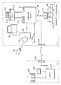
- An embodiment of the invention will be described with reference to the accompanying drawing which is a diagrammatic representation of a security system.
- Those elements which are carried on the vehicle are depicted within box V intended diagrammatically to represent the vehicle. A further box T represents diagnostic test equipment normally installed in a vehicle servicing facility.
- The vehicle is driven by a multi-cylinder spark-ignition
internal combustion engine 11 having spark plugs 12 to which ignition sparks are provided from ahigh tension circuit 13. Operation of the engine is controlled by a first electronic control unit in the form of an engine ECU 14 which receives signals monitoring current engine operating conditions from the engine and from external controls such as accelerator pedal and supplies signals to the engine to control its functions. Forexample line 15 is shown supplying spark generation and timing signals to the high tension circuitry of the engine. The high tension circuit is such that it can not generate sparks for operation of the engine without the presence of the signal online 15; ie. the signal does not merely provide a fine tuning signal for spark timing, it actually causes each individual spark to be generated. Spark generation is a vital function for engine operation and the signal online 15 drives this function in such a way that without the signal the vital function is disabled. - A key operated
ignition switch 16 can be operated by a vehicle driver in the usual way to power up the first (engine) ECU 14 when it is desired to start the engine and drive the vehicle away. A start up procedure is initiated on powering up the first (engine) ECU and during this powering up procedure certain checks are carried out by the engine ECU. A total of three such checks will be described. - One check is based on receipt of a correctly coded infrared signal. The vehicle is equipped with an infrared signal receiver 17 and an associated
decoder 18. Thedecoder 18 is such as to decode the signal supplied by an infrared "key" 20, to compare the decoded signal with a stored value in the decoder and issue output signals if but only if there is parity between the received infrared signal and the stored value. Receipt of a valid infrared signal provides an output signal to the door locks 19 to unlock the vehicle doors. The decoded signal itself is also supplied to the first (engine) ECU 14 where it is compared by a parity check with a security code stored at 21 in the first (engine) ECU 14. The enabling output from the parity check may be initiated on unlocking the door. - The first (engine) ECU 14 is also connected to a
second ECU 22 which in this case forms part of a trip computer having an operatingpanel 23. Thesecond ECU 22 has stored in it at 24 a code corresponding to the security code within the first (engine) ECU 14. The start up procedure includes interrogation of thesecond ECU 22 by the first (engine) ECU 14 to transmit the code from thesecond ECU 22 to the first engine ECU 14. The codes stored in bothECU 14,22 are compared with each other for compatibility and a spark enable signal is produced only after parity is established. - A further possible check involves use of the
control panel 23 of thetrip computer 22 as a keyboard. In conjunction with switching on the ignition, a predetermined code has to be keyed in to thetrip computer keyboard 23 and compared with the code stored in the first (engine) ECU 14 for parity before a spark signal is enabled. - The arrangement is such that the spark signal is enabled only if all of the security checks which are deployed show parity.
- An
electrical connector 25 communicating with the first (engine) ECU 14 allows the electronic system of the vehicle to be interconnected with a diagnostic test unit T. This unit T also incorporates aconnector 26 permitting interconnection to the vehicle. For the purposes of the present invention the diagnostic test unit can be considered as acomputer 27 having adisplay 28 and akeyboard 29. The test unit is used during routine vehicle servicing to check a wide range of functions in the vehicle, most of which are of no significance to the present invention. After interconnecting the test unit and the vehicle, an operator has to identify the vehicle being serviced so that various parameters in the test procedure are set correctly. This identification may conveniently be effected by keying in to thekeyboard 29 the vehicle identification number which can be read directly from an inscription on the vehicle. An alternative is to attach the VIN to the vehicle by means of a bar code and to read it with a bar code reader. The VIN is displayed on ascreen 28. - The VIN code is also stored at 31 in the first (engine) ECU 14. One test procedure is for the first (engine) ECU 14 to be interrogated by the
computer 27 to read out the stored VIN code. This may be displayed alongside the keyed in VIN code for comparison purposes. Alternatively or in addition thecomputer 27 may be programmed to compare the VIN codes. The VIN code may also be stored in thesecond ECU 22 in which case this unit is also interrogated. - If there is any disparity in the VIN codes, the operator is alerted to an irregularity. If the irregularity can not be explained by any other means, it is probably an indication that the vehicle has been tampered with, possibly indicating that it is a stolen vehicle with a disguised identity.
- Storage of the VIN codes in the
ECUs 14,22 is such that effecting changes is not possible by a normal service operative. - However, to cater for replacement of an ECU without introducing an irregularity into VIN codes, the arrangement should be such that password protected access to the VIN codes is permissible, enabling an operator with high security clearance to change or at least inscribe a VIN number into an ECU.
Claims (11)
- A security system for a vehicle (V) powered by an internal combustion engine (11) having a vital function (13), the system comprising a signal unit (18, 20, 23) which can be operated by an authorised user to send a coded vital function enable signal and a first electronic control unit (14) for generating a control signal which drives the vital function, characterized in that the system further comprises a second electronic control unit (22) and in that the first electronic control unit (14) and the second electronic control unit (22) form a mutually compatible pair in that the first electronic control unit (14) is, upon receipt of the coded vital function enable signal, not operative to generate the control signal until a parity check has been effected between the first electronic control unit (14) and the second electronic control unit (22).
- A security system as claimed in claim 1, characterized in that the parity check is effected between codes stored in the first electronic control unit (14) and in the second electronic control unit (22).
- A security system as claimed in claim 1, characterized in that the parity check is effected between the decoded vital function enable signal and codes stored in the first electronic control unit (14) and in the second electronic control unit (22).
- A security system as claimed in any one of claims 1 to 3, characterized in that the vital function is the generation of appropriately timed and routed sparks for a spark ignition engine (11).
- A security system as claimed any one of claims 1 to 3, characterized in that the vital function controlled is the supply of and/or metering of fuel to the engine.
- A security system as claimed in any one of claims 1 to 5, characterized in that the signal unit (18) is operated by an infrared or ultrasonic generator (20) issuing the coded vital function enable signal.
- A security system as claimed in any one of the preceding claims, characterized in that it also incorporates an alarm.
- A security system as claimed in claim 7, characterized in that an alarm signal generated by triggering the alarm is also fed to the first electronic control unit (14), disabling the vital function for the engine (11).
- A security system as claimed in any one of the preceding claims, characterized in that one of the electronic control units (14, 22) includes a storage facility which can not readily be overwritten or erased and which incorporates a unique security code associated with the vehicle.
- A security system as claimed in claim 9, characterized in that the unique security code is a vehicle identification number (VIN) which is attributed to the vehicle on manufacture and is marked visibly on the vehicle.
- A system as claimed in claim 9, characterized in that the unique security code is a code capable of translation into the vehicle identification number (VIN).
Applications Claiming Priority (2)
| Application Number | Priority Date | Filing Date | Title |
|---|---|---|---|
| GB8828244 | 1988-12-02 | ||
| GB8828244A GB2227791B (en) | 1988-12-02 | 1988-12-02 | Vehicle security system |
Publications (3)
| Publication Number | Publication Date |
|---|---|
| EP0372741A2 EP0372741A2 (en) | 1990-06-13 |
| EP0372741A3 EP0372741A3 (en) | 1992-01-02 |
| EP0372741B1 true EP0372741B1 (en) | 1996-01-17 |
Family
ID=10647896
Family Applications (1)
| Application Number | Title | Priority Date | Filing Date |
|---|---|---|---|
| EP89311988A Expired - Lifetime EP0372741B1 (en) | 1988-12-02 | 1989-11-20 | Security system for a vehicle |
Country Status (4)
| Country | Link |
|---|---|
| EP (1) | EP0372741B1 (en) |
| JP (1) | JPH02279429A (en) |
| DE (1) | DE68925471T2 (en) |
| GB (1) | GB2227791B (en) |
Families Citing this family (28)
| Publication number | Priority date | Publication date | Assignee | Title |
|---|---|---|---|---|
| DE69216644T2 (en) * | 1991-09-17 | 1997-04-24 | Ford Werke Ag | MOTOR VEHICLE SECURITY SYSTEM |
| DE4305361A1 (en) * | 1993-02-22 | 1994-08-25 | Siemens Ag | Method for ensuring the exclusive operation of devices and/or systems, in particular conveyor trucks, by authorised personnel |
| DE4427267C2 (en) * | 1993-09-11 | 2003-06-26 | Volkswagen Ag | Anti-theft device for a motor vehicle |
| US5583383A (en) * | 1993-10-29 | 1996-12-10 | Robert Bosch Gmbh | Vehicle security system |
| DE4338033C2 (en) * | 1993-11-08 | 2000-05-18 | Telefunken Microelectron | Anti-theft system for motor vehicles |
| DE69501206T2 (en) * | 1994-02-17 | 1998-05-28 | Rover Group | SECURITY SYSTEM FOR VEHICLES |
| JP2915299B2 (en) * | 1994-09-09 | 1999-07-05 | 本田技研工業株式会社 | Vehicle anti-theft device |
| US5633624A (en) * | 1994-09-22 | 1997-05-27 | Honda Giken Kogyo Kabushiki Kaisha | Vehicle anti-theft system |
| JP3001782B2 (en) * | 1994-09-28 | 2000-01-24 | 本田技研工業株式会社 | Engine control device for vehicle theft prevention |
| JP3005175B2 (en) * | 1994-09-28 | 2000-01-31 | 本田技研工業株式会社 | Vehicle anti-theft device |
| DE4437334C1 (en) * | 1994-10-19 | 1996-04-04 | Bosch Gmbh Robert | Service-friendly immobilizer |
| US5686883A (en) * | 1994-10-19 | 1997-11-11 | Honda Giken Kogyo Kabushiki Kaisha | Vehicle anti-theft system |
| JP2813962B2 (en) * | 1994-10-28 | 1998-10-22 | 本田技研工業株式会社 | Anti-theft device |
| JPH08133018A (en) * | 1994-11-09 | 1996-05-28 | Honda Motor Co Ltd | Engine control means with anti-theft device for vehicle anti-theft function |
| EP0719682B1 (en) * | 1994-12-28 | 2000-02-23 | Mazda Motor Corporation | Anti-vehicle-theft apparatus |
| JP2954845B2 (en) * | 1995-01-27 | 1999-09-27 | 本田技研工業株式会社 | Engine control device for vehicle theft prevention |
| JP2922821B2 (en) * | 1995-02-08 | 1999-07-26 | 本田技研工業株式会社 | Vehicle data processing method and device |
| JP3073904B2 (en) * | 1995-02-17 | 2000-08-07 | 本田技研工業株式会社 | Vehicle data processing device |
| JP2943976B2 (en) * | 1995-02-17 | 1999-08-30 | 本田技研工業株式会社 | Engine control device with vehicle anti-theft function |
| EP1398293A3 (en) | 1995-03-10 | 2005-02-09 | Michael C. Ryan | Fluid delivery control nozzle |
| DE19520505A1 (en) * | 1995-06-03 | 1996-12-05 | Bosch Gmbh Robert | Immobilizer |
| DE69609250T2 (en) * | 1995-07-05 | 2000-11-23 | Ford Motor Co., Dearborn | Release device for motor vehicles |
| DE19526530C1 (en) * | 1995-07-20 | 1996-08-14 | Siemens Ag | Vehicle immobiliser initialising system |
| DE19530720B4 (en) * | 1995-08-18 | 2004-07-22 | Kiekert Ag | central locking system |
| GB2309488A (en) * | 1996-01-27 | 1997-07-30 | Motorola Inc | Vehicle security arrangement |
| CN103171516B (en) * | 2013-04-11 | 2015-08-12 | 力帆实业(集团)股份有限公司 | A kind of engine theftproof system based on infrared technique |
| CN109398307B (en) * | 2017-08-18 | 2022-06-28 | 法雷奥汽车内部控制(深圳)有限公司 | Keyless entry and start system and method for improving security of keyless entry and start system |
| DE102019122731A1 (en) * | 2019-08-23 | 2021-02-25 | Bayerische Motoren Werke Aktiengesellschaft | Motor vehicle with information system |
Family Cites Families (9)
| Publication number | Priority date | Publication date | Assignee | Title |
|---|---|---|---|---|
| JPS54158532A (en) * | 1978-06-02 | 1979-12-14 | Nippon Denso Co Ltd | Burglarproof method and device for car |
| IL55057A (en) * | 1978-07-02 | 1984-01-31 | Zuck Or Ltd | Apparatus for preventing vehicle theft |
| DE2911160A1 (en) * | 1979-03-22 | 1980-10-02 | Daimler Benz Ag | DEVICE FOR PREVENTING UNAUTHORIZED STARTING OF VEHICLES |
| FR2533516B1 (en) * | 1982-09-24 | 1985-11-29 | Verine Jean Pierre | ANTI-THEFT SYSTEM FOR A MOTOR VEHICLE |
| FR2545632A1 (en) * | 1983-05-04 | 1984-11-09 | Radiotechnique | Anti-theft system comprising a main device and an "annex to be protected" element |
| GB8701388D0 (en) * | 1987-01-22 | 1987-02-25 | Delderfold Ltd | Vehicle security system |
| US4792792A (en) * | 1987-02-04 | 1988-12-20 | Costino Harold F | Anti-theft system for an automotive vehicle |
| FR2613993B1 (en) * | 1987-04-17 | 1992-01-03 | Renault | DEVICE AND METHOD FOR ELECTRONIC THEFT OF A VEHICLE |
| FR2646642B1 (en) * | 1989-05-05 | 1991-08-23 | Ferroud Plattet Jacques | ANTI-THEFT DEVICE FOR ALL VEHICLES |
-
1988
- 1988-12-02 GB GB8828244A patent/GB2227791B/en not_active Expired - Fee Related
-
1989
- 1989-11-20 EP EP89311988A patent/EP0372741B1/en not_active Expired - Lifetime
- 1989-11-20 DE DE68925471T patent/DE68925471T2/en not_active Expired - Fee Related
- 1989-12-01 JP JP1310849A patent/JPH02279429A/en active Pending
Also Published As
| Publication number | Publication date |
|---|---|
| DE68925471D1 (en) | 1996-02-29 |
| EP0372741A2 (en) | 1990-06-13 |
| GB2227791A (en) | 1990-08-08 |
| EP0372741A3 (en) | 1992-01-02 |
| GB8828244D0 (en) | 1989-01-05 |
| DE68925471T2 (en) | 1996-05-30 |
| GB2227791B (en) | 1993-07-28 |
| JPH02279429A (en) | 1990-11-15 |
Similar Documents
| Publication | Publication Date | Title |
|---|---|---|
| EP0372741A2 (en) | Security system for a vehicle | |
| EP0682608B1 (en) | Vehicle security system | |
| US4327353A (en) | Security system | |
| US6188326B1 (en) | Vehicle control system including token verification and code reset features | |
| EP0835790B1 (en) | Anti-theft device using code type transponder | |
| US5019812A (en) | Electronic locking system | |
| JP3514764B2 (en) | Vehicle safety device | |
| US5703413A (en) | Method for operating a vehicle security system including code comparison after starting which counts start attempts | |
| US6480117B1 (en) | Vehicle control system including token verification and code reset features for electrically connected token | |
| US20090237205A1 (en) | Method and system for securing a vehicle against theft | |
| HU221220B1 (en) | Immobilizer equipment for vehicles | |
| GB2326673A (en) | Vehicle anti-theft system in which fuelling of i.c. engine is controlled to prevent unauthorised operation | |
| JP3377267B2 (en) | Automotive engine starter | |
| EP0754606B1 (en) | Anti-theft device for a vehicle | |
| EP0586192A1 (en) | Electronic identification system with anti-tampering protection | |
| JPH01501930A (en) | vehicle security system | |
| CN100366474C (en) | biological measuring anti-theft device for motor vehicle | |
| US20020145535A1 (en) | Vehicle control system for a vehicle data communications bus and having verification features | |
| WO1994012372A1 (en) | Apparatus in an authorization checking system for vehicles | |
| US7486170B2 (en) | Vehicle antitheft device | |
| US6107695A (en) | Drive-away blocking device | |
| WO1996040538A1 (en) | Authorization system for supplemental restraint systems | |
| GB2094045A (en) | Vehicle having a security alarm system | |
| GB2269253A (en) | A security system | |
| CA2268201A1 (en) | Operator's license validation system |
Legal Events
| Date | Code | Title | Description |
|---|---|---|---|
| PUAI | Public reference made under article 153(3) epc to a published international application that has entered the european phase |
Free format text: ORIGINAL CODE: 0009012 |
|
| AK | Designated contracting states |
Kind code of ref document: A2 Designated state(s): DE ES FR GB IT |
|
| 17P | Request for examination filed |
Effective date: 19901217 |
|
| RAP1 | Party data changed (applicant data changed or rights of an application transferred) |
Owner name: ROVER GROUP LIMITED |
|
| PUAL | Search report despatched |
Free format text: ORIGINAL CODE: 0009013 |
|
| AK | Designated contracting states |
Kind code of ref document: A3 Designated state(s): DE ES FR GB IT |
|
| 17Q | First examination report despatched |
Effective date: 19930902 |
|
| RAP1 | Party data changed (applicant data changed or rights of an application transferred) |
Owner name: ROVER GROUP LIMITED |
|
| GRAA | (expected) grant |
Free format text: ORIGINAL CODE: 0009210 |
|
| AK | Designated contracting states |
Kind code of ref document: B1 Designated state(s): DE ES FR GB IT |
|
| PG25 | Lapsed in a contracting state [announced via postgrant information from national office to epo] |
Ref country code: ES Free format text: THE PATENT HAS BEEN ANNULLED BY A DECISION OF A NATIONAL AUTHORITY Effective date: 19960117 |
|
| ITF | It: translation for a ep patent filed | ||
| REF | Corresponds to: |
Ref document number: 68925471 Country of ref document: DE Date of ref document: 19960229 |
|
| ET | Fr: translation filed | ||
| PLBE | No opposition filed within time limit |
Free format text: ORIGINAL CODE: 0009261 |
|
| STAA | Information on the status of an ep patent application or granted ep patent |
Free format text: STATUS: NO OPPOSITION FILED WITHIN TIME LIMIT |
|
| RAP2 | Party data changed (patent owner data changed or rights of a patent transferred) |
Owner name: ROVER GROUP LIMITED |
|
| 26N | No opposition filed | ||
| REG | Reference to a national code |
Ref country code: GB Ref legal event code: 732E |
|
| PGFP | Annual fee paid to national office [announced via postgrant information from national office to epo] |
Ref country code: DE Payment date: 20011212 Year of fee payment: 13 |
|
| REG | Reference to a national code |
Ref country code: GB Ref legal event code: IF02 |
|
| PGFP | Annual fee paid to national office [announced via postgrant information from national office to epo] |
Ref country code: GB Payment date: 20021113 Year of fee payment: 14 |
|
| PGFP | Annual fee paid to national office [announced via postgrant information from national office to epo] |
Ref country code: FR Payment date: 20021128 Year of fee payment: 14 |
|
| PG25 | Lapsed in a contracting state [announced via postgrant information from national office to epo] |
Ref country code: DE Free format text: LAPSE BECAUSE OF NON-PAYMENT OF DUE FEES Effective date: 20030603 |
|
| PG25 | Lapsed in a contracting state [announced via postgrant information from national office to epo] |
Ref country code: GB Free format text: LAPSE BECAUSE OF NON-PAYMENT OF DUE FEES Effective date: 20031120 |
|
| GBPC | Gb: european patent ceased through non-payment of renewal fee |
Effective date: 20031120 |
|
| PG25 | Lapsed in a contracting state [announced via postgrant information from national office to epo] |
Ref country code: FR Free format text: LAPSE BECAUSE OF NON-PAYMENT OF DUE FEES Effective date: 20040730 |
|
| REG | Reference to a national code |
Ref country code: FR Ref legal event code: ST |
|
| PG25 | Lapsed in a contracting state [announced via postgrant information from national office to epo] |
Ref country code: IT Free format text: LAPSE BECAUSE OF NON-PAYMENT OF DUE FEES;WARNING: LAPSES OF ITALIAN PATENTS WITH EFFECTIVE DATE BEFORE 2007 MAY HAVE OCCURRED AT ANY TIME BEFORE 2007. THE CORRECT EFFECTIVE DATE MAY BE DIFFERENT FROM THE ONE RECORDED. Effective date: 20051120 |