EP0372675B1 - Sliding hinge with locking - Google Patents
Sliding hinge with locking Download PDFInfo
- Publication number
- EP0372675B1 EP0372675B1 EP89305064A EP89305064A EP0372675B1 EP 0372675 B1 EP0372675 B1 EP 0372675B1 EP 89305064 A EP89305064 A EP 89305064A EP 89305064 A EP89305064 A EP 89305064A EP 0372675 B1 EP0372675 B1 EP 0372675B1
- Authority
- EP
- European Patent Office
- Prior art keywords
- block
- arm
- cam
- sliding
- open position
- Prior art date
- Legal status (The legal status is an assumption and is not a legal conclusion. Google has not performed a legal analysis and makes no representation as to the accuracy of the status listed.)
- Expired - Lifetime
Links
- 238000009434 installation Methods 0.000 description 3
- 244000261422 Lysimachia clethroides Species 0.000 description 2
- 238000010276 construction Methods 0.000 description 1
Images



Classifications
-
- B—PERFORMING OPERATIONS; TRANSPORTING
- B64—AIRCRAFT; AVIATION; COSMONAUTICS
- B64C—AEROPLANES; HELICOPTERS
- B64C1/00—Fuselages; Constructional features common to fuselages, wings, stabilising surfaces or the like
- B64C1/14—Windows; Doors; Hatch covers or access panels; Surrounding frame structures; Canopies; Windscreens accessories therefor, e.g. pressure sensors, water deflectors, hinges, seals, handles, latches, windscreen wipers
-
- E—FIXED CONSTRUCTIONS
- E05—LOCKS; KEYS; WINDOW OR DOOR FITTINGS; SAFES
- E05D—HINGES OR SUSPENSION DEVICES FOR DOORS, WINDOWS OR WINGS
- E05D11/00—Additional features or accessories of hinges
- E05D11/10—Devices for preventing movement between relatively-movable hinge parts
- E05D11/1007—Devices for preventing movement between relatively-movable hinge parts with positive locking
-
- E—FIXED CONSTRUCTIONS
- E05—LOCKS; KEYS; WINDOW OR DOOR FITTINGS; SAFES
- E05Y—INDEXING SCHEME ASSOCIATED WITH SUBCLASSES E05D AND E05F, RELATING TO CONSTRUCTION ELEMENTS, ELECTRIC CONTROL, POWER SUPPLY, POWER SIGNAL OR TRANSMISSION, USER INTERFACES, MOUNTING OR COUPLING, DETAILS, ACCESSORIES, AUXILIARY OPERATIONS NOT OTHERWISE PROVIDED FOR, APPLICATION THEREOF
- E05Y2900/00—Application of doors, windows, wings or fittings thereof
-
- E—FIXED CONSTRUCTIONS
- E05—LOCKS; KEYS; WINDOW OR DOOR FITTINGS; SAFES
- E05Y—INDEXING SCHEME ASSOCIATED WITH SUBCLASSES E05D AND E05F, RELATING TO CONSTRUCTION ELEMENTS, ELECTRIC CONTROL, POWER SUPPLY, POWER SIGNAL OR TRANSMISSION, USER INTERFACES, MOUNTING OR COUPLING, DETAILS, ACCESSORIES, AUXILIARY OPERATIONS NOT OTHERWISE PROVIDED FOR, APPLICATION THEREOF
- E05Y2900/00—Application of doors, windows, wings or fittings thereof
- E05Y2900/50—Application of doors, windows, wings or fittings thereof for vehicles
- E05Y2900/502—Application of doors, windows, wings or fittings thereof for vehicles for aircraft or spacecraft
Definitions
- This invention relates to hinges, and in particular to a sliding hinge which permits a cover to be moved away from an opening in a housing by sliding action, and then pivot away from the opening to provide access through the opening.
- the invention is described herein as applied to a nose cone for an equipment nacelle or housing of the type carried on an aircraft wing, but can be utilized in other installations where this type of opening and closing action is desired.
- the nose cone In the past, in one type of installation the nose cone is mounted to the housing by a plurality of individual screws or quarter-turn fasteners, with the nose cone being separated from the housing and placed to one side during work on the equipment.
- a nose cone In another type of installation, a nose cone has been attached by means of a goose neck bracket and hinge which permits pivoting of the nose cone away from the housing. With this construction, the goose neck hinge requires a considerable amount of space within the housing, while not providing for a sliding motion of the cover away from the housing.
- a sliding hinge for a drawer or tray comprises a slide block, a slide arm and interengageable pivot means.
- a new and improved sliding hinge which provides for positioning a cover, e.g. a nose cone, on a housing and for sliding of the cover away from the housing, followed by pivoting of the cover away from the housing to provide access to the interior of the housing.
- a further object is to provide such a hinge which automatically locks in the slide-out position when the cover is pivoted to the side, and which automatically releases the lock when the cover is pivoted to the aligned position.
- An additional object of the invention is to provide such a hinge arrangement which is readily operated by one hand both for removing the cover and for replacing the cover.
- a sliding hinge for joining two members and including a slide block for sliding engagement with one of the members, typically a sleeve attached to the member, and a slide arm for attachment to the other of the members, with the block and arm pivoted together for motion between an extended position and an open position.
- the members are pulled apart from a closed position into the extended position and then one is pivoted relative to the other.
- a stop mechanism automatically prevents the sliding of one member toward the other when they are in the tilted or open position.
- the stop is automatically released by camming action which permits sliding or pushing of the members to the closed position.
- an aircraft wing 10 is shown with an equipment nacelle or housing 11 suspended from the wing by a strut 12.
- the housing 11 has a body 13 and a nose or cover 14, typically of rounded or circular cross section and generally conical.
- the nose is shown in the open position in solid lines and in the closed position in phantom lines.
- the body 13 has an inner shoulder 15 which mates with a rim 16 of the cover 14, as best seen in Fig. 4, to provide a smooth outer surface at the junction between the body and cover.
- the nose cone is attached to the body by two hinges 17, which hinges are shown in greater detail in Figs. 2-6.
- the hinges are affixed to the interior of the body and of the cover at the widest portions of the respective components.
- a worker standing on a ladder or a platform for working on equipment within the housing can raise the nose from the closed position to the open position with one hand, and can lower the nose to the closed position with one hand when the work is completed.
- This is a significant advantage with present day aircraft, where the wing is at a substantial height above the ground, and work is often carried out using a portable step ladder.
- a sleeve 21 is attached to the body by mounting straps 22 which typically are affixed to the body by rivets.
- a slide arm 23 is similarly attached to the nose 14 by another mounting strap 22.
- a tongue 24 of the slide arm 23 is pivotally mounted in a slot 25 of a slide block 26 by a pin 27.
- the nose cone 14 is pulled away from the body 13 with the block 26 sliding to the right in the sleeve 21 to an extended position, as shown in Fig. 3. This sliding motion is stopped by engagement of a shoulder 31 of the slide block with a shoulder 32 of the sleeve.
- the nose cone is pivoted, upward in the embodiment illustrated, from the position of Fig. 3 to the position of Fig. 4. Stops 33 on the slide arm 23 engage corresponding notches 34 to provide a limit for the pivoting action.
- the nose cone may be maintained in the open position by a separate conventional strut, not shown.
- a cam 35 is mounted in the slot 25 of the slide block 26 by a pin 36.
- a spring 37 is positioned around the pin 36 and engages the cam and slide block for urging the cam clockwise as viewed in Figs. 2-4.
- a shoulder 38 of the cam engages the outer end of the sleeve 21 and prevents inward sliding motion of the slide block, that is, motion to the left as viewed in Figs. 2-4.
- the nose When the worker wishes to close the housing, the nose is pivoted downward from the position of Fig. 4 to the position of Fig. 3. During this pivoting action, an end 39 of the cam 35 is engaged by a cam surface 40 on the tongue 24 and when the arm 23 reaches the aligned position of Fig. 3, the cam 39 has been pivoted counter clockwise, raising the cam shoulder 38 out of engagement with the end of the sleeve 21. The stops 33 now engage with shoulder 42 of the slide block 26 to achieve the alignment of the slide arm 23 and slide block 26.
- the nose cone is pushed into position on the body, with the slide block 26 and slide arm 23 sliding into the sleeve 21, to the retracted position of Fig. 2.
- the nose cone may be maintained in the closed position by conventional latches, not shown.
- FIG. 7-11 An alternative and presently preferred embodiment of the sliding hinge is shown in Fig. 7-11, where components corresponding to those of Figs. 2-6 are identified by the same reference numbers.
- a plunger 51 slides in a passage 52 in the slide block 26.
- a pin or rivet 53 is positioned transversely in the sleeve 21 and engages one end of the plunger 52 when the hinge is in the closed position as shown in Fig. 7.
- the spring 37 has one end engaging the cam 35 and the other end engaging a pin 54 in the head 55 of the plunger. Thus the spring urges the cam 35 clockwise and urges the plunger 51 to the left, as viewed in the drawing figures.
- a second cam 57 is mounted in the slot 25 of the slide block 26 by a pin 58.
- a detent mechanism is also provided in the slide block 26 in a detent passage 59, and includes a ball 60, a spring 61, and a set screw 62 which closes the left end of the passage 59.
- the hinge mechanism is shown in the retracted position and the nose in the closed position in Fig. 7.
- the nose cone is pulled away from the body with the block 26 sliding to the right in the sleeve 21 as shown in Fig. 8, with the sliding motion stopped by the engagement of the shoulder 31 with the shoulder 32.
- the shoulder 32 is formed integrally with the sleeve 21.
- the shoulder 32 is an extension of an end cap 32a fitted at the end of the sleeve 21.
- the cam 57 is pivoted counter clockwise by the spring 59 and ball 60 engaging the surface 65 of the cam 57 bringing the end 66 of the cam 57 into locking engagement with the end 32a of the sleeve 21. This locks the slide arm 23 in the extended position of Fig. 8.
- the nose cone is raised, moving the arm 23 from the position of Fig. 8 to the position of Fig. 9.
- the surface 40 of the tongue 24 is moved away from the end 39 of the cam 35, and the spring 37 moves the cam 35 clockwise into locking engagement with the end 32a, as shown in Fig. 9.
- a nose 68 of the tongue 24 engages a surface 69 of the cam 57, rotating the cam 57 clockwise and over center past the detent ball and out of engagement with the end 32a, to the unlocking position shown in Fig. 9.
- the nose cone is lowered, moving the hinge toward the aligned position of Fig. 10.
- the end 39 of the cam 35 is engaged by the surface 40 of the tongue 24 moving the cam 35 counter clockwise and out of engagement with the end 32a.
- the hinge may now be slid to the retracted position of Fig. 11.
- a cover or nose cone for a rounded body may be removed and positioned to one side providing clear access to the interior of the body, while maintaining a connection between the cover and body.
- the movement from the closed position to the open position may be accomplished by the worker with one hand, and any inadvertent inward movement of the slide components with the cover in the open position is blocked by the locking mechanism.
- the cover is readily replaced in the closed position. This operation is achieved with the sliding hinges that can be placed at any location, particularly around the inner edges of the components, so that a minimum amount of interior space is required for the hinges.
Landscapes
- Engineering & Computer Science (AREA)
- Mechanical Engineering (AREA)
- Aviation & Aerospace Engineering (AREA)
- Hinges (AREA)
- Packaging Of Machine Parts And Wound Products (AREA)
Description
- This invention relates to hinges, and in particular to a sliding hinge which permits a cover to be moved away from an opening in a housing by sliding action, and then pivot away from the opening to provide access through the opening. The invention is described herein as applied to a nose cone for an equipment nacelle or housing of the type carried on an aircraft wing, but can be utilized in other installations where this type of opening and closing action is desired.
- In the past, in one type of installation the nose cone is mounted to the housing by a plurality of individual screws or quarter-turn fasteners, with the nose cone being separated from the housing and placed to one side during work on the equipment. In another type of installation, a nose cone has been attached by means of a goose neck bracket and hinge which permits pivoting of the nose cone away from the housing. With this construction, the goose neck hinge requires a considerable amount of space within the housing, while not providing for a sliding motion of the cover away from the housing.
- A variety of pull and tilt arrangements have been utilized for drawers and trays but none of those investigated have proved suitable for the generally rounded nacelle and nose cone environment.
- One such known pull and tilt arrangement is that disclosed in FR-A-671654, in which a sliding hinge for a drawer or tray comprises a slide block, a slide arm and interengageable pivot means.
- Accordingly, it is an object of the present invention to provide a new and improved sliding hinge which provides for positioning a cover, e.g. a nose cone, on a housing and for sliding of the cover away from the housing, followed by pivoting of the cover away from the housing to provide access to the interior of the housing. A further object is to provide such a hinge which automatically locks in the slide-out position when the cover is pivoted to the side, and which automatically releases the lock when the cover is pivoted to the aligned position. An additional object of the invention is to provide such a hinge arrangement which is readily operated by one hand both for removing the cover and for replacing the cover.
- Other objects, advantages, features, and results will more fully appear in the course of the following description.
- The present invention is as set out in
claims 1,9 and 10. - Broadly, there is provided a sliding hinge for joining two members and including a slide block for sliding engagement with one of the members, typically a sleeve attached to the member, and a slide arm for attachment to the other of the members, with the block and arm pivoted together for motion between an extended position and an open position. In operation, the members are pulled apart from a closed position into the extended position and then one is pivoted relative to the other. A stop mechanism automatically prevents the sliding of one member toward the other when they are in the tilted or open position. When the members are pivoted back to the aligned position, the stop is automatically released by camming action which permits sliding or pushing of the members to the closed position.
In the accompanying drawings:- - Fig. 1 is a perspective view of an aircraft wing with an equipment housing, with the nose cone in the open position, and incorporating one embodiment of the invention;
- Fig. 2 is an enlarged partial sectional view of the sliding hinge of Fig. 1, with the nose cone in the closed position;
- Fig. 3 is a view similar to that of Fig. 2 with the nose cone pulled away from the housing and with the hinge in an intermediate extended position;
- Fig. 4 is a view similar to that of Figs. 2 and 3, with the nose cone pivoted away from the housing to the open position;
- Fig. 5 is a partial sectional view taken along the line 5-5 of Fig. 4;
- Fig. 6 is a partial sectional view taken along the line 6-6 of Fig. 4;
- Fig. 7 is a view similar to that of Fig. 2 showing an alternative and presently preferred embodiment of the invention;
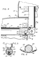
- Fig. 8 is a view similar to that of Fig. 7 with the hinge in an intermediate extended position;
- Fig. 9 is a view similar to that of Fig. 7 and 8 with a nose cone pivoted to the open position;
- Fig. 10 is a view similar to that of Fig. 9 with the nose cone pivoted from the open position to the intermediate position; and
- Fig. 11 is a view showing the hinge with the nose cone returned to the closed position.
- In Fig. 1, an
aircraft wing 10 is shown with an equipment nacelle or housing 11 suspended from the wing by astrut 12. The housing 11 has abody 13 and a nose orcover 14, typically of rounded or circular cross section and generally conical. The nose is shown in the open position in solid lines and in the closed position in phantom lines. Thebody 13 has aninner shoulder 15 which mates with arim 16 of thecover 14, as best seen in Fig. 4, to provide a smooth outer surface at the junction between the body and cover. - The nose cone is attached to the body by two hinges 17, which hinges are shown in greater detail in Figs. 2-6. Typically the hinges are affixed to the interior of the body and of the cover at the widest portions of the respective components. In this configuration, a worker standing on a ladder or a platform for working on equipment within the housing can raise the nose from the closed position to the open position with one hand, and can lower the nose to the closed position with one hand when the work is completed. This is a significant advantage with present day aircraft, where the wing is at a substantial height above the ground, and work is often carried out using a portable step ladder.
- In the preferred embodiment illustrated, a
sleeve 21 is attached to the body by mountingstraps 22 which typically are affixed to the body by rivets. Aslide arm 23 is similarly attached to thenose 14 by anothermounting strap 22. Atongue 24 of theslide arm 23 is pivotally mounted in aslot 25 of aslide block 26 by apin 27. - Starting with the hinges in the retracted position and the nose in the closed position of Fig. 2, the
nose cone 14 is pulled away from thebody 13 with theblock 26 sliding to the right in thesleeve 21 to an extended position, as shown in Fig. 3. This sliding motion is stopped by engagement of ashoulder 31 of the slide block with ashoulder 32 of the sleeve. Next the nose cone is pivoted, upward in the embodiment illustrated, from the position of Fig. 3 to the position of Fig. 4. Stops 33 on theslide arm 23 engagecorresponding notches 34 to provide a limit for the pivoting action. The nose cone may be maintained in the open position by a separate conventional strut, not shown. - A
cam 35 is mounted in theslot 25 of theslide block 26 by apin 36. Aspring 37 is positioned around thepin 36 and engages the cam and slide block for urging the cam clockwise as viewed in Figs. 2-4. - When in the condition of Fig. 4, a
shoulder 38 of the cam engages the outer end of thesleeve 21 and prevents inward sliding motion of the slide block, that is, motion to the left as viewed in Figs. 2-4. - When the worker wishes to close the housing, the nose is pivoted downward from the position of Fig. 4 to the position of Fig. 3. During this pivoting action, an
end 39 of thecam 35 is engaged by acam surface 40 on thetongue 24 and when thearm 23 reaches the aligned position of Fig. 3, thecam 39 has been pivoted counter clockwise, raising thecam shoulder 38 out of engagement with the end of thesleeve 21. Thestops 33 now engage withshoulder 42 of theslide block 26 to achieve the alignment of theslide arm 23 andslide block 26. - Next the nose cone is pushed into position on the body, with the
slide block 26 andslide arm 23 sliding into thesleeve 21, to the retracted position of Fig. 2. The nose cone may be maintained in the closed position by conventional latches, not shown. - An alternative and presently preferred embodiment of the sliding hinge is shown in Fig. 7-11, where components corresponding to those of Figs. 2-6 are identified by the same reference numbers.
- A
plunger 51 slides in apassage 52 in theslide block 26. A pin orrivet 53 is positioned transversely in thesleeve 21 and engages one end of theplunger 52 when the hinge is in the closed position as shown in Fig. 7. Thespring 37 has one end engaging thecam 35 and the other end engaging apin 54 in thehead 55 of the plunger. Thus the spring urges thecam 35 clockwise and urges theplunger 51 to the left, as viewed in the drawing figures. - A
second cam 57 is mounted in theslot 25 of theslide block 26 by apin 58. A detent mechanism is also provided in theslide block 26 in adetent passage 59, and includes aball 60, aspring 61, and aset screw 62 which closes the left end of thepassage 59. - The hinge mechanism is shown in the retracted position and the nose in the closed position in Fig. 7. In operation, the nose cone is pulled away from the body with the
block 26 sliding to the right in thesleeve 21 as shown in Fig. 8, with the sliding motion stopped by the engagement of theshoulder 31 with theshoulder 32. In the embodiment of Figs. 2-6, theshoulder 32 is formed integrally with thesleeve 21. In the embodiment of Figs. 7-11, theshoulder 32 is an extension of anend cap 32a fitted at the end of thesleeve 21. - Also, the
cam 57 is pivoted counter clockwise by thespring 59 andball 60 engaging thesurface 65 of thecam 57 bringing theend 66 of thecam 57 into locking engagement with theend 32a of thesleeve 21. This locks theslide arm 23 in the extended position of Fig. 8. - Next the nose cone is raised, moving the
arm 23 from the position of Fig. 8 to the position of Fig. 9. During this motion, thesurface 40 of thetongue 24 is moved away from theend 39 of thecam 35, and thespring 37 moves thecam 35 clockwise into locking engagement with theend 32a, as shown in Fig. 9. At the same time, anose 68 of thetongue 24 engages asurface 69 of thecam 57, rotating thecam 57 clockwise and over center past the detent ball and out of engagement with theend 32a, to the unlocking position shown in Fig. 9. - After completion of the work, the nose cone is lowered, moving the hinge toward the aligned position of Fig. 10. The
end 39 of thecam 35 is engaged by thesurface 40 of thetongue 24 moving thecam 35 counter clockwise and out of engagement with theend 32a. The hinge may now be slid to the retracted position of Fig. 11. - As the
slide block 26 moves to the left, the left end of theplunger 51 engages thepin 53 and moves the plunger in theblock 26 to the right to the dashed line position of Fig. 11. Thehead 55 of the plunger is in engagement with thecam 57, and the translating movement of the plunger causes the cam to pivot counter clockwise over center past the detent ball from the solid line position to the dashed line position. The hinge is now returned to the condition shown in Fig. 7. - Thus, by use of a sliding hinge according to the present invention, a cover or nose cone for a rounded body may be removed and positioned to one side providing clear access to the interior of the body, while maintaining a connection between the cover and body. The movement from the closed position to the open position may be accomplished by the worker with one hand, and any inadvertent inward movement of the slide components with the cover in the open position is blocked by the locking mechanism. However when desired, the cover is readily replaced in the closed position. This operation is achieved with the sliding hinges that can be placed at any location, particularly around the inner edges of the components, so that a minimum amount of interior space is required for the hinges.
Claims (12)
- A sliding hinge (17) for joining two members (11,14), comprising in combination:
a slide block (26) for sliding engagement with one of said members;
a slide arm (23) for attachment to the other of said members;
said block (26) and arm (23) including interengaging pivot means (27) for pivoting of said arm (23) relative to said block (26) between an extended position and an open position; characterised by
a first locking means (38) carried on one of said arm (23) and block (26) and engageable with said one member for limiting sliding of said block (26) when said block (26) and arm (23) are in said open position,
said block (26) and arm (23) including first interengaging cam means (35,40) for releasing said first locking means (38) when said arm (23) is pivoted to said extended position, said first locking means including:
a first cam (35) pivotally mounted on said one of said arm (23) and block (26) and having a first cam shoulder (38) engageable with said one member when said arm (23) is in said open position; and
first spring means (37) engaging said one of said arm (23) and block (26) and first cam (35) for urging said first cam shoulder (38) into engagement with said one member;
with said other of said arm (23) and block (26) having a first cam surface (40) engageable with said first cam (35) as said arm (23) pivots from said open position to said extended position for moving said first cam shoulder (38) out of engagement with said one member, said first cam (35) and first cam surface (40) forming said first interengaging cam means. - A sliding hinge as defined in claim 1 wherein said first locking means (38) limits sliding of said block (26) toward said one member, and including first stop means (31,32) for limiting sliding of said block (26) away from said one member.
- A sliding hinge as defined in claim 2 including second interengaging stop means (33,34) on said block (26) and arm (23) for defining said open position, and third interengaging stop means (33,42) on said block (26) and arm (23) for defining said extended position.
- A sliding hinge as defined in claim 1 wherein said block (26) is slideable relative to said one member between a retracted position and said extended position, and including
a second locking means (66) carried on one of said arm (23) and block (26) and engageable with said one member for limiting sliding of said block (26) when said block (26) is in said extended position,
said block (26) and arm (23) including second interengaging cam means (57,68) for releasing said second locking means (66) when said arm (23) is pivoted to said open position. - A sliding hinge as defined in claim 4 wherein said second locking means includes:
a second cam (57) pivotally mounted on said one of said arm (23) and block (26) and having a second cam shoulder (66) engageable with said one member when said block (26) is in said extended position; and
Second spring means (61) engaging said one of said arm (23) and block (26) and said second cam (57) for urging said second cam shoulder (66) into engagement with said one member;
with said other of said arm (23) and block (26) having a second cam surface (68) engageable with said second cam (57) as said arm (23) pivots from said extended position to said open position for moving said second cam shoulder (66) out of engagement with said one member, said second cam (57) and second cam surface (68) forming said second interengaging cam means. - A sliding hinge as defined in claim 5 wherein said second spring means (61) includes a detent (60) carried in said one of said arm (23) and block (26) in engagement with said second cam (57) to provide an over center action for said second cam (57) pivoting between locking and unlocking positions.
- A sliding hinge as defined in claim 6 including a plunger (51) slidingly mounted in said one of said arm (23) and block (26) for engaging said second cam (57) as said block (26) moves towards said retracted position, for pivoting said second cam (57) past said detent (60) from said unlocking position to said locking position.
- A sliding hinge as defined in claim 7 with said first spring means (37) engaging said plunger (51) for urging said plunger (51) away from said second cam (57), and
including a plunger stop (53) for limiting such movement of said plunger (51) away from said second cam (57). - A sliding hinge (17) for joining two members (11,14), comprising in combination:
a sleeve (21) for attachment to one of said members;
a slide block (26) for sliding in said sleeve (21);
a slide arm (23) for attachment to the other of said members;
said block (26) and arm (23) including interengaging pivot means (24,27) for pivoting of said arm (23) relative to said block (26) between an extended position and an open position; characterised by
first locking means (38) carried on one of said block (26) and arm (23) and engageable with said sleeve (21) for limiting sliding of said block (26) when said block (26) and arm (23) are in said open position,
said block (26) and arm (23) including first interengaging cam means (35,40) for releasing said first locking means (38) when said arm (23) is pivoted to said extended position, said first cam means including:
a first cam (35) mounted in a slot (25) in said one of said arm (23) and block (26), and
a first cam surface (40) carried on said other of said arm (23) and block (26) and moving through said slot (25); and
said first locking means including:
a first cam shoulder (38) on said first cam (35) engageable with said sleeve (21), and
first spring means (37) urging first cam shoulder (38) towards said sleeve (21),
with movement of said arm (23) from said open position to said extended position causing said first cam surface (40) to engage said first cam (35) and move said first cam shoulder (38) away from said sleeve (21). - A sliding hinge (17) for mounting a cover (14) on a generally rounded housing (11), comprising in combination:
a sleeve (21) for attachment at the interior of the housing (11);
a slide block (26) for sliding in said sleeve (21);
a slide arm (23) for attachment at the interior of the cover (14);
said block (26) and arm (23) including interengaging pivot means (24,27) for pivoting of said arm (23) relative to said block (26) between an extended position and an open position; characterised by
a first locking means (38) carried on one of said arm (23) and block (26) and engageable with said housing (11) for limiting sliding of said block (26) when said block (26) and arm (23) are in said open position,
said block (26) and arm (23) including first interengaging cam means (35,40) for releasing said first locking means (38) when said arm (23) is pivoted to said extended position, said first locking means including:
a first cam (35) pivotally mounted on said one of said arm (23) and block (26) and having a first cam shoulder (38) engageable with said sleeve (21) when said arm (23) is in said open position; and
first spring means (37) engaging said one of said arm (23) and block (26) and first cam (35) for urging said first cam shoulder (38) into engagement with said sleeve (21);
with said other of said arm (23) and block (26) having a first cam surface (40) engageable with said first cam (35) as said arm (23) pivots from said open position to said extended position for moving said first cam shoulder (38) out of engagement with said sleeve (21), said first cam (35) and first cam surface (40) forming said first interengaging cam means. - A sliding hinge as defined in claim 10 wherein said first locking means (38) limits sliding of said block (26) toward said housing (11) and including a first stop (31,32) for limiting sliding of said block (26) away from said housing (11).
- A sliding hinge as defined in claim 11 including second interengaging stop means (33,34) on said block (26) and arm (23) for defining said open position, and third interengaging stop means (33,42) on said block (26) and arm (23) for defining said extended position.
Applications Claiming Priority (2)
| Application Number | Priority Date | Filing Date | Title |
|---|---|---|---|
| US278495 | 1988-12-05 | ||
| US07/279,495 US4914783A (en) | 1988-12-05 | 1988-12-05 | Sliding hinge with locking |
Publications (2)
| Publication Number | Publication Date |
|---|---|
| EP0372675A1 EP0372675A1 (en) | 1990-06-13 |
| EP0372675B1 true EP0372675B1 (en) | 1993-08-04 |
Family
ID=23069241
Family Applications (1)
| Application Number | Title | Priority Date | Filing Date |
|---|---|---|---|
| EP89305064A Expired - Lifetime EP0372675B1 (en) | 1988-12-05 | 1989-05-18 | Sliding hinge with locking |
Country Status (5)
| Country | Link |
|---|---|
| US (1) | US4914783A (en) |
| EP (1) | EP0372675B1 (en) |
| BR (1) | BR8902320A (en) |
| DE (1) | DE68908116T2 (en) |
| ES (1) | ES2044112T3 (en) |
Families Citing this family (12)
| Publication number | Priority date | Publication date | Assignee | Title |
|---|---|---|---|---|
| FR2731049B1 (en) * | 1995-02-28 | 1997-05-09 | Aerospatiale | DEVICE FOR FIXING AN AIR INTAKE ON A REACTOR AND REACTOR COMPRISING SUCH A DEVICE |
| US7024728B2 (en) | 2002-02-11 | 2006-04-11 | Advantage Manufacturing Corp. | End cap for multi bar linkage hinge assembly |
| US6663045B2 (en) | 2002-02-11 | 2003-12-16 | The Boeing Company | Method and apparatus for actuating an aircraft nose portion |
| KR200317046Y1 (en) * | 2003-02-19 | 2003-06-25 | 이상규 | Hinge apparatus of ladder |
| ES2264625B1 (en) * | 2004-12-15 | 2007-12-01 | GAMESA INNOVATION & TECHNOLOGY, S.L. | REMOVAL PROCEDURE FROM THE COVER OF AN AIRBRUSHER. |
| US7137346B1 (en) | 2005-06-06 | 2006-11-21 | Rafael Francke | Locking hinge for unstayed mast deployment |
| JP5753849B2 (en) * | 2009-10-07 | 2015-07-22 | ランペ・ホールディングス・ベー・フェー | Portable ladder with stand-off device |
| WO2015013757A1 (en) * | 2013-07-29 | 2015-02-05 | Lift Link Housing Pty Ltd | Locking hinges |
| WO2018027683A1 (en) * | 2016-08-10 | 2018-02-15 | 张琬彬 | Quick disassembling and assembling wing of unmanned aerial vehicle |
| CN106240794B (en) * | 2016-08-24 | 2018-07-27 | 泰华伟业科技有限责任公司 | A kind of multi-rotor unmanned aerial vehicle horn folding device |
| US10982659B2 (en) * | 2016-09-21 | 2021-04-20 | Vestas Wind Systems A/S | Method for opening a cover portion of a wind turbine |
| WO2018213190A1 (en) * | 2017-05-13 | 2018-11-22 | Bruno Mombrinie | Stol aircraft |
Family Cites Families (7)
| Publication number | Priority date | Publication date | Assignee | Title |
|---|---|---|---|---|
| FR671654A (en) * | 1929-03-18 | 1929-12-16 | Cartier Sa | Invisible hinge system |
| US1898161A (en) * | 1930-06-02 | 1933-02-21 | Arnold Joseph Mathias | Hinge |
| US2630364A (en) * | 1949-11-25 | 1953-03-03 | Stromberg Carlson Co | Locking and release mechanism for multiposition units |
| FR1297940A (en) * | 1961-05-31 | 1962-07-06 | Folding chair with adjustable leg rest and backrest, especially for camping | |
| US3311945A (en) * | 1964-07-20 | 1967-04-04 | Honeywell Inc | Mechanical apparatus |
| FR2487899A1 (en) * | 1980-08-04 | 1982-02-05 | Rhodaniens Atel | Retractable edge-hung door for pigeon hole - pivots open through right angle then slides back using roller and slide in double guidage system |
| US4611945A (en) * | 1985-06-07 | 1986-09-16 | Diego Dennis F | Articulating joint for folding tubular sections |
-
1988
- 1988-12-05 US US07/279,495 patent/US4914783A/en not_active Expired - Lifetime
-
1989
- 1989-05-18 ES ES89305064T patent/ES2044112T3/en not_active Expired - Lifetime
- 1989-05-18 EP EP89305064A patent/EP0372675B1/en not_active Expired - Lifetime
- 1989-05-18 BR BR898902320A patent/BR8902320A/en not_active IP Right Cessation
- 1989-05-18 DE DE89305064T patent/DE68908116T2/en not_active Expired - Fee Related
Also Published As
| Publication number | Publication date |
|---|---|
| EP0372675A1 (en) | 1990-06-13 |
| DE68908116D1 (en) | 1993-09-09 |
| DE68908116T2 (en) | 1994-01-13 |
| BR8902320A (en) | 1990-11-13 |
| ES2044112T3 (en) | 1994-01-01 |
| US4914783A (en) | 1990-04-10 |
Similar Documents
| Publication | Publication Date | Title |
|---|---|---|
| US4914783A (en) | Sliding hinge with locking | |
| CA3059695C (en) | Drawer latch system | |
| EP3745915B1 (en) | Universal drawer slide | |
| CA1295646C (en) | Dual-purpose door system | |
| US5137327A (en) | Vehicle vent and escape hatch | |
| US4726092A (en) | Casement window hinge | |
| GB2180297A (en) | Door buffer | |
| EP3807167B1 (en) | Group lock box with recessed door to create a slim profile | |
| US3003495A (en) | Hinge construction | |
| US7001001B1 (en) | Cabinet | |
| US4451071A (en) | Adjustable strike | |
| US6948758B2 (en) | Hinge for a tonneau cover | |
| CN108005514B (en) | Control device for controlling the movement of a corner cabinet door of a corner cabinet | |
| US5074164A (en) | Angle positioning device | |
| US5248195A (en) | Separable bottom mounted drawer slide assembly | |
| US7506904B2 (en) | Door handle lock assembly with automatic lock and retract | |
| EP0040167B1 (en) | Adjustable retention latch assembly | |
| US20240252854A1 (en) | Saftey locking mechanism and method of using the same | |
| US3924885A (en) | Safety latch | |
| US3150659A (en) | Hinge construction | |
| JPH031572Y2 (en) | ||
| JP2511798Y2 (en) | Lock | |
| EP1036903B1 (en) | Closure for a wing, door or the like | |
| JPS63947Y2 (en) | ||
| AU771114B2 (en) | Door lock assembly |
Legal Events
| Date | Code | Title | Description |
|---|---|---|---|
| PUAI | Public reference made under article 153(3) epc to a published international application that has entered the european phase |
Free format text: ORIGINAL CODE: 0009012 |
|
| AK | Designated contracting states |
Kind code of ref document: A1 Designated state(s): DE ES FR GB IT NL |
|
| 17P | Request for examination filed |
Effective date: 19901130 |
|
| 17Q | First examination report despatched |
Effective date: 19920403 |
|
| GRAA | (expected) grant |
Free format text: ORIGINAL CODE: 0009210 |
|
| AK | Designated contracting states |
Kind code of ref document: B1 Designated state(s): DE ES FR GB IT NL |
|
| REF | Corresponds to: |
Ref document number: 68908116 Country of ref document: DE Date of ref document: 19930909 |
|
| ITF | It: translation for a ep patent filed | ||
| ET | Fr: translation filed | ||
| REG | Reference to a national code |
Ref country code: ES Ref legal event code: FG2A Ref document number: 2044112 Country of ref document: ES Kind code of ref document: T3 |
|
| PLBE | No opposition filed within time limit |
Free format text: ORIGINAL CODE: 0009261 |
|
| STAA | Information on the status of an ep patent application or granted ep patent |
Free format text: STATUS: NO OPPOSITION FILED WITHIN TIME LIMIT |
|
| 26N | No opposition filed | ||
| PGFP | Annual fee paid to national office [announced via postgrant information from national office to epo] |
Ref country code: FR Payment date: 20000822 Year of fee payment: 12 |
|
| PGFP | Annual fee paid to national office [announced via postgrant information from national office to epo] |
Ref country code: NL Payment date: 20000824 Year of fee payment: 12 |
|
| PGFP | Annual fee paid to national office [announced via postgrant information from national office to epo] |
Ref country code: GB Payment date: 20000825 Year of fee payment: 12 |
|
| PGFP | Annual fee paid to national office [announced via postgrant information from national office to epo] |
Ref country code: ES Payment date: 20000828 Year of fee payment: 12 Ref country code: DE Payment date: 20000828 Year of fee payment: 12 |
|
| PG25 | Lapsed in a contracting state [announced via postgrant information from national office to epo] |
Ref country code: GB Free format text: LAPSE BECAUSE OF NON-PAYMENT OF DUE FEES Effective date: 20010518 |
|
| PG25 | Lapsed in a contracting state [announced via postgrant information from national office to epo] |
Ref country code: ES Free format text: LAPSE BECAUSE OF NON-PAYMENT OF DUE FEES Effective date: 20010519 |
|
| PG25 | Lapsed in a contracting state [announced via postgrant information from national office to epo] |
Ref country code: NL Free format text: LAPSE BECAUSE OF NON-PAYMENT OF DUE FEES Effective date: 20011201 |
|
| GBPC | Gb: european patent ceased through non-payment of renewal fee |
Effective date: 20010518 |
|
| PG25 | Lapsed in a contracting state [announced via postgrant information from national office to epo] |
Ref country code: FR Free format text: LAPSE BECAUSE OF NON-PAYMENT OF DUE FEES Effective date: 20020131 |
|
| NLV4 | Nl: lapsed or anulled due to non-payment of the annual fee |
Effective date: 20011201 |
|
| PG25 | Lapsed in a contracting state [announced via postgrant information from national office to epo] |
Ref country code: DE Free format text: LAPSE BECAUSE OF NON-PAYMENT OF DUE FEES Effective date: 20020301 |
|
| REG | Reference to a national code |
Ref country code: ES Ref legal event code: FD2A Effective date: 20030303 |
|
| PG25 | Lapsed in a contracting state [announced via postgrant information from national office to epo] |
Ref country code: IT Free format text: LAPSE BECAUSE OF NON-PAYMENT OF DUE FEES;WARNING: LAPSES OF ITALIAN PATENTS WITH EFFECTIVE DATE BEFORE 2007 MAY HAVE OCCURRED AT ANY TIME BEFORE 2007. THE CORRECT EFFECTIVE DATE MAY BE DIFFERENT FROM THE ONE RECORDED. Effective date: 20050518 |