EP0372234B1 - Fluorescent lamp - Google Patents
Fluorescent lamp Download PDFInfo
- Publication number
- EP0372234B1 EP0372234B1 EP89120512A EP89120512A EP0372234B1 EP 0372234 B1 EP0372234 B1 EP 0372234B1 EP 89120512 A EP89120512 A EP 89120512A EP 89120512 A EP89120512 A EP 89120512A EP 0372234 B1 EP0372234 B1 EP 0372234B1
- Authority
- EP
- European Patent Office
- Prior art keywords
- compartments
- fluorescent lamp
- rectangular
- enclosure
- filament electrode
- Prior art date
- Legal status (The legal status is an assumption and is not a legal conclusion. Google has not performed a legal analysis and makes no representation as to the accuracy of the status listed.)
- Expired - Lifetime
Links
- 238000005192 partition Methods 0.000 claims description 16
- 239000003086 colorant Substances 0.000 claims description 10
- OAICVXFJPJFONN-UHFFFAOYSA-N Phosphorus Chemical compound [P] OAICVXFJPJFONN-UHFFFAOYSA-N 0.000 claims description 6
- 239000000919 ceramic Substances 0.000 description 7
- 239000011521 glass Substances 0.000 description 7
- XEEYBQQBJWHFJM-UHFFFAOYSA-N Iron Chemical compound [Fe] XEEYBQQBJWHFJM-UHFFFAOYSA-N 0.000 description 2
- 238000010276 construction Methods 0.000 description 2
- 238000010586 diagram Methods 0.000 description 2
- 230000008018 melting Effects 0.000 description 2
- 238000002844 melting Methods 0.000 description 2
- 239000011248 coating agent Substances 0.000 description 1
- 238000000576 coating method Methods 0.000 description 1
- 238000007599 discharging Methods 0.000 description 1
- 230000012447 hatching Effects 0.000 description 1
- 230000001939 inductive effect Effects 0.000 description 1
- 229910052742 iron Inorganic materials 0.000 description 1
- 230000014759 maintenance of location Effects 0.000 description 1
- 229910052753 mercury Inorganic materials 0.000 description 1
- 229910052751 metal Inorganic materials 0.000 description 1
- 239000002184 metal Substances 0.000 description 1
- 230000008520 organization Effects 0.000 description 1
- 229910052761 rare earth metal Inorganic materials 0.000 description 1
- 150000002910 rare earth metals Chemical class 0.000 description 1
- 238000002310 reflectometry Methods 0.000 description 1
Images



Classifications
-
- H—ELECTRICITY
- H01—ELECTRIC ELEMENTS
- H01J—ELECTRIC DISCHARGE TUBES OR DISCHARGE LAMPS
- H01J61/00—Gas-discharge or vapour-discharge lamps
- H01J61/92—Lamps with more than one main discharge path
Definitions
- the present invention relates to a fluorescent lamp, and particularly to a fluorescent lamp for use in a large sized color image display apparatus.
- FIG.6 is a front view of a conventional special type fluorescent lamp for use in a light emitting device for a large sized color image display apparatus.
- the special type fluorescent lamp has a hexagonal-shaped glass enclosure 20 comprising six triangular compartments 16a, 16b, 16c, 17a, 17b, 17c divided by six partitions, a filament cathode 19 common for all of the six triangular compartments disposed at the center part of the hexagonal enclosure, and six anode electrodes 18, 18, ... disposed near respective bottoms of the six triangular compartments.
- Respective triangular compartments have fluorescent films of three colors, for instance red, green, blue, red, green, blue.
- JP-A-62 188 160 describes an one pixel fluorescent lamp in which a common electrode is installed in an electrode chamber of an electrode chamber unit attached to the outer bottom part of a light source tube member. Discharge paths are formed by partition walls inside the light source tube member, and the whole planes of respective discharge paths are coated with phosphors. Positive electrodes arranged on an opening plane of the electrode chamber are inserted into the respective discharge paths.
- the purpose of the present invention is to provide a fluorescent lamp which is easy in arrangement on a color display panel, and has a high brightness and uniformity of brightness.
- the fluorescent lamp in accordance with the present invention comprises a rectangular gas-tight enclosure having a transparent or translucent face panel on the front face and a filament electrode container provided at the central parts on the rear wall, and the filament electrode container contains a common filament electrode therein.
- the rectangular enclosure and the filament electrode container together constitute an integral gas-tight enclosure.
- plural partitions are provided so as to divide the inside space of the rectangular enclosure into plural, such as six rectangle compartments, each of which is connected through respective connection holes to the space of the filament electrode container.
- the plural rectangle compartments form discharge spaces for lights of different colors.
- the filament electrode provided in the filament electrode container is disposed with its coil axis in a direction perpendicular to the lengthwise (hence vertical in the embodiment) partition walls disposed in the enclosure.
- Each compartment has an other electrode on the far end part from the connection hole.
- the inside walls of respective compartments have phosphor layers of different colors.
- a discharge gas comprising a rare gas, e.g. Ar, and Hg is confined in the enclosure. Therefore, gas discharge paths are constituted between the common filament electrode and the respective other electrodes at the far side of the compartments via respective connection holes.
- the rectangle enclosure coupled with the filament electrode container constitutes plural fluorescent lamps of different colors of light. Lighting or extinguishing of respective fluorescent lamps is controlled by potentials to be applied to the other electrodes, and the brightness of light is controlled by controlling currents or time periods (duty times) of the currents.
- the upper half portion of the rectangle enclosure having three compartments for three primary colors of light constitutes one pixel, and the lower half portion similarly constitutes the other one pixel. Therefore, the rectangle enclosure having six compartments constitutes two pixels.
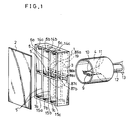
- FIG.1 is an exploded view of the fluorescent lamp embodying the present invention.
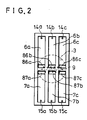
- FIG.2 is a front view of the fluorescent lamp of FIG.1.
- FIG.3 is a chromaticity diagram of light emitted by the fluorescent lamp of the embodiment (hatched region) and NTSC color reproduction range (in the chain line triangle region).
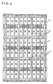
- FIG.4 is a drawing to show the arrangement of the fluorescent lamp of FIG.1 through FIG.3 in a color image display apparatus.
- FIG.5 is a drawing to show an arrangement of the fluorescent lamp of another example in a color image display apparatus.
- FIG.6 is a front view of the fluorescent lamp of the prior art.
- the fluorescent lamp of a preferred embodiment has a gas-tight rectangle enclosure 1 made of rectangle ceramic box of 34 mm height x 17 mm width x 10 mm depth size made of ceramics wherein the front face is a glass sheet 2 bonded gas-tightly on the front part of the ceramic enclosure 1 with low melting point glass.
- Rectangle enclosure 1 has several partition walls 5, 5, 5′ therein to divide the inside space of the enclosure 1 into six rectangle compartments. That is, two lengthwisely i. e. vertically disposed partitions 5, 5 and one crosswisely i. e. horizontally disposed partition 5' are provided like a lattice thereby producing six rectangle compartments 6a, 6b, 6c, 7a, 7b, 7c.
- each compartment is 14 mm length x 3.5 mm width x 3.5 mm depth.
- the ceramic rectangle enclosure 1 has six widthwise rectangle connection holes 86a, 86b, 86c, 87a, 87b, 87c on the rear wall in the compartment 6a, 6b, 6c, 7a, 7b, 7c, respectively, and a filament electrode container 4 having a filament electrode 9 therein is mounted in a circular recess 3 formed on the rear face of the rear wall and bonded gas-tightly to the rear wall with low temperature glass.
- the widthwisely rectangular connection holes 86a, 86b, 86c, 87a, 87b, 87c connect the inside space of the filament electrode container 4 and respective rectangle compartments 6a, 6b, 6c, 7a, 7b, 7c, respectively.
- the filament 9 is about 10 mm long, has a known emission oxide coating thereon, and is supported by a pair of inside lead wires 10, 10 which are provided on a glass stem 11. A pair of outer lead wires is connected to the inside lead wires 10, 10, respectively, and an evacuation tube 12 is provided on the stem 11.
- the filament 9 serves as a common cathode for all the six rectangle compartments 6a, 6b, 6c, 7a, 7b, 7c, and is disposed with its coil axis to be perpendicular to the planes of the lengthwise partitions 5, 5, and off-set rearward from the back face of rear wall 19 of the ceramic rectangle enclosure by 3 ⁇ 7mm.
- Respective compartments 6a, 6b, 6c, 7a, 7b, 7c comprise anode electrodes 14a, 14b 14c, 15a, 15b, 15c, all made of Ni-plated iron wire or the like high melting point metal, at their far end parts from the connection holes 86a, 86b, 86c, 87a, 87b, 87c, respectively.
- lead-wires to these anode electrodes are provided with gas-tight seal parts on the rear wall 19.
- six fluorescent lamps are constituted in the six compartments 6a, 6b, 6c, 7a, 7b, 7c, wherein gas discharge paths are formed between their anodes 14a, 14b, 14c, 15a, 15b, 15c and a common filament cathode 9 through the individual through-holes 86a, 86b, 86c, 87a, 87b, 87c, respectively.
- rare-earth phosphor layers for respective light colors are provided, for instance, a green emitting phosphor layer in the compartments 6a, 7a, a red light emitting phosphor layer in the compartments 6b and 7b, and a blue light emitting phosphor layers in the compartments 6c and 7c.
- a rare gas e. g. Ar of 1300 ⁇ 2000 Pa (10 ⁇ 15 Torr)., especially of about 1730 Pa (13 Torr). is confined together with a necessary amount of Hg in the rectangle enclosure 1.
- FIG.4 is a front view showing an arrangement of an assembly of the fluorescent lamps shown in FIG.1 and FIG.2, wherein straight lines show outside faces of the outside walls 1′, 1′, of the rectangle enclosure 1, and double parallel vertical lines show vertical partition walls 5, 5 in the rectangle enclosure 1.
- the fluorescent lamp in accordance with the present invention has a rectangle outside shape, wherein each compartment as discharge space is also rectangle. Therefore, the space factor of the discharge space per area of the compartment is high. Furthermore, since the outside shape of the rectangle enclosure 1 is rectangle, its arrangement on the large-sized display panel is very simple as shown in FIG.4. That is, the enclosures can only be disposed in vertical and horizontal rows. Since the common filament electrode 9 is disposed with its coil axis perpendicular to the plane of the vertical partition walls, in other words, perpendicular to the discharge paths in respective compartments 6a, 6b, 6c, 7a, 7b, 7c, with an off-set distance from the back face of the rear wall 19, the supply of thermal electrons to respective discharge spaces is uniform. Therefore, discharge maintain voltages for all discharge paths are uniform, and hence there is substantially no irregularity of brightness on the screen. Since the rectangle enclosure 1 is made of a ceramic box, it is easily produced with a highly accurate size and shape.
- a voltage above a discharge start voltage is applied from an auxiliary discharge current source to respective anodes 14a, 14b, 14c, 15a, 15b, 15c and the common cathode, thereby to start discharging with auxiliary discharge currents which are limited to small currents of, e.g. about 10 »A.
- auxiliary discharge currents which are limited to small currents of, e.g. about 10 »A.
- large discharge currents e.g. about 10 mA are fed to the respective anodes, controlling the duty times thereof based on picture signals.
- the ratio of brightness to input electric power was improved to 1.3 times the ratio of the conventional fluorescent lamp shown in FIG.6.
- the number of fluorescent lamps per area can be increased to 1.3 times the number using the conventional fluorescent lamp shown in FIG.6.
- Use of the ceramic box in place of conventional glass box as the rear part of the rectangle fluorescent lamp enclosure of this example improves reflectivity of emitted light, and improves the brightness in comparison with the use of an all glass fluorescent lamp enclosure. Furthermore, because of achievement of a uniform discharge maintain voltage of the respective element discharge paths in each fluorescent lamp, substantially no brightness fluctuation or irregularity was observed.
- 3n ( n is 1, 2, 3 ...) (in this example 6) rectangular compartments are formed in widthwise direction thereby to provide 2n (in this example 4) pixels (i.e. n upper pixels and n lower pixels) in one rectangle fluorescent lamp having a widthwisely long filament electrode, as shown in FIG.5.
Landscapes
- Vessels And Coating Films For Discharge Lamps (AREA)
Description
- The present invention relates to a fluorescent lamp, and particularly to a fluorescent lamp for use in a large sized color image display apparatus.
- FIG.6 is a front view of a conventional special type fluorescent lamp for use in a light emitting device for a large sized color image display apparatus. The special type fluorescent lamp has a hexagonal-
shaped glass enclosure 20 comprising sixtriangular compartments filament cathode 19 common for all of the six triangular compartments disposed at the center part of the hexagonal enclosure, and sixanode electrodes - JP-A-62 188 160 describes an one pixel fluorescent lamp in which a common electrode is installed in an electrode chamber of an electrode chamber unit attached to the outer bottom part of a light source tube member. Discharge paths are formed by partition walls inside the light source tube member, and the whole planes of respective discharge paths are coated with phosphors. Positive electrodes arranged on an opening plane of the electrode chamber are inserted into the respective discharge paths.
- The purpose of the present invention is to provide a fluorescent lamp which is easy in arrangement on a color display panel, and has a high brightness and uniformity of brightness.
- This object is achieved in a fluorescent lamp according to the features of claim 1.
- The fluorescent lamp in accordance with the present invention comprises a rectangular gas-tight enclosure having a transparent or translucent face panel on the front face and a filament electrode container provided at the central parts on the rear wall, and the filament electrode container contains a common filament electrode therein. The rectangular enclosure and the filament electrode container together constitute an integral gas-tight enclosure. In the rectangular enclosure, plural partitions are provided so as to divide the inside space of the rectangular enclosure into plural, such as six rectangle compartments, each of which is connected through respective connection holes to the space of the filament electrode container. The plural rectangle compartments form discharge spaces for lights of different colors. The filament electrode provided in the filament electrode container is disposed with its coil axis in a direction perpendicular to the lengthwise (hence vertical in the embodiment) partition walls disposed in the enclosure. Each compartment has an other electrode on the far end part from the connection hole. The inside walls of respective compartments have phosphor layers of different colors. A discharge gas comprising a rare gas, e.g. Ar, and Hg is confined in the enclosure. Therefore, gas discharge paths are constituted between the common filament electrode and the respective other electrodes at the far side of the compartments via respective connection holes. Thus, the rectangle enclosure coupled with the filament electrode container constitutes plural fluorescent lamps of different colors of light. Lighting or extinguishing of respective fluorescent lamps is controlled by potentials to be applied to the other electrodes, and the brightness of light is controlled by controlling currents or time periods (duty times) of the currents. The upper half portion of the rectangle enclosure having three compartments for three primary colors of light constitutes one pixel, and the lower half portion similarly constitutes the other one pixel. Therefore, the rectangle enclosure having six compartments constitutes two pixels.
- The invention, both as to organization and content, will be better understood and appreciated, along with other objects and features thereof, from the following detailed description taken in conjunction with the drawings.
- FIG.1 is an exploded view of the fluorescent lamp embodying the present invention.
- FIG.2 is a front view of the fluorescent lamp of FIG.1.
- FIG.3 is a chromaticity diagram of light emitted by the fluorescent lamp of the embodiment (hatched region) and NTSC color reproduction range (in the chain line triangle region).
- FIG.4 is a drawing to show the arrangement of the fluorescent lamp of FIG.1 through FIG.3 in a color image display apparatus.
- FIG.5 is a drawing to show an arrangement of the fluorescent lamp of another example in a color image display apparatus.
- FIG.6 is a front view of the fluorescent lamp of the prior art.
- It will be recognized that some or all of the Figures are schematic representations for purposes of illustration and do not necessarily depict the actual relative sizes or locations of the elements shown.
- As shown in FIG.1, the fluorescent lamp of a preferred embodiment has a gas-tight rectangle enclosure 1 made of rectangle ceramic box of 34 mm height x 17 mm width x 10 mm depth size made of ceramics wherein the front face is a
glass sheet 2 bonded gas-tightly on the front part of the ceramic enclosure 1 with low melting point glass. Rectangle enclosure 1 hasseveral partition walls partitions rectangle compartments rectangle connection holes compartment filament electrode container 4 having afilament electrode 9 therein is mounted in acircular recess 3 formed on the rear face of the rear wall and bonded gas-tightly to the rear wall with low temperature glass. The widthwiselyrectangular connection holes filament electrode container 4 andrespective rectangle compartments filament 9 is about 10 mm long, has a known emission oxide coating thereon, and is supported by a pair ofinside lead wires glass stem 11. A pair of outer lead wires is connected to theinside lead wires evacuation tube 12 is provided on thestem 11. Thefilament 9 serves as a common cathode for all the sixrectangle compartments lengthwise partitions rear wall 19 of the ceramic rectangle enclosure by 3―7mm.Respective compartments anode electrodes 14b connection holes rear wall 19. - By the above-mentioned construction, six fluorescent lamps are constituted in the six
compartments anodes common filament cathode 9 through the individual through-holes - On the inside faces of the
rear wall 19 of the respective compartments, rare-earth phosphor layers for respective light colors are provided, for instance, a green emitting phosphor layer in thecompartments compartments compartments - As discharge gas, a rare gas, e. g. Ar of 1300―2000 Pa (10―15 Torr)., especially of about 1730 Pa (13 Torr). is confined together with a necessary amount of Hg in the rectangle enclosure 1.
- In this way, the
compartments compartments vertical partition walls - The fluorescent lamp in accordance with the present invention has a rectangle outside shape, wherein each compartment as discharge space is also rectangle. Therefore, the space factor of the discharge space per area of the compartment is high. Furthermore, since the outside shape of the rectangle enclosure 1 is rectangle, its arrangement on the large-sized display panel is very simple as shown in FIG.4. That is, the enclosures can only be disposed in vertical and horizontal rows. Since the
common filament electrode 9 is disposed with its coil axis perpendicular to the plane of the vertical partition walls, in other words, perpendicular to the discharge paths inrespective compartments rear wall 19, the supply of thermal electrons to respective discharge spaces is uniform. Therefore, discharge maintain voltages for all discharge paths are uniform, and hence there is substantially no irregularity of brightness on the screen. Since the rectangle enclosure 1 is made of a ceramic box, it is easily produced with a highly accurate size and shape. - In order to display a picture with the fluorescent lamp of the embodiment, first a voltage above a discharge start voltage is applied from an auxiliary discharge current source to
respective anodes - When the brightness of the fluorescent lamp in accordance with the present invention is compared with the fluorescent lamp of the prior art shown in FIG.6, the ratio of brightness to input electric power was improved to 1.3 times the ratio of the conventional fluorescent lamp shown in FIG.6. Furthermore, by arranging the fluorescent lamps in accordance with the present invention as shown in FIG.4, the number of fluorescent lamps per area can be increased to 1.3 times the number using the conventional fluorescent lamp shown in FIG.6. Use of the ceramic box in place of conventional glass box as the rear part of the rectangle fluorescent lamp enclosure of this example improves reflectivity of emitted light, and improves the brightness in comparison with the use of an all glass fluorescent lamp enclosure. Furthermore, because of achievement of a uniform discharge maintain voltage of the respective element discharge paths in each fluorescent lamp, substantially no brightness fluctuation or irregularity was observed.
- In a still other embodiment of FIG.5, 3n ( n is 1, 2, 3 ...) (in this example 6) rectangular compartments are formed in widthwise direction thereby to provide 2n (in this example 4) pixels (i.e. n upper pixels and n lower pixels) in one rectangle fluorescent lamp having a widthwisely long filament electrode, as shown in FIG.5.
- Although the invention has been described in its preferred form with a certain degree of particularity, it is understood that the present disclosure of the preferred form can been changed in the details of construction and the combination and arrangement of parts may be resorted to without departing from the scope of the claims.
Claims (3)
- A fluorescent lamp comprising:
a rectangular gas-tight enclosure (1) having a transparent or translucent face panel (2) on the front face,
3n-1 (n is 1, 2, 3 ...) lengthwise partitions (5, 5) and a widthwise partition (5') which are provided in said rectangular enclosure (1) to divide its inside space into 3n (n is 1, 2, 3, ...) rectangular compartments in an upper row and in a lower row,
a filament electrode container (4) provided at the central part on the rear wall (19) of said rectangular gas-tight enclosure (1) in a manner to be connected to the inside space of said rectangular enclosure (1) through 3n (n is 1, 2, 3 ...) connection holes formed in said plural rectangular compartments at the central part of said rear wall (19), respectively,
a common filament electrode (9) provided in said filament electrode cointainer (4) with its axis substantially perpendicular to the plane of said lengthwise partitions in a manner to substantially extend to face all the connection holes,
plural other electrodes provided in respective ones of said compartments at their far end regions from said connection holes,
phosphor layers for emission of light of three different colors (R, G, b) provided on each of the first-side pixel regions which are formed by the 3n compartments (6a, 6b, 6c) on one side of said widthwise partition (5') and of the second-side pixel regions which are formed by the 3n compartments (7a, 7b, 7c) on the other side of said widthwise partition (5'), and
a discharge gas comprising at least a rare gas and Hg, whereby
discharge paths are formed in respective rectangular compartments between said common filament electrode and respective ones of other electrodes, to provide 2n pixels. - A fluorescent lamp in accordance with claim 1, wherein n is 1.
- A fluorescent lamp in accordance with claim 1 or 2, wherein
said connection holes are made on a recessed area (3) on the rear face of said rear wall (19), and
said filament electrode container (4) is mounted in and fixed to said recess.
Applications Claiming Priority (2)
| Application Number | Priority Date | Filing Date | Title |
|---|---|---|---|
| JP282960/88 | 1988-11-09 | ||
| JP63282960A JP2741877B2 (en) | 1988-11-09 | 1988-11-09 | Fluorescent lamp |
Publications (2)
| Publication Number | Publication Date |
|---|---|
| EP0372234A1 EP0372234A1 (en) | 1990-06-13 |
| EP0372234B1 true EP0372234B1 (en) | 1994-07-06 |
Family
ID=17659357
Family Applications (1)
| Application Number | Title | Priority Date | Filing Date |
|---|---|---|---|
| EP89120512A Expired - Lifetime EP0372234B1 (en) | 1988-11-09 | 1989-11-06 | Fluorescent lamp |
Country Status (3)
| Country | Link |
|---|---|
| EP (1) | EP0372234B1 (en) |
| JP (1) | JP2741877B2 (en) |
| DE (1) | DE68916621T2 (en) |
Families Citing this family (2)
| Publication number | Priority date | Publication date | Assignee | Title |
|---|---|---|---|---|
| JP3532578B2 (en) * | 1991-05-31 | 2004-05-31 | 三菱電機株式会社 | Discharge lamp and image display device using the same |
| CA2127850C (en) * | 1993-07-19 | 1999-03-16 | Matsushita Electric Industrial Co., Ltd. | Luminescent panel for color video display and its driving system, and a color video display apparatus utilizing the same |
Family Cites Families (2)
| Publication number | Priority date | Publication date | Assignee | Title |
|---|---|---|---|---|
| JPS60123179A (en) * | 1983-12-07 | 1985-07-01 | Mitsubishi Electric Corp | Color picture display device |
| KR900008228B1 (en) * | 1986-10-31 | 1990-11-06 | 가부시기가이샤 도시바 | Fluorescent lamp emitting the multi-colored beam |
-
1988
- 1988-11-09 JP JP63282960A patent/JP2741877B2/en not_active Expired - Fee Related
-
1989
- 1989-11-06 DE DE1989616621 patent/DE68916621T2/en not_active Expired - Fee Related
- 1989-11-06 EP EP89120512A patent/EP0372234B1/en not_active Expired - Lifetime
Non-Patent Citations (1)
| Title |
|---|
| PATENT ABSTRACTS OF JAPAN, vol. 12, no. 30 (E-578)(2877), 28 January 1988; & JP-A-62 188 160 * |
Also Published As
| Publication number | Publication date |
|---|---|
| DE68916621D1 (en) | 1994-08-11 |
| JP2741877B2 (en) | 1998-04-22 |
| EP0372234A1 (en) | 1990-06-13 |
| DE68916621T2 (en) | 1995-02-16 |
| JPH02129847A (en) | 1990-05-17 |
Similar Documents
| Publication | Publication Date | Title |
|---|---|---|
| US3882342A (en) | Gas discharge display panel for color picture reproduction | |
| US4633134A (en) | Color fluorescent display device having anode conductors in zig-zag pattern | |
| EP0372234A1 (en) | Fluorescent lamp | |
| US3899636A (en) | High brightness gas discharge display device | |
| CA2127850C (en) | Luminescent panel for color video display and its driving system, and a color video display apparatus utilizing the same | |
| JP2005347260A (en) | Plasma display panel | |
| US4220892A (en) | Phosphor screen for modular flat panel display device | |
| JPH0346748A (en) | Fluoresocent lamp | |
| US5608419A (en) | Gas flat display tube with anode gates | |
| JPH03269933A (en) | Gas discharge panel | |
| JPH0794144A (en) | Planar light color variable light source | |
| JP3184543B2 (en) | Character display device | |
| KR0142023B1 (en) | Color plasma display device | |
| JP2751192B2 (en) | Fluorescent display tube | |
| JPS6313186B2 (en) | ||
| JPH0454339B2 (en) | ||
| JPH0713173Y2 (en) | Fluorescent tube | |
| JPH11111232A (en) | Fluorescent lamp for display | |
| JPH0542108B2 (en) | ||
| JPH0321916B2 (en) | ||
| JPH0622920Y2 (en) | Fluorescent display device | |
| JPH02165554A (en) | Flat light-emission discharge lamp | |
| JP2005032721A (en) | Self-luminous color display device and driving method thereof | |
| JPH11224623A (en) | Fluorescent illumination tube | |
| JPS62119837A (en) | Fluorescent emitting tube |
Legal Events
| Date | Code | Title | Description |
|---|---|---|---|
| PUAI | Public reference made under article 153(3) epc to a published international application that has entered the european phase |
Free format text: ORIGINAL CODE: 0009012 |
|
| 17P | Request for examination filed |
Effective date: 19891106 |
|
| AK | Designated contracting states |
Kind code of ref document: A1 Designated state(s): DE GB |
|
| 17Q | First examination report despatched |
Effective date: 19930105 |
|
| GRAA | (expected) grant |
Free format text: ORIGINAL CODE: 0009210 |
|
| AK | Designated contracting states |
Kind code of ref document: B1 Designated state(s): DE GB |
|
| REF | Corresponds to: |
Ref document number: 68916621 Country of ref document: DE Date of ref document: 19940811 |
|
| PLBE | No opposition filed within time limit |
Free format text: ORIGINAL CODE: 0009261 |
|
| STAA | Information on the status of an ep patent application or granted ep patent |
Free format text: STATUS: NO OPPOSITION FILED WITHIN TIME LIMIT |
|
| 26N | No opposition filed | ||
| REG | Reference to a national code |
Ref country code: GB Ref legal event code: IF02 |
|
| REG | Reference to a national code |
Ref country code: GB Ref legal event code: 732E |
|
| PGFP | Annual fee paid to national office [announced via postgrant information from national office to epo] |
Ref country code: GB Payment date: 20041104 Year of fee payment: 16 Ref country code: DE Payment date: 20041104 Year of fee payment: 16 |
|
| PG25 | Lapsed in a contracting state [announced via postgrant information from national office to epo] |
Ref country code: GB Free format text: LAPSE BECAUSE OF NON-PAYMENT OF DUE FEES Effective date: 20051106 |
|
| PG25 | Lapsed in a contracting state [announced via postgrant information from national office to epo] |
Ref country code: DE Free format text: LAPSE BECAUSE OF NON-PAYMENT OF DUE FEES Effective date: 20060601 |
|
| GBPC | Gb: european patent ceased through non-payment of renewal fee |
Effective date: 20051106 |