EP0370977B1 - A boat-propeller unit - Google Patents
A boat-propeller unit Download PDFInfo
- Publication number
- EP0370977B1 EP0370977B1 EP89850359A EP89850359A EP0370977B1 EP 0370977 B1 EP0370977 B1 EP 0370977B1 EP 89850359 A EP89850359 A EP 89850359A EP 89850359 A EP89850359 A EP 89850359A EP 0370977 B1 EP0370977 B1 EP 0370977B1
- Authority
- EP
- European Patent Office
- Prior art keywords
- propeller
- sensor
- leg
- boat
- carrier
- Prior art date
- Legal status (The legal status is an assumption and is not a legal conclusion. Google has not performed a legal analysis and makes no representation as to the accuracy of the status listed.)
- Expired - Lifetime
Links
Images

Classifications
-
- B—PERFORMING OPERATIONS; TRANSPORTING
- B63—SHIPS OR OTHER WATERBORNE VESSELS; RELATED EQUIPMENT
- B63H—MARINE PROPULSION OR STEERING
- B63H20/00—Outboard propulsion units, e.g. outboard motors or Z-drives; Arrangements thereof on vessels
- B63H20/08—Means enabling movement of the position of the propulsion element, e.g. for trim, tilt or steering; Control of trim or tilt
- B63H20/10—Means enabling trim or tilt, or lifting of the propulsion element when an obstruction is hit; Control of trim or tilt
Definitions
- the present invention relates to a boat-propeller unit comprising a carrier which can be mounted rigidly to the transom of a boat, and a propeller-leg which is carried by the carrier and which can be tilted around a horizontal shaft for adjustment of the propeller-leg to selected angles relative to the carrier and which can be swung around a steering axis which extends in a vertical plane, and wherein means are provided for sending a signal which corresponds to the tilt-angle of the propeller-leg to an angle indicating instrument.
- Boat-propeller units of this kind such as inboard-outboard drives, for instance, can be "trimmed" in different positions relative to the carrier, i.e. relative to the boat-transom, so as to adjust the position of the propeller-leg to the attitude of the boat in the water.
- Modern propeller-units of this kind are provided with an electric sensor which is coupled to a position indicator mounted on the instrument panel of the boat and operative to indicate the prevailing trim and tilt angle.
- the object of the present invention is to provide a further development of this latter type of sensor arrangement which will obviate the need for mechanical connection between the tilt-angle sensing components on that part of the propeller unit mounted on the transom and on the propeller-leg, so as to provide a construction which is not affected by wear and which is particularly insensitive to the ambient environment.
- a boat-propeller unit of the aforesaid kind which incorporates a signal-producing device which includes a sensor of known kind capable of producing an output signal in dependence on the distance to a surface of an object, and also an object which coacts with the sensor; and in which arrangement the sensor and said surface of said object are so arranged in relation to one another on the carrier and on the propeller-leg respectively that the distance therebetween changes in response to changes in the tilt-angle of the propeller-leg, with subsequent changes in the output signal from the sensor.
- a signal-producing device which includes a sensor of known kind capable of producing an output signal in dependence on the distance to a surface of an object, and also an object which coacts with the sensor; and in which arrangement the sensor and said surface of said object are so arranged in relation to one another on the carrier and on the propeller-leg respectively that the distance therebetween changes in response to changes in the tilt-angle of the propeller-leg, with subsequent changes in the output signal from the sensor.
- Such a sensor can be placed advantageously in the bore provided in the steering shaft, this bore being used previously to accommodate the shaft of the rotary potentiometer.
- the sensor used can be of any known kind capable of indicating the presence of a magnetizable object and also capable of producing, within a defined area, a signal which will vary with the distance to the object.
- the aforementioned "rack" mounted on the helmet can then be replaced with a strip of magnetizable material which is curved in an arc which is excentric relative to the tilt-axle of the propeller-leg. The distance between the outer end of the sensor and the surface of said strip will thus vary in dependence on the angle defined between the propeller-leg and its carrier (the shield).
- the invention provides a completely contactless angle-sensing arrangement which can be used with a known propeller unit with only negligible modification thereto.
- Figure 1 is a side-view of a known inboard-outboard drive
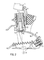
- Figure 2 is a longitudinal section through the steering shaft and helmet of a drive constructed in accordance with the invention.
- the reference 1 identifies the transom of a boat, said transom having provided therein an aperture 2 in which there is mounted a boat-propeller unit of the kind normally referred to as an inboard-outboard drive and which is shown generally at 3.
- the drive includes a carrier or shield 4, which is mounted on the transom, and a propeller-leg 5 which is suspended from the shield 4.
- a steering shaft 6 having a fork 7 is journalled to the shield and is connected to a steering arm 8 which is intended to be connected to the steering lever of the boat or vessel.
- the outer ends of the legs of the fork 7 have provided thereon journal pins 9 which pivotally mount a helmet 10.
- the helmet 10 covers the drive-shaft couplings and is connected to the propeller-leg 5 for the purpose of transferring the torque generated by the steering-shaft to the propeller-leg.
- the surface 11 of the helmet is curved in a plane of symmetry around an arc whose centre lies on the centre axis of the tilt-axle 9.
- the angle at which the propeller-leg 5 is tilted in relation to the transom can be adjusted with the aid of piston-cylinder devices (not shown) so-called trimming and tilting piston-cylinder devices, positioned between the shield 4 and the propeller-leg 5, so as to be able to adapt the positional setting of the propeller-leg to the prevailing attitude of the boat in the water, the depth of water through which the boat moves, etc.
- FIG 2 is a longitudinal, sectional view of a steering shaft 6 and a helmet 10, which form part of a drive of the same principle construction as the drive illustrated in Figure 1, but modified with respect to the configuration of the helmet 10.
- the curvature of the helmet 10 in Figure 1 in the plane of symmetry i.e. the arc whose centre lies on the centre of the tilt- shaft 9, is shown in chain in Figure 2.
- the helmet configuration of the Figure 2 embodiment is different to that of the Figure 1 embodiment, insomuch as the helmet is curved in the plane of symmetry about an arc which is excentric in relation to the arc of curvature of the helmet shown in Figure 1.
- the distance between the surface 11 of the helmet and the overlying parts of the carrier 4, e.g. the lower end of the steering shaft 6, will change with changes in the angle subtended by the propeller-leg 5 and the carrier or shield 4.
- the curvature is such that the distance between the surface 11 of the helmet is smallest when the propeller-leg 5 is at its lower maximum, and greatest when the propeller-leg is raised to its maximum, although the opposite may equally as well be the case.
- the distance differential is in the order of 5 mm.
- the steering shaft 6 is configured with a central, through-passing bore 12, which accommodates a sensor 13 and a protective cover 14.
- the sensor 13 is of known kind and functions to produce an electric signal which is contingent on the distance from the outer end 15 of the sensor to an object located in front of said outer end.
- the sensor may be an inductive sensor, for instance a sensor of the kind sold under the trade designation Telemecanique XSP HO 8362, which indicates the presence of a magnetizable object and the distance thereto.
- the sensor 13 will produce a signal which is contingent on the angular setting of the propeller-leg in relation to the boat and which can be fed into an instrument from which said angular setting can be read-off immediately.
- This function can also be achieved in a very simple fashion, even when the actual helmet contains no magnetizable material. In this latter case, it suffices to bond to the centre part of the helmet a magnet tape of the same kind as standard audio-video tape.
- the inductive sensor can be replaced with an ultrasonic or infralight sensor operative to measure the distance to an object which moves in response to changes in the tilt-angle of the propeller-leg.
- an optical sensor is more sensitive positionwise, due to the fact that its performance can be influenced by dirt and water-splashes, for instance.
- an arcuate helmet which curves concentrically with the tilt-axis can be retained and a ridge having the longitudinal section shown in Figure 2 can be built-up on the helmet.
Landscapes
- Chemical & Material Sciences (AREA)
- Engineering & Computer Science (AREA)
- Combustion & Propulsion (AREA)
- Mechanical Engineering (AREA)
- Ocean & Marine Engineering (AREA)
- Measurement Of Length, Angles, Or The Like Using Electric Or Magnetic Means (AREA)
- Vehicle Body Suspensions (AREA)
- Surgical Instruments (AREA)
- Extrusion Moulding Of Plastics Or The Like (AREA)
- Length Measuring Devices With Unspecified Measuring Means (AREA)
Abstract
Description
- The present invention relates to a boat-propeller unit comprising a carrier which can be mounted rigidly to the transom of a boat, and a propeller-leg which is carried by the carrier and which can be tilted around a horizontal shaft for adjustment of the propeller-leg to selected angles relative to the carrier and which can be swung around a steering axis which extends in a vertical plane, and wherein means are provided for sending a signal which corresponds to the tilt-angle of the propeller-leg to an angle indicating instrument.
- Boat-propeller units of this kind, such as inboard-outboard drives, for instance, can be "trimmed" in different positions relative to the carrier, i.e. relative to the boat-transom, so as to adjust the position of the propeller-leg to the attitude of the boat in the water. Modern propeller-units of this kind are provided with an electric sensor which is coupled to a position indicator mounted on the instrument panel of the boat and operative to indicate the prevailing trim and tilt angle.
- Of the different kinds of sensor arrangements known to the art mention can be made here to the kind in which the sensor is coordinated with the tilting axle, and also to the kind with which a sensor is intended to coact with the steering shaft and a position indicator is mounted on the propeller-leg. SE 449 080 teaches a sensor arrangement of this latter kind, in which the sensor has the form of a rotary potentiometer which has mounted on the shaft thereof a toothed wheel or pinion which meshes with a "rack" mounted on a helmet which forms a connecting element between the steering shaft and the propeller-leg. The advantage with this solution over the solution first mentioned is that all electrical equipment can be placed so as to be protected against water-splashes, i.e. can be placed on the inward side of the carrier or the shield which forms the propeller-suspension on the boat-transom and through which the steering shaft extends.
- The object of the present invention is to provide a further development of this latter type of sensor arrangement which will obviate the need for mechanical connection between the tilt-angle sensing components on that part of the propeller unit mounted on the transom and on the propeller-leg, so as to provide a construction which is not affected by wear and which is particularly insensitive to the ambient environment.
- This is achieved in accordance with the invention with a boat-propeller unit of the aforesaid kind which incorporates a signal-producing device which includes a sensor of known kind capable of producing an output signal in dependence on the distance to a surface of an object, and also an object which coacts with the sensor; and in which arrangement the sensor and said surface of said object are so arranged in relation to one another on the carrier and on the propeller-leg respectively that the distance therebetween changes in response to changes in the tilt-angle of the propeller-leg, with subsequent changes in the output signal from the sensor.
- Such a sensor can be placed advantageously in the bore provided in the steering shaft, this bore being used previously to accommodate the shaft of the rotary potentiometer. The sensor used can be of any known kind capable of indicating the presence of a magnetizable object and also capable of producing, within a defined area, a signal which will vary with the distance to the object. The aforementioned "rack" mounted on the helmet can then be replaced with a strip of magnetizable material which is curved in an arc which is excentric relative to the tilt-axle of the propeller-leg. The distance between the outer end of the sensor and the surface of said strip will thus vary in dependence on the angle defined between the propeller-leg and its carrier (the shield).
- The invention provides a completely contactless angle-sensing arrangement which can be used with a known propeller unit with only negligible modification thereto.
- The invention will now be described in more detail with reference to an exemplifying embodiment thereof illustrated in the accompanying drawings, of which Figure 1 is a side-view of a known inboard-outboard drive, and Figure 2 is a longitudinal section through the steering shaft and helmet of a drive constructed in accordance with the invention.
- In Figure 1 the reference 1 identifies the transom of a boat, said transom having provided therein an aperture 2 in which there is mounted a boat-propeller unit of the kind normally referred to as an inboard-outboard drive and which is shown generally at 3. The drive includes a carrier or shield 4, which is mounted on the transom, and a propeller-
leg 5 which is suspended from the shield 4. Asteering shaft 6 having afork 7 is journalled to the shield and is connected to a steering arm 8 which is intended to be connected to the steering lever of the boat or vessel. The outer ends of the legs of thefork 7 have provided thereon journal pins 9 which pivotally mount ahelmet 10. Thehelmet 10 covers the drive-shaft couplings and is connected to the propeller-leg 5 for the purpose of transferring the torque generated by the steering-shaft to the propeller-leg. In the case of the illustrated embodiment, thesurface 11 of the helmet is curved in a plane of symmetry around an arc whose centre lies on the centre axis of the tilt-axle 9. The angle at which the propeller-leg 5 is tilted in relation to the transom can be adjusted with the aid of piston-cylinder devices (not shown) so-called trimming and tilting piston-cylinder devices, positioned between the shield 4 and the propeller-leg 5, so as to be able to adapt the positional setting of the propeller-leg to the prevailing attitude of the boat in the water, the depth of water through which the boat moves, etc. - Figure 2 is a longitudinal, sectional view of a
steering shaft 6 and ahelmet 10, which form part of a drive of the same principle construction as the drive illustrated in Figure 1, but modified with respect to the configuration of thehelmet 10. - The curvature of the
helmet 10 in Figure 1 in the plane of symmetry, i.e. the arc whose centre lies on the centre of the tilt- shaft 9, is shown in chain in Figure 2. As will be seen from Figure 2, the helmet configuration of the Figure 2 embodiment is different to that of the Figure 1 embodiment, insomuch as the helmet is curved in the plane of symmetry about an arc which is excentric in relation to the arc of curvature of the helmet shown in Figure 1. As a result, the distance between thesurface 11 of the helmet and the overlying parts of the carrier 4, e.g. the lower end of thesteering shaft 6, will change with changes in the angle subtended by the propeller-leg 5 and the carrier or shield 4. In the case of the illustrated embodiment, the curvature is such that the distance between thesurface 11 of the helmet is smallest when the propeller-leg 5 is at its lower maximum, and greatest when the propeller-leg is raised to its maximum, although the opposite may equally as well be the case. In practice, the distance differential is in the order of 5 mm. - As shown in Figure 2, the
steering shaft 6 is configured with a central, through-passing bore 12, which accommodates asensor 13 and aprotective cover 14. Thesensor 13 is of known kind and functions to produce an electric signal which is contingent on the distance from theouter end 15 of the sensor to an object located in front of said outer end. The sensor may be an inductive sensor, for instance a sensor of the kind sold under the trade designation Telemecanique XSP HO 8362, which indicates the presence of a magnetizable object and the distance thereto. Consequently, when the material from which the helmet is made, or at least the material located in the region of the symmetry plane, is magnetizable, thesensor 13 will produce a signal which is contingent on the angular setting of the propeller-leg in relation to the boat and which can be fed into an instrument from which said angular setting can be read-off immediately. This function can also be achieved in a very simple fashion, even when the actual helmet contains no magnetizable material. In this latter case, it suffices to bond to the centre part of the helmet a magnet tape of the same kind as standard audio-video tape. - Theoretically, the inductive sensor can be replaced with an ultrasonic or infralight sensor operative to measure the distance to an object which moves in response to changes in the tilt-angle of the propeller-leg. In all events, an optical sensor is more sensitive positionwise, due to the fact that its performance can be influenced by dirt and water-splashes, for instance. Instead of changing the shape of the helmet as a whole, as in the case of the illustrated embodiment, an arcuate helmet which curves concentrically with the tilt-axis can be retained and a ridge having the longitudinal section shown in Figure 2 can be built-up on the helmet.
Claims (5)
- A boat-propeller unit comprising a carrier which can be mounted rigidly on a boat-transom, and a propeller-leg which is carried by the carrier and which can be adjusted to different angles relative to the carrier, by tilting the propeller-leg about a horizontal axis, and which can be swung about a steering axis which lies in a vertical plane, wherein means are provided for transmitting a signal contingent on the tilt-angle of the propeller-leg to an angle-indicating instrument, characterized in that said means comprises a sensor (13) of the kind which produces an output signal which is dependent on the distance to a surface on an object, and an object (10) coordinated with the sensor; and in that the sensor and the surface on said object are so arranged in relation to one another on the carrier (4) and the propeller-leg (5) respectively that the distance therebetween changes in response to changes in the tilt-angle on the propeller-leg, which subsequent changes in the sensor output signal.
- A boat-propeller unit according to Claim 1, characterized in that the sensor (13) is connected with a steering shaft (6) journalled on the carrier (4); and in that said object (10) comprises a body which is connected to the propeller-leg (5) and which has an extension perpendicular to the direction of the tilt-axis.
- A boat-propeller unit according to Claim 2, characterized in that the sensor (13) is mounted in a central bore (12) in the steering shaft (6); and in that said object (10) has the form of a body which is so curved arcuately in front of the sensor that the distance between one end (15) of the sensor (13) and an opposing surface (11) on said body varies with varying tilt-angles of the propeller-leg.
- A boat-propeller unit according to any one of Claims 1-3, in which the steering shaft (6) is provided with a fork (7) which engages over a helmet (10) which is connected to the propeller-leg (5) and pivotally journalled on journal pins (9) on the legs of said fork, characterized in that the sensor (13) is mounted in a bore (12) located in one end of the steering shaft (6) remote from the helmet (10); and in that when seen in longitudinal section the outer surface (11) of the helmet is curved in the plane of symmetry an in arc which is excentric with respect to the tilt-axis.
- A boat-propeller unit according to Claim 4, characterized in that the sensor (13) is an inductive sensor; and in that the helmet (10) has a surface layer of magnetizable material at least in the region located opposite the end (15) of the sensor.
Priority Applications (1)
| Application Number | Priority Date | Filing Date | Title |
|---|---|---|---|
| AT89850359T ATE83991T1 (en) | 1988-11-24 | 1989-10-20 | PROPELLER DRIVE UNIT. |
Applications Claiming Priority (2)
| Application Number | Priority Date | Filing Date | Title |
|---|---|---|---|
| SE8804250 | 1988-11-24 | ||
| SE8804250A SE462558B (en) | 1988-11-24 | 1988-11-24 | BAATPROPELLERAGGREGAT |
Publications (2)
| Publication Number | Publication Date |
|---|---|
| EP0370977A1 EP0370977A1 (en) | 1990-05-30 |
| EP0370977B1 true EP0370977B1 (en) | 1992-12-30 |
Family
ID=20374053
Family Applications (1)
| Application Number | Title | Priority Date | Filing Date |
|---|---|---|---|
| EP89850359A Expired - Lifetime EP0370977B1 (en) | 1988-11-24 | 1989-10-20 | A boat-propeller unit |
Country Status (5)
| Country | Link |
|---|---|
| US (1) | US4985005A (en) |
| EP (1) | EP0370977B1 (en) |
| AT (1) | ATE83991T1 (en) |
| DE (1) | DE68904174D1 (en) |
| SE (1) | SE462558B (en) |
Families Citing this family (1)
| Publication number | Priority date | Publication date | Assignee | Title |
|---|---|---|---|---|
| US12368401B1 (en) | 2022-04-08 | 2025-07-22 | Brunswick Corporation | Electric linear actuator with position sensing |
Family Cites Families (4)
| Publication number | Priority date | Publication date | Assignee | Title |
|---|---|---|---|---|
| US3834345A (en) * | 1973-02-05 | 1974-09-10 | Brunswick Corp | Marine drive setting apparatus |
| SE449080B (en) * | 1983-09-19 | 1987-04-06 | Volvo Penta Ab | Marine propulsion |
| US4789362A (en) * | 1985-06-13 | 1988-12-06 | Outboard Marine Corporation | Marine propulsion device including gauge with adjustable sensitivity |
| US4865568A (en) * | 1985-06-18 | 1989-09-12 | Sanshin Kogyo Kabushiki Kaisha | Trim angle sensor for marine propulsion device |
-
1988
- 1988-11-24 SE SE8804250A patent/SE462558B/en not_active IP Right Cessation
-
1989
- 1989-10-20 AT AT89850359T patent/ATE83991T1/en not_active IP Right Cessation
- 1989-10-20 EP EP89850359A patent/EP0370977B1/en not_active Expired - Lifetime
- 1989-10-20 DE DE8989850359T patent/DE68904174D1/en not_active Expired - Lifetime
- 1989-10-25 US US07/426,448 patent/US4985005A/en not_active Expired - Fee Related
Also Published As
| Publication number | Publication date |
|---|---|
| ATE83991T1 (en) | 1993-01-15 |
| US4985005A (en) | 1991-01-15 |
| SE8804250L (en) | 1988-11-24 |
| SE8804250D0 (en) | 1988-11-24 |
| SE462558B (en) | 1990-07-16 |
| DE68904174D1 (en) | 1993-02-11 |
| EP0370977A1 (en) | 1990-05-30 |
Similar Documents
| Publication | Publication Date | Title |
|---|---|---|
| US3826563A (en) | Side view mirror attachment for motor vehicle | |
| US4200359A (en) | Side view mirror assembly with butyl rubber adhesive | |
| EP0310261A1 (en) | Exterior rear-view mirror assembly for a vehicle | |
| EP0654379A1 (en) | Vehicle rearview mirror | |
| US4624643A (en) | Boat propeller drive unit with trim/tilt sensor | |
| US5261717A (en) | Sun visor apparatus for vehicles | |
| AU5553786A (en) | Memory positioning system for remote control rear view mirror | |
| US4985005A (en) | Boat-propeller unit | |
| GB2146449A (en) | A directional mirror assembly having a piezoelectric stabilisation mechanism | |
| US5321915A (en) | Machines for grinding and bevelling opthalmic lenses | |
| US5684647A (en) | Automatic mirror positioning system for truck-trailers and the like | |
| US5004915A (en) | Steering angle sensor apparatus | |
| EP0094817A2 (en) | Apparatus for adjusting the orientation of rear-view vehicle mirrors | |
| US4493656A (en) | Tilt-up angle sensing system for inboard-outboard drives | |
| DE3579525D1 (en) | EXTERNAL REAR VIEW MIRROR ON THE DRIVER'S SIDE OF A MOTOR VEHICLE. | |
| JPS6271799A (en) | Steering gear for ship | |
| GB2055078A (en) | Outside mirror with wiper | |
| HK21892A (en) | Marine propulsion device with swing angle indication mechanism | |
| US4865568A (en) | Trim angle sensor for marine propulsion device | |
| US4364733A (en) | Trimmer for motorboats | |
| SE8902610L (en) | MARINE PROGRESSOR | |
| GB2192600A (en) | Internal rear view mirror for motor vehicles | |
| HK11792A (en) | Steering and tilting means for marine propulsion device | |
| US6069756A (en) | Manually-adjustable mirror | |
| JP3523721B2 (en) | Tilt device for ship propulsion |
Legal Events
| Date | Code | Title | Description |
|---|---|---|---|
| PUAI | Public reference made under article 153(3) epc to a published international application that has entered the european phase |
Free format text: ORIGINAL CODE: 0009012 |
|
| AK | Designated contracting states |
Kind code of ref document: A1 Designated state(s): AT BE CH DE ES FR GB GR IT LI LU NL SE |
|
| 17P | Request for examination filed |
Effective date: 19901127 |
|
| 17Q | First examination report despatched |
Effective date: 19920330 |
|
| GRAA | (expected) grant |
Free format text: ORIGINAL CODE: 0009210 |
|
| AK | Designated contracting states |
Kind code of ref document: B1 Designated state(s): AT BE CH DE ES FR GB GR IT LI LU NL SE |
|
| PG25 | Lapsed in a contracting state [announced via postgrant information from national office to epo] |
Ref country code: IT Free format text: LAPSE BECAUSE OF FAILURE TO SUBMIT A TRANSLATION OF THE DESCRIPTION OR TO PAY THE FEE WITHIN THE PRESCRIBED TIME-LIMIT;WARNING: LAPSES OF ITALIAN PATENTS WITH EFFECTIVE DATE BEFORE 2007 MAY HAVE OCCURRED AT ANY TIME BEFORE 2007. THE CORRECT EFFECTIVE DATE MAY BE DIFFERENT FROM THE ONE RECORDED. Effective date: 19921230 Ref country code: CH Effective date: 19921230 Ref country code: AT Effective date: 19921230 Ref country code: BE Effective date: 19921230 Ref country code: ES Free format text: THE PATENT HAS BEEN ANNULLED BY A DECISION OF A NATIONAL AUTHORITY Effective date: 19921230 Ref country code: NL Effective date: 19921230 Ref country code: DE Effective date: 19921230 Ref country code: GR Free format text: LAPSE BECAUSE OF FAILURE TO SUBMIT A TRANSLATION OF THE DESCRIPTION OR TO PAY THE FEE WITHIN THE PRESCRIBED TIME-LIMIT Effective date: 19921230 Ref country code: FR Effective date: 19921230 Ref country code: SE Effective date: 19921230 Ref country code: LI Effective date: 19921230 |
|
| REF | Corresponds to: |
Ref document number: 83991 Country of ref document: AT Date of ref document: 19930115 Kind code of ref document: T |
|
| REF | Corresponds to: |
Ref document number: 68904174 Country of ref document: DE Date of ref document: 19930211 |
|
| REG | Reference to a national code |
Ref country code: CH Ref legal event code: PL |
|
| EN | Fr: translation not filed | ||
| NLV1 | Nl: lapsed or annulled due to failure to fulfill the requirements of art. 29p and 29m of the patents act | ||
| PG25 | Lapsed in a contracting state [announced via postgrant information from national office to epo] |
Ref country code: LU Free format text: LAPSE BECAUSE OF NON-PAYMENT OF DUE FEES Effective date: 19931031 |
|
| PLBE | No opposition filed within time limit |
Free format text: ORIGINAL CODE: 0009261 |
|
| STAA | Information on the status of an ep patent application or granted ep patent |
Free format text: STATUS: NO OPPOSITION FILED WITHIN TIME LIMIT |
|
| 26N | No opposition filed | ||
| PGFP | Annual fee paid to national office [announced via postgrant information from national office to epo] |
Ref country code: GB Payment date: 19951011 Year of fee payment: 7 |
|
| PG25 | Lapsed in a contracting state [announced via postgrant information from national office to epo] |
Ref country code: GB Effective date: 19961020 |
|
| GBPC | Gb: european patent ceased through non-payment of renewal fee |
Effective date: 19961020 |