EP0370181A1 - Continuously working mixer - Google Patents
Continuously working mixer Download PDFInfo
- Publication number
- EP0370181A1 EP0370181A1 EP89115813A EP89115813A EP0370181A1 EP 0370181 A1 EP0370181 A1 EP 0370181A1 EP 89115813 A EP89115813 A EP 89115813A EP 89115813 A EP89115813 A EP 89115813A EP 0370181 A1 EP0370181 A1 EP 0370181A1
- Authority
- EP
- European Patent Office
- Prior art keywords
- housing
- cutting devices
- mixer
- wall
- knives
- Prior art date
- Legal status (The legal status is an assumption and is not a legal conclusion. Google has not performed a legal analysis and makes no representation as to the accuracy of the status listed.)
- Granted
Links
Images


Classifications
-
- B—PERFORMING OPERATIONS; TRANSPORTING
- B27—WORKING OR PRESERVING WOOD OR SIMILAR MATERIAL; NAILING OR STAPLING MACHINES IN GENERAL
- B27N—MANUFACTURE BY DRY PROCESSES OF ARTICLES, WITH OR WITHOUT ORGANIC BINDING AGENTS, MADE FROM PARTICLES OR FIBRES CONSISTING OF WOOD OR OTHER LIGNOCELLULOSIC OR LIKE ORGANIC MATERIAL
- B27N1/00—Pretreatment of moulding material
- B27N1/02—Mixing the material with binding agent
- B27N1/0227—Mixing the material with binding agent using rotating stirrers, e.g. the agent being fed through the shaft of the stirrer
- B27N1/0236—Mixing the material with binding agent using rotating stirrers, e.g. the agent being fed through the shaft of the stirrer with the stirrers rotating about an horizontal axis, e.g. in consecutive casings
- B27N1/0245—Mixing the material with binding agent using rotating stirrers, e.g. the agent being fed through the shaft of the stirrer with the stirrers rotating about an horizontal axis, e.g. in consecutive casings with a single stirrer shaft
-
- B—PERFORMING OPERATIONS; TRANSPORTING
- B01—PHYSICAL OR CHEMICAL PROCESSES OR APPARATUS IN GENERAL
- B01F—MIXING, e.g. DISSOLVING, EMULSIFYING OR DISPERSING
- B01F27/00—Mixers with rotary stirring devices in fixed receptacles; Kneaders
- B01F27/60—Mixers with rotary stirring devices in fixed receptacles; Kneaders with stirrers rotating about a horizontal or inclined axis
- B01F27/62—Mixers with rotary stirring devices in fixed receptacles; Kneaders with stirrers rotating about a horizontal or inclined axis comprising liquid feeding, e.g. spraying means
- B01F27/621—Mixers with rotary stirring devices in fixed receptacles; Kneaders with stirrers rotating about a horizontal or inclined axis comprising liquid feeding, e.g. spraying means the liquid being fed through the shaft of the stirrer
-
- B—PERFORMING OPERATIONS; TRANSPORTING
- B01—PHYSICAL OR CHEMICAL PROCESSES OR APPARATUS IN GENERAL
- B01F—MIXING, e.g. DISSOLVING, EMULSIFYING OR DISPERSING
- B01F27/00—Mixers with rotary stirring devices in fixed receptacles; Kneaders
- B01F27/21—Mixers with rotary stirring devices in fixed receptacles; Kneaders characterised by their rotating shafts
- B01F27/2123—Shafts with both stirring means and feeding or discharging means
-
- B—PERFORMING OPERATIONS; TRANSPORTING
- B01—PHYSICAL OR CHEMICAL PROCESSES OR APPARATUS IN GENERAL
- B01F—MIXING, e.g. DISSOLVING, EMULSIFYING OR DISPERSING
- B01F27/00—Mixers with rotary stirring devices in fixed receptacles; Kneaders
- B01F27/60—Mixers with rotary stirring devices in fixed receptacles; Kneaders with stirrers rotating about a horizontal or inclined axis
- B01F27/70—Mixers with rotary stirring devices in fixed receptacles; Kneaders with stirrers rotating about a horizontal or inclined axis with paddles, blades or arms
-
- B—PERFORMING OPERATIONS; TRANSPORTING
- B01—PHYSICAL OR CHEMICAL PROCESSES OR APPARATUS IN GENERAL
- B01F—MIXING, e.g. DISSOLVING, EMULSIFYING OR DISPERSING
- B01F33/00—Other mixers; Mixing plants; Combinations of mixers
- B01F33/80—Mixing plants; Combinations of mixers
- B01F33/83—Mixing plants specially adapted for mixing in combination with disintegrating operations
- B01F33/833—Devices with several tools rotating about different axis in the same receptacle
-
- B—PERFORMING OPERATIONS; TRANSPORTING
- B01—PHYSICAL OR CHEMICAL PROCESSES OR APPARATUS IN GENERAL
- B01F—MIXING, e.g. DISSOLVING, EMULSIFYING OR DISPERSING
- B01F33/00—Other mixers; Mixing plants; Combinations of mixers
- B01F33/80—Mixing plants; Combinations of mixers
- B01F33/836—Mixing plants; Combinations of mixers combining mixing with other treatments
- B01F33/8361—Mixing plants; Combinations of mixers combining mixing with other treatments with disintegrating
- B01F33/83612—Mixing plants; Combinations of mixers combining mixing with other treatments with disintegrating by crushing or breaking
Definitions
- the invention relates to a mixer according to the preamble of claim 1.
- Mixers of the generic type which are also referred to as ring-layer mixers, are known in large numbers, for example from DE-PS 20 57 594 (corresponding to US Pat. No. 3,734,471).
- special measures have been taken in the form of mixing tools tapering towards the container wall in order to dissolve the fibers that tend to agglomerate after gluing, as described in DE-OS 24 38 818 (corresponding to US Pat. No. 4 006 887) is known.
- these measures have not led to the desired success, that is to say a dissolution of the agglomerates.
- the residence time of the wetted material in the mixer was increased by providing adjustable or regulated outlet flaps at the outlet, through which an adjustable or adjustable back pressure was exerted on the material in order to prolong the dissolving effect to expose the special tools. This led to considerable material caking in the outlet area, which was also not desirable.
- the invention is based on the object of developing a mixer of the generic type in such a way that agglomerates are dissolved in a targeted and reliable manner, at the same time achieving a high throughput and a high uniformity of wetting.
- the measures according to the invention ensure that the wetted material, which has largely formed agglomerates, is passed through the cutting devices immediately before reaching the outlet, it being ensured that each agglomerate comes into contact with a knife at least once, but preferably several times and is dissolved.
- the wetted, non-agglomerated material particles leaving the area of the cutting devices are fed directly to the outlet and cannot agglomerate again.
- the number of cutting devices depends on the size of the mixer and the ratio of the peripheral speed of the mixing tools the axial flow rate of the material. This ratio must be chosen so that all material particles are reliably grasped by them as they pass the cutting devices.
- - fibrous material such as paper fibers or also wood fibers
- powder such as lime
- agglomerates ie agglomerations of several millimeters in diameter
- the granules with a diameter of less than 1 mm, for example, which are specifically produced during the wetting can be retained.
- the mixer shown in the drawing has a substantially cylindrical housing 1 which is divided in a horizontal plane which is laid through a horizontal central-longitudinal axis 2 of the housing. It consists of a semi-cylindrical housing lower part 3 and a likewise semi-cylindrical housing upper part 4, which are connected on one side by means of swivel joints 5 and which can be connected to one another on the opposite side by means of easily releasable toggle locks 6, so that after releasing these fasteners 6 which is balanced with a counterweight 7, the upper housing part 4 can easily be swung up and away from the lower part 3.
- the housing 1 is closed at its end faces with end walls 8, 9, which also carry the lower part 3 and end in machine bearings 10, 11. These machine bearings 10, 11 are supported on a foundation 12.
- a mixer 13 is arranged in the housing 1 concentrically to the central longitudinal axis 2, the shaft 14 of which is led out sealed through the end walls 8, 9 at both ends of the housing 1.
- the shaft 14 is supported in shaft bearings 15, 16, which are also supported on the machine bearings 10, 11.
- a pulley 17 is attached to it in a rotationally fixed manner, via which a drive belt 18 is guided, which in turn is guided via a belt drive pinion 19 of a drive motor 20, which is also supported and fastened on the foundation 12.
- the housing 1 At one - in Fig. 1 right - end of the housing 1 opens into the interior 21 of a material supply nozzle 22 which is attached to the upper part 4 and - as can be seen in Fig. 2 - opens approximately tangentially into the interior 21.
- a material outlet connection 23 opens from the interior 21 thereof, which is also arranged approximately tangentially to the interior, as can be seen in FIG. 3.
- the housing 1 is double-walled, i.e. it has a temperature control jacket 24 through which a temperature control medium, in particular thus cooling water, but also a heating medium, can be passed.
- a feed zone a is formed, in which feed or acceleration tools 25 are attached to the shaft 14 are.
- feed or acceleration tools 25 consist essentially of relatively large blades 26, which are set in the axial conveying direction 27 and in the direction of rotation 28 of the mixer 13, so that they accelerate the pourable material 29 fed through the feed pipe 22 in the direction of rotation 28 and set in motion in the axial conveying direction 27.
- the blades 26 are fastened to the shaft 14 by means of arms 30. As can be seen in FIG. 1, the blades 26 completely overlap in the axial direction; they also extend close to the inner wall 31 of the housing 1, so that there are no dead spaces in which material 29 could be deposited.
- the mixer 13 is driven at 20- to 40-times the critical speed, so that the material 29 is already directly behind the feed pipe 22 in the form of a material ring 32 on the inner wall 31 of the housing 1, on which it is helical through the interior 21 of the Housing 1 is promoted.
- the critical speed is understood to be the speed of the mixer 13 at which gravitational acceleration occurs at the radially outer ends of the tools.
- a wetting zone b adjoins the feed zone a in the conveying direction 27.
- liquid addition and mixing tools 33 are attached to the shaft 14.
- These tools 33 can be designed as approximately cylindrical mixing arms which are brought close to the inner wall 31 and which - as can also be seen in FIG. 1 - overlap one another in the axial direction, so that also in the Wetting zone b no dead spaces can arise in which material 29 is not acted upon intensively.
- the liquid addition and mixing tools 33 are connected to a liquid supply pipe 34 which is guided concentrically to the axis 2 through a shaft cavity 35 of the hollow shaft 14.
- This liquid supply pipe 34 has liquid outlet openings 36 in the region of the wetting zone b. From these outlet openings 30, liquid supplied by a pump, not shown, enters the shaft cavity 35 through the supply pipe 34. Due to the high speed and the resulting centrifugal forces, this liquid becomes in flung the individual tools 33, flows through them and is discharged from them at their radially outer end in the form of finely divided liquid 37 into the material ring 32, which is also maintained in the wetting zone b by the tools 33.
- the rotational speed of the material ring 32 in the direction of rotation 28 is approximately half the rotational speed of the tools 33 in the radially outer region.
- the design of the liquid addition and mixing tools 33 can also be in terms of the liquid flow as described and described in DE-OS 24 38 818 (corresponding to US Pat. No. 4,006,887).
- the wetting zone b is followed by a post-mixing zone c which extends as far as the outlet nozzle 23, that is to say approximately to the axial end of the interior 21.
- mixing tools 38 are arranged which have the same outer structure as that of the tools 33 Chen can, but are no longer used for hydration.
- approximately hook-shaped mixing tools 39 can also be attached, which have a cylindrical tubular, radially extending section 40 and a tapering hook section 41 which leads in the direction of rotation 28 and is bent relative to section 40 and extends close to the inner wall 31 .
- These tools 39 can be designed in detail, for example, as shown and described in DE-OS 27 31 767 (corresponding to US Pat. No. 4,183,676).
- the hook-shaped mixing tools 39 can also be replaced by other mixing tools, in particular those which exert an increased axial impulse or a deceleration on the material 29 by changing the angle of attack.
- mixing tools are known for example from DE-PS 20 57 594 (corresponding to US Pat. No. 3,734,471).
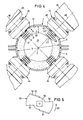
- a plurality of — in the present case four — cutting devices 44 are arranged in a common radial plane 43 to the central longitudinal axis 2. As can be seen in FIG. 4, they are each arranged at equal angular intervals, for example 90 °, and offset because of the separation of the housing 1 in a horizontal plane to this plane.
- Each cutting device 44 has an electric motor 45 which is screwed to a holder 46 which is attached to the housing 1 and passes through it.
- the holder 46 is penetrated by a knife shaft 47 driven by the electric motor 45, which is directed radially into the interior 21.
- the axes 48 of the knife shafts 47 thus lie in the radial plane 43 and intersect the axis 2.
- a plurality of knives 49, 50 are attached to each knife shaft 47 at an axial distance - based on the axes 48.
- the knives 49 are identical to one another; only the knives 50 directly adjacent to the inner wall 31 have wipers 51 bent toward the inner wall 31, by means of which material 29 which may settle between this knife 50 and the inner wall 31 is thrown back into the material ring 32.
- the axial extent e of knives 49, 50 corresponds approximately to the thickness f of the material ring 32.
- the diameter g of the knives 49 and 50 is only slightly smaller than the distance h of the mixing tools 39 which are axially adjacent to one another in this area.
- counter to the conveying direction device 27 can be brought about that the material 29 conveyed as a material ring 32 remains longer in the area of the cutting devices 44, that is to say by exerting an impulse counter to the conveying direction 27 on the material 29.
- the measures described ensure that all not very small material particles inevitably pass through a knife 49 or 50 at least once.
- the knife shafts are driven at a speed such that the peripheral speed on the outer diameter of the knives 49 and 50 is approximately 10 to 40 m / s.
- the diameter g of the knives 49.50 is approximately 50 to 250 mm, depending on the size of the mixer, ie depending on the diameter d of the interior 21 of the housing 1.
- the mixing tools 25 and 39 are designed and set in relation to the axial conveying direction 27 that, taking into account the speed of the mixer 13, an axial feed rate of the material in the mixer between 0.02 m / s and 0.2 m / s is achieved.
- a thickness f of the material ring 32 of 30 to 120 mm is used.
- the axial extent e of the knives 49, 50 in the direction of the axes 48 should be between 40 and 130 mm, so that there can be no material particles in the radially inner region of the material ring 32 that are not separated by at least one knife 49 or 50 can be detected.
- the ratio of the thickness f of the material ring 32 to the diameter d of the housing 1 is 0.06 ⁇ f / d ⁇ 0.24.
- FIG. 5 shows the shape of the knives, only the knife 50 adjacent to the inner wall 31 being shown. Starting from a hub 52, this has two cutting edges 54 leading in the direction of rotation 53 of the cutting devices 44. In the case of the knives 50, the stripper 51 is formed in each case in the region of the rear edge 55 lagging in the direction of rotation 53 by bending the flat knife 50.
- the knives 49 look exactly the same in principle; they only have no wipers.
- Materials 29 that tend to agglomerate are preferably wetted with liquid binder in the mixer. These agglomerates formed in the wetting zone b after the supply of the binder are completely dissolved by the cutting devices 44.
- paper fibers can be wetted with glue, which are then used to manufacture plasterboard.
- other materials that agglomerate after wetting can be wetted with a liquid as part of a so-called material ring mixture.
Abstract
Description
Die Erfindung betrifft einen Mischer nach dem Oberbegriff des Anspruches 1.The invention relates to a mixer according to the preamble of claim 1.
Mischer der gattungsgemäßen Art, die auch als Ringschichtmischer bezeichnet werden, sind in großer Zahl, beispielsweise aus der DE-PS 20 57 594 (entsprechend US-PS 3 734 471) bekannt. Insbesondere zum Beleimen von Holzfasern sind bei derartigen Ringschichtmischern besondere Maßnahmen in Form von spitz zur Behälterwand hin zulaufenden Mischwerkzeugen ergriffen worden, um die nach dem Beleimen zum Agglomerieren neigenden Fasern wieder aufzulösen, wie aus der DE-OS 24 38 818 (entsprechend US-PS 4 006 887) bekannt ist. Diese Maßnahmen haben aber nicht zu dem gewünschten Erfolg, d.h. einer Auflösung der Agglomerate geführt.Mixers of the generic type, which are also referred to as ring-layer mixers, are known in large numbers, for example from DE-PS 20 57 594 (corresponding to US Pat. No. 3,734,471). In particular for gluing wood fibers, special measures have been taken in the form of mixing tools tapering towards the container wall in order to dissolve the fibers that tend to agglomerate after gluing, as described in DE-OS 24 38 818 (corresponding to US Pat. No. 4 006 887) is known. However, these measures have not led to the desired success, that is to say a dissolution of the agglomerates.
Um die Auflösung von Agglomeraten zu unterstützen, wurde die Verweilzeit des benetzten Materials im Mischer erhöht, indem am Auslaß einstellbare oder geregelt einstellbare Auslaßklappen vorgesehen wurden, durch die ein einstellbarer bzw. regelbarer Rückstau auf das Material ausgeübt wurde, um es so länger der auflösenden Wirkung der besonderen Werkzeuge auszusetzen. Dies führte zu erheblichen Materialanbackungen im Auslaßbereich, was auch nicht wünschenswert war.In order to support the dissolution of agglomerates, the residence time of the wetted material in the mixer was increased by providing adjustable or regulated outlet flaps at the outlet, through which an adjustable or adjustable back pressure was exerted on the material in order to prolong the dissolving effect to expose the special tools. This led to considerable material caking in the outlet area, which was also not desirable.
Der Erfindung liegt die Aufgabe zugrunde, einen Mischer der gattungsgemäßen Art so weiterzubilden, daß Agglomerate gezielt und zuverlässig aufgelöst werden, wobei gleichzeitig eine hohe Durchsatzleistung und eine hohe Gleichmäßigkeit der Benetzung erreicht werden sollen.The invention is based on the object of developing a mixer of the generic type in such a way that agglomerates are dissolved in a targeted and reliable manner, at the same time achieving a high throughput and a high uniformity of wetting.
Diese Aufgabe wird erfindungsgemäß durch die Merkmale im Kennzeichnungsteil des Anspruches 1 gelöst. Durch die erfindungsgemäßen Maßnahmen wird sichergestellt, daß das benetzte Material, das in hohem Maße Agglomerate gebildet hat, unmittelbar vor Erreichen des Auslasses durch die Schneideinrichtungen geführt wird, wobei sichergestellt ist, daß jedes Agglomerat mindestens einmal, vorzugsweise aber mehrmals mit einem Messer in Kontakt kommt und aufgelöst wird. Die den Bereich der Schneideinrichtungen verlassenden benetzten nichtagglomerierten Materialpartikel werden unmittelbar dem Auslaß zugeführt und können nicht aufs neue agglomerieren. Die Anzahl der Schneideinrichtungen richtet sich nach der Größe des Mischers und dem Verhältnis der Umfangsgeschwindigkeit der Mischwerkzeuge zur axialen Fließgeschwindigkeit des Materials. Dieses Verhältnis muß so gewählt werden, daß sämtliche Materialpartikel mit Sicherheit beim Passieren der Schneideinrichtungen von diesen erfaßt werden. Wenn eine größere Anzahl von Schneideinrichtungen am gesamten Umfang des Gehäuses des Mischers verteilt angeordnet sind, kann mit einer wesentlich größeren axialen Fördergeschwindigkeit des Materials gearbeitet werden. Auf diese Weise ist es möglich, mit einem Mischer von vorgegebener Größe bei gleicher Mischintensität eine höhere Durchsatzleistung zu erreichen. Es hat sich gezeigt, daß die Agglomeratbildung bei fasrigem, mit Bindemittel zu benetzendem Material durch die Abrollbewegung des Materials an der Innenwand des Gehäuses stattfindet. Wenn nicht - wie vorstehend erläutert - fasriges Material, wie Papierfasern, oder auch Holzfasern, benetzt, insbesondere beleimt werden, sondern wenn Pulver, wie beispielsweise Kalk, benetzt wird, dann können Agglomerate, d.h. Zusammenballungen von mehreren Millimetern Durchmessern zerschlagen werden; andererseits können hier die beim Beetzen gezielt hergestellten Granulate mit einem Durchmesser von beispielsweise weniger als 1 mm erhalten bleiben.This object is achieved by the features in the characterizing part of claim 1. The measures according to the invention ensure that the wetted material, which has largely formed agglomerates, is passed through the cutting devices immediately before reaching the outlet, it being ensured that each agglomerate comes into contact with a knife at least once, but preferably several times and is dissolved. The wetted, non-agglomerated material particles leaving the area of the cutting devices are fed directly to the outlet and cannot agglomerate again. The number of cutting devices depends on the size of the mixer and the ratio of the peripheral speed of the mixing tools the axial flow rate of the material. This ratio must be chosen so that all material particles are reliably grasped by them as they pass the cutting devices. If a larger number of cutting devices are arranged distributed over the entire circumference of the housing of the mixer, it is possible to work with a substantially greater axial conveying speed of the material. In this way it is possible to achieve a higher throughput with a mixer of a predetermined size with the same mixing intensity. It has been shown that the formation of agglomerates in fibrous material to be wetted with binder takes place by the rolling movement of the material on the inner wall of the housing. If - as explained above - fibrous material, such as paper fibers or also wood fibers, is not wetted, in particular glued, but if powder, such as lime, is wetted, agglomerates, ie agglomerations of several millimeters in diameter, can be broken up; on the other hand, the granules with a diameter of less than 1 mm, for example, which are specifically produced during the wetting can be retained.
Weitere Merkmale, Vorteile und Einzelheiten der Erfindung ergeben sich aus den Unteransprüchen und der nachfolgenden Beschreibung eines Ausführungsbeispieles anhand der Zeichnung. Es zeigt
- Fig. 1 einen Mischer gemäß der Erfindung in einem vertikalen Längsschnitt,
- Fig. 2 einen Querschnitt durch den Mischer gemäß der Schnittlinie II-II in Fig. 1,
- Fig. 3 einen Querschnitt durch den Mischer gemäß der Schnittlinie III-III in Fig. 1,
- Fig. 4 einen Querschnitt durch das Gehäuse im Bereich der Schneideinrichtungen ohne Darstellung des Mischwerks und
- Fig. 5 eine Draufsicht auf ein Messer einer Schneideinrichtung des Mischers.
- 1 shows a mixer according to the invention in a vertical longitudinal section,
- 2 shows a cross section through the mixer according to section line II-II in FIG. 1,
- 3 shows a cross section through the mixer according to section line III-III in FIG. 1,
- Fig. 4 shows a cross section through the housing in the area of the cutting devices without showing the mixer and
- Fig. 5 is a plan view of a knife of a cutting device of the mixer.
Der in der Zeichnung dargestellte Mischer weist ein im wesentlichen zylindrisches Gehäuse 1 auf, das in einer Horizontalebene geteilt ist, die durch eine horizontale Mittel-Längs-Achse 2 des Gehäuses gelegt ist. Es besteht insofern aus einem halbzylindrischen GehäuseUnterteil 3 und einem ebenfalls halbzylindrischen Gehäuse-Oberteil 4, die auf einer Seite mittels Schwenkgelenken 5 miteinander verbunden sind und die auf der gegenüberliegenden Seite mittels leicht lösbarer Kniehebel-Verschlüsse 6 miteinander verbindbar sind, so daß nach Lösen dieser Verschlüsse 6 das mit einem Gegengewicht 7 austarierte Gehäuse-Oberteil 4 leicht vom Unterteil 3 hoch- und weggeschwenkt werden kann.The mixer shown in the drawing has a substantially cylindrical housing 1 which is divided in a horizontal plane which is laid through a horizontal central-
Das Gehäuse 1 ist an seinen Stirnseiten mit Stirnwänden 8,9 abgeschlossen, die auch das Unterteil 3 tragen und in Maschinenlagern 10,11 enden. Diese Maschinenlager 10,11 stützen sich auf einem Fundament 12 ab.The housing 1 is closed at its end faces with
Konzentrisch zur Mittel-Längs-Achse 2 ist im Gehäuse 1 ein Mischwerk 13 angeordnet, dessen Welle 14 abgedichtet durch die Stirnwände 8,9 an beiden Enden des Gehäuses 1 herausgeführt ist. Die Welle 14 ist in Wellenlagern 15,16 gelagert, die ebenfalls auf den Maschinenlagern 10,11 abgestützt sind. An einem Ende der Welle 14 ist an dieser ein Riemenrad 17 drehfest befestigt, über das ein Antriebsriemen 18 geführt ist, der wiederum über ein Riemenantriebsritzel 19 eines Antriebsmotors 20 geführt ist, der auch auf dem Fundament 12 abgestützt und befestigt ist.A
An einem - in Fig. 1 rechten - Ende des Gehäuses 1 mündet in dessen Innenraum 21 ein Material-Zuführstutzen 22, der auf dem Oberteil 4 angebracht ist und - wie aus Fig. 2 hervorgeht - etwa tangential in den Innenraum 21 einmündet. Am entgegengesetzten - in Fig. 1 also linken - Ende des Gehäuses 1 mündet aus dessen Innenraum 21 ein Material-Auslaßstutzen 23, der ebenfalls angenähert tangential zum Innenraum angeordnet ist, wie Fig. 3 entnehmbar ist. Wie der Zeichnung entnehmbar ist, ist das Gehäuse 1 doppelwandig ausgebildet, d.h. es weist einen Temperiermantel 24 auf, durch den ein Temperiermedium, insbesondere also Kühlwasser, aber auch ein Heizmedium, geführt werden kann.At one - in Fig. 1 right - end of the housing 1 opens into the
An der Welle 14 des Mischwerks 13 befinden sich zahlreiche Mischwerkzeuge unterschiedlichen Aufbaus. Im Bereich des Material-Zuführstutzens 22 ist eine Einzugszone a ausgebildet, in der auf der Welle 14 Einzugs- bzw. Beschleunigungs-Werkzeuge 25 angebracht sind. Diese bestehen im wesentlichen aus relativ großen Schaufeln 26, die in axialer Förderrichtung 27 und in Drehrichtung 28 des Mischwerks 13 angestellt sind, so daß sie das durch den Zuführstutzen 22 zugeführte schüttfähige Material 29 in Drehrichtung 28 beschleunigen und in axialer Förderrichtung 27 in Bewegung setzen. Die Schaufeln 26 sind mittels Armen 30 an der Welle 14 befestigt. Wie Fig. 1 entnehmbar ist, überdecken sich die Schaufeln 26 in axialer Richtung vollständig; außerdem reichen sie bis nahe an die Innenwand 31 des Gehäuses 1, so daß keine Toträume entstehen, in denen Material 29 abgelagert werden könnte. Das Mischwerk 13 wird mit 20- bis 40-facher kritischer Drehzahl angetrieben, so daß das Material 29 bereits unmittelbar hinter dem Zuführstutzen 22 sich in Form eines Materialringes 32 an die Innenwand 31 des Gehäuses 1 legt, an der es schraubenlinienförmig durch den Innenraum 21 des Gehäuses 1 gefördert wird. Unter der kritischen Drehzahl versteht man die Drehzahl des Mischwerkes 13, bei der an den radial äußeren Enden der Werkzeuge Erdbeschleunigung auftritt.There are numerous mixing tools of various designs on the shaft 14 of the
An die Einzugszone a schließt sich in Förderrichtung 27 eine Benetzungszone b an. In dieser Benetzungszone b sind Flüssigkeitszugabe- und Misch-Werkzeuge 33 an der Welle 14 angebracht. Diese Werkzeuge 33 können als etwa zylindrische, bis nahe an die Innenwand 31 herangeführte Mischarme ausgebildet sein, die - wie ebenfalls Fig. 1 entnehmbar ist - in axialer Richtung einander überlappen, so daß ebenfalls auch in der Benetzungszone b keine Toträume entstehen können, in denen Material 29 nicht intensiv beaufschlagt wird.A wetting zone b adjoins the feed zone a in the conveying
Die Flüssigkeitszugabe- und Misch-Werkzeuge 33 sind mit einem Flüssigkeits-Zuführrohr 34 verbunden, das konzentrisch zur Achse 2 durch einen Wellenhohlraum 35 der hohl ausgebildeten Welle 14 geführt ist. Dieses Flüssigkeits-Zuführrohr 34 besitzt im Bereich der Benetzungszone b Flüssigkeits-Austrittsöffnungen 36. Aus diesen Austrittsöffnungen 30 tritt durch das Zuführrohr 34 von einer nicht dargestellten Pumpe zugeführte Flüssigkeit in den Wellenhohlraum 35. Aufgrund der hohen Drehzahl und der daraus resultierenden Zentrifugalkräfte wird diese Flüssigkeit in die einzelnen Werkzeuge 33 geschleudert, durchfließt diese und wird von diesen an ihrem radial äußeren Ende in Form von feinstzerteilter Flüssigkeit 37 in den Materialring 32 abgegeben, der durch die Werkzeuge 33 auch in der Benetzungszone b aufrechterhalten wird. Die Umlaufgeschwindigkeit des Materialringes 32 in Drehrichtung 28 ist etwa halb so groß wie die Umlaufgeschwindigkeit der Werkzeuge 33 im radial äußeren Bereich. Die Ausgestaltung der Flüssigkeitszugabe- und Misch-Werkzeuge 33 kann hinsichtlich der Flüssigkeitsführung auch so sein, wie in der DE-OS 24 38 818 (entsprechend US-PS 4 006 887) dargestellt und beschrieben ist.The liquid addition and mixing tools 33 are connected to a
An die Benetzungszone b schließt sich eine bis zum Auslaßstutzen 23, also etwa bis zum axialen Ende des Innenraums 21 reichende Nachmischzone c an. In dieser Nachmischzone c sind Misch-Werkzeuge 38 angeordnet, die in ihrem äußeren Aufbau dem der Werkzeuge 33 glei chen können, aber nicht mehr zur Flüssigkeitszufuhr dienen. Andererseits können auch etwa hakenförmige Misch-Werkzeuge 39 angebracht sein, die einen zylindrischen rohrförmigen, sich radial erstreckenden Abschnitt 40 und einen sich verjüngenden, in Drehrichtung 28 vorlaufenden, gegenüber dem Abschnitt 40 abgeknickten, bis nahe an die Innenwand 31 reichenden Haken-Abschnitt 41 aufweisen. Diese Werkzeuge 39 können beispielsweise im einzelnen ausgebildet sein, wie es in der DE-OS 27 31 767 (entsprechend US-PS 4 183 676) dargestellt und beschrieben ist. Diese Werkzeuge 39 sind mit der Welle 14 in der Weise mittels einer Überwurfmutter 39a verschraubt, daß sie um ihre radiale Längsachse 42 gedreht werden können, d.h. der Haken-Abschnitt 41 kann gegen die axiale Förderrichtung 27 oder in dieser Förderrichtung 27 angestellt werden, so daß auf das Material 29 entweder ein die Axialbewegung verzögernder oder beschleunigender Impuls ausgeübt werden kann. Während die rein stab-oder stangenförmigen Werkzeuge 33 bzw. 38 nur in Drehrichtung 28 Impulse auf das Material 29 ausüben, kann so durch die Werkzeuge 39 auch der axiale Durchlauf wieder verzögert bzw. beschleunigt werden. Am Ende der Nachmischzone c wird das Material durch den Material-Auslaßstutzen 23 ausgeworfen. Die hakenförmigen Misch-Werkzeuge 39 können auch durch andere Misch-Werkzeuge ersetzt werden, und zwar insbesondere solche, die durch Veränderung des Anstellwinkels einen verstärkten Axial-Impuls oder eine Abbremsung auf das Material 29 ausüben. Derartige Misch-Werkzeuge sind beispielsweise aus der DE-PS 20 57 594 (entsprechend US-PS 3 734 471) bekannt.The wetting zone b is followed by a post-mixing zone c which extends as far as the
Unmittelbar vor dem Auslaßstutzen 23 sind in einer gemeinsamen Radialebene 43 zur Mittel-Längs-Achse 2 mehrere - im vorliegenden Fall vier - Schneideinrichtungen 44 angeordnet. Sie sind - wie Fig. 4 entnehmbar ist - jeweils in gleichen Winkelabständen, beispielsweise also 90°, und wegen der Trennung des Gehäuses 1 in einer horizontalen Ebene zu dieser Ebene versetzt angeordnet. Jede Schneideinrichtung 44 weist einen Elektromotor 45 auf, der an einer am Gehäuse 1 angebrachten und diese durchsetzenden Halterung 46 angeschraubt ist. Die Halterung 46 wird von einer von dem Elektromotor 45 angetriebenen Messerwelle 47 durchsetzt, die radial in den Innenraum 21 gerichtet ist. Die Achsen 48 der Messerwellen 47 liegen also in der Radialebene 43 und schneiden die Achse 2. An jeder Messerwelle 47 sind mehrere Messer 49,50 in axialem Abstand - bezogen auf die Achsen 48 - angebracht. Die Messer 49 sind untereinander gleich; lediglich die unmittelbar der Innenwand 31 benachbarten Messer 50 weisen zur Innenwand 31 hin umgebogene Abstreifer 51 auf, mittels derer zwischen diesem Messer 50 und der Innenwand 31 sich möglicherweise absetzendes Material 29 in den Materialring 32 zurückgeschleudert wird. Die axiale Erstreckung e von Messern 49,50 entspricht etwa der Dicke f des Materialrings 32.Immediately in front of the
Der Durchmesser g der Messer 49 bzw. 50 ist nur geringfügig kleiner als der Abstand h der in diesem Bereich axial einander benachbarten Misch-Werkzeuge 39. Durch entsprechende Anstellung der in Förderrichtung 27 den Schneideinrichtungen 44 unmittelbar nachgeordneten Misch-Werkzeuge 39 entgegen der Förderrich tung 27 kann bewirkt werden, daß das als Materialring 32 geförderte Material 29 länger im Bereich der Schneideinrichtungen 44 verbleibt, indem also ein entgegen der Förderrichtung 27 wirkender Impuls auf das Material 29 ausgeübt wird. Durch die geschilderten Maßnahmen wird erreicht, daß alle nicht sehr kleinen Materialpartikel zwangsläufig mindestens einmal ein Messer 49 oder 50 passieren. Die Messerwellen werden mit einer Drehzahl so angetrieben, daß die Umfangsgeschwindigkeit am Außendurchmesser der Messer 49 bzw. 50 etwa 10 bis 40 m/s beträgt. Der Durchmesser g der Messer 49,50 beträgt etwa 50 bis 250 mm, und zwar je nach Größe des Mischers, d.h. je nach Durchmesser d des Innenraums 21 des Gehäuses 1. Die Mischwerkzeuge 25 und 39 sind so ausgebildet und gegenüber der axialen Förderrichtung 27 angestellt, daß unter Berücksichtigung der Drehzahl des Mischwerks 13 eine axiale Vorschubgeschwindigkeit des Materials im Mischer zwischen 0,02 m/s und 0,2 m/s erreicht wird. Bei einem Mischer mit einem Durchmesser d von beispielsweise 500 mm wird mit einer Dicke f des Materialrings 32 von 30 bis 120 mm gearbeitet. Die axiale Erstreckung e der Messer 49,50 in Richtung der Achsen 48 sollte hierbei zwischen 40 und 130 mm liegen, so daß mit Sicherheit auch im radial inneren Bereich des Materialrings 32 keine Materialpartikel vorhanden sein können, die nicht von mindestens einem Messer 49 bzw. 50 erfaßt werden. Für das Verhältnis der Dicke f des Materialringes 32 zum Durchmesser d des Gehäuses 1 gilt 0,06≦f/d≦0,24.The diameter g of the
Die Form der Messer ist Fig. 5 zu entnehmen, wobei nur das der Innenwand 31 benachbarte Messer 50 dargestellt ist. Dieses weist ausgehend von einer Nabe 52 zwei in Drehrichtung 53 der Schneideinrichtungen 44 voreilende Schneiden 54 auf. Bei den Messern 50 ist der Abstreifer 51 jeweils im Bereich der in Drehrichtung 53 nacheilenden also rückwärtigen Kante 55 durch Umbiegen des flachen Messers 50 gebildet. Die Messer 49 sehen im Grundsätz genauso aus; sie weisen lediglich keinen Abstreifer auf.5 shows the shape of the knives, only the
In dem Mischer werden bevorzugt in hohem Maße zum Agglomerieren neigende Materialien 29, wie beispielsweise Papierfasern und Holzfasern, mit flüssigem Bindemittel benetzt. Diese nach der Zuführung des Bindemittels in der Benetzungszone b entstehenden Agglomerate werden durch die Schneideinrichtungen 44 vollständig aufgelöst. Beispielsweise können Papierfasern mit Leim benetzt werden, die anschließend zur Herstellung von Gips-Karton-Platten eingesetzt werden. Andererseits ist es auch möglich, ein Vorgemisch von Gips und Papierfasern mit einem Gemisch aus Bindemittel und Wasser zu benetzen, so daß klumpenfreies und agglomeratfreies Gips-Papierfaser-Bindemittel-Wasser-Gemisch durch den Auslaßstutzen 23 abgegeben wird, das unmittelbar zu Gips- Karton-Platten weiterverarbeitet werden kann. In gleicher Weise können andere nach dem Benetzen agglomerierende Materialien im Rahmen einer sogenannten Materialring-Mischung mit einer Flüssigkeit benetzt werden.
Gleichermaßen ist andererseits eine Granulierung von Pulver mit Flüssigkeit zu Granulaten mit einer Korngröße von weniger als 1 mm möglich, wobei in diesem Fall Agglomerate mit erheblich größerem Durchmesser von beispielsweise 3 bis 6 mm, in den Schneideinrichtungen 44 vollständig zerschlagen werden, ohne daß die sehr viel feineren Granulate hierbei zerstört werden. Beim Benetzen solcher pulvrigen Stoffe mit Flüssigkeit, beispielsweise Gips mit Wasser, wird mit einem dünneren Materialring 32 gearbeitet, wie er vorstehend angegeben wurde. Dagegen wird beim Benetzen von fasrigen Materialien mit einer größeren Dicke f des Materialrings 32 gearbeitet.Similarly, granulation of powder with liquid into granules with a grain size of less than 1 mm is possible, in which case agglomerates with a considerably larger diameter of, for example, 3 to 6 mm, are completely broken up in the
Claims (6)
Priority Applications (1)
| Application Number | Priority Date | Filing Date | Title |
|---|---|---|---|
| AT89115813T ATE88661T1 (en) | 1988-11-24 | 1989-08-28 | CONTINUOUSLY WORKING MIXER. |
Applications Claiming Priority (2)
| Application Number | Priority Date | Filing Date | Title |
|---|---|---|---|
| DE3839671 | 1988-11-24 | ||
| DE3839671A DE3839671A1 (en) | 1988-11-24 | 1988-11-24 | CONTINUOUSLY WORKING MIXERS |
Publications (2)
| Publication Number | Publication Date |
|---|---|
| EP0370181A1 true EP0370181A1 (en) | 1990-05-30 |
| EP0370181B1 EP0370181B1 (en) | 1993-04-28 |
Family
ID=6367805
Family Applications (1)
| Application Number | Title | Priority Date | Filing Date |
|---|---|---|---|
| EP89115813A Revoked EP0370181B1 (en) | 1988-11-24 | 1989-08-28 | Continuously working mixer |
Country Status (8)
| Country | Link |
|---|---|
| US (1) | US5018673A (en) |
| EP (1) | EP0370181B1 (en) |
| JP (1) | JPH02180628A (en) |
| AT (1) | ATE88661T1 (en) |
| BR (1) | BR8905664A (en) |
| CA (1) | CA2003118A1 (en) |
| DE (2) | DE3839671A1 (en) |
| ZA (1) | ZA898730B (en) |
Cited By (4)
| Publication number | Priority date | Publication date | Assignee | Title |
|---|---|---|---|---|
| WO1995011206A1 (en) * | 1993-10-20 | 1995-04-27 | Universal Greening Pty Ltd | Composting apparatus |
| EP0812616A1 (en) * | 1996-06-11 | 1997-12-17 | Gebrüder Lödige Maschinenbaugesellschaft mbH | Device for disaggregating materials |
| WO2010081477A1 (en) * | 2009-01-13 | 2010-07-22 | Biogasol Ipr Aps | Apparatus for rapid mixing of media and method |
| CZ306488B6 (en) * | 2015-12-18 | 2017-02-08 | Rudolf Ryzner | A device for dipping, mixing and enrichment of organic substrates |
Families Citing this family (29)
| Publication number | Priority date | Publication date | Assignee | Title |
|---|---|---|---|---|
| JP2696435B2 (en) * | 1991-03-26 | 1998-01-14 | 顯治 前田 | Concrete kneading method and apparatus |
| DE4124984C2 (en) * | 1991-07-27 | 1995-04-27 | Babcock Bsh Ag | Use of a mixing, granulating and drying device |
| DE4132906C2 (en) * | 1991-10-04 | 1994-09-29 | Loedige Maschbau Gmbh Geb | Using a plasterboard reconditioning machine |
| DE19503266C2 (en) * | 1995-02-02 | 2003-06-18 | Suma Sondermaschinen Gmbh | Shredding device for installation in pipelines |
| US5580170A (en) * | 1995-10-06 | 1996-12-03 | Ferro-Tech, Inc. | Mixing and conditioning machine |
| DE19740676C2 (en) * | 1997-09-16 | 2003-07-17 | Fraunhofer Ges Forschung | Process for gluing fibers |
| ES2189557B1 (en) * | 1999-04-29 | 2004-10-16 | Ekolur, S.L. | FEEDER AND MIXER OF PALLETS FOR THE PROJECTION OF THE CONCRETE OR GUNITA AND THE COMPOS. |
| US6414054B1 (en) | 1999-12-21 | 2002-07-02 | General Electric Company | Continuous preparation of heat-vulcanizable silicone compositions |
| US6548574B1 (en) * | 1999-12-21 | 2003-04-15 | General Electric Company | Heat-vulcanizable silicone compositions from premix |
| EP1157736A1 (en) * | 2000-05-20 | 2001-11-28 | Glatt Maschinen- und Apparatebau AG | Device and process for the quasi-continuous treatment of granular material |
| US6511217B1 (en) * | 2000-11-03 | 2003-01-28 | General Electric Company | Method and system to compound silicone compositions |
| DE10059881B4 (en) | 2000-12-01 | 2005-06-02 | Fraunhofer-Gesellschaft zur Förderung der angewandten Forschung e.V. | Plant for fiber preparation |
| DE10126783A1 (en) * | 2001-06-01 | 2003-01-02 | Glatt Systemtechnik Gmbh | Device for feeding a drying gas into a mixing granulator |
| DE10215806A1 (en) * | 2002-04-10 | 2003-10-23 | Buehler Ag | Flow smoothing mixer |
| US7563017B1 (en) * | 2002-09-06 | 2009-07-21 | Bracegirdle Paul E | Process for mixing congealable materials such as cement, asphalt, and glue with fibers from waste carpet |
| ES2264356B1 (en) * | 2004-11-11 | 2008-01-01 | Tecnicas De Mezclado, S.L. | APPARATUS FOR THE DISPERSION OF COLORS AND PIGMENTS IN MIXTURES OF PULVERULENT PRODUCTS. |
| DE102009057916B4 (en) * | 2009-05-15 | 2015-04-02 | Siempelkamp Maschinen- Und Anlagenbau Gmbh | Method and apparatus for continuous mixing of fibers with a binder |
| US9194092B2 (en) * | 2010-01-26 | 2015-11-24 | Mark Kline | Mechanism for automated mixing of liquid solutions and granular materials |
| JP2016087808A (en) * | 2014-10-30 | 2016-05-23 | 株式会社タイガーマシン製作所 | Material supply box device |
| JP6834960B2 (en) * | 2015-08-26 | 2021-02-24 | 株式会社サタケ | Superheated steam sterilizer |
| US11224990B2 (en) * | 2016-08-05 | 2022-01-18 | United States Gypsum Company | Continuous methods of making fiber reinforced concrete panels |
| US10272399B2 (en) * | 2016-08-05 | 2019-04-30 | United States Gypsum Company | Method for producing fiber reinforced cementitious slurry using a multi-stage continuous mixer |
| US10981294B2 (en) | 2016-08-05 | 2021-04-20 | United States Gypsum Company | Headbox and forming station for fiber-reinforced cementitious panel production |
| US11173629B2 (en) * | 2016-08-05 | 2021-11-16 | United States Gypsum Company | Continuous mixer and method of mixing reinforcing fibers with cementitious materials |
| CN109876720A (en) * | 2017-12-06 | 2019-06-14 | 天津发洋环保科技有限公司 | A kind of photo-catalytic emulsion tinuous production |
| JP6889924B2 (en) * | 2018-01-17 | 2021-06-18 | 株式会社切川物産 | Stirring mixer |
| CN109926432A (en) * | 2019-03-15 | 2019-06-25 | 深圳市发现环保科技有限公司 | Solid organic matters fine crusher |
| CN110625814B (en) * | 2019-09-30 | 2021-02-02 | 广州胜帆新材料科技有限公司 | Rapid forming device and method for producing arc-shaped GRG (glass-fiber-reinforced glass) plate |
| RU2728441C1 (en) * | 2019-10-23 | 2020-07-29 | Федеральное государственное бюджетное образовательное учреждение высшего образования "Поволжский государственный технологический университет" | Device for production of wood concrete |
Citations (8)
| Publication number | Priority date | Publication date | Assignee | Title |
|---|---|---|---|---|
| CH367379A (en) * | 1957-12-20 | 1963-02-15 | Loedige Wilhelm | Method and device for mixing and comminuting powdery, fine-grained and fibrous mixed goods |
| FR1511391A (en) * | 1967-02-14 | 1968-01-26 | Apparatus for mixing and, where appropriate, breaking up and / or moistening powdery, fine-grained or fibrous substances | |
| DE1432028A1 (en) * | 1964-02-18 | 1968-10-31 | Draiswerke Gmbh | Method for operating mixing machines and the associated mixing machine |
| US3506201A (en) * | 1965-12-17 | 1970-04-14 | Draiswerke Gmbh | Trough mixer having a dosing arrangement for mixing fibrous materials |
| DE1782585A1 (en) * | 1968-09-20 | 1971-10-14 | Draiswerke Gmbh | Mixer |
| CH525702A (en) * | 1970-11-24 | 1972-07-31 | Draiswerke Gmbh | Method and device for the continuous mixing or wetting of solids with liquids |
| DE2924326A1 (en) * | 1979-06-15 | 1981-01-08 | Loedige Maschbau Gmbh Geb | Viscous paste drying method - by heating in vacuum after forming azeotropic mix. with added organic solvent |
| DE3711987A1 (en) * | 1987-04-09 | 1988-10-27 | Durmersheim Baustoffwerke | Mixing and distribution apparatus for mixtures of pulverulent to granular solids |
Family Cites Families (13)
| Publication number | Priority date | Publication date | Assignee | Title |
|---|---|---|---|---|
| DE1245577B (en) * | 1960-04-04 | 1967-07-27 | Fritz Loedige | Mixing device for powdery, fine-grained or fibrous plastics |
| DE1184325B (en) * | 1960-07-30 | 1964-12-31 | Draiswerke Gmbh | Mixer |
| US3162428A (en) * | 1961-07-15 | 1964-12-22 | Loedige Wilhelm | Process for mixing and wetting solid materials |
| DE1297325B (en) * | 1966-11-03 | 1969-06-12 | Draiswerke Gmbh | Trough mixer with a spraying device for mixing fibrous materials |
| US3522934A (en) * | 1968-08-08 | 1970-08-04 | Ulrich Walter | Method and apparatus for producing a homogeneous mixture of granular and viscous substances |
| GB1307173A (en) * | 1971-07-30 | 1973-02-14 | Herfeld Kg Dr | Method of mixing materials |
| DE2240454A1 (en) * | 1972-08-17 | 1974-03-07 | Rheinstahl Ag | DEVICE FOR CRUSHING AGGLOMERATES |
| US4006887A (en) * | 1974-08-13 | 1977-02-08 | Draiswerke Gmbh | Device for continuous coating of fibers |
| DE2625923A1 (en) * | 1976-06-10 | 1977-12-22 | Fritz Loedige | Rotary mixer esp. for chipboard prodn. - has glue feed nozzles supplied from distributor head to equalise distribution |
| DE3105549A1 (en) * | 1981-02-16 | 1982-09-02 | Draiswerke Gmbh | Process and device for gluing wood chips |
| DE3406648A1 (en) * | 1984-02-24 | 1985-09-12 | Ruberg-Mischtechnik KG, 4790 Paderborn | Mixing machine for continuous mixing processes |
| US4705222A (en) * | 1985-05-03 | 1987-11-10 | Processall, Inc. | Multipurpose mixer |
| DE3612853A1 (en) * | 1986-04-16 | 1987-11-05 | Bhs Bayerische Berg | Flow mixer |
-
1988
- 1988-11-24 DE DE3839671A patent/DE3839671A1/en not_active Withdrawn
-
1989
- 1989-08-28 DE DE8989115813T patent/DE58904203D1/en not_active Expired - Fee Related
- 1989-08-28 AT AT89115813T patent/ATE88661T1/en not_active IP Right Cessation
- 1989-08-28 EP EP89115813A patent/EP0370181B1/en not_active Revoked
- 1989-11-06 BR BR898905664A patent/BR8905664A/en not_active Application Discontinuation
- 1989-11-15 ZA ZA898730A patent/ZA898730B/en unknown
- 1989-11-15 JP JP1295147A patent/JPH02180628A/en active Pending
- 1989-11-16 CA CA002003118A patent/CA2003118A1/en not_active Abandoned
- 1989-11-20 US US07/438,271 patent/US5018673A/en not_active Expired - Fee Related
Patent Citations (8)
| Publication number | Priority date | Publication date | Assignee | Title |
|---|---|---|---|---|
| CH367379A (en) * | 1957-12-20 | 1963-02-15 | Loedige Wilhelm | Method and device for mixing and comminuting powdery, fine-grained and fibrous mixed goods |
| DE1432028A1 (en) * | 1964-02-18 | 1968-10-31 | Draiswerke Gmbh | Method for operating mixing machines and the associated mixing machine |
| US3506201A (en) * | 1965-12-17 | 1970-04-14 | Draiswerke Gmbh | Trough mixer having a dosing arrangement for mixing fibrous materials |
| FR1511391A (en) * | 1967-02-14 | 1968-01-26 | Apparatus for mixing and, where appropriate, breaking up and / or moistening powdery, fine-grained or fibrous substances | |
| DE1782585A1 (en) * | 1968-09-20 | 1971-10-14 | Draiswerke Gmbh | Mixer |
| CH525702A (en) * | 1970-11-24 | 1972-07-31 | Draiswerke Gmbh | Method and device for the continuous mixing or wetting of solids with liquids |
| DE2924326A1 (en) * | 1979-06-15 | 1981-01-08 | Loedige Maschbau Gmbh Geb | Viscous paste drying method - by heating in vacuum after forming azeotropic mix. with added organic solvent |
| DE3711987A1 (en) * | 1987-04-09 | 1988-10-27 | Durmersheim Baustoffwerke | Mixing and distribution apparatus for mixtures of pulverulent to granular solids |
Cited By (9)
| Publication number | Priority date | Publication date | Assignee | Title |
|---|---|---|---|---|
| WO1995011206A1 (en) * | 1993-10-20 | 1995-04-27 | Universal Greening Pty Ltd | Composting apparatus |
| EP0812616A1 (en) * | 1996-06-11 | 1997-12-17 | Gebrüder Lödige Maschinenbaugesellschaft mbH | Device for disaggregating materials |
| US5803374A (en) * | 1996-06-11 | 1998-09-08 | Gebrueder Loedige Maschinenbaugesellschaft Mbh | Breakdown tool |
| WO2010081477A1 (en) * | 2009-01-13 | 2010-07-22 | Biogasol Ipr Aps | Apparatus for rapid mixing of media and method |
| AU2010205966B2 (en) * | 2009-01-13 | 2014-06-05 | Biogasol Aps | Apparatus for rapid mixing of media and method |
| CN102271792B (en) * | 2009-01-13 | 2014-09-17 | 拜格索有限公司 | Apparatus for rapid mixing of media and method |
| US8845976B2 (en) | 2009-01-13 | 2014-09-30 | Biogasol Aps | Apparatus for rapid mixing of media and method |
| US9605223B2 (en) | 2009-01-13 | 2017-03-28 | Biogasol Aps | Apparatus for rapid mixing of media and method |
| CZ306488B6 (en) * | 2015-12-18 | 2017-02-08 | Rudolf Ryzner | A device for dipping, mixing and enrichment of organic substrates |
Also Published As
| Publication number | Publication date |
|---|---|
| ATE88661T1 (en) | 1993-05-15 |
| DE3839671A1 (en) | 1990-05-31 |
| EP0370181B1 (en) | 1993-04-28 |
| ZA898730B (en) | 1990-08-29 |
| BR8905664A (en) | 1990-06-05 |
| JPH02180628A (en) | 1990-07-13 |
| CA2003118A1 (en) | 1990-05-24 |
| DE58904203D1 (en) | 1993-06-03 |
| US5018673A (en) | 1991-05-28 |
Similar Documents
| Publication | Publication Date | Title |
|---|---|---|
| EP0370181B1 (en) | Continuously working mixer | |
| DE3532722C2 (en) | ||
| DE1213385C2 (en) | MIXER | |
| DE2709309C3 (en) | Device for discharging flowable material | |
| DE2624048C2 (en) | Continuous mixer | |
| EP0046569A2 (en) | Process and apparatus for mixing solids with liquids | |
| DE661846C (en) | Device for mixing, stirring, dissolving, thickening, kneading, triturating, comminuting or salifying flowable or already powdery masses, preferably for processing cocoa or chocolate masses | |
| DE2702033C2 (en) | Device for continuously adding additional material to a stream of free-flowing base material | |
| DE2428588C2 (en) | Device for gluing chips | |
| EP0304604A2 (en) | Mixer with stirrer and grinder | |
| DE2453810A1 (en) | METHOD AND DEVICE FOR DISPERSING A POWDER IN A LIQUID | |
| DE2456613C2 (en) | DEVICE FOR CONTINUOUS PROCESSING OF GRAINY MATERIAL | |
| EP0716878B1 (en) | Apparatus for manufacturing paint | |
| DE2355671A1 (en) | MIXING MACHINE | |
| DE1089251B (en) | Mixing device for grainy material | |
| DE2438818A1 (en) | Coating wood fibres with adhesive without forming clumps - using a tubular centrifuge incorpd. into pneumatic conveyor pipe | |
| DE1190439B (en) | Device for loosening, mixing, emulsifying, homogenizing, etc. Like. Mixtures of substances that contain poorly soluble solid and liquid components | |
| EP0211230B1 (en) | Installation for mixing solid materials and liquids | |
| DE2219352C2 (en) | Continuously working ring mixer | |
| DE3406648C2 (en) | ||
| DE2831641C2 (en) | Device for shredding wet waste | |
| DE2736812C2 (en) | ||
| DE2511971C3 (en) | Process for the production of polyvinyl chloride mixtures containing additives | |
| EP0036985B1 (en) | Apparatus for producing a mixture from at least one compressible particulate solid and at least a liquid component | |
| DE963688C (en) | Device for handling viscous, doughy, gritty or fibrous masses |
Legal Events
| Date | Code | Title | Description |
|---|---|---|---|
| PUAI | Public reference made under article 153(3) epc to a published international application that has entered the european phase |
Free format text: ORIGINAL CODE: 0009012 |
|
| AK | Designated contracting states |
Kind code of ref document: A1 Designated state(s): AT BE CH DE ES FR GB IT LI NL SE |
|
| 17P | Request for examination filed |
Effective date: 19901119 |
|
| 17Q | First examination report despatched |
Effective date: 19920324 |
|
| GRAA | (expected) grant |
Free format text: ORIGINAL CODE: 0009210 |
|
| AK | Designated contracting states |
Kind code of ref document: B1 Designated state(s): AT BE CH DE ES FR GB IT LI NL SE |
|
| PG25 | Lapsed in a contracting state [announced via postgrant information from national office to epo] |
Ref country code: IT Free format text: LAPSE BECAUSE OF FAILURE TO SUBMIT A TRANSLATION OF THE DESCRIPTION OR TO PAY THE FEE WITHIN THE PRE;WARNING: LAPSES OF ITALIAN PATENTS WITH EFFECTIVE DATE BEFORE 2007 MAY HAVE OCCURRED AT ANY TIME BEFORE 2007. THE CORRECT EFFECTIVE DATE MAY BE DIFFERENT FROM THE ONE RECORDED.SCRIBED TIME-LIMIT Effective date: 19930428 Ref country code: FR Effective date: 19930428 Ref country code: GB Effective date: 19930428 Ref country code: NL Effective date: 19930428 Ref country code: BE Effective date: 19930428 Ref country code: SE Effective date: 19930428 |
|
| REF | Corresponds to: |
Ref document number: 88661 Country of ref document: AT Date of ref document: 19930515 Kind code of ref document: T |
|
| REF | Corresponds to: |
Ref document number: 58904203 Country of ref document: DE Date of ref document: 19930603 |
|
| PG25 | Lapsed in a contracting state [announced via postgrant information from national office to epo] |
Ref country code: ES Free format text: LAPSE BECAUSE OF FAILURE TO SUBMIT A TRANSLATION OF THE DESCRIPTION OR TO PAY THE FEE WITHIN THE PRESCRIBED TIME-LIMIT Effective date: 19930729 |
|
| EN | Fr: translation not filed | ||
| NLV1 | Nl: lapsed or annulled due to failure to fulfill the requirements of art. 29p and 29m of the patents act | ||
| GBV | Gb: ep patent (uk) treated as always having been void in accordance with gb section 77(7)/1977 [no translation filed] |
Effective date: 19930428 |
|
| PLBI | Opposition filed |
Free format text: ORIGINAL CODE: 0009260 |
|
| 26 | Opposition filed |
Opponent name: GEBR. LOEDIGE MASCHINENBAU-GESELLSCHAFT MBH Effective date: 19940126 |
|
| PGFP | Annual fee paid to national office [announced via postgrant information from national office to epo] |
Ref country code: AT Payment date: 19960723 Year of fee payment: 8 Ref country code: CH Payment date: 19960723 Year of fee payment: 8 |
|
| PGFP | Annual fee paid to national office [announced via postgrant information from national office to epo] |
Ref country code: DE Payment date: 19961023 Year of fee payment: 8 |
|
| PG25 | Lapsed in a contracting state [announced via postgrant information from national office to epo] |
Ref country code: AT Free format text: LAPSE BECAUSE OF NON-PAYMENT OF DUE FEES Effective date: 19970828 |
|
| PG25 | Lapsed in a contracting state [announced via postgrant information from national office to epo] |
Ref country code: LI Free format text: LAPSE BECAUSE OF NON-PAYMENT OF DUE FEES Effective date: 19970831 Ref country code: CH Free format text: LAPSE BECAUSE OF NON-PAYMENT OF DUE FEES Effective date: 19970831 |
|
| APAE | Appeal reference modified |
Free format text: ORIGINAL CODE: EPIDOS REFNO |
|
| REG | Reference to a national code |
Ref country code: CH Ref legal event code: PL |
|
| PG25 | Lapsed in a contracting state [announced via postgrant information from national office to epo] |
Ref country code: DE Free format text: LAPSE BECAUSE OF NON-PAYMENT OF DUE FEES Effective date: 19980501 |
|
| APAC | Appeal dossier modified |
Free format text: ORIGINAL CODE: EPIDOS NOAPO |
|
| RDAH | Patent revoked |
Free format text: ORIGINAL CODE: EPIDOS REVO |
|
| RDAG | Patent revoked |
Free format text: ORIGINAL CODE: 0009271 |
|
| STAA | Information on the status of an ep patent application or granted ep patent |
Free format text: STATUS: PATENT REVOKED |
|
| 27W | Patent revoked |
Effective date: 19981229 |
|
| APAH | Appeal reference modified |
Free format text: ORIGINAL CODE: EPIDOSCREFNO |