EP0369561A2 - System and process for making diffractive contact lenses and diffractive intra-ocular lenses - Google Patents
System and process for making diffractive contact lenses and diffractive intra-ocular lenses Download PDFInfo
- Publication number
- EP0369561A2 EP0369561A2 EP89250086A EP89250086A EP0369561A2 EP 0369561 A2 EP0369561 A2 EP 0369561A2 EP 89250086 A EP89250086 A EP 89250086A EP 89250086 A EP89250086 A EP 89250086A EP 0369561 A2 EP0369561 A2 EP 0369561A2
- Authority
- EP
- European Patent Office
- Prior art keywords
- lens
- mask
- laser
- optical system
- zone plate
- Prior art date
- Legal status (The legal status is an assumption and is not a legal conclusion. Google has not performed a legal analysis and makes no representation as to the accuracy of the status listed.)
- Ceased
Links
Images


Classifications
-
- G—PHYSICS
- G02—OPTICS
- G02C—SPECTACLES; SUNGLASSES OR GOGGLES INSOFAR AS THEY HAVE THE SAME FEATURES AS SPECTACLES; CONTACT LENSES
- G02C7/00—Optical parts
- G02C7/02—Lenses; Lens systems ; Methods of designing lenses
- G02C7/04—Contact lenses for the eyes
-
- B—PERFORMING OPERATIONS; TRANSPORTING
- B29—WORKING OF PLASTICS; WORKING OF SUBSTANCES IN A PLASTIC STATE IN GENERAL
- B29D—PRODUCING PARTICULAR ARTICLES FROM PLASTICS OR FROM SUBSTANCES IN A PLASTIC STATE
- B29D11/00—Producing optical elements, e.g. lenses or prisms
- B29D11/00009—Production of simple or compound lenses
- B29D11/00038—Production of contact lenses
-
- B—PERFORMING OPERATIONS; TRANSPORTING
- B29—WORKING OF PLASTICS; WORKING OF SUBSTANCES IN A PLASTIC STATE IN GENERAL
- B29D—PRODUCING PARTICULAR ARTICLES FROM PLASTICS OR FROM SUBSTANCES IN A PLASTIC STATE
- B29D11/00—Producing optical elements, e.g. lenses or prisms
- B29D11/00009—Production of simple or compound lenses
- B29D11/00317—Production of lenses with markings or patterns
- B29D11/00326—Production of lenses with markings or patterns having particular surface properties, e.g. a micropattern
-
- B—PERFORMING OPERATIONS; TRANSPORTING
- B29—WORKING OF PLASTICS; WORKING OF SUBSTANCES IN A PLASTIC STATE IN GENERAL
- B29D—PRODUCING PARTICULAR ARTICLES FROM PLASTICS OR FROM SUBSTANCES IN A PLASTIC STATE
- B29D11/00—Producing optical elements, e.g. lenses or prisms
- B29D11/00009—Production of simple or compound lenses
- B29D11/00432—Auxiliary operations, e.g. machines for filling the moulds
- B29D11/00461—Adjusting the refractive index, e.g. after implanting
-
- B—PERFORMING OPERATIONS; TRANSPORTING
- B29—WORKING OF PLASTICS; WORKING OF SUBSTANCES IN A PLASTIC STATE IN GENERAL
- B29D—PRODUCING PARTICULAR ARTICLES FROM PLASTICS OR FROM SUBSTANCES IN A PLASTIC STATE
- B29D11/00—Producing optical elements, e.g. lenses or prisms
- B29D11/0073—Optical laminates
-
- B—PERFORMING OPERATIONS; TRANSPORTING
- B29—WORKING OF PLASTICS; WORKING OF SUBSTANCES IN A PLASTIC STATE IN GENERAL
- B29D—PRODUCING PARTICULAR ARTICLES FROM PLASTICS OR FROM SUBSTANCES IN A PLASTIC STATE
- B29D11/00—Producing optical elements, e.g. lenses or prisms
- B29D11/02—Artificial eyes from organic plastic material
- B29D11/023—Implants for natural eyes
-
- G—PHYSICS
- G02—OPTICS
- G02B—OPTICAL ELEMENTS, SYSTEMS OR APPARATUS
- G02B5/00—Optical elements other than lenses
- G02B5/18—Diffraction gratings
- G02B5/1876—Diffractive Fresnel lenses; Zone plates; Kinoforms
-
- G—PHYSICS
- G02—OPTICS
- G02B—OPTICAL ELEMENTS, SYSTEMS OR APPARATUS
- G02B5/00—Optical elements other than lenses
- G02B5/18—Diffraction gratings
- G02B5/1876—Diffractive Fresnel lenses; Zone plates; Kinoforms
- G02B5/189—Structurally combined with optical elements not having diffractive power
- G02B5/1895—Structurally combined with optical elements not having diffractive power such optical elements having dioptric power
-
- G—PHYSICS
- G02—OPTICS
- G02C—SPECTACLES; SUNGLASSES OR GOGGLES INSOFAR AS THEY HAVE THE SAME FEATURES AS SPECTACLES; CONTACT LENSES
- G02C7/00—Optical parts
- G02C7/02—Lenses; Lens systems ; Methods of designing lenses
- G02C7/04—Contact lenses for the eyes
- G02C7/041—Contact lenses for the eyes bifocal; multifocal
- G02C7/042—Simultaneous type
-
- G—PHYSICS
- G02—OPTICS
- G02C—SPECTACLES; SUNGLASSES OR GOGGLES INSOFAR AS THEY HAVE THE SAME FEATURES AS SPECTACLES; CONTACT LENSES
- G02C7/00—Optical parts
- G02C7/02—Lenses; Lens systems ; Methods of designing lenses
- G02C7/04—Contact lenses for the eyes
- G02C7/041—Contact lenses for the eyes bifocal; multifocal
- G02C7/044—Annular configuration, e.g. pupil tuned
-
- A—HUMAN NECESSITIES
- A61—MEDICAL OR VETERINARY SCIENCE; HYGIENE
- A61F—FILTERS IMPLANTABLE INTO BLOOD VESSELS; PROSTHESES; DEVICES PROVIDING PATENCY TO, OR PREVENTING COLLAPSING OF, TUBULAR STRUCTURES OF THE BODY, e.g. STENTS; ORTHOPAEDIC, NURSING OR CONTRACEPTIVE DEVICES; FOMENTATION; TREATMENT OR PROTECTION OF EYES OR EARS; BANDAGES, DRESSINGS OR ABSORBENT PADS; FIRST-AID KITS
- A61F2/00—Filters implantable into blood vessels; Prostheses, i.e. artificial substitutes or replacements for parts of the body; Appliances for connecting them with the body; Devices providing patency to, or preventing collapsing of, tubular structures of the body, e.g. stents
- A61F2/02—Prostheses implantable into the body
- A61F2/14—Eye parts, e.g. lenses, corneal implants; Implanting instruments specially adapted therefor; Artificial eyes
- A61F2/16—Intraocular lenses
- A61F2/1613—Intraocular lenses having special lens configurations, e.g. multipart lenses; having particular optical properties, e.g. pseudo-accommodative lenses, lenses having aberration corrections, diffractive lenses, lenses for variably absorbing electromagnetic radiation, lenses having variable focus
- A61F2/1654—Diffractive lenses
-
- G—PHYSICS
- G02—OPTICS
- G02C—SPECTACLES; SUNGLASSES OR GOGGLES INSOFAR AS THEY HAVE THE SAME FEATURES AS SPECTACLES; CONTACT LENSES
- G02C2202/00—Generic optical aspects applicable to one or more of the subgroups of G02C7/00
- G02C2202/20—Diffractive and Fresnel lenses or lens portions
Definitions
- the subject matter of this invention is contact lenses and intra-ocular lenses, and relates more particularly to a diffractive bifocal contact or intra-ocular lens and to a method of its manufacture by excimer laser ablation.
- the term "eye lens” is hereby coined for this purpose.
- phase zone plate for use as a diffractive bifocal contact lens was apparently first reported in 1966 by G. Forst in Der Augenoptiker.
- the lens was made by drawing the desired zone pattern on paper, producing a photographic negative of this pattern, projecting an image of the negative on an emulsion surface on the corneal bowl, and developing the photo-emulsion.
- the Forst paper concludes that the feasibility of a diffractive bifocal contact lens, for special cases, is demonstrated.
- the fabrication of such a lens accurately, reproducibly, and in acceptable wearable form, has however remained a problem until the present.
- United States Patent No. 4,642,112 was issued on February 10, 1987 to Michael H. Freeman. It discloses a contact lens having the appropriate curvatures providing basic refractive power for ordinary or distance vision: with a transmission hologram formed on the lens to provide diffractive power which is additive to the refractive power for near vision.
- This invention includes a diffractive bifocal eye lens, and a unique optical system and processes for fast, accurate and reproducible fabrication of a such lenses.
- the optical system includes the following principal elements in optical alignment along an optical axis, for accomplishing the indicated steps of the process: a laser for emission of ultraviolet light along the optical axis: a zone plate mask in the path of irradiation by the laser; and an imaging lens to project, with radiation from the laser, an image of the mask on the concave inner surface of an eye lens mounted coincident with the image surface of the optical system, thereby ablating the eye lens imagewise of the mask to generate a phase zone plate on the eye lens.
- the laser beam scans the zone plate mask to generate a composite image on the image surface.
- the phase zone plate is generated on the concave surface of a glass blank at the image surface to form a tool from which molds, and in turn lenses, are replicated.
- the preferred light source is an argon fluoride excimer laser, emitting at 193 nm.
- the preferred lens is a variable magnification lens to project various size images of the mask for producing zone plates of various powers as desired.
- an optical system according to this invention is shown in optical alignment along an optical axis 10.
- the system includes an ultra violet laser 12, a beam profiler 14, a Fresnel zone plate mask 18, and an imaging lens system 20, all directed at an image surface 30 which is coincident with the concave inner surface of an eye lens or lens blank 32.
- the ultra violet laser 12 is preferably an excimer laser, more specifically an Argon Fluoride laser, emitting at 193 nm, and capable of producing a sufficiently large output beam at intensities of from 100 to 600 mJ/cm2.
- the output of laser 12 is a beam 13 of rectangular cross section.
- the beam profiler 14 may include a negative cylindrical lens 15 to expand the rectangular output beam 13 in the direction shown in Figure 1, and a positive cylindrical lens 16 to recollimate light from lens 15, thus to provide a profiled beam 17 of more uniform symmetrical intensity than the laser output beam 13.
- the profiled beam 17 traverses the zone plate mask 18.
- the imaging lens system 20 projects a reduced image of the pattern of mask 18 on the image surface 30.
- the zone plate mask 18 may be simply a metal mask, apertured in accordance with the desired zone plate pattern.
- the zone plate mask 18 is formed on a substrate, coated with metal and photographically etched with alternate transparent and opaque annular rings in accordance with the desired zone plate pattern.
- a fused silica plate is preferred as the substrate because it is transmissive of ultraviolet light.
- Aluminum is the preferred coating metal because it reflects efficiently at the ultraviolet wavelengths of excimer lasers.
- a thin layer of chromium may be used between the substrate and the metal coating to improve adhesion.
- the entire surface may be coated with magnesium fluoride to protect the metal from oxidation and to reduce reflection losses from the substrate.
- the imaging lens 20 may be a single lens of fixed magnification.
- lens system 20 is a variable magnification or zoom lens system, providing a variable reduction of the mask image at the image surface 30, and consequently various diffractive powers of the phase zone plate generated at the image surface 30.
- zoom lens system 20 includes lens elements 21, 22, and 23, one or more of which may be movable relative to the others in many known configurations.
- Figures 2 and 3 are partial diagrams of the optical system, each at a different magnification.
- the lens system 20 in Figure 2 may be set at a magnification of 2.63 X.
- the same lens system 20 in Figure 3 may be at a magnification of 3.03 X.
- These are, of course, only exemplary figures. It is intended that the zoom lens system 20 will be used at many different magnifications within its useful range.
- the focal point of lens system 20 is represented at 24.
- the zone plate mask 18, which is the object of this optical system, is flat. Its image surface 30 is curved. This is purposeful.
- the lens system 20 is designed to provide this curvature of field, comparable to the inner curvature of a contact lens blank.
- the contact lens blank 32 is positioned so that its concave inner surface coincides with the curved image surface 30. A sharp image of the flat zone plate mask 18 is thus formed on the concave lens blank 32, coinciding as it does with the image surface 30.
- Another requirement and purpose of the optical system is to prevent ionization of air at the system focal point. If the lens system 20 were such that incident parallel light were brought to an infinitesimal point focus at the lens focal point 24, resulting local ionization of air at the focal point may have undesirable effects on the operation of the system, the quality of the image formed, and so on. This is avoided by deliberately providing spherical aberration in the lens design. The practical focal point of the lens system is thus not infinitesimal.
- Operation of the system is as follows.
- the image of the zone plate mask 18 is projected on the concave inner surface of a contact lens blank 32 at the image surface 30, ablating or etching that surface imagewise of the mask 18.
- the process is carried out in a number of pulses of the laser, as many as ten for example, rather than in a single discharge.
- the desired total depth of etch is about 3 microns, the exact depth depending on the refractive index of the lens material.
- the depth of etch per pulse of the laser is typically less than 1 micron.
- This operation provides a non-contact optical means, rather than mechanical cutting, to generate a phase zone plate on a contact lens.
- Figure 1 represents the basics of the system of this invention. A preferred modification of this basic system is represented in Figure 5.
- the system of Figure 5 has much in common with that of Figure 1, and common elements are similarly numbered.
- the output beam 13 is a rectangular strip of light in cross section. Instead of a beam profiler 14 as in Figure 1 to give the beam more area, the rectangular output beam 13 is caused to scan the Fresnel zone plate mask 18.
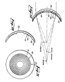
- a movable mirror 27 and a stationary mirror 28 are positioned as shown, both at 45° to the optical axis 10. The movable mirror thus deflects the optical axis 90° onto the stationary mirror, which in turn deflects the optical axis 90° onto the Fresnel zone plate mask 18 and through the optics to the image surface 30.
- the movable mirror 27 is reciprocable from one extreme position 1, through a center position 2, to the other extreme position 3, and back. Through one such stroke, from position 1 to position 3, the output beam 13 scans the Fresnel zone plate mask 18 from bottom (line 1) to top (line 3) as represented on the drawing. Scanning operation, according to the system of Figure 5, enables increased energy concentration at the target for better results.
- the workpiece is a contact lens blank 32
- the finished product of the process is a lens with a phase zone plate generated on its inner surface.
- the system and process are also intended to produce tools from which many molds will be made, and from these molds many more lenses will in turn be made.
- the workpiece is a glass tool blank 50 (Figure 6), having a concave surface 52 to be positioned coincident with the image surface 30 of Figure 1 or Figure 5.
- a positive pattern of the desired phase zone plate is formed and etched on the concave glass surface 52 to produce a glass tool 54 ( Figure 7).
- Plastic molds 56 ( Figure 8) are then made from the glass tool 54, such molds being negatives of the tool 54 and of the desired lens.
- a mold 56 thus formed is then used to replicate the phase zone plate on the concave inner surface 58 of a contact lens 60.
- variable magnification of the optics enables production of a theoretically limitless number of different zone plate profiles, i.e. bifocal additions.
- Figures 10 and 11 show schematically, and substantially enlarged, a contact lens 34 made from a lens blank by the system and process of this invention.
- Lens 34 includes a front surface 35 and a rear surface 36.
- zones 42 are seen to be grooves of uniform depth in the concave lens surface 36.
- the depth of these grooves is calculated from the refractive index difference, which will be present in the lens on the eye at this interface to produce an effective optical path difference of 0.280 microns at each discontinuity. Typically, this physical profile depth will be several microns, but may be tens of microns or more.
- the grooves 42 are preferably on the rear surface 36 of the lens, as shown, so as to be filled with tears while the lens is on the eye. The correct depth for the lens/tear combination depends on lens material, i.e. refractive index, but is typically about 3 microns.
- the grooves shown are, of course, greatly exaggerated; a cross section of the actual contact lens will appear perfectly continuous.
- Another form of the contact lens is a composite lens in which the generated phase zone plate is sandwiched between two lens materials of different refractive index, or within the body of a single lens material.
- the outer surfaces of such a configuration are perfectly smooth and continuous, in fact as well as in appearance, and the zones themselves less conspicuous.
- the optical principle of the lens in this form is the same as that of the lens in Figure 10.
- Figure 12 illustrates the optical action of the contact lens 34.
- the lens 34 with the phase zone plate 40 on its inner surface, is shown on a corneal surface 44.
- Light entering the lens 34 is diffracted by the zone plate 40 away from the normal refractive focus of the lens (indicated as the zero order" image).
- Intra-ocular lenses are lenses implanted in the eye of a patient after cataract surgery to replace the normal crystalline lens. Intra-ocular lenses do not change shape, of course, for distance accomodation, and patients can see clearly at one distance only. An intra-ocular lens with a bifocal addition according to this invention will allow such a patient both near and distance imagery.
- eye lens is used as inclusive of "contact lens” and "intra-ocular lens”.
Abstract
Description
- The subject matter of this invention is contact lenses and intra-ocular lenses, and relates more particularly to a diffractive bifocal contact or intra-ocular lens and to a method of its manufacture by excimer laser ablation. In this specification, it will be convenient to use a single term to mean both "contact lens" and "intra-ocular lens". The term "eye lens" is hereby coined for this purpose.
- The adaptation of a phase zone plate for use as a diffractive bifocal contact lens was apparently first reported in 1966 by G. Forst in Der Augenoptiker. The lens was made by drawing the desired zone pattern on paper, producing a photographic negative of this pattern, projecting an image of the negative on an emulsion surface on the corneal bowl, and developing the photo-emulsion. The Forst paper concludes that the feasibility of a diffractive bifocal contact lens, for special cases, is demonstrated. The fabrication of such a lens accurately, reproducibly, and in acceptable wearable form, has however remained a problem until the present.
- United States Patent No. 4,642,112 was issued on February 10, 1987 to Michael H. Freeman. It discloses a contact lens having the appropriate curvatures providing basic refractive power for ordinary or distance vision: with a transmission hologram formed on the lens to provide diffractive power which is additive to the refractive power for near vision.
- Generally, the etching of polymers by excimer lasers has been widely reported in the literature. Specifically, the production of diffraction gratings by laser etching of photo resists is also well known to the art.
- Finally, European Patent Application No. 0,264,255 was published on April 20, 1988 and discloses an excimer laser optical system for cutting and shaping contact lenses and like objects.
- This invention includes a diffractive bifocal eye lens, and a unique optical system and processes for fast, accurate and reproducible fabrication of a such lenses. The optical system includes the following principal elements in optical alignment along an optical axis, for accomplishing the indicated steps of the process: a laser for emission of ultraviolet light along the optical axis: a zone plate mask in the path of irradiation by the laser; and an imaging lens to project, with radiation from the laser, an image of the mask on the concave inner surface of an eye lens mounted coincident with the image surface of the optical system, thereby ablating the eye lens imagewise of the mask to generate a phase zone plate on the eye lens. The laser beam scans the zone plate mask to generate a composite image on the image surface.
- In an alternative method, the phase zone plate is generated on the concave surface of a glass blank at the image surface to form a tool from which molds, and in turn lenses, are replicated.
- The preferred light source is an argon fluoride excimer laser, emitting at 193 nm. The preferred lens is a variable magnification lens to project various size images of the mask for producing zone plates of various powers as desired.
-
- Figure 1 is an optical diagram of a system according to this invention.
- Figure 2 is a partial diagram of the optical system at one magnification.
- Figure 3 is a partial diagram of the system at another magnification.
- Figure 4 is an enlarged axial view of a zone plate mask from Figure 1.
- Figure 5 is an optical diagram of a modification of the system of Figure 1.
- Figures 6-9 represent a sequence of steps in making lenses according to a modified system and process of this invention.
- Figure 10 is an enlarged schematic cross section of a contact lens made according to this invention.
- Figure 11 is an axial view of the lens, as from the left of Figure 6.
- Figure 12 is an optical schematic of the lens in use, showing ray traces of interest.
- In Figure 1, an optical system according to this invention is shown in optical alignment along an
optical axis 10. The system includes an ultraviolet laser 12, a beam profiler 14, a Fresnelzone plate mask 18, and animaging lens system 20, all directed at animage surface 30 which is coincident with the concave inner surface of an eye lens or lens blank 32. - The ultra
violet laser 12 is preferably an excimer laser, more specifically an Argon Fluoride laser, emitting at 193 nm, and capable of producing a sufficiently large output beam at intensities of from 100 to 600 mJ/cm². The output oflaser 12 is a beam 13 of rectangular cross section. - The beam profiler 14 may include a negative cylindrical lens 15 to expand the rectangular output beam 13 in the direction shown in Figure 1, and a positive
cylindrical lens 16 to recollimate light from lens 15, thus to provide a profiled beam 17 of more uniform symmetrical intensity than the laser output beam 13. The profiled beam 17 traverses thezone plate mask 18. Theimaging lens system 20 projects a reduced image of the pattern ofmask 18 on theimage surface 30. - The zone plate mask 18 (see also Figure 4) may be simply a metal mask, apertured in accordance with the desired zone plate pattern. Peferably, the
zone plate mask 18 is formed on a substrate, coated with metal and photographically etched with alternate transparent and opaque annular rings in accordance with the desired zone plate pattern. A fused silica plate is preferred as the substrate because it is transmissive of ultraviolet light. Aluminum is the preferred coating metal because it reflects efficiently at the ultraviolet wavelengths of excimer lasers. A thin layer of chromium may be used between the substrate and the metal coating to improve adhesion. The entire surface may be coated with magnesium fluoride to protect the metal from oxidation and to reduce reflection losses from the substrate. - In its simplest form, the
imaging lens 20 may be a single lens of fixed magnification. Preferably, however,lens system 20 is a variable magnification or zoom lens system, providing a variable reduction of the mask image at theimage surface 30, and consequently various diffractive powers of the phase zone plate generated at theimage surface 30. As an example,zoom lens system 20 includeslens elements - Figures 2 and 3 are partial diagrams of the optical system, each at a different magnification. The
lens system 20 in Figure 2 may be set at a magnification of 2.63 X. Thesame lens system 20 in Figure 3 may be at a magnification of 3.03 X. These are, of course, only exemplary figures. It is intended that thezoom lens system 20 will be used at many different magnifications within its useful range. The focal point oflens system 20 is represented at 24. - As shown in Figures 1, 2, and 3, the
zone plate mask 18, which is the object of this optical system, is flat. Itsimage surface 30 is curved. This is purposeful. Thelens system 20 is designed to provide this curvature of field, comparable to the inner curvature of a contact lens blank. The contact lens blank 32 is positioned so that its concave inner surface coincides with thecurved image surface 30. A sharp image of the flatzone plate mask 18 is thus formed on the concave lens blank 32, coinciding as it does with theimage surface 30. - Another requirement and purpose of the optical system is to prevent ionization of air at the system focal point. If the
lens system 20 were such that incident parallel light were brought to an infinitesimal point focus at the lensfocal point 24, resulting local ionization of air at the focal point may have undesirable effects on the operation of the system, the quality of the image formed, and so on. This is avoided by deliberately providing spherical aberration in the lens design. The practical focal point of the lens system is thus not infinitesimal. - Operation of the system is as follows. The image of the
zone plate mask 18 is projected on the concave inner surface of a contact lens blank 32 at theimage surface 30, ablating or etching that surface imagewise of themask 18. The process is carried out in a number of pulses of the laser, as many as ten for example, rather than in a single discharge. The desired total depth of etch is about 3 microns, the exact depth depending on the refractive index of the lens material. The depth of etch per pulse of the laser is typically less than 1 micron. By controlling the number of pulses, the depth of etch can be very closely controlled to produce the desired constant optical path difference of one half wavelength across each boundary of each zone of the phase zone plate generated on the lens blank. This operation provides a non-contact optical means, rather than mechanical cutting, to generate a phase zone plate on a contact lens. - Figure 1 represents the basics of the system of this invention. A preferred modification of this basic system is represented in Figure 5. The system of Figure 5 has much in common with that of Figure 1, and common elements are similarly numbered. As in Figure 1, the output beam 13 is a rectangular strip of light in cross section. Instead of a beam profiler 14 as in Figure 1 to give the beam more area, the rectangular output beam 13 is caused to scan the Fresnel
zone plate mask 18. A movable mirror 27 and astationary mirror 28 are positioned as shown, both at 45° to theoptical axis 10. The movable mirror thus deflects the optical axis 90° onto the stationary mirror, which in turn deflects the optical axis 90° onto the Fresnelzone plate mask 18 and through the optics to theimage surface 30. The movable mirror 27 is reciprocable from oneextreme position 1, through a center position 2, to the other extreme position 3, and back. Through one such stroke, fromposition 1 to position 3, the output beam 13 scans the Fresnelzone plate mask 18 from bottom (line 1) to top (line 3) as represented on the drawing. Scanning operation, according to the system of Figure 5, enables increased energy concentration at the target for better results. - In the system thus far described, the workpiece is a
contact lens blank 32, and the finished product of the process is a lens with a phase zone plate generated on its inner surface. The system and process are also intended to produce tools from which many molds will be made, and from these molds many more lenses will in turn be made. - Reference is now to Figures 6-9, representing a sequence of steps in making tools, molds, and lenses. In this mode, the workpiece is a glass tool blank 50 (Figure 6), having a
concave surface 52 to be positioned coincident with theimage surface 30 of Figure 1 or Figure 5. A positive pattern of the desired phase zone plate is formed and etched on theconcave glass surface 52 to produce a glass tool 54 (Figure 7). Plastic molds 56 (Figure 8) are then made from the glass tool 54, such molds being negatives of the tool 54 and of the desired lens. Amold 56 thus formed is then used to replicate the phase zone plate on the concaveinner surface 58 of acontact lens 60. - Whether the system and process are used to make lenses directly, or to make tools from which molds and then lenses are in turn made, the variable magnification of the optics enables production of a theoretically limitless number of different zone plate profiles, i.e. bifocal additions.
- Figures 10 and 11 show schematically, and substantially enlarged, a
contact lens 34 made from a lens blank by the system and process of this invention.Lens 34 includes afront surface 35 and arear surface 36. Aphase zone plate 40 is made up of a number ofconcentric phase zones surface 36 of the lens. The several zones are of equal area, their radii being related according to the series: R₁ = 1; R₂ = R₁√2; R₃ = R₁√3; R₄ = R₁√4; and so on. In Figure 10,zones 42 are seen to be grooves of uniform depth in theconcave lens surface 36. The depth of these grooves is calculated from the refractive index difference, which will be present in the lens on the eye at this interface to produce an effective optical path difference of 0.280 microns at each discontinuity. Typically, this physical profile depth will be several microns, but may be tens of microns or more. Thegrooves 42 are preferably on therear surface 36 of the lens, as shown, so as to be filled with tears while the lens is on the eye. The correct depth for the lens/tear combination depends on lens material, i.e. refractive index, but is typically about 3 microns. The grooves shown are, of course, greatly exaggerated; a cross section of the actual contact lens will appear perfectly continuous. - Another form of the contact lens is a composite lens in which the generated phase zone plate is sandwiched between two lens materials of different refractive index, or within the body of a single lens material. The outer surfaces of such a configuration are perfectly smooth and continuous, in fact as well as in appearance, and the zones themselves less conspicuous. The optical principle of the lens in this form is the same as that of the lens in Figure 10.
- Figure 12 illustrates the optical action of the
contact lens 34. Thelens 34, with thephase zone plate 40 on its inner surface, is shown on a corneal surface 44. There is a film oftear fluid 45 between the cornea 44 and the lens inner surface. Light entering thelens 34 is diffracted by thezone plate 40 away from the normal refractive focus of the lens (indicated as the zero order" image). - At the design wavelength, and with a perfect profile, theory predicts that complete destructive interference occurs at the zero order and at all even orders if the phase shift is exactly half of the design wavelength at each discontinuity. At the odd orders, theory predicts that about 41% of the input light is expected in the +1 order and 41% in the -1 order, with less than 5% occurring in any higher order. Errors in the profile depth within 20% will alter the intensity of light in each order only slightly. The lens performance will therefore be very tolerant of production variability with respect to profile depth.
- The system and process have so far been described and illustrated with reference to contact lenses and contact lens manufacture. The invention is also intended for the manufacture of intra-ocular lenses. Intra-ocular lenses are lenses implanted in the eye of a patient after cataract surgery to replace the normal crystalline lens. Intra-ocular lenses do not change shape, of course, for distance accomodation, and patients can see clearly at one distance only. An intra-ocular lens with a bifocal addition according to this invention will allow such a patient both near and distance imagery.
- The foregoing description of this invention is intended as illustrative. The concept and scope of the invention are limited only by the following claims and equivalents thereof.
- In the following claims, as in the specification, the term "eye lens" is used as inclusive of "contact lens" and "intra-ocular lens".
Claims (20)
a laser for emission of ultraviolet light along said optical axis;
a zone plate mask disposed for irradiation by said laser; and
an imaging lens to project an image of said mask on a concave curved image surface coincident with the inner concave surface of an eye lens.
a laser for emission of ultraviolet light along said optical axis;
a zone plate mask disposed for irradiation by said laser; and
an imaging lens to project an image of said mask on a concave curved image surface coincident with a concave surface of said tool.
Applications Claiming Priority (2)
| Application Number | Priority Date | Filing Date | Title |
|---|---|---|---|
| US07/271,826 US4909818A (en) | 1988-11-16 | 1988-11-16 | System and process for making diffractive contact |
| US271826 | 1988-11-16 |
Publications (2)
| Publication Number | Publication Date |
|---|---|
| EP0369561A2 true EP0369561A2 (en) | 1990-05-23 |
| EP0369561A3 EP0369561A3 (en) | 1991-11-06 |
Family
ID=23037253
Family Applications (1)
| Application Number | Title | Priority Date | Filing Date |
|---|---|---|---|
| EP19890250086 Ceased EP0369561A3 (en) | 1988-11-16 | 1989-11-14 | System and process for making diffractive contact lenses and diffractive intra-ocular lenses |
Country Status (4)
| Country | Link |
|---|---|
| US (1) | US4909818A (en) |
| EP (1) | EP0369561A3 (en) |
| JP (1) | JPH02249631A (en) |
| CA (1) | CA2002394A1 (en) |
Cited By (17)
| Publication number | Priority date | Publication date | Assignee | Title |
|---|---|---|---|---|
| DE4110614A1 (en) * | 1991-04-02 | 1992-10-08 | Rupp & Hubrach Kg | Rugged lens e.g. for spectacles - has main body with diffractive focussing features on side covered with protective e.g. polysiloxane coating of lower refractive index |
| DE4134518A1 (en) * | 1991-10-18 | 1993-04-22 | Adatomed Pharma & Med | OPHTHALMIC LENS |
| FR2686427A1 (en) * | 1992-01-20 | 1993-07-23 | Essilor Int | Optical combination and exposure device employing such a combination |
| WO1998031299A3 (en) * | 1997-01-21 | 1998-11-12 | Technomed Ges Fuer Med Und Med | Method for producing a synthetic eye lens |
| WO2003107076A1 (en) * | 2002-06-14 | 2003-12-24 | 株式会社メニコン | Lens for eye |
| US7365917B2 (en) | 2004-08-16 | 2008-04-29 | Xceed Imaging Ltd. | Optical method and system for extended depth of focus |
| EP2302421A1 (en) | 2004-08-16 | 2011-03-30 | Xceed Imaging Ltd. | System for extending the depth of focus |
| US8169716B2 (en) | 2010-02-09 | 2012-05-01 | Xceed Imaging, Ltd. | Optical apparatus with structure for liquid invariant performance |
| WO2014161639A1 (en) * | 2013-04-02 | 2014-10-09 | Rodenstock Gmbh | Creation of microstructured spectacle lenses in prescription lens production |
| US9091865B2 (en) | 2012-01-18 | 2015-07-28 | Johnson & Johnson Vision Care, Inc. | Fractal features for enhanced tear exchange |
| US11022815B2 (en) | 2012-08-31 | 2021-06-01 | Amo Groningen B.V. | Multi-ring lens, systems and methods for extended depth of focus |
| US11156853B2 (en) | 2017-06-28 | 2021-10-26 | Amo Groningen B.V. | Extended range and related intraocular lenses for presbyopia treatment |
| US11262598B2 (en) | 2017-06-28 | 2022-03-01 | Amo Groningen, B.V. | Diffractive lenses and related intraocular lenses for presbyopia treatment |
| US11327210B2 (en) | 2017-06-30 | 2022-05-10 | Amo Groningen B.V. | Non-repeating echelettes and related intraocular lenses for presbyopia treatment |
| US11497599B2 (en) | 2017-03-17 | 2022-11-15 | Amo Groningen B.V. | Diffractive intraocular lenses for extended range of vision |
| US11523897B2 (en) | 2017-06-23 | 2022-12-13 | Amo Groningen B.V. | Intraocular lenses for presbyopia treatment |
| US11844689B2 (en) | 2019-12-30 | 2023-12-19 | Amo Groningen B.V. | Achromatic lenses and lenses having diffractive profiles with irregular width for vision treatment |
Families Citing this family (34)
| Publication number | Priority date | Publication date | Assignee | Title |
|---|---|---|---|---|
| JPH02137681A (en) * | 1988-11-15 | 1990-05-25 | Matsushita Electric Ind Co Ltd | Manufacture of film capacitor |
| US5091626A (en) * | 1990-02-02 | 1992-02-25 | Hadassah Medical Organization | Method for the ablative reshaping of material surfaces |
| US5170191A (en) * | 1990-05-18 | 1992-12-08 | Bausch & Lomb Incorporated | Target domain profiling of target optical surfaces using excimer laser photoablation |
| US5240553A (en) * | 1990-05-18 | 1993-08-31 | Bausch & Lomb Incorporated | One and two dimensional target domain profiling of target optical surfaces using excimer laser photoablation |
| US5061342A (en) * | 1990-05-18 | 1991-10-29 | Bausch & Lomb Incorporated | Target domain profiling of target optical surfaces using excimer laser photoablation |
| US5633735A (en) * | 1990-11-09 | 1997-05-27 | Litel Instruments | Use of fresnel zone plates for material processing |
| US5362940A (en) * | 1990-11-09 | 1994-11-08 | Litel Instruments | Use of Fresnel zone plates for material processing |
| WO1994007639A1 (en) * | 1992-09-29 | 1994-04-14 | Bausch & Lomb Incorporated | Symmetric scanning technique for laser ablation |
| US5378582A (en) * | 1992-09-29 | 1995-01-03 | Bausch & Lomb Incorporated | Symmetric sweep scanning technique for laser ablation |
| GB9301614D0 (en) * | 1993-01-27 | 1993-03-17 | Pilkington Diffractive Lenses | Multifocal contact lens |
| US5748282A (en) * | 1993-01-27 | 1998-05-05 | Pilkington Barnes Hind, Inc. | Multifocal contact lens |
| US5481407A (en) * | 1993-09-14 | 1996-01-02 | Litel Instruments | Apparatus and process for using Fresnel zone plate array for processing materials |
| US5571429A (en) * | 1994-02-25 | 1996-11-05 | Litel Instruments | Apparatus and process for high speed laminate processing with computer generated holograms |
| EP0822881B1 (en) | 1995-04-26 | 2009-08-12 | Minnesota Mining And Manufacturing Company | Laser imaging ablation method |
| US7063422B2 (en) * | 2003-04-16 | 2006-06-20 | Novartis Ag | Multifocal ophthalmic lens |
| US6896368B2 (en) * | 2003-05-07 | 2005-05-24 | Thomas K. Baugh | Multifocal soft contact lens with horizontally decentered lenslet and indicator marking |
| WO2005005121A2 (en) * | 2003-07-11 | 2005-01-20 | Koninklijke Philips Electronics N.V. | A method of manufacturing a mould for producing an optical surface, a method of producing a contact lens and a device for use with these methods |
| EP2527908B1 (en) * | 2004-10-25 | 2019-03-20 | Johnson & Johnson Surgical Vision, Inc. | Ophthalmic lens with multiple phase plates |
| US7922326B2 (en) | 2005-10-25 | 2011-04-12 | Abbott Medical Optics Inc. | Ophthalmic lens with multiple phase plates |
| FR2902530A1 (en) * | 2006-06-19 | 2007-12-21 | St Microelectronics Rousset | Polymer lens fabricating method for e.g. complementary MOS imager, involves realizing opaque zones on convex lens by degrading molecular structure of polymer material, where zones form diaphragm and diffraction network that forms filter |
| US20080004698A1 (en) * | 2006-06-30 | 2008-01-03 | Alcon, Inc. | Correction of surgically-induced astigmatism during intraocular lens implants |
| AR062067A1 (en) * | 2006-07-17 | 2008-10-15 | Novartis Ag | TORICAS CONTACT LENSES WITH CONTROLLED OPTICAL POWER PROFILE |
| FR2918557B1 (en) * | 2007-07-09 | 2009-10-02 | Gilbert Cohen | INTRACORNEAN DIFFRACTIVE LENS. |
| JP5785093B2 (en) * | 2008-11-20 | 2015-09-24 | アルコン,インコーポレイティド | Diffractive multifocal intraocular lens with altered center distance zone |
| ES2732434T3 (en) | 2008-12-22 | 2019-11-22 | Medical College Of Wisconsin Inc | Apparatus for limiting the growth of eye length |
| US10029331B2 (en) * | 2009-09-14 | 2018-07-24 | Preco, Inc. | Multiple laser beam focusing head |
| US9636050B1 (en) | 2013-11-07 | 2017-05-02 | Verily Life Sciences Llc | Methods and apparatus for forming a channel through a polymer layer using a protrusion |
| US10232531B1 (en) | 2014-07-08 | 2019-03-19 | Verily Life Sciences Llc | Methods and apparatus for forming a polymer layer around a structure using a plurality of protrusions |
| US9907498B2 (en) | 2014-09-04 | 2018-03-06 | Verily Life Sciences Llc | Channel formation |
| AU2017218681B2 (en) | 2016-02-09 | 2021-09-23 | Amo Groningen B.V. | Progressive power intraocular lens, and methods of use and manufacture |
| CN109716212B (en) | 2016-08-01 | 2022-08-12 | 华盛顿大学 | Ophthalmic lens for the treatment of myopia |
| TWI685692B (en) * | 2017-05-08 | 2020-02-21 | 美商賽特眼鏡視光有限公司 | Contact lenses for reducing myopia and methods for making the same |
| US10884264B2 (en) | 2018-01-30 | 2021-01-05 | Sightglass Vision, Inc. | Ophthalmic lenses with light scattering for treating myopia |
| WO2023111280A1 (en) * | 2021-12-17 | 2023-06-22 | Essilor International | Optical lens element for slowing down evolution of abnormal visual refraction |
Citations (3)
| Publication number | Priority date | Publication date | Assignee | Title |
|---|---|---|---|---|
| EP0064812A2 (en) * | 1981-04-29 | 1982-11-17 | Pilkington P.E. Limited | Artificial eye lenses |
| EP0264255A1 (en) * | 1986-10-14 | 1988-04-20 | Allergan, Inc | Manufacture of ophthalmic lenses by excimer laser |
| EP0271002A2 (en) * | 1986-12-06 | 1988-06-15 | Kuraray Co., Ltd. | Transmittance modulation photomask, process for producing the same and process for producing diffraction grating |
Family Cites Families (5)
| Publication number | Priority date | Publication date | Assignee | Title |
|---|---|---|---|---|
| JPS582034A (en) * | 1981-06-29 | 1983-01-07 | Toshiba Corp | Manufacture of semiconductor device |
| DE3381691D1 (en) * | 1982-10-13 | 1990-08-02 | Ng Trustees & Nominees Ltd | BIFOCAL CONTACT LENSES. |
| US4563565A (en) * | 1983-03-02 | 1986-01-07 | Minnesota Mining And Manufacturing Company | Method for forming a peripheral edge on contact lenses |
| US4675072A (en) * | 1986-06-25 | 1987-06-23 | International Business Machines Corporation | Trench etch endpoint detection by LIF |
| LU86722A1 (en) * | 1986-12-23 | 1988-07-14 | Glaverbel | SHEET OF GLASS MATERIAL CARRYING A SERIOUS DRAWING AND METHOD FOR ENGRAVING A DRAWING ON A SUBSTRATE OF GLASS MATERIAL |
-
1988
- 1988-11-16 US US07/271,826 patent/US4909818A/en not_active Expired - Lifetime
-
1989
- 1989-11-07 CA CA002002394A patent/CA2002394A1/en not_active Abandoned
- 1989-11-14 EP EP19890250086 patent/EP0369561A3/en not_active Ceased
- 1989-11-15 JP JP1295146A patent/JPH02249631A/en active Pending
Patent Citations (3)
| Publication number | Priority date | Publication date | Assignee | Title |
|---|---|---|---|---|
| EP0064812A2 (en) * | 1981-04-29 | 1982-11-17 | Pilkington P.E. Limited | Artificial eye lenses |
| EP0264255A1 (en) * | 1986-10-14 | 1988-04-20 | Allergan, Inc | Manufacture of ophthalmic lenses by excimer laser |
| EP0271002A2 (en) * | 1986-12-06 | 1988-06-15 | Kuraray Co., Ltd. | Transmittance modulation photomask, process for producing the same and process for producing diffraction grating |
Cited By (38)
| Publication number | Priority date | Publication date | Assignee | Title |
|---|---|---|---|---|
| DE4110614A1 (en) * | 1991-04-02 | 1992-10-08 | Rupp & Hubrach Kg | Rugged lens e.g. for spectacles - has main body with diffractive focussing features on side covered with protective e.g. polysiloxane coating of lower refractive index |
| DE4134518A1 (en) * | 1991-10-18 | 1993-04-22 | Adatomed Pharma & Med | OPHTHALMIC LENS |
| FR2686427A1 (en) * | 1992-01-20 | 1993-07-23 | Essilor Int | Optical combination and exposure device employing such a combination |
| US5347398A (en) * | 1992-01-20 | 1994-09-13 | Essilor International Cie Generale D'optique | Optical system for forming an image of a plane on a spherical surface |
| WO1998031299A3 (en) * | 1997-01-21 | 1998-11-12 | Technomed Ges Fuer Med Und Med | Method for producing a synthetic eye lens |
| US6215096B1 (en) | 1997-01-21 | 2001-04-10 | TECHNOMED GESELLSCHAFT FüR MED. UND MED.-TECHN. SYSTEME MBH | Method for determining a required shape for at least one surface of an artificial or natural part of an eye which is intersected by a path of rays through the pupil of the eye, and device for the manufacture of an artificial lens |
| WO2003107076A1 (en) * | 2002-06-14 | 2003-12-24 | 株式会社メニコン | Lens for eye |
| US7365917B2 (en) | 2004-08-16 | 2008-04-29 | Xceed Imaging Ltd. | Optical method and system for extended depth of focus |
| US7859769B2 (en) | 2004-08-16 | 2010-12-28 | Xceed Imaging Ltd. | Optical method and system for extended depth of focus |
| EP2302421A1 (en) | 2004-08-16 | 2011-03-30 | Xceed Imaging Ltd. | System for extending the depth of focus |
| EP3364220A1 (en) | 2004-08-16 | 2018-08-22 | Brien Holden Vision Institute | Method and system for extending the depth of focus |
| US8192022B2 (en) | 2004-08-16 | 2012-06-05 | Xceed Imaging Ltd. | Optical method and system for extended depth of focus |
| US9239471B2 (en) | 2010-02-09 | 2016-01-19 | Brien Holden Vision Institute | Multi-focal lens |
| US8169716B2 (en) | 2010-02-09 | 2012-05-01 | Xceed Imaging, Ltd. | Optical apparatus with structure for liquid invariant performance |
| US8913331B2 (en) | 2010-02-09 | 2014-12-16 | Brien Holden Vision Institute | Imaging method and system with optimized extended depth of focus |
| US8955968B2 (en) | 2010-02-09 | 2015-02-17 | Brien Holden Vision Institute | Imaging with extended depth of focus for use with polychromatic light |
| US11802998B2 (en) | 2010-02-09 | 2023-10-31 | Brien Holden Vision Institute Limited | Imaging system with optimized extended depth of focus |
| US9134543B2 (en) | 2010-02-09 | 2015-09-15 | Brien Holden Vision Institute | Imaging system with optimized extended depth of focus |
| US8531783B2 (en) | 2010-02-09 | 2013-09-10 | Xceed Imaging Ltd. | Imaging method and system for imaging with extended depth of focus |
| US9429768B2 (en) | 2010-02-09 | 2016-08-30 | Brien Holden Vision Institute | Imaging method and system with optimized extended depth of focus |
| US9500875B2 (en) | 2010-02-09 | 2016-11-22 | Brien Holden Vision Institute | Imaging with extended depth of focus for use with polycromatic light |
| US10031334B2 (en) | 2010-02-09 | 2018-07-24 | Brien Holden Vision Institute | Optical apparatus with structure for liquid invariant performance |
| US11199651B2 (en) | 2010-02-09 | 2021-12-14 | Brien Holden Vision Institute Limited | Imaging system with optimized extended depth of focus |
| US10078159B2 (en) | 2010-02-09 | 2018-09-18 | Brien Holden Vision Institute | Multi-focal lens |
| US10175392B2 (en) | 2010-02-09 | 2019-01-08 | Brien Holden Vision Institute | Imaging system with optimized extended depth of focus |
| US11802997B2 (en) | 2010-02-09 | 2023-10-31 | Brien Holden Vision Institute Limited | Optical apparatus with structure for liquid invariant performance |
| US11079517B2 (en) | 2010-02-09 | 2021-08-03 | Brien Holden Vision Institute Limited | Optical apparatus with structure for liquid invariant performance |
| US9091865B2 (en) | 2012-01-18 | 2015-07-28 | Johnson & Johnson Vision Care, Inc. | Fractal features for enhanced tear exchange |
| US11022815B2 (en) | 2012-08-31 | 2021-06-01 | Amo Groningen B.V. | Multi-ring lens, systems and methods for extended depth of focus |
| WO2014161639A1 (en) * | 2013-04-02 | 2014-10-09 | Rodenstock Gmbh | Creation of microstructured spectacle lenses in prescription lens production |
| US11497599B2 (en) | 2017-03-17 | 2022-11-15 | Amo Groningen B.V. | Diffractive intraocular lenses for extended range of vision |
| US11523897B2 (en) | 2017-06-23 | 2022-12-13 | Amo Groningen B.V. | Intraocular lenses for presbyopia treatment |
| US11262598B2 (en) | 2017-06-28 | 2022-03-01 | Amo Groningen, B.V. | Diffractive lenses and related intraocular lenses for presbyopia treatment |
| US11573433B2 (en) | 2017-06-28 | 2023-02-07 | Amo Groningen B.V. | Extended range and related intraocular lenses for presbyopia treatment |
| US11156853B2 (en) | 2017-06-28 | 2021-10-26 | Amo Groningen B.V. | Extended range and related intraocular lenses for presbyopia treatment |
| US11914229B2 (en) | 2017-06-28 | 2024-02-27 | Amo Groningen B.V. | Diffractive lenses and related intraocular lenses for presbyopia treatment |
| US11327210B2 (en) | 2017-06-30 | 2022-05-10 | Amo Groningen B.V. | Non-repeating echelettes and related intraocular lenses for presbyopia treatment |
| US11844689B2 (en) | 2019-12-30 | 2023-12-19 | Amo Groningen B.V. | Achromatic lenses and lenses having diffractive profiles with irregular width for vision treatment |
Also Published As
| Publication number | Publication date |
|---|---|
| CA2002394A1 (en) | 1990-05-16 |
| US4909818A (en) | 1990-03-20 |
| JPH02249631A (en) | 1990-10-05 |
| EP0369561A3 (en) | 1991-11-06 |
Similar Documents
| Publication | Publication Date | Title |
|---|---|---|
| US4909818A (en) | System and process for making diffractive contact | |
| AU629028B2 (en) | Manufacture of ophthalmic lenses by excimer laser | |
| JP2755610B2 (en) | Method for making a mark and / or mark on spectacle lens and spectacle lens manufactured by the method | |
| US5344447A (en) | Diffractive trifocal intra-ocular lens design | |
| EP1779152B1 (en) | Method and system for extending the depth of focus | |
| KR101285056B1 (en) | Lighting optical device, exposure system and exposure method | |
| TW583720B (en) | Optical illuminating system, light exposure equipment and manufacturing method of micro-devices | |
| JP2006502443A (en) | Apparatus and method for making correction elements for wavefront correction utilizing spatially localized resin mixture curing | |
| WO1995010827A2 (en) | Retroreflective sheeting material, a method of its production and its use | |
| US6259567B1 (en) | Microlens structure having two anamorphic surfaces on opposing ends of a single high index substances and method of fabricating the same | |
| Kley et al. | Fabrication of micro-optical surface profiles by using grayscale masks | |
| JP2004310077A (en) | Method for manufacturing microlens, microlens and exposure device | |
| US5179262A (en) | Manufacture of ophthalmic lenses by excimer laser | |
| US5061840A (en) | Manufacture of ophthalmic lenses by excimer laser | |
| CN113031252A (en) | Micro mirror with micro-nano structure, micro mirror manufacturing method and laser display system | |
| EP1548804B1 (en) | Illuminating optical system, exposure system and exposure method | |
| JPH0373954A (en) | Method of manufacturing product having structure with numerous thin lines | |
| JP2005157358A (en) | Refractivity/diffractive hybrid type lens for beam shaping specially for high output diode laser | |
| JP5414945B1 (en) | Optical element and imaging apparatus including the same | |
| JP2006215131A (en) | Aspheric lens, cylindrical lens, aspheric reflecting mirror, cylindrical reflecting mirror, micro fly-eye optical element, and exposure apparatus | |
| JPH11314184A (en) | Optical device machining apparatus | |
| EP4335630A1 (en) | Method for patterning a mask, method for producing an insert or a mold, and optical article with surface microstructures | |
| JPH11109117A (en) | Manufacture of diffraction optical element and manufacturing device therefor | |
| JP2002202583A (en) | Method for producing mask, method for producing optical element using the same, method for producing optical element, method for producing exposure system using optical element produced by this method and method for producing aberration measuring device | |
| JPH1152114A (en) | Production of element having fine rugged patterns |
Legal Events
| Date | Code | Title | Description |
|---|---|---|---|
| PUAI | Public reference made under article 153(3) epc to a published international application that has entered the european phase |
Free format text: ORIGINAL CODE: 0009012 |
|
| AK | Designated contracting states |
Kind code of ref document: A2 Designated state(s): AT BE CH DE ES FR GB IT LI NL SE |
|
| PUAL | Search report despatched |
Free format text: ORIGINAL CODE: 0009013 |
|
| AK | Designated contracting states |
Kind code of ref document: A3 Designated state(s): AT BE CH DE ES FR GB IT LI NL SE |
|
| 17P | Request for examination filed |
Effective date: 19920222 |
|
| 17Q | First examination report despatched |
Effective date: 19931006 |
|
| STAA | Information on the status of an ep patent application or granted ep patent |
Free format text: STATUS: THE APPLICATION HAS BEEN REFUSED |
|
| 18R | Application refused |
Effective date: 19941229 |