EP0368848B1 - Primary pressure-balanced proportioning valve - Google Patents
Primary pressure-balanced proportioning valve Download PDFInfo
- Publication number
- EP0368848B1 EP0368848B1 EP88902291A EP88902291A EP0368848B1 EP 0368848 B1 EP0368848 B1 EP 0368848B1 EP 88902291 A EP88902291 A EP 88902291A EP 88902291 A EP88902291 A EP 88902291A EP 0368848 B1 EP0368848 B1 EP 0368848B1
- Authority
- EP
- European Patent Office
- Prior art keywords
- proportioning valve
- piston
- pressure
- bore
- accordance
- Prior art date
- Legal status (The legal status is an assumption and is not a legal conclusion. Google has not performed a legal analysis and makes no representation as to the accuracy of the status listed.)
- Expired - Lifetime
Links
Images

Classifications
-
- B—PERFORMING OPERATIONS; TRANSPORTING
- B60—VEHICLES IN GENERAL
- B60T—VEHICLE BRAKE CONTROL SYSTEMS OR PARTS THEREOF; BRAKE CONTROL SYSTEMS OR PARTS THEREOF, IN GENERAL; ARRANGEMENT OF BRAKING ELEMENTS ON VEHICLES IN GENERAL; PORTABLE DEVICES FOR PREVENTING UNWANTED MOVEMENT OF VEHICLES; VEHICLE MODIFICATIONS TO FACILITATE COOLING OF BRAKES
- B60T8/00—Arrangements for adjusting wheel-braking force to meet varying vehicular or ground-surface conditions, e.g. limiting or varying distribution of braking force
- B60T8/26—Arrangements for adjusting wheel-braking force to meet varying vehicular or ground-surface conditions, e.g. limiting or varying distribution of braking force characterised by producing differential braking between front and rear wheels
- B60T8/262—Arrangements for adjusting wheel-braking force to meet varying vehicular or ground-surface conditions, e.g. limiting or varying distribution of braking force characterised by producing differential braking between front and rear wheels using valves with stepped characteristics
- B60T8/265—Arrangements for adjusting wheel-braking force to meet varying vehicular or ground-surface conditions, e.g. limiting or varying distribution of braking force characterised by producing differential braking between front and rear wheels using valves with stepped characteristics for hydraulic brake systems
-
- B—PERFORMING OPERATIONS; TRANSPORTING
- B60—VEHICLES IN GENERAL
- B60T—VEHICLE BRAKE CONTROL SYSTEMS OR PARTS THEREOF; BRAKE CONTROL SYSTEMS OR PARTS THEREOF, IN GENERAL; ARRANGEMENT OF BRAKING ELEMENTS ON VEHICLES IN GENERAL; PORTABLE DEVICES FOR PREVENTING UNWANTED MOVEMENT OF VEHICLES; VEHICLE MODIFICATIONS TO FACILITATE COOLING OF BRAKES
- B60T11/00—Transmitting braking action from initiating means to ultimate brake actuator without power assistance or drive or where such assistance or drive is irrelevant
- B60T11/10—Transmitting braking action from initiating means to ultimate brake actuator without power assistance or drive or where such assistance or drive is irrelevant transmitting by fluid means, e.g. hydraulic
- B60T11/16—Master control, e.g. master cylinders
-
- B—PERFORMING OPERATIONS; TRANSPORTING
- B60—VEHICLES IN GENERAL
- B60T—VEHICLE BRAKE CONTROL SYSTEMS OR PARTS THEREOF; BRAKE CONTROL SYSTEMS OR PARTS THEREOF, IN GENERAL; ARRANGEMENT OF BRAKING ELEMENTS ON VEHICLES IN GENERAL; PORTABLE DEVICES FOR PREVENTING UNWANTED MOVEMENT OF VEHICLES; VEHICLE MODIFICATIONS TO FACILITATE COOLING OF BRAKES
- B60T11/00—Transmitting braking action from initiating means to ultimate brake actuator without power assistance or drive or where such assistance or drive is irrelevant
- B60T11/10—Transmitting braking action from initiating means to ultimate brake actuator without power assistance or drive or where such assistance or drive is irrelevant transmitting by fluid means, e.g. hydraulic
- B60T11/28—Valves specially adapted therefor
- B60T11/34—Pressure reducing or limiting valves
Definitions
- the present invention comprises a proportioning valve, the proportioning valve received in a bore having communication means for receiving fluid pressure communicated to the bore, the bore having at one end a first pressure receiving chamber and at the other end a second pressure receiving chamber, the second pressure receiving chamber having an outlet opening, a differential area piston disposed within said bore and having a first end received in the first pressure receiving chamber and a second end received in the second pressure receiving chamber, the first end having a seal thereat to define a part of the first pressure receiving chamber, the second end having sealing means disposed thereat, resilient means biasing said piston, and a stepped, stationary sleeve located in said bore and disposed about said piston in order to define a portion of an intermediate chamber, communication of fluid pressure to the respective pressure receiving chambers causing said differential area piston to be displaced to a substantially balanced position during actuation of said proportioning valve, characterized in that the differential area piston comprises a first piston part and a second piston part, the first piston part having an extension received at a through opening of the second piston part, the extension
Landscapes
- Engineering & Computer Science (AREA)
- Transportation (AREA)
- Mechanical Engineering (AREA)
- Hydraulic Control Valves For Brake Systems (AREA)
- Transmission Of Braking Force In Braking Systems (AREA)
Abstract
Description
- The present invention relates to a proportioning valve utilized in combination with a master cylinder, in particular a proportioning valve whose piston is actuated by fluid pressure received directly from the primary and secondary pressure chambers of the master cylinder.
- In general, proportioning valves utilize a differential area piston in the secondary chamber brake system so that when a predetermined pressure level is reached, the piston shifts in the direction of the smaller area proportioning valve piston end. As the piston shifts, the piston contacts a poppet or seal and thus establishes a pressure restriction. Upon a further increase in secondary pressure communicated to the proportioning valve piston, the outlet pressure will rise at a rate determined by the differential areas at each end of the piston.
- EP-A2-0 163 268 illustrates a proportioning valve which receives pressure from the primary and secondary chambers of the master cylinder so that the piston of the valve is displaced to a substantially balanced position during actuation of the proportioning valve.
- A proportioning valve may be coupled with the master cylinder by means of a threaded connection. The proportioning valve includes a bypass function so that upon failure of pressure in a chamber of the master cylinder, the proportioning valve responds appropriately and permits fluid pressure to be communicated freely to the rear brakes of the vehicle. Such existing designs contain numerous disadvantages such as: the primary and secondary pressure chambers of the master cylinder must be reversed which lengthens the master cylinder body; the master cylinder being stroke sensitive rather than pressure sensitive; the utilization of mechanical actuation instead of hydraulic actuation; numerous parts required for the assembly which results in high cost; and a bypass mechanism that is subject to many manufacturing tolerances and possibly subject to damage. It is highly desirable to provide a proportioning valve assembly with a bypass feature wherein it is not necessary to switch the position of the primary and secondary chambers in the master cylinder. It is also desirable to actuate the proportioning valve assembly by communicating directly pressure from the primary pressure chamber of the master cylinder to the proportioning valve assembly.
- The present invention utilizes a differential area piston with one end of the piston acted upon directly by primary pressure received from the master cylinder. The other, larger diameter, end of the piston is acted upon directly by pressure received from the secondary chamber of the master cylinder. The secondary chamber fluid pressure is proportioned during actuation of the proportioning valve. The large diameter end of the piston is essentially pressure balanced after reaching the break point due to secondary outlet pressure acting on the larger diameter end and the primary pressure acting on the piston's small diameter end. Because the master cylinder primary and secondary pressures on the piston are essentially equal by utilizing the primary pressure to balance the proportioning valve piston, when the primary pressure fails the piston forces become unbalanced and thus shift the piston to a position wherein a bypass circuit is effected so that secondary pressure is communicated freely through the secondary outlet.
- The present invention comprises a proportioning valve, the proportioning valve received in a bore having communication means for receiving fluid pressure communicated to the bore, the bore having at one end a first pressure receiving chamber and at the other end a second pressure receiving chamber, the second pressure receiving chamber having an outlet opening, a differential area piston disposed within said bore and having a first end received in the first pressure receiving chamber and a second end received in the second pressure receiving chamber, the first end having a seal thereat to define a part of the first pressure receiving chamber, the second end having sealing means disposed thereat, resilient means biasing said piston, and a stepped, stationary sleeve located in said bore and disposed about said piston in order to define a portion of an intermediate chamber, communication of fluid pressure to the respective pressure receiving chambers causing said differential area piston to be displaced to a substantially balanced position during actuation of said proportioning valve, characterized in that the differential area piston comprises a first piston part and a second piston part, the first piston part having an extension received at a through opening of the second piston part, the extension having a seal member thereat, the seal member adjacent a second opening in the second piston part and engaging sealingly a part of the second piston part the intermediate chamber comprising a vented intermediate chamber, and failure of pressure in the first pressure receiving chamber displacing the first piston part and seal member to permit fluid to flow through the through opening and effectively bypass the sealing means.
- The invention is described in detail below with reference to the drawings which illustrate embodiments in which:
- Figure 1 is a section view of the proportioning valve and master cylinder of the present invention;
- Figure 2 is a section view of the preferred embodiment;
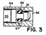
- Figure 3 is an enlarged section view of a portion of Figure 2.
- The master cylinder is designated generally by
reference numeral 10 in Figure 1. The master cylinder is of the type designated "Recessed Cartridge Master Cylinder" and disclosed in U.S. Patent No. 4,474,005. It should be clearly understood that the present invention may be utilized with many other types of master cylinders, and is not restricted to use with just a Recessed Cartridge Master Cylinder. Themaster cylinder 10 includes a primary chamber (not shown) located interiorily of anend 12 and a secondary chamber (not shown) located interiorily of end 14. A passageway or communication means 16 extends from the primary chamber to a primarypressure receiving chamber 26 located within master cylinder housing 11. A passageway or communication means 18 extends between the secondary pressure chamber and a secondarypressure receiving chamber 28 located within housing 11. Avent 19 may extend to either atmosphere or to a reservoir (not shown) of the master cylinder. The proportioning valve assembly is designated generally byreference numeral 40 and comprises avalve housing part 42 received threadably intransverse bore 13 of housing 11.Bore 13 comprises a stepped bore which extends from the primarypressure receiving chamber 26 to the secondarypressure receiving chamber 28.Proportioning valve assembly 40 includes avalve housing part 43 clasped tofirst housing part 42 by means of aflange 44. Steppedbore 13 provides ashoulder 15 for engagement by aseal 46 disposed aboutdifferential area piston 50.Differential area piston 50 includes afirst piston part 52 andsecond piston part 54.First piston part 52 includes anextension 53 received within a through opening 56 ofsecond piston part 54.Extension 53 includes aseal 55 disposed thereabout, the seal blocking fluid flow between aradial opening 57 and through opening 56 insecond piston part 54. Thesecond piston part 54 has aseal 45 disposed thereabout and engaging the interior ofsecond housing part 43. Resilient means 70 extends between asecond housing shoulder 48 and aflange 61 ofsecond piston part 54. Aseal 47 is disposed about the exterior ofsecond housing part 43 and engages ashoulder 17 of housing 11. Thesecond piston part 54 has anend 58 which abutsshoulder 49 ofhousing part 42. Pistonend 58 includes sealing means 72 disposed thereabout. Sealing means 72 has aflexible pumping arm 73,radial passageways 74, and spaced apartcircumferential abutments 75. The interior diameter of resilient sealing means 72 is spaced radially apart from the exterior surface ofcircumferential groove 59 of pistonsecond part 54. Each of the seals disposed about the exterior ofassembly 40 is a static seal which engages a portion ofstepped bore 13 whenvalve assembly 40 is threadably received within housing 11. -
Proportioning valve assembly 40 is shown in an at-rest position. Whenmaster cylinder 10 is actuated by the vehicle operator depressing the brake pedal of the vehicle, primary and secondary chamber fluid pressure is communicated by means ofpassageways pressure receiving chambers differential area piston 50, the secondary pressure displacespiston 50 slightly toward the left in Figure 1, against the force ofresilient means 70 and the primary fluid pressure inchamber 26 acting uponfirst piston part 52. Upon an increase of fluid pressures received inchambers piston 50 is displaced to the left until the outer diameter ofpiston end 58 engages sealing means 72. This causes a restriction or metering of fluid pressure communicated betweenpassageway 18, pressure-receiving chamber 28, andsecondary outlet 21. It should be noted that prior to the leftward movement of thepiston 50, theabutments 75 on sealing means 72 ensures that fluid pressure is free to pass between the interior diameter of sealing means 72 andcircumferential groove 59 to thesecondary outlet 21. As shown in greater detail in Figure 3,seal 55 has a generally L-shaped section and engagesshoulder 51 ofsecond piston part 54.Seal 55 avoids contact withradial opening 57 so that opening 57 cannot cut or gouge out parts ofseal 55. Thus, sealing is accomplished atshoulder 51 so that fluid does not flow through opening 56. Should there be a failure of pressure in the primary chamber ofmaster cylinder 10, an unbalancing of forces is created andfirst piston part 52 moves immediately leftward inchamber 26 which causesextension 53 to moveseal 55 out of sealing engagement withshoulder 51. This permits fluid pressure within secondarypressure receiving chamber 28 to be communicated throughradial opening 57 and through opening 56 tooutlet 21 so that a bypass function is accomplished and full braking pressure may be communicated to the rear brakes of the vehicle. As a result of communicating the master cylinder primary chamber pressure directly to the differential area piston of the proportioning valve assembly, there is no longer required the utilization of primary pressure to indirectly effect a bypass by means of other intermediate mechanisms. The fluid pressure from the primary chamber of the master cylinder acts directly upon the proportioning valve piston to eliminate any need for reversing the primary and secondary chambers of the master cylinder. No external mechanical mechanisms are required in order to actuate the proportioning valve assembly and effect the bypass function. The primary pressure is required for operation of the proportioning valve assembly. However, should there be a failure of fluid pressure in the primary braking circuit, the proportioning valve assembly actuates immediately to effect the bypass feature and permit the direct communication of full fluid pressure tosecondary outlet 21 and the rear brakes of the vehicle. - The proportioning valve assembly and master cylinder of the present invention comprises a substantial improvement over prior constructions. Because the primary chamber fluid pressure is utilized to actuate and operate directly the proportioning valve assembly, intermediate mechanisms and devices and reversal of the pressure chambers of the master cylinder are obviated. An additional advantage is that the proportioning valve assembly and master cylinder permit the communication of greater fluid pressure to the rear brakes of the vehicle when such can be tolerated. In other words, the break point on the pressure curve may be led or lagged according to design modification. In actual operation, the fluid pressures communicated from the primary and secondary chambers of the master cylinder are slightly different, in the magnitude of approximately 20 to 30 psi. The fluid pressure variance communicated from the primary pressure chamber of the master cylinder is approximately 20 to 30 psi. lower than the fluid pressure communicated from the secondary pressure chamber. This is a result of difference in spring loads and seal friction. Thus, during actual braking, the front brakes of the vehicle receive slightly less pressure than the rear brakes of the vehicle receive initially. Therefore, the front brakes are slightly less effective and there is not a shifting of the load off the rear wheels, i.e., the rear portion of the vehicle does not tilt to the extent that it might if the pressures transmitted from the primary and secondary pressure chambers were actually equal. Because of reduced tilting of the vehicle, the rear wheels of the vehicle can tolerate more fluid pressure. In the present invention, the initial slight leftward movement of the differential area piston allows a greater amount of pressure to the rear brakes. This effects a raising of the break-point of the characteristic output pressure curve.
Claims (10)
- A proportioning valve, the proportioning valve (40) received in a bore (13) having communication means (16, 18) for receiving fluid pressure communicated to the bore (13), the bore (13) having at one end a first pressure receiving chamber (26) and at the other end a second pressure receiving chamber (28), the second pressure receiving chamber (28) having an outlet opening (21), a differential area piston (50) disposed within said bore (13) and having a first end received in the first pressure receiving chamber (26) and a second end received in the second pressure receiving chamber (28), the first end having a seal (46) thereat to define a part of the first pressure receiving chamber (26), the second end having sealing means (72) disposed thereat, resilient means (70) biasing said piston (50), and a stepped, stationary sleeve (43) located in said bore (13) and disposed about said piston (50) in order to define a portion of an intermediate chamber (19), communication of fluid pressure to the respective pressure receiving chambers (26, 28) causing said differential area piston (50) to be displaced to a substantially balanced position during actuation of said proportioning valve (40), characterized in that the differential area piston (50) comprises a first piston part (52) and a second piston part (54), the first piston part (52) having an extension (53) received at a through opening (56) of the second piston part (54), the extension (53) having a seal member (55) thereat, the seal member (55) adjacent a second opening (57) in the second piston part (54) and engaging sealingly a part (51) of the second piston part (54), the intermediate chamber comprising a vented (19) intermediate chamber, and failure of pressure in the first pressure receiving chamber (26) displacing the first piston part (52) and seal member (55) to permit fluid to flow through the through opening (56) and effectively bypass the sealing means (72).
- The proportioning valve in accordance with claim 1, characterized in that the bore (13) includes a second seal (47) spaced apart from the seal (46) at the first end to define a portion of the intermediate chamber which communicates with a vent (19).
- The proportioning valve in accordance with claim 2, characterized in that the vent (19) communicates with a reservoir.
- The proportioning valve in accordance with claim 2, characterized in that the intermediate chamber and vent (19) communicate with atmosphere.
- The proportioning valve in accordance with claim 1, characterized in that the sealing means (72) about the second end comprises a flexible arm (73) on one side and a plurality of radial slot (74) openings on the other side, the radial slot (74) openings permitting fluid flow therethrough and past the flexible arm (73) during a release of braking pressure.
- The proportioning valve in accordance with claim 1, characterized in that the resilient means (70) extends between a flange (61) at the second piston part (54) and shoulder means (48) in the bore (13).
- The proportioning valve in accordance with claim 6, characterized in that the proportioning valve (40) includes a housing (42, 43), the housing (42) screwed into the bore (13) which is disposed within a master cylinder (10).
- The proportioning valve in accordance with claim 7, characterized in that the housing (42, 43) comprises two members (42, 43) held together by a flange (44).
- The proportioning valve in accordance with claim 1, characterized in that the intermediate chamber extends interiorly of the sleeve (43).
- The proportioning valve in accordance with claim 9, characterized in that a seal mechanism (45) is disposed between the second piston part (54) and sleeve (43) in order to define a part of the intermediate chamber.
Applications Claiming Priority (2)
| Application Number | Priority Date | Filing Date | Title |
|---|---|---|---|
| US67514 | 1987-06-29 | ||
| US07/067,514 US4821519A (en) | 1987-06-29 | 1987-06-29 | Primary pressure-balanced proportioning valve |
Publications (2)
| Publication Number | Publication Date |
|---|---|
| EP0368848A1 EP0368848A1 (en) | 1990-05-23 |
| EP0368848B1 true EP0368848B1 (en) | 1993-05-26 |
Family
ID=22076492
Family Applications (1)
| Application Number | Title | Priority Date | Filing Date |
|---|---|---|---|
| EP88902291A Expired - Lifetime EP0368848B1 (en) | 1987-06-29 | 1988-02-05 | Primary pressure-balanced proportioning valve |
Country Status (10)
| Country | Link |
|---|---|
| US (1) | US4821519A (en) |
| EP (1) | EP0368848B1 (en) |
| JP (1) | JPH06104443B2 (en) |
| KR (2) | KR920000665B1 (en) |
| AU (1) | AU612941B2 (en) |
| BR (1) | BR8807583A (en) |
| CA (1) | CA1301218C (en) |
| DE (1) | DE3881395T2 (en) |
| ES (1) | ES2009025A6 (en) |
| WO (1) | WO1989000120A1 (en) |
Families Citing this family (6)
| Publication number | Priority date | Publication date | Assignee | Title |
|---|---|---|---|---|
| CA2000771A1 (en) * | 1988-11-03 | 1990-05-03 | Richard Anthony Zander | Primary and secondary pressure-balanced proportioning valve |
| US4908522A (en) * | 1988-11-21 | 1990-03-13 | Allied-Signal Inc. | Pressure-balanced proportioning valve with vent-controlled bypass |
| US5169212A (en) * | 1990-12-21 | 1992-12-08 | Ford Motor Company | Reversible proportioning valve |
| KR100779497B1 (en) * | 2006-09-08 | 2007-11-26 | 주식회사 만도 | Master cylinder |
| KR101921133B1 (en) * | 2016-10-04 | 2018-11-22 | 주식회사 우진더블유티피 | Ceramic reflector of high quality and low cost for crystal growth of oxides and manufacturing method thereof |
| JP6388987B1 (en) * | 2017-08-14 | 2018-09-12 | 伸和コントロールズ株式会社 | Liquid supply device and liquid temperature control system |
Family Cites Families (43)
| Publication number | Priority date | Publication date | Assignee | Title |
|---|---|---|---|---|
| US3423936A (en) * | 1966-03-07 | 1969-01-28 | Kelsey Hayes Co | Pressure proportioning valve |
| US3421321A (en) * | 1966-10-24 | 1969-01-14 | Bendix Corp | Indicating device for dual hydraulic system |
| US3708211A (en) * | 1967-03-28 | 1973-01-02 | Wagner Electric Corp | Control valve system |
| US3480333A (en) * | 1968-03-04 | 1969-11-25 | Kelsey Hayes Co | Brake failure indicator |
| US3463554A (en) * | 1968-08-15 | 1969-08-26 | Wagner Electric Corp | Warning device |
| US3556607A (en) * | 1969-06-11 | 1971-01-19 | Bendix Corp | Combination proportioning and bypass valve |
| US3597014A (en) * | 1969-09-26 | 1971-08-03 | Wagner Electric Corp | Control valve |
| US3597008A (en) * | 1969-10-02 | 1971-08-03 | Wagner Electric Corp | Control valve |
| US3606487A (en) * | 1969-11-04 | 1971-09-20 | Wagner Electric Corp | Control valve |
| US3597015A (en) * | 1970-01-26 | 1971-08-03 | Wagner Electric Corp | Control valve |
| US3712683A (en) * | 1970-03-11 | 1973-01-23 | Weatherhead Co | Brake warning switch |
| US3614169A (en) * | 1970-03-26 | 1971-10-19 | Wagner Electric Corp | Control valve |
| US3672728A (en) * | 1970-04-22 | 1972-06-27 | Weatherhead Co | Combination brake warning switch and proportioning valve |
| JPS4934863B1 (en) * | 1970-08-22 | 1974-09-18 | ||
| US3838887A (en) * | 1970-10-26 | 1974-10-01 | Kelsey Hayes Co | Pressure control device for dual brake system |
| US3717382A (en) * | 1970-11-13 | 1973-02-20 | Kelsey Hayes Co | Device for dual brake systems |
| US3727989A (en) * | 1972-02-16 | 1973-04-17 | Weatherhead Co | Emergency bypass for brake pressure control |
| US3752535A (en) * | 1972-04-17 | 1973-08-14 | Wagner Electric Corp | Control valve and system |
| US3836204A (en) * | 1972-07-17 | 1974-09-17 | Ford Motor Co | Brake system proportioning valve |
| JPS5636101B2 (en) * | 1973-06-29 | 1981-08-21 | ||
| US3832007A (en) * | 1973-07-17 | 1974-08-27 | Weatherhead Co | Blend back proportioning valve |
| JPS5226596B2 (en) * | 1973-11-13 | 1977-07-14 | ||
| US3945686A (en) * | 1973-11-29 | 1976-03-23 | The Weatherhead Company | Blend back proportioning valve |
| JPS5545422B2 (en) * | 1974-04-17 | 1980-11-18 | ||
| US4068901A (en) * | 1974-06-26 | 1978-01-17 | Aisin Seiki Kabushiki Kaisha | Brake pressure difference warning system for vehicles |
| JPS5626581B2 (en) * | 1974-11-15 | 1981-06-19 | ||
| GB1527551A (en) * | 1975-03-13 | 1978-10-04 | Aisin Seiki | Hydraulic braking system control valve |
| US3964795A (en) * | 1975-08-25 | 1976-06-22 | General Motors Corporation | Modular proportioner |
| JPS591618B2 (en) * | 1975-09-17 | 1984-01-13 | トヨタ自動車株式会社 | brake control valve |
| US4058136A (en) * | 1976-10-15 | 1977-11-15 | Wagner Electric Corporation | Pressure distribution valve |
| JPS5442882U (en) * | 1977-08-31 | 1979-03-23 | ||
| US4159755A (en) * | 1977-11-30 | 1979-07-03 | Kang Byung K | Safety hydraulic brake system for automotive vehicles |
| IT1100776B (en) * | 1977-12-03 | 1985-09-28 | Teves Gmbh Alfred | BRAKING PRESSURE CONTROL UNIT |
| JPS54117875A (en) * | 1978-03-03 | 1979-09-12 | Sumitomo Electric Ind Ltd | Follow-up valve |
| US4301653A (en) * | 1979-10-24 | 1981-11-24 | Societe Anonyme D.B.A. | Tandem master cylinder |
| US4272659A (en) * | 1979-12-21 | 1981-06-09 | Dana Corporation | Hydraulic brake warning switch |
| JPS5726029A (en) * | 1980-07-18 | 1982-02-12 | Sumitomo Electric Ind Ltd | Dual system type braking pressure control valve |
| US4490978A (en) * | 1982-08-06 | 1985-01-01 | General Motors Corporation | Fluid pressure proportioners |
| JPS5934545A (en) * | 1982-08-23 | 1984-02-24 | Canon Inc | process kit |
| US4474005A (en) * | 1982-08-26 | 1984-10-02 | The Bendix Corporation | Master cylinder |
| JPS60188059U (en) * | 1984-05-23 | 1985-12-13 | 日産自動車株式会社 | Master cylinder with hydraulic control device |
| US4595243A (en) * | 1984-09-10 | 1986-06-17 | Allied Corporation | Deceleration and pressure sensitive proportioning valve |
| US4673220A (en) * | 1984-10-17 | 1987-06-16 | Sumitomo Electric Industries, Ltd. | Brake pressure control valve assembly having a bypass function |
-
1987
- 1987-06-29 US US07/067,514 patent/US4821519A/en not_active Expired - Fee Related
-
1988
- 1988-02-05 KR KR1019890700381A patent/KR920000665B1/en not_active Expired
- 1988-02-05 DE DE88902291T patent/DE3881395T2/en not_active Expired - Fee Related
- 1988-02-05 AU AU13682/88A patent/AU612941B2/en not_active Ceased
- 1988-02-05 JP JP63502134A patent/JPH06104443B2/en not_active Expired - Lifetime
- 1988-02-05 EP EP88902291A patent/EP0368848B1/en not_active Expired - Lifetime
- 1988-02-05 BR BR888807583A patent/BR8807583A/en not_active IP Right Cessation
- 1988-02-05 WO PCT/US1988/000347 patent/WO1989000120A1/en not_active Ceased
- 1988-03-14 CA CA000561366A patent/CA1301218C/en not_active Expired - Lifetime
- 1988-06-29 ES ES8802037A patent/ES2009025A6/en not_active Expired
-
1989
- 1989-02-28 KR KR1019890700381A patent/KR890701399A/en active Granted
Also Published As
| Publication number | Publication date |
|---|---|
| WO1989000120A1 (en) | 1989-01-12 |
| KR920000665B1 (en) | 1992-01-20 |
| EP0368848A1 (en) | 1990-05-23 |
| US4821519A (en) | 1989-04-18 |
| CA1301218C (en) | 1992-05-19 |
| BR8807583A (en) | 1990-05-08 |
| KR890701399A (en) | 1989-12-20 |
| JPH03500633A (en) | 1991-02-14 |
| AU612941B2 (en) | 1991-07-18 |
| DE3881395D1 (en) | 1993-07-01 |
| JPH06104443B2 (en) | 1994-12-21 |
| DE3881395T2 (en) | 1993-12-16 |
| ES2009025A6 (en) | 1989-08-16 |
| AU1368288A (en) | 1989-01-30 |
Similar Documents
| Publication | Publication Date | Title |
|---|---|---|
| GB2060798A (en) | Hydraulic brake system | |
| US4595243A (en) | Deceleration and pressure sensitive proportioning valve | |
| US4477122A (en) | Hydraulic pressure control valve for automobile braking system | |
| US4821519A (en) | Primary pressure-balanced proportioning valve | |
| EP0402355B1 (en) | Primary pressure-balanced proportioning valve | |
| JPH0241965A (en) | Hydraulic braking device | |
| GB1586516A (en) | Valve arrangement for controlling brake pressure in a vehicular hydraulic braking system | |
| US3637963A (en) | Brake warning switch with bypass | |
| GB2175362A (en) | Anti-skid vehicle braking system | |
| US4736989A (en) | Dual deceleration and pressure-sensitive proportioning valve | |
| US3852962A (en) | Master cylinder partial system displacement modifier | |
| US3964795A (en) | Modular proportioner | |
| US3981146A (en) | Variable ratio master cylinder | |
| US4929033A (en) | Primary and secondary pressure-balanced proportioning valve | |
| EP0441845B1 (en) | Primary and secondary pressure-balanced proportioning valve | |
| US4265491A (en) | Master cylinder and sleeve for controlling a proportioning valve | |
| EP0444131B1 (en) | Pressure-balanced proportioning valve with vent-controlled bypass | |
| GB2062152A (en) | Dual-circuit brake pressure regulating valve | |
| EP0197678A1 (en) | Two circuit fluid pressure control valves | |
| US3657887A (en) | Power assisted brake | |
| GB2027829A (en) | Master cylinder with integral proportioning vlave | |
| JPS6038240A (en) | Braking hydraulic pressure control valve device for vehicle | |
| JPH0215419B2 (en) |
Legal Events
| Date | Code | Title | Description |
|---|---|---|---|
| PUAI | Public reference made under article 153(3) epc to a published international application that has entered the european phase |
Free format text: ORIGINAL CODE: 0009012 |
|
| 17P | Request for examination filed |
Effective date: 19891127 |
|
| AK | Designated contracting states |
Kind code of ref document: A1 Designated state(s): DE FR GB IT SE |
|
| 17Q | First examination report despatched |
Effective date: 19911016 |
|
| GRAA | (expected) grant |
Free format text: ORIGINAL CODE: 0009210 |
|
| AK | Designated contracting states |
Kind code of ref document: B1 Designated state(s): DE FR GB IT SE |
|
| ITF | It: translation for a ep patent filed | ||
| REF | Corresponds to: |
Ref document number: 3881395 Country of ref document: DE Date of ref document: 19930701 |
|
| ET | Fr: translation filed | ||
| PLBE | No opposition filed within time limit |
Free format text: ORIGINAL CODE: 0009261 |
|
| STAA | Information on the status of an ep patent application or granted ep patent |
Free format text: STATUS: NO OPPOSITION FILED WITHIN TIME LIMIT |
|
| 26N | No opposition filed | ||
| PGFP | Annual fee paid to national office [announced via postgrant information from national office to epo] |
Ref country code: GB Payment date: 19950126 Year of fee payment: 8 |
|
| EAL | Se: european patent in force in sweden |
Ref document number: 88902291.9 |
|
| PGFP | Annual fee paid to national office [announced via postgrant information from national office to epo] |
Ref country code: DE Payment date: 19950209 Year of fee payment: 8 |
|
| PGFP | Annual fee paid to national office [announced via postgrant information from national office to epo] |
Ref country code: FR Payment date: 19950210 Year of fee payment: 8 |
|
| PGFP | Annual fee paid to national office [announced via postgrant information from national office to epo] |
Ref country code: SE Payment date: 19950215 Year of fee payment: 8 |
|
| PG25 | Lapsed in a contracting state [announced via postgrant information from national office to epo] |
Ref country code: GB Effective date: 19960205 |
|
| PG25 | Lapsed in a contracting state [announced via postgrant information from national office to epo] |
Ref country code: SE Effective date: 19960206 |
|
| GBPC | Gb: european patent ceased through non-payment of renewal fee |
Effective date: 19960205 |
|
| PG25 | Lapsed in a contracting state [announced via postgrant information from national office to epo] |
Ref country code: FR Effective date: 19961031 |
|
| PG25 | Lapsed in a contracting state [announced via postgrant information from national office to epo] |
Ref country code: DE Effective date: 19961101 |
|
| REG | Reference to a national code |
Ref country code: FR Ref legal event code: ST |
|
| PG25 | Lapsed in a contracting state [announced via postgrant information from national office to epo] |
Ref country code: IT Free format text: LAPSE BECAUSE OF NON-PAYMENT OF DUE FEES Effective date: 20050205 |