EP0368472B1 - A fastening member and fastening arrangement for seismic equipment - Google Patents
A fastening member and fastening arrangement for seismic equipment Download PDFInfo
- Publication number
- EP0368472B1 EP0368472B1 EP89310217A EP89310217A EP0368472B1 EP 0368472 B1 EP0368472 B1 EP 0368472B1 EP 89310217 A EP89310217 A EP 89310217A EP 89310217 A EP89310217 A EP 89310217A EP 0368472 B1 EP0368472 B1 EP 0368472B1
- Authority
- EP
- European Patent Office
- Prior art keywords
- fastening
- clamp
- fastening member
- seismic
- arrangement
- Prior art date
- Legal status (The legal status is an assumption and is not a legal conclusion. Google has not performed a legal analysis and makes no representation as to the accuracy of the status listed.)
- Expired - Lifetime
Links
Images

Classifications
-
- G—PHYSICS
- G01—MEASURING; TESTING
- G01V—GEOPHYSICS; GRAVITATIONAL MEASUREMENTS; DETECTING MASSES OR OBJECTS; TAGS
- G01V1/00—Seismology; Seismic or acoustic prospecting or detecting
- G01V1/003—Seismic data acquisition in general, e.g. survey design
- G01V1/006—Seismic data acquisition in general, e.g. survey design generating single signals by using more than one generator, e.g. beam steering or focusing arrays
-
- B—PERFORMING OPERATIONS; TRANSPORTING
- B63—SHIPS OR OTHER WATERBORNE VESSELS; RELATED EQUIPMENT
- B63G—OFFENSIVE OR DEFENSIVE ARRANGEMENTS ON VESSELS; MINE-LAYING; MINE-SWEEPING; SUBMARINES; AIRCRAFT CARRIERS
- B63G8/00—Underwater vessels, e.g. submarines; Equipment specially adapted therefor
- B63G8/42—Towed underwater vessels
Definitions
- the invention relates to fastening members and arrangements for fixing seismic devices such as seismic energy sources of the airgun kind in a defined manner, for instance for fixing at least two devices firmly at a mutual distance in a frame structure.
- a fastening member as defined in the appended Claim 1.
- Such a fastening member and arrangement are useful both for single guns and for clustered guns.
- the drawings show fastening members and arrangements for seismic airguns mounted in a cluster to be towed behind a seismic vessel in a manner corresponding to that disclosed in the two above mentioned publications.
- Airguns 1 are provided in a frame comprising an inner portion 2 and an outer portion 3.
- Fastening members for the airguns 1 comprise a main member 4 and an additional member 5. Both members are designed as hollow clamps with the void facing inwards, towards the airgun, and with a shape corresponding to that of the airgun to be able to envelope the latter tightly. Both clamps 4 and 5 are, thus, concentric with the airgun.
- the clamps 4, 5 are split, preferably into two portions and, dependent on the mounting technique and place of mounting, may be designed for different joining methods. In the embodiment shown, two clamp portions are used, which are provided with cooperating flanges, if desired with a hinge on one side.
- the flanges may be bolted together, and are diagrammatically shown in Figure 2 at reference numeral 6.
- impact and shock absorbing buffers are provided, preferably in the shape of circular, hose shaped members which are placed about the entire circumference of the airgun. These members are designated 7 in the drawings.
- a suitable material for these impact absorbing members is a polyurethane sold under the trade name "Adepren".
- a ring 8 is provided, preferably by welding, to be concentric with the airgun.
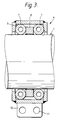
- the main clamp 4 is designed with sufficient width to encase the ring and to provide space for an impact absorbing member 7 on each side, as shown in Figure 3. In this manner, the clamp 4 will be accurately fixed in the correct localisation while very good transfer of forces is achieved from the outside of the gun, via both impact absorbing members 7, to the clamp proper, which is in turn secured to frame structure 2, 3.
- the clamp walls towards the internal clamp void may be inclined as indicated at 9 in Figure 3. Alternatively or additionally, the side walls of the ring may be inclined.
- a lug 10 with a securing hole 11 may be provided on the clamp, as indicated lowermost in Figure 3.
- airguns and other seismic equipment may be provided in a most shock-proof and protected manner, e.g. in frame structures as shown in Figure 1 and Figure 2, or be secured directly in the connection with a buoyancy means without too much wear occurring in the transfer elements, impact loads being absorbed by the shock absorbing members 7.
- Mounting of the fastening means is very simple, the fastening means is inexpensive in production, and is very reliable and efficient in use. Even though the embodiment has been described in connection with use for airguns, suspension of other impact sensitive equipment may be achieved with clamps of this or similar type.
- the void of the clamp need not necessarily be square, but may have other shapes.
- two "double" clamps 4 instead of one clamp 4 and one further clamp 5.
- the clamp may be mounted by welding or fastening with screws or bolts to the frame structures or other members, or lug structures as illustrated, may be used.
Landscapes
- Engineering & Computer Science (AREA)
- Physics & Mathematics (AREA)
- Life Sciences & Earth Sciences (AREA)
- Remote Sensing (AREA)
- Geology (AREA)
- Aviation & Aerospace Engineering (AREA)
- Acoustics & Sound (AREA)
- Environmental & Geological Engineering (AREA)
- Mechanical Engineering (AREA)
- General Life Sciences & Earth Sciences (AREA)
- General Physics & Mathematics (AREA)
- Geophysics (AREA)
- Vibration Prevention Devices (AREA)
- Road Signs Or Road Markings (AREA)
- Buildings Adapted To Withstand Abnormal External Influences (AREA)
- Cameras Adapted For Combination With Other Photographic Or Optical Apparatuses (AREA)
Description
- The invention relates to fastening members and arrangements for fixing seismic devices such as seismic energy sources of the airgun kind in a defined manner, for instance for fixing at least two devices firmly at a mutual distance in a frame structure.
- In seismic surveys at sea, an array of different seismic devices is towed in the water. In part, such devices are sensitive as regards impact or shock loads; in part, the towing system proper is sensitive to such loads. Special problems arise in connection with suspending such seismic acoustic sources, e.g. airguns, which are towed in arrays behind the seismic vessel, since they are suspended from below raft arrangements or the like. Due to the shock and impact loads triggered when the guns are fired, tugs and wear will result in the air conduits extending to the guns, in electric control lines, and in suspension members. Furthermore, wear and undesirable effects will also arise due to movement of the water, i.e. waves as well as general movement due to towing. Such problems will occur both with separately suspended guns and with guns suspended in framelike devices, in so called clusters.
- In an article in the magazine Geophysics, Vol.44, No. 5 (May 1979), pp 865-879 assembling of airguns in a group or a "cluster" is described, where the guns are attached to the frame at predetermined mutual distances, so that they may be fired while in a constant geometrical arrangement and without said geometrical arrangement being changed by or after firing. Such mounting of airguns in a frame structure results in a number of advantages in seismic surveys and this technique has been known for a long time.
- In US-PS No. 4 719 987 (corresponding to NO Patent Application 85 2459), another design is shown with seismic sources of energy suspended in groups, where the sources of energy are maintained at a predetermined mutual distance by means of a chain means which is attached to the sources by means of sleeves. Neither of the mentioned publications, however, discloses the mounting of the seismic energy sources in detail.
- The mounting proper of such sensitive seismic equipment, however, proved to be critical and decisive to the results achieved during survey, as shock and impact effects may cause distortion of signals and, in the case of a group arrangement of airguns in frame structures or chain constellations, mutual distances may be changed so that the desired results may not be achieved.
- According to a first aspect of the invention, there is provided a fastening member as defined in the appended
Claim 1. - According to a second aspect of the invention, there is provided a fastening arrangement as defined in the appended
Claim 8. - Preferred embodiments of the invention are defined in the other appended claims.
- It is thus possible to provide a fastening member and arrangement for use with circular seismic equipment, in which the problem caused by transfer of impact or shock loads is avoided while mechanical wear is reduced to a minimum on seismic equipment, on supply lines to seismic equipment, and on the suspension means proper. Furthermore, it is also possible to provide a fastening member and arrangement by means of which it is possible, in the case of localization in a frame of, e.g. seismic airguns, to maintain accurate positioning of the guns in relation to each other, to hydrophones, to the towing vessel, and to signal receiving cables (streamers).
- Such a fastening member and arrangement are useful both for single guns and for clustered guns.
- By using such fastening members and arrangements for seismic sources such as airguns, it is possible to provide a seismic system which is able to provide a stable output signature.
- The invention will be further described, by way of example, with reference to the accompanying drawings, in which:
- Figure 1 shows an arrangement of seismic airguns in a frame structure in a side elevation;
- Figure 2 shows the arrangement of Figure 1 in an end view; and
- Figure 3 shows a side elevation illustrating a main fastening member.
- The drawings show fastening members and arrangements for seismic airguns mounted in a cluster to be towed behind a seismic vessel in a manner corresponding to that disclosed in the two above mentioned publications.
-
Airguns 1 are provided in a frame comprising aninner portion 2 and anouter portion 3. Fastening members for theairguns 1 comprise amain member 4 and anadditional member 5. Both members are designed as hollow clamps with the void facing inwards, towards the airgun, and with a shape corresponding to that of the airgun to be able to envelope the latter tightly. Bothclamps clamps reference numeral 6. In the inner void of the clamps, impact and shock absorbing buffers are provided, preferably in the shape of circular, hose shaped members which are placed about the entire circumference of the airgun. These members are designated 7 in the drawings. A suitable material for these impact absorbing members is a polyurethane sold under the trade name "Adepren". - In the most strained area of the airgun, where the strongest impact absorption and, at the same time, the strongest hold is necessary, a
ring 8 is provided, preferably by welding, to be concentric with the airgun. Themain clamp 4 is designed with sufficient width to encase the ring and to provide space for animpact absorbing member 7 on each side, as shown in Figure 3. In this manner, theclamp 4 will be accurately fixed in the correct localisation while very good transfer of forces is achieved from the outside of the gun, via bothimpact absorbing members 7, to the clamp proper, which is in turn secured toframe structure - For further attachment of other seismic equipment, or to secure one single seismic gun, a
lug 10 with asecuring hole 11 may be provided on the clamp, as indicated lowermost in Figure 3. - By using two
clamps shock absorbing members 7. Mounting of the fastening means is very simple, the fastening means is inexpensive in production, and is very reliable and efficient in use. Even though the embodiment has been described in connection with use for airguns, suspension of other impact sensitive equipment may be achieved with clamps of this or similar type. Various modifications are possible. For instance, the void of the clamp need not necessarily be square, but may have other shapes. Also, it is possible to use two "double"clamps 4 instead of oneclamp 4 and onefurther clamp 5. The clamp may be mounted by welding or fastening with screws or bolts to the frame structures or other members, or lug structures as illustrated, may be used.
Claims (12)
- A fastening member for fixing in a defined manner a seismic device having a portion, which is subjected to greatest strain, of circular cross-section provided with a fastening ring, the fastening member being characterised by a rigid split substantially annular clamp (4, 5) with an inwardly facing void containing first and second shock absorbing members (7) for location on opposite sides of the ring (8) in contact with the ring (8) and the portion of circular cross-section.
- A fastening member as claimed in Claim 1, characterized in that the clamp is divided into sections fastened together by fastening means.
- A fastening member is claimed in Claim 2, characterized in that the clamp has two sections and the fastening means comprise a hinge and a bolt.
- A fastening member as claimed in Claim 2 or 3, characterized in that the clamp is asymmetrically divided.
- A fastening member as claimed in any one of the preceding claims, characterized in that the clamp has internal conical sides walls (9).
- A fastening member as claimed in any one of the preceding claims, characterized in that the clamp is provided with at least one lug (10) having a hole (11) for attachment of other equipment.
- A fastening member as claimed in any one of the preceding claims, characterized in that each shock absorbing member (7) is a circular hose-shaped member of a hard rubber material.
- A fastening arrangement for at least one seismic device, characterized by comprising a frame (2, 3) to which is fixed at least one fastening member as claimed in any one of the preceding claims.
- A fastening arrangement as claimed in Claim 8, characterized in that, for the or each seismic device (1), there is provided a fastening member as claimed in Claim 1 and a further fastening member comprising a rigid, split, substantially annular clamp (5) with an open inwardly facing void containing a single shock absorbing member (7) for another region of the seismic device (1).
- A fastening arrangement as claimed in Claim 8 or 9 for a plurality of seismic devices, characterized by at least one fastening device as claimed in any one of Claims 1 to 7 for each seismic device (1) arranged to fasten the seismic devices in the frame (2, 3) in fixed positions relative to each other.
- A fastening arrangement as claimed in any one of Claims 8 to 10, characterized in that the frame comprises an internal frame (2) to which the or each clamp is fixed and which is provided in an external frame (3).
- A fastening arrangement as claimed in Claim 11, characterized in that the or each clamp (4, 5) is welded to the internal frame (2).
Applications Claiming Priority (2)
| Application Number | Priority Date | Filing Date | Title |
|---|---|---|---|
| NO885044A NO165857C (en) | 1988-11-11 | 1988-11-11 | SEISMIC EQUIPMENT INSTALLATION BODY. |
| NO885044 | 1988-11-11 |
Publications (2)
| Publication Number | Publication Date |
|---|---|
| EP0368472A1 EP0368472A1 (en) | 1990-05-16 |
| EP0368472B1 true EP0368472B1 (en) | 1993-12-15 |
Family
ID=19891416
Family Applications (1)
| Application Number | Title | Priority Date | Filing Date |
|---|---|---|---|
| EP89310217A Expired - Lifetime EP0368472B1 (en) | 1988-11-11 | 1989-10-05 | A fastening member and fastening arrangement for seismic equipment |
Country Status (5)
| Country | Link |
|---|---|
| US (1) | US5051966A (en) |
| EP (1) | EP0368472B1 (en) |
| BR (1) | BR8905772A (en) |
| MY (1) | MY105139A (en) |
| NO (1) | NO165857C (en) |
Families Citing this family (9)
| Publication number | Priority date | Publication date | Assignee | Title |
|---|---|---|---|---|
| NO172872B (en) * | 1990-10-17 | 1993-06-07 | Geco As | DEVICE OF SEISMIC ENERGY SOURCES |
| NO173758C (en) * | 1991-09-04 | 1994-01-26 | Geco As | Apparatus for holding two or more seismic energy sources at a fixed distance from one another |
| US5463193A (en) * | 1992-05-08 | 1995-10-31 | Australia Sonar Systems Pty Ltd | Vibration isolation module |
| US5425003A (en) * | 1994-07-25 | 1995-06-13 | Grumman Aerospace Corporation | Acoustic transducer mounting clamp |
| US5980148A (en) * | 1997-11-18 | 1999-11-09 | Seismic Systems, Inc. | Dynamic system for maintaining spacing between two or more objects |
| US20040000446A1 (en) * | 2002-07-01 | 2004-01-01 | Barber Harold P. | Seismic signaling apparatus and method for enhancing signal repeatability |
| US7016261B2 (en) * | 2002-12-09 | 2006-03-21 | Baker Hughes, Incorporated | Deep penetrating focused array |
| EP2877395B1 (en) * | 2012-08-24 | 2016-01-20 | CGG Services SA | Autonomous underwater vehicle for marine seismic surveys |
| US11467297B1 (en) * | 2020-05-07 | 2022-10-11 | The United States Of America As Represented By The Secretary Of The Navy | Multimode hydrophone array |
Family Cites Families (7)
| Publication number | Priority date | Publication date | Assignee | Title |
|---|---|---|---|---|
| US3699507A (en) * | 1970-08-05 | 1972-10-17 | Dynamics Corp Massa Div | Baffle structure for underwater transducer array |
| US4038630A (en) * | 1975-10-28 | 1977-07-26 | Bolt Associates, Inc. | Airgun marine seismic survey streamer method and apparatus |
| US4719987A (en) * | 1984-06-19 | 1988-01-19 | Texas Instruments Incorporated | Bi-planar pontoon paravane seismic source system |
| US4658387A (en) * | 1984-11-23 | 1987-04-14 | Exxon Production Research Co. | Shallow water seismic energy source |
| JPS63502152A (en) * | 1985-12-05 | 1988-08-18 | フォーカス・リミテッド | Support member for pressure sensor |
| US4715023A (en) * | 1987-03-18 | 1987-12-22 | Mobil Oil Corporation | Coaxial, dual chamber seismic air gun |
| US4970046A (en) * | 1988-10-24 | 1990-11-13 | Exxon Production Research Company | Marine seismic source frame |
-
1988
- 1988-11-11 NO NO885044A patent/NO165857C/en unknown
-
1989
- 1989-10-05 EP EP89310217A patent/EP0368472B1/en not_active Expired - Lifetime
- 1989-10-25 MY MYPI89001480A patent/MY105139A/en unknown
- 1989-11-13 BR BR898905772A patent/BR8905772A/en unknown
- 1989-11-13 US US07/435,330 patent/US5051966A/en not_active Expired - Fee Related
Also Published As
| Publication number | Publication date |
|---|---|
| US5051966A (en) | 1991-09-24 |
| MY105139A (en) | 1994-08-30 |
| NO165857C (en) | 1991-04-17 |
| NO165857B (en) | 1991-01-07 |
| BR8905772A (en) | 1990-06-05 |
| NO885044L (en) | 1990-05-14 |
| EP0368472A1 (en) | 1990-05-16 |
| NO885044D0 (en) | 1988-11-11 |
Similar Documents
| Publication | Publication Date | Title |
|---|---|---|
| EP0497814B1 (en) | Seismic cable | |
| EP0733217B1 (en) | Hydrophone carrier | |
| AU2001278596B2 (en) | A housing for a seismic sensing element and a seismic sensor | |
| US8205711B2 (en) | Seismic source arrays | |
| US6839302B2 (en) | Acoustic emitters for use in marine seismic surveying | |
| EP0368472A1 (en) | A fastening member and fastening arrangement for seismic equipment | |
| US4970046A (en) | Marine seismic source frame | |
| WO1996033425A1 (en) | Uniform subsurface coverage at steep dips | |
| AU2001278596A1 (en) | A housing for a seismic sensing element and a seismic sensor | |
| AU2001250578A1 (en) | Acoustic emitters for use in marine seismic surveying | |
| US20030169045A1 (en) | Method and apparatus for a rigidly joined together and floating bucking and receiver coil assembly for use in airborne electromagnetic survey systems | |
| CN86102257A (en) | Distributed marine seismic source control system and method | |
| GB2186854A (en) | An angular member for a seismic cable | |
| US5412622A (en) | Apparatus for discriminating sound sources in a water environment | |
| NO348293B1 (en) | Triple-depth quad-source seismic acquisition | |
| US5164922A (en) | Device for firmly holding seismic means, especially sources of seismic energy | |
| EP1129369B1 (en) | Seismic cable with sensor elements being heavier than the cable | |
| EP0602152B1 (en) | A device for securing two or more seismic energy sources at fixed relative positions | |
| US3675193A (en) | Hoop stressed beam hydrophone | |
| US8542556B2 (en) | Directional seismic sensor array | |
| EA200000316A1 (en) | TOWED SEISMICRESENTABLE COSA USED IN MARINE SEISMIC DEVELOPMENT | |
| CN217560785U (en) | Self-contained hydrophone | |
| AU680489B2 (en) | Hydrophone carrier | |
| HK1013684B (en) | Hydrophone carrier |
Legal Events
| Date | Code | Title | Description |
|---|---|---|---|
| PUAI | Public reference made under article 153(3) epc to a published international application that has entered the european phase |
Free format text: ORIGINAL CODE: 0009012 |
|
| AK | Designated contracting states |
Kind code of ref document: A1 Designated state(s): GB IT NL |
|
| RIN1 | Information on inventor provided before grant (corrected) |
Inventor name: SKIFJELD, TORMOD Inventor name: KNUDSEN, LARS Inventor name: RUSSEL, MICHAEL, POLPERRO PARK FILLING STATION Inventor name: GJESTRUM, EINAR |
|
| 17P | Request for examination filed |
Effective date: 19900920 |
|
| 17Q | First examination report despatched |
Effective date: 19911004 |
|
| ITF | It: translation for a ep patent filed | ||
| GRAA | (expected) grant |
Free format text: ORIGINAL CODE: 0009210 |
|
| AK | Designated contracting states |
Kind code of ref document: B1 Designated state(s): GB IT NL |
|
| PLBE | No opposition filed within time limit |
Free format text: ORIGINAL CODE: 0009261 |
|
| STAA | Information on the status of an ep patent application or granted ep patent |
Free format text: STATUS: NO OPPOSITION FILED WITHIN TIME LIMIT |
|
| 26N | No opposition filed | ||
| REG | Reference to a national code |
Ref country code: GB Ref legal event code: IF02 |
|
| PGFP | Annual fee paid to national office [announced via postgrant information from national office to epo] |
Ref country code: NL Payment date: 20061003 Year of fee payment: 18 |
|
| PGFP | Annual fee paid to national office [announced via postgrant information from national office to epo] |
Ref country code: IT Payment date: 20061031 Year of fee payment: 18 |
|
| NLV4 | Nl: lapsed or anulled due to non-payment of the annual fee |
Effective date: 20080501 |
|
| PG25 | Lapsed in a contracting state [announced via postgrant information from national office to epo] |
Ref country code: NL Free format text: LAPSE BECAUSE OF NON-PAYMENT OF DUE FEES Effective date: 20080501 |
|
| PGFP | Annual fee paid to national office [announced via postgrant information from national office to epo] |
Ref country code: GB Payment date: 20081001 Year of fee payment: 20 |
|
| PG25 | Lapsed in a contracting state [announced via postgrant information from national office to epo] |
Ref country code: IT Free format text: LAPSE BECAUSE OF NON-PAYMENT OF DUE FEES Effective date: 20071005 |
|
| REG | Reference to a national code |
Ref country code: GB Ref legal event code: PE20 Expiry date: 20091004 |
|
| PG25 | Lapsed in a contracting state [announced via postgrant information from national office to epo] |
Ref country code: GB Free format text: LAPSE BECAUSE OF EXPIRATION OF PROTECTION Effective date: 20091004 |