EP0367604B1 - Dispositif de distribution pour récipients distributeurs pressurisés - Google Patents
Dispositif de distribution pour récipients distributeurs pressurisés Download PDFInfo
- Publication number
- EP0367604B1 EP0367604B1 EP89311356A EP89311356A EP0367604B1 EP 0367604 B1 EP0367604 B1 EP 0367604B1 EP 89311356 A EP89311356 A EP 89311356A EP 89311356 A EP89311356 A EP 89311356A EP 0367604 B1 EP0367604 B1 EP 0367604B1
- Authority
- EP
- European Patent Office
- Prior art keywords
- valve
- container
- cup
- dispensing
- chamber
- Prior art date
- Legal status (The legal status is an assumption and is not a legal conclusion. Google has not performed a legal analysis and makes no representation as to the accuracy of the status listed.)
- Expired - Lifetime
Links
- 239000007788 liquid Substances 0.000 claims abstract description 34
- 239000012263 liquid product Substances 0.000 claims abstract description 14
- IJGRMHOSHXDMSA-UHFFFAOYSA-N Atomic nitrogen Chemical compound N#N IJGRMHOSHXDMSA-UHFFFAOYSA-N 0.000 claims abstract description 12
- 239000003380 propellant Substances 0.000 claims abstract description 12
- 229910052757 nitrogen Inorganic materials 0.000 claims abstract description 6
- 239000000463 material Substances 0.000 claims description 4
- 230000015572 biosynthetic process Effects 0.000 claims description 3
- 238000002788 crimping Methods 0.000 claims description 3
- QJGQUHMNIGDVPM-UHFFFAOYSA-N nitrogen group Chemical group [N] QJGQUHMNIGDVPM-UHFFFAOYSA-N 0.000 claims 1
- 239000007789 gas Substances 0.000 abstract description 9
- 230000008901 benefit Effects 0.000 description 8
- 238000007789 sealing Methods 0.000 description 5
- CURLTUGMZLYLDI-UHFFFAOYSA-N Carbon dioxide Chemical compound O=C=O CURLTUGMZLYLDI-UHFFFAOYSA-N 0.000 description 4
- 239000006196 drop Substances 0.000 description 3
- 239000000047 product Substances 0.000 description 3
- 230000009471 action Effects 0.000 description 2
- 229910002092 carbon dioxide Inorganic materials 0.000 description 2
- 239000001569 carbon dioxide Substances 0.000 description 2
- 230000007423 decrease Effects 0.000 description 2
- 239000003814 drug Substances 0.000 description 2
- 229930195733 hydrocarbon Natural products 0.000 description 2
- 150000002430 hydrocarbons Chemical class 0.000 description 2
- 230000037452 priming Effects 0.000 description 2
- 125000006850 spacer group Chemical group 0.000 description 2
- 239000004215 Carbon black (E152) Substances 0.000 description 1
- 230000006835 compression Effects 0.000 description 1
- 238000007906 compression Methods 0.000 description 1
- 238000010276 construction Methods 0.000 description 1
- 239000002537 cosmetic Substances 0.000 description 1
- 230000000881 depressing effect Effects 0.000 description 1
- 230000000994 depressogenic effect Effects 0.000 description 1
- 230000006866 deterioration Effects 0.000 description 1
- 229910001873 dinitrogen Inorganic materials 0.000 description 1
- 239000013536 elastomeric material Substances 0.000 description 1
- 230000007613 environmental effect Effects 0.000 description 1
- 239000003889 eye drop Substances 0.000 description 1
- 229940012356 eye drops Drugs 0.000 description 1
- 239000012530 fluid Substances 0.000 description 1
- NBVXSUQYWXRMNV-UHFFFAOYSA-N fluoromethane Chemical compound FC NBVXSUQYWXRMNV-UHFFFAOYSA-N 0.000 description 1
- 231100001261 hazardous Toxicity 0.000 description 1
- 230000004941 influx Effects 0.000 description 1
- 230000003993 interaction Effects 0.000 description 1
- 238000002955 isolation Methods 0.000 description 1
- 238000004519 manufacturing process Methods 0.000 description 1
- 238000000465 moulding Methods 0.000 description 1
- 229920003052 natural elastomer Polymers 0.000 description 1
- 229920001194 natural rubber Polymers 0.000 description 1
- 230000035515 penetration Effects 0.000 description 1
- 239000004033 plastic Substances 0.000 description 1
- 229920003023 plastic Polymers 0.000 description 1
- 230000009467 reduction Effects 0.000 description 1
- 230000000717 retained effect Effects 0.000 description 1
- 239000007921 spray Substances 0.000 description 1
- 230000003068 static effect Effects 0.000 description 1
- 229920003051 synthetic elastomer Polymers 0.000 description 1
- 239000005061 synthetic rubber Substances 0.000 description 1
- 229920002725 thermoplastic elastomer Polymers 0.000 description 1
- 230000008719 thickening Effects 0.000 description 1
Images

Classifications
-
- B—PERFORMING OPERATIONS; TRANSPORTING
- B65—CONVEYING; PACKING; STORING; HANDLING THIN OR FILAMENTARY MATERIAL
- B65D—CONTAINERS FOR STORAGE OR TRANSPORT OF ARTICLES OR MATERIALS, e.g. BAGS, BARRELS, BOTTLES, BOXES, CANS, CARTONS, CRATES, DRUMS, JARS, TANKS, HOPPERS, FORWARDING CONTAINERS; ACCESSORIES, CLOSURES, OR FITTINGS THEREFOR; PACKAGING ELEMENTS; PACKAGES
- B65D83/00—Containers or packages with special means for dispensing contents
- B65D83/14—Containers or packages with special means for dispensing contents for delivery of liquid or semi-liquid contents by internal gaseous pressure, i.e. aerosol containers comprising propellant for a product delivered by a propellant
- B65D83/44—Valves specially adapted therefor; Regulating devices
- B65D83/52—Valves specially adapted therefor; Regulating devices for metering
- B65D83/54—Metering valves ; Metering valve assemblies
Definitions
- This invention relates to dispensing apparatus for dispensing a liquid product from a pressurised dispensing container where it is required to dispense an accurately metered quantity of liquid product.
- Pressurised dispensing containers have been used for dispensing a wide variety of liquid products and in the past have typically employed a liquid propellant mixed with the liquid product such as a hydrocarbon or fluorocarbon having a sufficiently high vapour pressure at normal working temperatures to propel the liquid product through the dispensing apparatus.
- a liquid propellant mixed with the liquid product such as a hydrocarbon or fluorocarbon having a sufficiently high vapour pressure at normal working temperatures to propel the liquid product through the dispensing apparatus.
- Alternative dispensing apparatus such as metering pumps have been adopted to avoid the use of propellants altogether but there are a number of inherent disadvantages with such pumps since they generally require the user to depress an actuator having a long dispensing stroke and relatively high actuation force.
- the accuracy of the metered dose in a metering pump is generally found to be less than in the case of a metering valve used with a pressurised dispensing container for which the valve actuator generally has a short stroke with low actuating force.
- the accuracy of the metered dose is very important.
- the inlet valve means comprises an annular seal portion of the sleeve co-operating with an inner end portion of the stem extending through the seal portion, the communicating means comprising a cup within which the valve body is nestably received and seal means operable between the mouth of the cup and an outer end of the valve such that a closed collecting chamber communicating with the inlet valve means is defined between the valve and the cup.
- valve end In referring to the "outer end" of the valve the intended meaning is that the valve end which is outermost with respect to the container in use.
- the apparatus is adapted for dispensing from a container in an upright orientation in which the valve is uppermost and the communicating means comprises a dip tube extending from the cup to the lowermost part of the container.
- the apparatus may be adapted for dispensing from a container in an inverted orientation in which the valve is lowermost and wherein the communicating means comprises one or more apertures in the cup wall adjacent the cup mouth.
- the valve includes a radially outwardly projecting annular flange at its outer end
- the cup includes a radially outwardly projecting annular flange adjacent its mouth
- a sleeve includes a radially outwardly projecting flange which is compressed between the valve flange and the cup flange to thereby constitute the seal means.
- valve and cup are received within a ferrule through which an actuator stem of the valve extends and the cup is maintained in sealing relationship with the valve by a crimped formation of the ferrule.
- the apparatus is assemblable with the container by crimping the ferrule into engagement with a lip of the container and includes further seal means operable between the cup flange and container lip.
- the sleeve further comprises an annular shoulder portion nestably receiving the inner end of the body, the shoulder portion and the seal portion being integrally formed of relatively thick and thin material respectively whereby the shoulder portion and seal portion are relatively rigid and flexible respectively so as to positively locate the sleeve upon the valve body whilst permitting deformation of the seal portion.
- seal portion can be made sufficiently flexible to allow manufacturing tolerances to be relaxed with respect to the relative positions of the stem and the seal portion.
- the shoulder portion can also be made sufficiently rigid that the sleeve is positively held in a static position on the valve body so that there is a higher degree of isolation between the flexure of the seal portion and flexure of the collapsible side walls of the sleeve which define the metering chamber.
- the side walls, the shoulder portion and the seal portion may therefore be integrally formed without the disadvantage of interaction in the operation of the inlet valve means and the collapsible chamber.
- a further advantage is that the sleeve is readily mouldable in a single simple operation.
- the channel means comprises a slot in the body extending axially from the inner end of the body into communication with the collapsible chamber, at least the inner end portion of the slot extending radially into the internal chamber to provide a flowpath between the collapsible chamber and a location in the internal chamber adjacent to the inlet valve means.
- An advantage of such a slot is that the flow path it provides enables the collapsible chamber to be refilled with fluid passing through the inlet valve means directly into the collapsible chamber via the slot when the valve is in the closed condition.
- This arrangement is distinguished from prior art arrangements in which the refill flow path takes an indirect path from the inlet valve means, along the length of an internal chamber and then through an access port into the collapsible chamber. The present arrangement thereby provides faster refilling of the metering chamber.
- a further advantage is that the slot is easily mouldable as a feature of the body since it does not require the use of radially moving moulding tools.
- the seal portion of the sleeve comprises a tubular projection having a radially inwardly directed annular rib of part circular cross-section.
- An advantage of such a rib is that friction between the seal portion and the stem is reduced to thereby provide smoothness of operation.
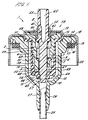
- a dispensing apparatus 1 comprises a valve 2 which is nestably received within a cup 3 formed of a rigid plastics material.
- the valve 2 is of the metering type in which an elastomeric sleeve 4 overlays an external surface 5 of a body 6 of the valve such that an annular metering chamber 7 is defined therebetween.
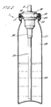
- the valve 2 is fitted in use to a pressurised dispensing container 21 as shown in Figure 2 for dispensing liquid 24.
- the valve 2 is actuated by manual depression of a valve stem 8 which is reciprocatable axially within the body 6 and the operation of the valve is such that at each depression of the stem a volume of liquid equal to the contents of the metering chamber 7 is discharged through the stem.
- the stem is returned to its rest position by pressure of a return spring 9 at which time the metering chamber 7 is replenished by an influx of liquid which enters the valve 2 through an inlet opening 10 at the innermost end 12 of the valve with respect to the container 21.
- the external surface 5 is stepped in diameter so as to progressively decrease in size in the inward axial direction with respect to the container 21.
- the elastomeric sleeve 4 has a tubular side wall 50 which coaxially overlays the body 6. The sleeve 4 fits sealingly around an outer end 51 of the valve body 6.
- An annular shoulder portion 52 is formed by a thickening of the sleeve material such that the shoulder portion extends radially inwardly of the side wall 50 into contact with an inner end 68 of the valve body 6. Because of the stepped taper of the external surface 5 the annular metering chamber 7 is defined between the sleeve 4 and a portion 53 of the external surface located intermediate the outer end 51 and the inner end 68 of the valve body 6. The shoulder portion 52 is contoured to nestably receive the inner end 68 of the valve body 6 and in this way the sleeve 4 is positively located in coaxial alignment with the body.
- the annular metering chamber 7 is thereby closed at its innermost end with respect to the container 21 by the annular shoulder 52.
- the body 6 defines an internal chamber 54 which extends axially from an opening 20 through which an outer end 55 of the stem 8 extends and an inlet aperture 56 through which an inner end portion 57 of the stem extends.
- An outlet valve means 58 is formed in the opening 20 by a radially outwardly projecting annular flange 59 of the stem 8 cooperating with an annular elastomeric seal 60 which is held in sealing contact with the body 6 by a ferrule 18.
- the seal 60 includes an annular recess 40 halfway along its axial extent. The purpose of the recess 40 is to reduce the contact area between the stem 8 and the seal 60 in order to minimise friction of forces which would otherwise impede the smooth operation of the valve 2.
- a radially extending bore 61 of the stem 8 communicates with an axially extending outlet channel 62 within the stem, the bore being disposed outside of the internal chamber 54 in the closed condition of the valve 2 as shown in Figure 1 in which the position of the stem is such that the bore is overlaid by the seal 60.
- the seal 60 not only prevents leakage of liquid from the internal chamber 54 around the stem 8 when the valve 2 is closed but also prevents the bore 61 from communicating directly with the atmosphere. This prevents any deterioration of the liquid trapped in the stem 8 when the apparatus is not in use and also prevents leakage for drain back from the stem onto the exterior of the ferrule 18.
- the stem 8 is biassed outwardly by a helical spring 9 held in compression between the flange 59 of the stem and a shoulder 63 formed in the internal chamber 54.
- An inlet valve means 64 comprises a tubular extension 66 of the sleeve 4 having a radially inwardly projecting rib 65 which is dimensioned to provide a sealing fit around the stem 8 when the valve 2 is open (and the inlet valve means 64 is closed).
- the inner end portion 57 of the stem 8 is reduced in diameter such that an annular opening 10 is formed between the stem and the rib 65 when the valve 2 is in a closed condition as shown in Figure 1 (and therefore the inlet valve means 64 is in an open condition).
- An axially extending slot 67 is formed in the inner end 68 of the body 6 and the slot extends axially to a greater extent than the annular shoulder portion 52 of the sleeve so as to communicate with the annular metering chamber 7.
- the slot 67 has an inner end portion 69 which extends radially into communication with the internal chamber 54 at a location which is adjacent to the inlet valve means 64.
- the internal chamber 54 is of reduced diameter at this location but axially extending spacer ribs 70 are provided within the internal chamber 54 and project radially inwardly to maintain clearance between the stem 8 and the internal chamber walls.
- the spacer ribs 65 also serve to maintain the stem 8 in axial alignment with the valve body 6.
- the sleeve flange 15, the side wall 50, the shoulder portion 52 and the extension 66 on the sleeve including the rib 65 are all integrally formed of an elastomeric material which may be a natural or synthetic rubber or may be a thermoplastic elastomer.
- the radial thickness of the shoulder 52 is 1.4 mm compared with the much thinner thickness on the extension 66 which is 0.5 mm. Consequently the shoulder 52 is relatively rigid whereas the extension 66 is relatively flexible.
- the rib 65 projects radially inwardly by 0.54 mm from the extension 66.
- the radial thickness of the side wall 50 is 0.55 mm so that the side wall is relatively flexible.
- the rib 65 is of semi-circular cross-section and in its relaxed state has an internal diameter which is slightly less than the diameter of the stem 8 but greater than the diameter of the inner end portion 57 of the stem.
- the valve 2 is actuated by depressing the stem 8 so as to move inwardly with respect to the container 21 such that the bore 61 communicates with the internal chamber 54 to thereby open the outlet valve means 58.
- the depressed stem 8 makes sealing contact with the rib 65 of the extension 66 such that the inlet valve means 64 is closed. Penetration of the stem 8 through the rib 65 is accomodated by resilient deformation of the extension 66.
- the cup 3 is generally cylindrical in shape and of larger internal diameter than the external diameter of the sleeve 4 such that an annular collecting chamber 11 is defined between the cup and the valve 2.
- the collecting chamber 11 extends around the inner end 12 of the valve 2 such that the metering chamber 7 is replenished from liquid drawn from the collecting chamber 11.
- the valve body 6 has a radially projecting valve flange 13 at its upper end which extends above a radially extending annular cup flange 14 of the cup 3.
- a radially projecting annular sleeve flange 15 formed integrally with the elastomeric sleeve 4 is sandwiched between the cup flange 14 and the valve flange 13 so as to provide sealing action between the valve body 6 and the cup 3.
- the upper end of the collecting chamber 11 is thereby closed.
- the cup flange 14 has an under surface 16 against which a gasket 17 is held in place by a ferrule 18 within which the valve 2 and cup 3 are located, the ferrule including an annular crimped formation 19 which retains the gasket, the cup, the sleeve and the valve in their respective assembled positions.
- the stem 8 projects through an opening 20 in the ferrule 18.
- the apparatus 1 is fitted on to a container 21 in the form of a roll topped can by crimping a lower portion 22 of the ferrule 18 around a lip 23 of the container such that the lip is sealed to the cup flange 14 by action of the gasket 17.
- the cup 3 communicates with liquid 24 contained in the lower part of the container 21 by means of a dip tube 25 which is received within an axially depending tubular extension 26 of the cup.
- the dip tube 25 is retained within the extension 26 by means of a ramped internal rib 27 which is arranged to indent and grip the dip tube as shown in Figure 1.
- the dispensing apparatus 1 is assembled with the container 21 as shown in Figure 2 and the container partially filled with liquid 24.
- the head space 28 above the liquid 24 is pressurised with nitrogen gas.
- Operation of the valve 2 is by depression of the stem 8 which will generally receive an actuator (not shown) having a nozzle providing the desired spray characteristics.
- the valve requires a number of initial priming strokes to fill the dip tube, the collecting chamber 11 defined by the cup 3 and the internal cavities of the valve 2 including the metering chamber 7.
- depression of the stem 8 actuates the valve 2 into its open condition in which the internal chamber 54 is vented to atmospheric pressure and the flow of liquid commences from the internal chamber through the bore 61 to be dispensed through the outlet channel 62.
- This reduction of pressure within the internal chamber 54 is communicated through the slot 67 to the annular metering chamber 7 so that a pressure differential is established across the side wall 50 which collapses radially inwardly towards the body 6 thereby displacing liquid from the metering chamber through the slot and into the internal chamber.
- An equilibrium condition will then be reached in which further deformation of the side wall 50 is prevented by contact with the body 6 and the flow of liquid is then stopped.
- valve stem 8 is then released and returned under spring pressure to its normal position as shown in Figure 1 and in doing so closes the outlet valve means 58 and opens the inlet valve means 64.
- the side wall 50 then relaxes to its cylindrical undeformed shape and in doing so creates suction within the metering chamber 7.
- a refill flow path is at the same time established from within the container 21, through the opening 10 around the inner end portion 57 of the stem, into the internal chamber 54 at a location adjacent to the inlet valve means 64 and through the slot 67 to recharge the metering chamber with liquid.
- An equlibrium condition will then be reached in which pressure is equalised on either side of the side wall 50 and the refill flow is then stopped.
- the valve is then ready for further actuation.
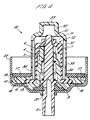
- the apparatus 30 is adapted for dispensing liquid from a container 21 which is inverted in use such that the valve 2 is lowermost.
- the apparatus 30 has a modified cup 31 in which a tubular extension 32 has a closed end 33.
- Apertures 34 are provided in the side wall 35 of the cup closely adjacent to the gasket 17 so that in the inverted position as shown in Figure 4 any residual product liquid within the container is accessible to the apertures thereby ensuring that as much of the liquid as possible is dispensed from the container.
- FIG. 5 An alternative apparatus 41 is shown in Figure 5 where corresponding references to those used in Figures 1 and 2 are used where appropriate.
- the apparatus 41 is adapted for dispensing liquid from a container which is upright in use such that the valve 2 is uppermost.
- the components of the apparatus 41 correspond generally to those of the apparatus 1 of Figure 1 but the apparatus is dimensioned to engage a broad rimmed container such as a bottle (not shown).
- Alternative embodiments of the present invention are envisaged in which alternative collapsible chamber metering valves are contained within a cup as hereinbefore disclosed.
- the apparatus may be used with relatively insoluble gas propellants such as nitrogen or alternatively with relatively soluble gases such as carbon dioxide.
- the apparatus may be used with conventional aerosol propellants such as hydrocarbons or chlorofluorocarbons (CFC). It is however a particular advantage of this invention that non-hazardous and inexpensive gaseous propellant such as nitrogen can be used without prejudice to the consistency of the metered quantity dispensed.
- the invention has application to pharmaceutical and cosmetic products in particular where accurate metered dosages are required.
- the apparatus of the present invention may be used with compressed gas propellants other than nitrogen such as carbon dioxide for example.
- the apparatus may also be used at relatively low pressures to dispense individual drops of product liquid. If for example eye drops are to be dispensed then an initial fill pressure of 310 kPa (45 psi) would typically be used to ensure that only a very low flow rate was dispensed at each actuation of the valve. Other applications where individual drops are to be dispensed would include veterinary use.
- the apparatus may be adapted to dispense a dose of medicament in the form of a gel.
Claims (11)
- Dispositif de distribution (1) pour distribuer un produit liquide (24) depuis un récipient distributeur pressurisé (21) comprenant une vanne de dosage (2) à chambre déformable dans laquelle un manchon élastomère (4) recouvre une surface externe (53) du corps de vanne (6) pour définir une chambre de dosage (7) entre eux et est déformable lors de l'actionnement de la vanne en contact coïncidant sensiblement avec la surface externe de manière qu'un volume de produit liquide soit distribué, étant égal au volume du produit liquide déplacé depuis la chambre de dosage, dans lequel le corps de vanne définit une chambre interne (54) et un conduit (67) communiquant entre la chambre interne et la chambre déformable, une tige d'actionnement de vanne coulissant axialement (8) s'étendant coaxialement dans la chambre interne, un moyen de décharge (58) opérant entre la tige et le corps à l'extrémité externe de la chambre interne pour distribuer le liquide depuis celle-ci dans une condition ouverte de la vanne, un moyen d'admission (64) opérant entre la tige et le corps à l'extrémité interne de la chambre interne pour admettre le liquide dans celle-ci dans une condition fermée de la vanne et un moyen de communication (25) communiquant à l'utilisation entre le moyen d'admission et la partie du récipient dans laquelle un produit liquide est contenu lorsque le récipient est tenu dans une orientation prédéterminée pour l'actionnement de la vanne, caractérisé en ce que le moyen d'admission comprend une portion d'étanchéité annulaire (65,66) du manchon coopérant avec une portion d'extrémité interne (57) de la tige s'étendant à travers la portion d'étanchéité, le moyen de communication comprenant une coupelle (3) dans laquelle le corps de vanne est reçu par emboîtement et un moyen d'étanchéité (15) opérant entre l'ouverture de la coupelle et une extrémité externe de la vanne de manière qu'une chambre collectrice fermée (11) communiquant avec le moyen d'admission soit définie entre la vanne et la coupelle.
- Dispositif de distribution selon la revendication 1, adapté à la distribution depuis un récipient tenu droit dans lequel la vanne se trouve en haut et dans lequel le moyen de communication comprend un tube à immersion (25) s'étendant de la coupelle à la partie la plus basse du récipient.
- Dispositif de distribution selon la revendication 1, adapté à la distribution depuis un récipient tenu renversé dans lequel la vanne se trouve en bas et dans lequel le moyen de communication comprend une ou plusieurs ouvertures (34) dans la paroi (35) de la coupelle adjacente à l'ouverture de la coupelle.
- Dispositif de distribution selon l'une quelconque des revendications précédentes, dans lequel le corps de vanne comprend un rebord annulaire (13) se projetant radialement vers l'extérieur à son extrémité externe (51), la coupelle comprend un rebord annulaire (14) se projetant radialement vers l'extérieur, adjacent à l'ouverture de la coupelle et dans lequel le manchon comprend un rebord (13) se projetant radialement vers l'extérieur qui est comprimé entre le rebord de la vanne et le rebord de la coupelle de manière à constituer le moyen d'étanchéité.
- Dispositif de distribution selon la revendication 4, dans lequel la vanne et la coupelle sont reçues au sein d'une ferrure (18) et dans lequel la coupelle est maintenue en relation d'étanchéité avec la vanne par une formation sertie (19) de la ferrure.
- Dispositif de distribution selon la revendication 5, dans lequel le dispositif peut être assemblé au récipient en sertissant la ferrure en engagement avec un rebord (23) du récipient et comprenant un autre moyen d'étanchéité (17) agissant entre le rebord de la coupelle et le rebord du récipient.
- Dispositif de distribution selon l'une quelconque des revendications précédentes, dans lequel le manchon comprend en outre un épaulement annulaire (52) recevant par emboîtement l'extrémité interne du corps, l'épaulement et la portion d'étanchéité étant formés d'un seul tenant en un matériau relativement épais et mince respectivement de manière que l'épaulement et la portion d'étanchéité soient relativement rigide et flexible respectivement afin de positionner de manière sûre le manchon sur le corps de vanne tout en permettant à la portion d'étanchéité de se déformer.
- Dispositif de distribution selon l'une quelconque des revendications précédentes, dans lequel le conduit comprend une fente (67) dans le corps s'étendant axialement depuis l'extrémité interne du corps en communication avec la chambre déformable, au moins la portion d'extrémité interne (69) de la fente s'étendant radialement dans la chambre interne pour former un passage d'écoulement entre la chambre déformable et un emplacement dans la chambre interne adjacent au moyen d'admission.
- Dispositif de distribution selon l'une quelconque des revendications précédentes, dans lequel la portion d'étanchéité du manchon comprend une projection tubulaire (66) comportant une nervure annulaire (65) dirigée radialement vers l'intérieur de section transversale partiellement circulaire.
- Dispositif de distribution selon l'une quelconque des revendications précédentes combiné avec un récipient distributeur, dans lequel le récipient renferme une quantité de produit liquide et une quantité de gaz propulseur qui est pratiquement insoluble dans le liquide.
- Dispositif de distribution selon la revendication 10, dans lequel le gaz propulseur est de l'azote.
Priority Applications (1)
| Application Number | Priority Date | Filing Date | Title |
|---|---|---|---|
| AT89311356T ATE87877T1 (de) | 1988-11-02 | 1989-11-02 | Vorrichtung zum ausgeben des inhalts von unter druck stehenden behaeltern. |
Applications Claiming Priority (2)
| Application Number | Priority Date | Filing Date | Title |
|---|---|---|---|
| GB888825632A GB8825632D0 (en) | 1988-11-02 | 1988-11-02 | Dispensing apparatus for pressurised dispensing containers |
| GB8825632 | 1988-11-02 |
Publications (2)
| Publication Number | Publication Date |
|---|---|
| EP0367604A1 EP0367604A1 (fr) | 1990-05-09 |
| EP0367604B1 true EP0367604B1 (fr) | 1993-04-07 |
Family
ID=10646180
Family Applications (1)
| Application Number | Title | Priority Date | Filing Date |
|---|---|---|---|
| EP89311356A Expired - Lifetime EP0367604B1 (fr) | 1988-11-02 | 1989-11-02 | Dispositif de distribution pour récipients distributeurs pressurisés |
Country Status (21)
| Country | Link |
|---|---|
| US (1) | US5037013A (fr) |
| EP (1) | EP0367604B1 (fr) |
| JP (1) | JP2634258B2 (fr) |
| KR (1) | KR960007219B1 (fr) |
| CN (1) | CN1021317C (fr) |
| AT (1) | ATE87877T1 (fr) |
| AU (1) | AU624648B2 (fr) |
| CA (1) | CA2001431A1 (fr) |
| DE (1) | DE68905901T2 (fr) |
| DK (1) | DK547389A (fr) |
| ES (1) | ES2039875T3 (fr) |
| FI (1) | FI89698C (fr) |
| GB (2) | GB8825632D0 (fr) |
| HK (1) | HK29095A (fr) |
| IE (1) | IE62435B1 (fr) |
| MY (1) | MY104457A (fr) |
| NO (1) | NO894351L (fr) |
| NZ (1) | NZ231208A (fr) |
| PT (1) | PT92172B (fr) |
| RU (1) | RU2005682C1 (fr) |
| ZA (1) | ZA898098B (fr) |
Families Citing this family (39)
| Publication number | Priority date | Publication date | Assignee | Title |
|---|---|---|---|---|
| US5340570A (en) * | 1991-11-18 | 1994-08-23 | Shiseido Co., Ltd. | Dispensing system for sprayable gel-type hair conditioner |
| JP2578728Y2 (ja) * | 1992-01-27 | 1998-08-13 | 株式会社三谷バルブ | エアゾール容器 |
| JP2606516Y2 (ja) * | 1992-07-24 | 2000-11-27 | 株式会社三谷バルブ | エアゾール容器用定量バルブ |
| JP3339900B2 (ja) * | 1993-03-01 | 2002-10-28 | 株式会社ダイゾー | 定量噴射型エアゾール容器 |
| US5484088A (en) * | 1994-04-29 | 1996-01-16 | Martin; James H. | Presettable indexed adjustable dose dispenser |
| DE4426821A1 (de) * | 1994-07-28 | 1996-02-01 | Coster Tecnologie Speciali Spa | Dosierventil für die Abgabe von unter Druck stehenden Fluiden |
| EP0726081B1 (fr) * | 1994-08-29 | 2000-06-28 | Osaka Shipbuilding Co., Ltd. | Recipient d'aerosol a debit constant |
| FR2740527B1 (fr) * | 1995-10-31 | 1998-01-02 | Valois | Tige de soupape a faibles frottements |
| GB2316673B (en) * | 1996-09-03 | 1999-12-29 | Bespak Plc | Metering valve |
| GB9805938D0 (en) * | 1998-03-19 | 1998-05-13 | Glaxo Group Ltd | Valve for aerosol container |
| GB9918627D0 (en) | 1999-08-07 | 1999-10-13 | Glaxo Group Ltd | Valve |
| GB9918626D0 (en) * | 1999-08-07 | 1999-10-13 | Glaxo Group Ltd | Valve |
| GB2361228A (en) * | 2000-04-14 | 2001-10-17 | Presspart Mfg Ltd | Metering valve |
| US6446880B1 (en) | 2000-08-02 | 2002-09-10 | S.C. Johnson & Son, Inc. | Replaceable reservoir for an atomizing apparatus |
| GB2367809A (en) * | 2000-10-12 | 2002-04-17 | Bespak Plc | Metering valve with collapsible chamber |
| EP1414716A1 (fr) * | 2001-08-11 | 2004-05-06 | Aventis Pharma Limited | Distributeur a aerosol pressurise |
| JP2005515132A (ja) | 2001-12-31 | 2005-05-26 | スリーエム イノベイティブ プロパティズ カンパニー | 計量弁に用いる弁ステム |
| GB2385315B (en) * | 2002-01-15 | 2004-06-30 | Bespak Plc | Improvements in or relating to valves for dispensers |
| US6832704B2 (en) | 2002-06-17 | 2004-12-21 | Summit Packaging Systems, Inc. | Metering valve for aerosol container |
| DE102004034626A1 (de) * | 2004-06-17 | 2006-01-12 | Seaquist Perfect Dispensing Gmbh | Dosierventil und Vorrichtung zur Abgabe einer vorzugsweise kosmetischen Flüssigkeit |
| US8678248B2 (en) | 2007-12-11 | 2014-03-25 | Summit Packaging Systems Inc | Metering valve |
| KR101040968B1 (ko) * | 2008-08-27 | 2011-06-16 | 주식회사 승일 | 파우치를 구비하는 정량 분사 용기 및 그의 밸브 조립체 |
| JP5647767B2 (ja) * | 2009-03-11 | 2015-01-07 | 株式会社丸一 | エアゾール定量バルブ |
| GB2470403A (en) * | 2009-05-21 | 2010-11-24 | Consort Medical Plc | Valve assembly with valve stem for use with an aerosol canister |
| FR2950037B1 (fr) * | 2009-09-11 | 2011-12-16 | Rexam Pharma La Verpilliere | Dispositif de distribution de liquide |
| GB0917731D0 (en) * | 2009-10-09 | 2009-11-25 | Univ Salford | Liquid dispensing apparatus |
| CN102725209A (zh) | 2009-10-09 | 2012-10-10 | 索尔福德大学 | 液体分配仪器 |
| WO2011045630A1 (fr) * | 2009-10-16 | 2011-04-21 | Sixtem Life Srl | Dispositif pour distribuer une ou plusieurs substances de traitement de la peau et procédé d'utilisation dudit dispositif |
| PT2597055E (pt) * | 2010-07-20 | 2016-01-14 | Toyo Aerosol Ind Co | Dispositivo de aerossol para distribuição de múltiplos fluidos |
| FR2968283B1 (fr) * | 2010-12-03 | 2013-01-04 | Valois Sas | Valve de distribution de produit fluide. |
| FR3000945B1 (fr) * | 2013-01-15 | 2016-02-05 | Lindal France | Valve doseuse |
| FR3019535B1 (fr) * | 2014-04-02 | 2016-03-25 | Rexam Healthcare La Verpillier | Ensemble de distribution d'un aerosol comportant une zone de contact perfectionnee avec un col de reservoir |
| CN104595541A (zh) * | 2015-01-26 | 2015-05-06 | 中山市美捷时包装制品有限公司 | 一种倒置定量阀 |
| US10179690B2 (en) | 2016-05-26 | 2019-01-15 | Rai Strategic Holdings, Inc. | Aerosol precursor composition mixing system for an aerosol delivery device |
| DE102016212892C5 (de) * | 2016-07-14 | 2020-01-30 | F. Holzer Gmbh | Pumpkopf sowie Dosiervorrichtung |
| BE1025177B1 (nl) * | 2017-09-21 | 2018-11-29 | Altachem Nv | Klep voor een houder |
| CN111526767B (zh) * | 2017-12-29 | 2022-12-09 | 高露洁-棕榄公司 | 分配器系统 |
| IT201900015830A1 (it) * | 2019-09-06 | 2021-03-06 | Coster Tecnologie Speciali Spa | Dispositivo di erogazione di una sostanza fluida |
| GB2621351A (en) | 2022-08-09 | 2024-02-14 | The Salford Valve Company Ltd | Metered dosage apparatus |
Citations (1)
| Publication number | Priority date | Publication date | Assignee | Title |
|---|---|---|---|---|
| US3092107A (en) * | 1960-02-23 | 1963-06-04 | Nathan D Froot | Hypodermic injection device |
Family Cites Families (12)
| Publication number | Priority date | Publication date | Assignee | Title |
|---|---|---|---|---|
| US2886217A (en) * | 1957-05-20 | 1959-05-12 | Riker Laboratories Inc | Dispensing device |
| GB872187A (en) * | 1958-11-10 | 1961-07-05 | Risdon Mfg Co | Metering valves for pressurised containers |
| FR1298425A (fr) * | 1961-05-30 | 1962-07-13 | Anciens Etablissements E Rober | Perfectionnements aux appareils distributeurs de doses de produits déterminées volumétriquement |
| US3185356A (en) * | 1962-03-27 | 1965-05-25 | Risdon Mfg Co | Metering valve |
| US3591059A (en) * | 1969-03-10 | 1971-07-06 | Riker Laboratories Inc | Metering valve with air shutoff |
| GB1327800A (en) * | 1970-08-28 | 1973-08-22 | Idees Soc Civ | Pressurized measuring dispenser |
| JPS5123927U (fr) * | 1974-08-13 | 1976-02-21 | ||
| GB2050303B (en) * | 1979-05-21 | 1983-03-02 | Rhen Beteiligung Finanz | Dispensing valve |
| US4362257A (en) * | 1980-05-05 | 1982-12-07 | Ethyl Products Company | Pressure fillable dispensing device |
| EP0258299B1 (fr) * | 1986-01-30 | 1990-05-16 | Bespak plc | Vanne de mesure du debit avec chambre repliable |
| GB8720978D0 (en) * | 1987-09-07 | 1987-10-14 | Bespak Plc | Collapsible chamber metering valve |
| US4953759A (en) * | 1989-04-14 | 1990-09-04 | Vernay Laboratories, Inc. | Metering valve for dispensing aerosols |
-
1988
- 1988-11-02 GB GB888825632A patent/GB8825632D0/en active Pending
-
1989
- 1989-10-25 MY MYPI89001482A patent/MY104457A/en unknown
- 1989-10-25 ZA ZA898098A patent/ZA898098B/xx unknown
- 1989-10-25 CA CA002001431A patent/CA2001431A1/fr not_active Abandoned
- 1989-10-27 AU AU43846/89A patent/AU624648B2/en not_active Ceased
- 1989-10-31 NZ NZ231208A patent/NZ231208A/en unknown
- 1989-11-01 RU SU894742354A patent/RU2005682C1/ru active
- 1989-11-01 JP JP1283144A patent/JP2634258B2/ja not_active Expired - Lifetime
- 1989-11-01 NO NO89894351A patent/NO894351L/no unknown
- 1989-11-01 IE IE351389A patent/IE62435B1/en not_active IP Right Cessation
- 1989-11-01 FI FI895194A patent/FI89698C/fi not_active IP Right Cessation
- 1989-11-02 PT PT92172A patent/PT92172B/pt not_active IP Right Cessation
- 1989-11-02 EP EP89311356A patent/EP0367604B1/fr not_active Expired - Lifetime
- 1989-11-02 ES ES198989311356T patent/ES2039875T3/es not_active Expired - Lifetime
- 1989-11-02 GB GB8924663A patent/GB2224488B/en not_active Expired - Lifetime
- 1989-11-02 DK DK547389A patent/DK547389A/da not_active Application Discontinuation
- 1989-11-02 KR KR1019890015895A patent/KR960007219B1/ko not_active IP Right Cessation
- 1989-11-02 US US07/430,341 patent/US5037013A/en not_active Expired - Fee Related
- 1989-11-02 CN CN89108308A patent/CN1021317C/zh not_active Expired - Fee Related
- 1989-11-02 AT AT89311356T patent/ATE87877T1/de active
- 1989-11-02 DE DE8989311356T patent/DE68905901T2/de not_active Expired - Fee Related
-
1995
- 1995-03-02 HK HK29095A patent/HK29095A/xx not_active IP Right Cessation
Patent Citations (1)
| Publication number | Priority date | Publication date | Assignee | Title |
|---|---|---|---|---|
| US3092107A (en) * | 1960-02-23 | 1963-06-04 | Nathan D Froot | Hypodermic injection device |
Also Published As
| Publication number | Publication date |
|---|---|
| JPH02242770A (ja) | 1990-09-27 |
| JP2634258B2 (ja) | 1997-07-23 |
| DK547389A (da) | 1990-05-03 |
| HK29095A (en) | 1995-03-10 |
| PT92172B (pt) | 1995-08-09 |
| IE62435B1 (en) | 1995-02-08 |
| PT92172A (pt) | 1990-05-31 |
| GB2224488A (en) | 1990-05-09 |
| CA2001431A1 (fr) | 1990-05-02 |
| KR900007484A (ko) | 1990-06-01 |
| EP0367604A1 (fr) | 1990-05-09 |
| GB8924663D0 (en) | 1989-12-20 |
| ES2039875T3 (es) | 1993-10-01 |
| IE893513L (en) | 1990-05-02 |
| RU2005682C1 (ru) | 1994-01-15 |
| ZA898098B (en) | 1991-06-26 |
| ATE87877T1 (de) | 1993-04-15 |
| KR960007219B1 (ko) | 1996-05-29 |
| DE68905901T2 (de) | 1993-07-15 |
| FI89698B (fi) | 1993-07-30 |
| GB8825632D0 (en) | 1988-12-07 |
| CN1042417A (zh) | 1990-05-23 |
| GB2224488B (en) | 1992-07-22 |
| AU624648B2 (en) | 1992-06-18 |
| MY104457A (en) | 1994-03-31 |
| NO894351L (no) | 1990-05-03 |
| NO894351D0 (no) | 1989-11-01 |
| AU4384689A (en) | 1990-05-10 |
| FI895194A0 (fi) | 1989-11-01 |
| DE68905901D1 (de) | 1993-05-13 |
| FI89698C (fi) | 1993-11-10 |
| DK547389D0 (da) | 1989-11-02 |
| US5037013A (en) | 1991-08-06 |
| CN1021317C (zh) | 1993-06-23 |
| NZ231208A (en) | 1992-05-26 |
Similar Documents
| Publication | Publication Date | Title |
|---|---|---|
| EP0367604B1 (fr) | Dispositif de distribution pour récipients distributeurs pressurisés | |
| US4896832A (en) | Dispensing apparatus for metered quantities of pressurised fluid | |
| US5687884A (en) | Metering device for dispensing constant unit doses | |
| EP0101157B1 (fr) | Valve pour récipient aérosol | |
| US5632421A (en) | Aerosol metering valves | |
| GB2367809A (en) | Metering valve with collapsible chamber | |
| US9254954B2 (en) | Metering valve | |
| US20020017294A1 (en) | System & method for application of medicament into the nasal passage | |
| US4858790A (en) | Collapsible chamber metering valve | |
| US4674658A (en) | Fluid dispenser | |
| CA1230867A (fr) | Pompe doseuse pour remplissage sous pression | |
| US5775545A (en) | Metering valve for aerosols | |
| US7717303B2 (en) | Pump for manually dispensing a fluid substance sealed in a container | |
| US3788525A (en) | Compressed air aspirating and propellant actuated fluid product dispenser | |
| EP1863590A1 (fr) | Pompe pour la distribution manuelle de fluides a partir d'un contenant hermetiquement ferme | |
| EP1991362B1 (fr) | Pompe pour distribuer manuellement une substance fluide enfermée hermétiquement dans un contenant | |
| GB2240816A (en) | Actuator for dispensing apparatus for metered quantities of pressurised fluid | |
| CA2174945A1 (fr) | Soupape de dosage pour aerosols |
Legal Events
| Date | Code | Title | Description |
|---|---|---|---|
| PUAI | Public reference made under article 153(3) epc to a published international application that has entered the european phase |
Free format text: ORIGINAL CODE: 0009012 |
|
| AK | Designated contracting states |
Kind code of ref document: A1 Designated state(s): AT BE CH DE ES FR GB GR IT LI LU NL SE |
|
| 17P | Request for examination filed |
Effective date: 19900709 |
|
| 17Q | First examination report despatched |
Effective date: 19920217 |
|
| RBV | Designated contracting states (corrected) |
Designated state(s): AT BE CH DE ES FR GR IT LI LU NL SE |
|
| GRAA | (expected) grant |
Free format text: ORIGINAL CODE: 0009210 |
|
| AK | Designated contracting states |
Kind code of ref document: B1 Designated state(s): AT BE CH DE ES FR GR IT LI LU NL SE |
|
| PG25 | Lapsed in a contracting state [announced via postgrant information from national office to epo] |
Ref country code: SE Effective date: 19930407 Ref country code: NL Effective date: 19930407 Ref country code: LI Effective date: 19930407 Ref country code: GR Free format text: LAPSE BECAUSE OF FAILURE TO SUBMIT A TRANSLATION OF THE DESCRIPTION OR TO PAY THE FEE WITHIN THE PRESCRIBED TIME-LIMIT Effective date: 19930407 Ref country code: CH Effective date: 19930407 Ref country code: BE Effective date: 19930407 Ref country code: AT Effective date: 19930407 |
|
| REF | Corresponds to: |
Ref document number: 87877 Country of ref document: AT Date of ref document: 19930415 Kind code of ref document: T |
|
| ITF | It: translation for a ep patent filed |
Owner name: JACOBACCI CASETTA & PERANI S.P.A. |
|
| REF | Corresponds to: |
Ref document number: 68905901 Country of ref document: DE Date of ref document: 19930513 |
|
| ET | Fr: translation filed | ||
| REG | Reference to a national code |
Ref country code: CH Ref legal event code: PL |
|
| NLV1 | Nl: lapsed or annulled due to failure to fulfill the requirements of art. 29p and 29m of the patents act | ||
| REG | Reference to a national code |
Ref country code: ES Ref legal event code: FG2A Ref document number: 2039875 Country of ref document: ES Kind code of ref document: T3 |
|
| PG25 | Lapsed in a contracting state [announced via postgrant information from national office to epo] |
Ref country code: LU Free format text: LAPSE BECAUSE OF NON-PAYMENT OF DUE FEES Effective date: 19931130 |
|
| PLBE | No opposition filed within time limit |
Free format text: ORIGINAL CODE: 0009261 |
|
| STAA | Information on the status of an ep patent application or granted ep patent |
Free format text: STATUS: NO OPPOSITION FILED WITHIN TIME LIMIT |
|
| 26N | No opposition filed | ||
| PGFP | Annual fee paid to national office [announced via postgrant information from national office to epo] |
Ref country code: ES Payment date: 19961106 Year of fee payment: 8 |
|
| PG25 | Lapsed in a contracting state [announced via postgrant information from national office to epo] |
Ref country code: ES Free format text: LAPSE BECAUSE OF EXPIRATION OF PROTECTION Effective date: 19971103 |
|
| PGFP | Annual fee paid to national office [announced via postgrant information from national office to epo] |
Ref country code: DE Payment date: 19971128 Year of fee payment: 9 |
|
| PG25 | Lapsed in a contracting state [announced via postgrant information from national office to epo] |
Ref country code: DE Free format text: LAPSE BECAUSE OF NON-PAYMENT OF DUE FEES Effective date: 19990901 |
|
| REG | Reference to a national code |
Ref country code: ES Ref legal event code: FD2A Effective date: 20010301 |
|
| PGFP | Annual fee paid to national office [announced via postgrant information from national office to epo] |
Ref country code: FR Payment date: 20010919 Year of fee payment: 13 |
|
| PG25 | Lapsed in a contracting state [announced via postgrant information from national office to epo] |
Ref country code: FR Free format text: LAPSE BECAUSE OF NON-PAYMENT OF DUE FEES Effective date: 20030731 |
|
| REG | Reference to a national code |
Ref country code: FR Ref legal event code: ST |
|
| PG25 | Lapsed in a contracting state [announced via postgrant information from national office to epo] |
Ref country code: IT Free format text: LAPSE BECAUSE OF NON-PAYMENT OF DUE FEES Effective date: 20051102 |