EP0367186B1 - Pyroelectric sensing apparatus - Google Patents
Pyroelectric sensing apparatus Download PDFInfo
- Publication number
- EP0367186B1 EP0367186B1 EP89120112A EP89120112A EP0367186B1 EP 0367186 B1 EP0367186 B1 EP 0367186B1 EP 89120112 A EP89120112 A EP 89120112A EP 89120112 A EP89120112 A EP 89120112A EP 0367186 B1 EP0367186 B1 EP 0367186B1
- Authority
- EP
- European Patent Office
- Prior art keywords
- pyroelectric
- time period
- pulses
- output
- sensing apparatus
- Prior art date
- Legal status (The legal status is an assumption and is not a legal conclusion. Google has not performed a legal analysis and makes no representation as to the accuracy of the status listed.)
- Expired - Lifetime
Links
Images





Classifications
-
- G—PHYSICS
- G01—MEASURING; TESTING
- G01G—WEIGHING
- G01G19/00—Weighing apparatus or methods adapted for special purposes not provided for in the preceding groups
- G01G19/40—Weighing apparatus or methods adapted for special purposes not provided for in the preceding groups with provisions for indicating, recording, or computing price or other quantities dependent on the weight
-
- G—PHYSICS
- G01—MEASURING; TESTING
- G01K—MEASURING TEMPERATURE; MEASURING QUANTITY OF HEAT; THERMALLY-SENSITIVE ELEMENTS NOT OTHERWISE PROVIDED FOR
- G01K7/00—Measuring temperature based on the use of electric or magnetic elements directly sensitive to heat ; Power supply therefor, e.g. using thermoelectric elements
- G01K7/003—Measuring temperature based on the use of electric or magnetic elements directly sensitive to heat ; Power supply therefor, e.g. using thermoelectric elements using pyroelectric elements
-
- G—PHYSICS
- G01—MEASURING; TESTING
- G01K—MEASURING TEMPERATURE; MEASURING QUANTITY OF HEAT; THERMALLY-SENSITIVE ELEMENTS NOT OTHERWISE PROVIDED FOR
- G01K7/00—Measuring temperature based on the use of electric or magnetic elements directly sensitive to heat ; Power supply therefor, e.g. using thermoelectric elements
Definitions
- the present invention relates to an improvement in a pyroelectric sensing apparatus which is for sensing hot steam stream by using a pyroelectric element.
- FIG.1 shows an example of a known microwave oven wherein the pyroelectric element is used in a circuit to re-heat a food stuff 8 in the microwave oven.
- FIG.1 is a sectional schematic view showing the configuration of the microwave oven, wherein in an metal casing 13 of the microwave oven, a magnetron 3 is mounted on a heating chamber 2.
- the heating chamber 2 has therein a rotary table 5 for receiving an object food stuff 8 and is to be rotated by a motor 6.
- a blower 4′ which is driven by a blower motor 4 is provided to blow air for cooling the magnetron 3, and the air heated by the magnetron is led into the heating chamber 2 so as to effectively heat the surface of the food stuff 8.
- Steam from the heated food stuff 8 is discharged through an exhaust pipe 10 to outside, and a small part of the steam is inhaled through an inhale duct 11 by the function of the blower 4′.
- the inhale duct 11 has a pyroelectric element 1 therein, so that the part of the steam in the inhaled air touches the active surface of a pyroelectric element 1 mounted on the inhale duct 11.
- the pyroelectric element 1 has a ferroelectric thin ceramic material on a metal plate, so that its surface electric polarization is changed by local thermal change by the hot steam flow on its surface.
- FIG.2(a) and FIG.2(b) elucidate principle of detection of steams by the pyroelectric element 1.
- the pyroelectric element 1 is made by polarizing a thin ferroelectric film having plumbium titanate and zirconia, or the like ceramic as host material, provided on a metal plate and treated in a strong electric field to make polarization.
- T °C room temperature
- FIG.2(a) no current flows through an ammeter 15, because the charges on the polarized surface and the stray charges 14 in the air are making electric neutralization.
- a parallel load resistor 16 is connected across both ends of the pyroelectric sensor 1, and through a coupling circuit consisting of a coupling capacitor 17 and a resistor 18 the signal of the pyroelectric element 1 is led to a low pass filter 19 and further to an amplifier 20.
- the amplified signal is then rectified by a diode 21 and smoothed by a smoother circuit 22. Then the smoothed output led to a control circuit 12, which have a comparison circuit 23 for comparing the input level of smoothed DC signal with a reference level.
- Output of the control circuit 12, which is based on the output of the comparison circuit 23, is given to a load machine 13 to be controlled, so that, when the input to the control circuit 12 exceeds a predetermined level, an interruption switch is activated, thereby to stop the oscillation of the magnetron.
- FIG.5 shows a time chart of the input voltage to the control circuit 12 from the smoother circuit 22, wherein vertical dotted lines A show original output pulses of the pyroelectric sensor 1 and solid line curve B shows output of the smoother circuit 22.
- the conventional microwave oven is configurated such that the control circuit 12 stops the oscillation of the magnetron 3 when output signal level of the smoother circuit 22 exceeds the predetermined reference level 24, thereby to prevent over-heating of the food stuff.
- the above-mentioned conventional apparatus has a problem that when a strong mechanical shock, such as one generated by closing of a door of the microwave oven often causes the pyroelectric element 1 to generate a strong electric pulse induced by mechanical strain of the pyroelectric element, as shown in FIG.6, wherein a pulse C corresponds to the occurrence of the door shock.
- a strong electric pulse in the output will undesirably causes the control circuit to actuate the load interruption switch, and erroneously stops the oscillation of the magnetron. That is, the conventional pyroelectric sensor circuitry has a problem of erroneous operation at mechanical shocks.
- EP-A-0198430 discloses a heating apparatus in which a piezoelectric device sensor is provided in an exhaust passage for detecting heating condition of an object such as food in a microwave oven heating chamber.
- the output signal from the piezoelectric device sensor is processed so that only particular frequency components lower than that of a commercial AC supply are amplified and then compared with the threshold value.
- the pyroelectric sensing apparatus in accordance with the present invention has an improved configuration.
- the pyroelectric sensing apparatus in accordance with the present invention is defined by the feature of claim 1.
- the precharacterizing features of claim 1 correspond to the prior art shown in Figures 1 to 5 which has been already discussed above.
- the pyroelectric sensing apparatus in accordance with the present invention can make accurate and reliable signal detection because of high SN ratio, since short width noise outputs issued by mechanical shock or electric shock are prevented from producing the load-stop signal, by taking advantage of the characteristic of the pyroelectric detection signal of boiling steam having low frequency components.
- the pyroelectric sensing apparatus of the present invention enables the accurate detection of the boiling steam, without any delaying which has been in the conventional analog circuit using the capacitor smoothing circuit. Hence a very quick generation of load-stop signal is possible owing to use of the digital circuit.
- the pyroelectric sensing apparatus in accordance with the present invention issues output signal only at detection of steam, discriminating it from spurious noise due to mechanical shock impressed thereon.
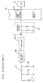
- FIG.7 is a circuit diagram of the preferred embodiment wherein a parallel load resistor 16 is connected across both ends of the pyroelectric sensor 1, and through a coupling circuit consisting of a coupling capacitor 17 and a resistor 18 the signal of the pyroelectric element 1 is led to a low pass filter 19 and further to an amplifier 20.
- the amplified output of the amplifier 20 is rectified by a diode 21 and impressed on a load resistor 25 without smoothing by a smoother circuit.
- Current of a commercial power source 26 is led through a transformer 27 to a clock pulse generator 28 which produces clock pulse train which is in synchronism with the commercial power source current.
- the control circuit 12 comprises: an A/D convertor for converting timings and levels of pulses of input signal to the control part 12 from the rectifier diode 21 into digital signals; a signal width detector 30 for detecting time period of consecutive comings thereto of pulses of levels above a predetermined reference level and issuing digital output signal corresponding to the time period of consecutive comings of the pulses (width of the input pulse); and a comparator 31 which compares digital pulse width data of the signal width detector 30 with a predetermined reference width data.
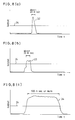
- FIG.8(a), FIG.8(b) and FIG.8(c) show reference level.
- the last output generated by the boiling steam is very much different from the other two kinds of outputs in pulse width. That is the output generated by the boiling steam has a large width of about 500 m sec or longer, while the electric noises generated by the mechanical shock is only about 20 m sec width and the electric noise generated by taking off of the electric plug is about 50 m sec width.
- Output signal 34 of FIG.8(c) from the pyro-electric element 1 is detected by the A/D convertor 29 at every sampling timings t s shown in the waveform SP of FIG.9 by utilizing clock pulses 36 in the waveform CL of FIG.9. And the digital-converted output from the A/D convertor 29 is checked by the signal width detector 30 in the control part 12 of FIG.7, which examines that, when signals above a predetermined level 24 were detected four times or more of the sampling timings, gives "one count” to the comparator 31.
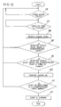
- the sampling timings t s of 37 in the waveform SP of FIG.9 are given at every falls of the synchronization signal 36 which is produced from the commercial power source current 35 in waveform AC of FIG.9 (Step 37).
- Step 38 Output level of signal from the rectifier 21 to the A/D convertor is detected (Step 38).
- the detected output level is compared with a reference level and examined whether it is above a predetermined level (38′). Thereafter, when the output level is above the predetermined level, the length or time period of continuation of the output is examined whether it continues four sampling times (4 t s ) or longer (Step 39). And when the continuation time is four sampling times or longer, the counter in the comparator 31 of the control part 12 make counting (Step 40). And the counted value is examined whether it is equal to a predetermined count (e.g. 10 counts, which corresponds to a time period of about 500 m sec) or not (Step 41).
- a predetermined count e.g. 10 counts, which corresponds to a time period of about 500 m sec
- Step 42 a load-stop signal is issued (Step 42).
- the input signal to the control part 12 is shorter than the predetermined time period of 4 t s as shown by numerals 43 or 44 in the waveform PE of FIG.9, the counter in the comparator 31 does not count, and hence the comparator 31 of the control part 12 does not issue the load-stop signal.
- the output signal above a predetermined level (voltage) is selected and continuation time period of the selected output which is above the reference level is examined of its continuation time period by a timer or the like.
Landscapes
- Physics & Mathematics (AREA)
- General Physics & Mathematics (AREA)
- Engineering & Computer Science (AREA)
- Mathematical Physics (AREA)
- Theoretical Computer Science (AREA)
- Electric Ovens (AREA)
- Control Of High-Frequency Heating Circuits (AREA)
- Investigating Or Analyzing Materials Using Thermal Means (AREA)
- Investigating Or Analyzing Materials By The Use Of Electric Means (AREA)
- Control Of Temperature (AREA)
- Radiation Pyrometers (AREA)
Description
- The present invention relates to an improvement in a pyroelectric sensing apparatus which is for sensing hot steam stream by using a pyroelectric element.
- Hitherto, the signal detection circuits of the pyroelectric element have been configured, for instance as shown in FIG.1. FIG.1 shows an example of a known microwave oven wherein the pyroelectric element is used in a circuit to re-heat a food stuff 8 in the microwave oven. FIG.1 is a sectional schematic view showing the configuration of the microwave oven, wherein in an
metal casing 13 of the microwave oven, a magnetron 3 is mounted on a heating chamber 2. The heating chamber 2 has therein a rotary table 5 for receiving an object food stuff 8 and is to be rotated by amotor 6. A blower 4′ which is driven by a blower motor 4 is provided to blow air for cooling the magnetron 3, and the air heated by the magnetron is led into the heating chamber 2 so as to effectively heat the surface of the food stuff 8. Steam from the heated food stuff 8 is discharged through anexhaust pipe 10 to outside, and a small part of the steam is inhaled through an inhale duct 11 by the function of the blower 4′. The inhale duct 11 has a pyroelectric element 1 therein, so that the part of the steam in the inhaled air touches the active surface of a pyroelectric element 1 mounted on the inhale duct 11. The pyroelectric element 1 has a ferroelectric thin ceramic material on a metal plate, so that its surface electric polarization is changed by local thermal change by the hot steam flow on its surface. - FIG.2(a) and FIG.2(b) elucidate principle of detection of steams by the pyroelectric element 1. The pyroelectric element 1 is made by polarizing a thin ferroelectric film having plumbium titanate and zirconia, or the like ceramic as host material, provided on a metal plate and treated in a strong electric field to make polarization. In a stable state where no steam comes and the sensing face of the pyroelectric element is at a room temperature (T °C), as shown in FIG.2(a) no current flows through an
ammeter 15, because the charges on the polarized surface and the stray charges 14 in the air are making electric neutralization. When a hot steam from the food stuff comes and contacts with a sensing face of the pyroelectric element 1, the hot steam gives iterative local thermal changes ΔT °C to the sensing face of the pyroelectric element, as shown in FIG.2(b). The sensing face of pyroelectric element 1 can not follow such rapid local temperature changes, and therefore the surface of the element makes imbalance of the electric charges, thereby producing pulse train current. The current is detected by the ammeter, and the current is called the pyroelectric current. Referring to Fig. 3, examination of the frequency components of the pulse currents generated by the pyroelectric sensor shows that a 40 dB signal change is generated in a low frequency region (0--4 Hz band) when boiling steam touches the sensor. Line A of FIG.3 shows the sensor output under normal conditions, whereas line B shows the output voltage when the sensor is contacted by steam. - In the conventional circuitry configuration of the pyroelectric sensing apparatus as shown in FIG.4 for detecting the signal of the pyroelectric element 1, a
parallel load resistor 16 is connected across both ends of the pyroelectric sensor 1, and through a coupling circuit consisting of acoupling capacitor 17 and aresistor 18 the signal of the pyroelectric element 1 is led to alow pass filter 19 and further to anamplifier 20. The amplified signal is then rectified by adiode 21 and smoothed by asmoother circuit 22. Then the smoothed output led to acontrol circuit 12, which have acomparison circuit 23 for comparing the input level of smoothed DC signal with a reference level. Output of thecontrol circuit 12, which is based on the output of thecomparison circuit 23, is given to aload machine 13 to be controlled, so that, when the input to thecontrol circuit 12 exceeds a predetermined level, an interruption switch is activated, thereby to stop the oscillation of the magnetron. - FIG.5 shows a time chart of the input voltage to the
control circuit 12 from thesmoother circuit 22, wherein vertical dotted lines A show original output pulses of the pyroelectric sensor 1 and solid line curve B shows output of thesmoother circuit 22. The conventional microwave oven is configurated such that thecontrol circuit 12 stops the oscillation of the magnetron 3 when output signal level of thesmoother circuit 22 exceeds thepredetermined reference level 24, thereby to prevent over-heating of the food stuff. - The above-mentioned conventional apparatus, however, has a problem that when a strong mechanical shock, such as one generated by closing of a door of the microwave oven often causes the pyroelectric element 1 to generate a strong electric pulse induced by mechanical strain of the pyroelectric element, as shown in FIG.6, wherein a pulse C corresponds to the occurrence of the door shock. Such strong electric pulse in the output will undesirably causes the control circuit to actuate the load interruption switch, and erroneously stops the oscillation of the magnetron. That is, the conventional pyroelectric sensor circuitry has a problem of erroneous operation at mechanical shocks.
- EP-A-0198430 discloses a heating apparatus in which a piezoelectric device sensor is provided in an exhaust passage for detecting heating condition of an object such as food in a microwave oven heating chamber. The output signal from the piezoelectric device sensor is processed so that only particular frequency components lower than that of a commercial AC supply are amplified and then compared with the threshold value.
- In order to dissolve the above-mentioned problem of maloperation as a steam detection element, the pyroelectric sensing apparatus in accordance with the present invention has an improved configuration.
- The pyroelectric sensing apparatus in accordance with the present invention is defined by the feature of claim 1. The precharacterizing features of claim 1 correspond to the prior art shown in Figures 1 to 5 which has been already discussed above.
- The pyroelectric sensing apparatus in accordance with the present invention can make accurate and reliable signal detection because of high SN ratio, since short width noise outputs issued by mechanical shock or electric shock are prevented from producing the load-stop signal, by taking advantage of the characteristic of the pyroelectric detection signal of boiling steam having low frequency components.
- Furthermore, the pyroelectric sensing apparatus of the present invention enables the accurate detection of the boiling steam, without any delaying which has been in the conventional analog circuit using the capacitor smoothing circuit. Hence a very quick generation of load-stop signal is possible owing to use of the digital circuit.
- By the above-mentioned configuration, the pyroelectric sensing apparatus in accordance with the present invention issues output signal only at detection of steam, discriminating it from spurious noise due to mechanical shock impressed thereon.
- While the novel features of the invention are set forth particularly in the appended claims, the invention, both as to organization and content, will be better understood and appreciated, along with other objects and features thereof, from the following detailed description taken in conjunction with the drawings.
-
- FIG.1 is a schematic vertical view showing configuration of a known electric oven wherein the pyroelectric sensing apparatus both of the conventional and the present invention are provided.
- FIG. 2(a) and FIG. 2(b) are schematic circuit diagram for explanation of operation principle of the pyroelectric sensing element.
- FIG.3 is a frequency spectrum graph showing frequency components of electric output of a pyroelectric element at contact by boiling steam thereon.
- FIG.4 is a circuit diagram of the conventional pyroelectric sensing apparatus.
- FIG.5 is a time chart of smoothed output voltage of a pyroelectric element in ordinary operation.
- FIG.6 is a time chart of smoothed output voltage of a pyroelectric element at impression of a mechanical shock thereon.
- FIG.7 is a circuit diagram of a preferred embodiment of the present invention.
- FIG.8(a), FIG.8(b) and FIG.8(c) are waveforms of output of the smoothed pyroelectric elements in various states.
- FIG.9 is a time chart of signals of various parts of the circuit of FIG. 7.
- FIG.10 is a flow chart showing algorithm of
control part 12 of the circuit of FIG.7. - A preferred embodiment of the present invention is elucidated with reference to FIG.7 and thereafter. FIG.7 is a circuit diagram of the preferred embodiment wherein a
parallel load resistor 16 is connected across both ends of the pyroelectric sensor 1, and through a coupling circuit consisting of acoupling capacitor 17 and aresistor 18 the signal of the pyroelectric element 1 is led to alow pass filter 19 and further to anamplifier 20. The amplified output of theamplifier 20 is rectified by adiode 21 and impressed on aload resistor 25 without smoothing by a smoother circuit. Current of acommercial power source 26 is led through atransformer 27 to aclock pulse generator 28 which produces clock pulse train which is in synchronism with the commercial power source current. Thecontrol circuit 12 comprises: an A/D convertor for converting timings and levels of pulses of input signal to thecontrol part 12 from therectifier diode 21 into digital signals; asignal width detector 30 for detecting time period of consecutive comings thereto of pulses of levels above a predetermined reference level and issuing digital output signal corresponding to the time period of consecutive comings of the pulses (width of the input pulse); and acomparator 31 which compares digital pulse width data of thesignal width detector 30 with a predetermined reference width data. - Next, principle of operation of the embodiment of FIG.7 is elucidated with reference to time charts shown in FIG.8(a), FIG.8(b) and FIG.8(c). Among the output signal of the pyroelectric element 1, there are mainly three kinds of outputs, namely an output generated by mechanical shock such as open or close of the microwave oven as shown by
numeral 32 of FIG.8(a), another output generated by pulling out electric plug from a wall consent of the common power line with the microwave oven as shown bynumeral 33 in FIG.8(b), and still another output generated by coming of boiling steam on the sensing face of the pyroelectric sensor as shown bynumeral 34 in FIG.8(c). FIGS. 8(a), 8(b) and 8(c)lines 24 show reference level. By comparing these three kinds of output, it is observed that the last output generated by the boiling steam is very much different from the other two kinds of outputs in pulse width. That is the output generated by the boiling steam has a large width of about 500 m sec or longer, while the electric noises generated by the mechanical shock is only about 20 m sec width and the electric noise generated by taking off of the electric plug is about 50 m sec width. - Therefore, the above-mentioned difference of electric output is utilized in selecting the genuine signal by boiling steam and producing load controlling signal in the circuit of FIG.7.
- The operation of the embodiment circuit of FIG.7 is elucidated with reference to the electric waveforms shown in FIG.9 together with a control flow chart of FIG.10.
-
Output signal 34 of FIG.8(c) from the pyro-electric element 1 is detected by the A/D convertor 29 at every sampling timings ts shown in the waveform SP of FIG.9 by utilizingclock pulses 36 in the waveform CL of FIG.9. And the digital-converted output from the A/D convertor 29 is checked by thesignal width detector 30 in thecontrol part 12 of FIG.7, which examines that, when signals above apredetermined level 24 were detected four times or more of the sampling timings, gives "one count" to thecomparator 31. The sampling timings ts of 37 in the waveform SP of FIG.9 are given at every falls of thesynchronization signal 36 which is produced from the commercial power source current 35 in waveform AC of FIG.9 (Step 37). Output level of signal from therectifier 21 to the A/D convertor is detected (Step 38). Next, the detected output level is compared with a reference level and examined whether it is above a predetermined level (38′). Thereafter, when the output level is above the predetermined level, the length or time period of continuation of the output is examined whether it continues four sampling times (4 ts) or longer (Step 39). And when the continuation time is four sampling times or longer, the counter in thecomparator 31 of thecontrol part 12 make counting (Step 40). And the counted value is examined whether it is equal to a predetermined count (e.g. 10 counts, which corresponds to a time period of about 500 m sec) or not (Step 41). den the counted value reaches equal to the predetermined count, a load-stop signal is issued (Step 42). In other words, when the input signal to thecontrol part 12 is shorter than the predetermined time period of 4 ts as shown bynumerals 43 or 44 in the waveform PE of FIG.9, the counter in thecomparator 31 does not count, and hence thecomparator 31 of thecontrol part 12 does not issue the load-stop signal. - A part from the above-mentioned embodiment wherein the load-stop signal is generated when the output from the pyroelectric element continues longer than a predetermined time period e.g. four sampling times or more, other modified manner of checking the output of the pyroelectric element is possible. In such modified manner, the output signal above a predetermined level (voltage) is selected and continuation time period of the selected output which is above the reference level is examined of its continuation time period by a timer or the like.
Claims (3)
- A pyroelectric sensing apparatus comprising:
a pyroelectric element (1) which issues succession of pulses when steam contacts its sensing face,
low pass filter means (19) for filtering selected mode of succession of pulses, and
detection means (29) for detecting filtered pulses, which are above a predetermined level (24), characterized in that
said detection means (29) are provided for detecting said filtered pulses by sampling with predetermined sampling timings,
succession period detection means (30) are provided for detecting time period between consecutive pulses detected by said detection means (29) as being above said predetermined level, and
comparison means (31) are provided for comparing time period detected by said succession period detection means with a predetermined reference time period and issues a control output signal when said detected time period is longer than said reference time period. - A pyroelectric sensing apparatus in accordance with claim 1, wherein
said predetermined sampling time is defined by clock pulses (36) produced from an AC current of a commercial power source (26). - A pyroelectric sensing apparatus in accordance with claim 1, wherein
said predetermined reference time period is substantially 500 m sec.
Applications Claiming Priority (2)
| Application Number | Priority Date | Filing Date | Title |
|---|---|---|---|
| JP63274836A JPH0820910B2 (en) | 1988-10-31 | 1988-10-31 | Piezoelectric element applied sensor |
| JP274836/88 | 1988-10-31 |
Publications (3)
| Publication Number | Publication Date |
|---|---|
| EP0367186A2 EP0367186A2 (en) | 1990-05-09 |
| EP0367186A3 EP0367186A3 (en) | 1991-08-21 |
| EP0367186B1 true EP0367186B1 (en) | 1995-01-11 |
Family
ID=17547262
Family Applications (1)
| Application Number | Title | Priority Date | Filing Date |
|---|---|---|---|
| EP89120112A Expired - Lifetime EP0367186B1 (en) | 1988-10-31 | 1989-10-30 | Pyroelectric sensing apparatus |
Country Status (7)
| Country | Link |
|---|---|
| US (1) | US5051701A (en) |
| EP (1) | EP0367186B1 (en) |
| JP (1) | JPH0820910B2 (en) |
| KR (1) | KR930006303B1 (en) |
| AU (1) | AU603304B2 (en) |
| CA (1) | CA2001652C (en) |
| DE (1) | DE68920550T2 (en) |
Families Citing this family (11)
| Publication number | Priority date | Publication date | Assignee | Title |
|---|---|---|---|---|
| US5235148A (en) * | 1989-04-19 | 1993-08-10 | Matsushita Electric Industrial Co., Ltd. | Heating apparatus |
| JP2584053B2 (en) * | 1989-04-19 | 1997-02-19 | 松下電器産業株式会社 | Automatic heating device |
| US5228114A (en) * | 1990-10-30 | 1993-07-13 | Tokyo Electron Sagami Limited | Heat-treating apparatus with batch scheme having improved heat controlling capability |
| DE4111551A1 (en) * | 1991-04-09 | 1992-10-15 | Schaeffler Waelzlager Kg | Linear guide unit with elongated U=shaped guide housing - has axially parallel guide rail, with carriage and drive mechanism |
| JPH08186448A (en) * | 1994-10-31 | 1996-07-16 | Sharp Corp | FM demodulator |
| EP0939311B1 (en) * | 1998-02-27 | 2011-02-09 | Panasonic Electric Works Co., Ltd. | Infrared-rays detector |
| DE10046522C1 (en) * | 2000-09-15 | 2002-08-01 | Siemens Ag | Device for detecting the operating temperature of a winding |
| EP2807902B1 (en) * | 2012-01-23 | 2020-08-19 | CONNORS, Robert W. | Compact microwave oven |
| US20160238452A1 (en) * | 2014-04-15 | 2016-08-18 | Shuza Binzaid | Pyroelectric reference device for micro-power harvesting and sensor applications |
| CN109442502B (en) * | 2018-10-11 | 2020-02-04 | 珠海格力电器股份有限公司 | Electromagnetic heating device power adjusting system, electromagnetic heating device and adjusting method |
| CN112564547A (en) * | 2020-12-01 | 2021-03-26 | 西安交通大学 | Vibration slapping contact type waste heat pyroelectric energy acquisition device and method |
Family Cites Families (8)
| Publication number | Priority date | Publication date | Assignee | Title |
|---|---|---|---|---|
| GB1066752A (en) * | 1964-04-28 | 1967-04-26 | Matsushita Electric Industrial Co Ltd | Piezoelectric ceramic compositions |
| CA1147036A (en) * | 1978-09-26 | 1983-05-24 | Shigeru Kusunoki | Method of controlling heating in food heating apparatus including infrared detecting system |
| DE3066593D1 (en) * | 1979-08-17 | 1984-03-22 | Matsushita Electric Industrial Co Ltd | Heating apparatus with sensor |
| JPS5691716A (en) * | 1979-12-24 | 1981-07-24 | Matsushita Electric Industrial Co Ltd | Automatic electronic range |
| JPS6234166Y2 (en) * | 1980-07-28 | 1987-09-01 | ||
| EP0078325B1 (en) * | 1981-05-13 | 1986-12-17 | Matsushita Electric Industrial Co., Ltd. | Heating device |
| CA1199076A (en) * | 1981-07-06 | 1986-01-07 | Takeshi Tanabe | Microwave heating appliance with simplified user's operation |
| JPH06103103B2 (en) * | 1985-04-11 | 1994-12-14 | 松下電器産業株式会社 | Microwave oven with piezoelectric element sensor |
-
1988
- 1988-10-31 JP JP63274836A patent/JPH0820910B2/en not_active Expired - Lifetime
-
1989
- 1989-10-30 DE DE68920550T patent/DE68920550T2/en not_active Expired - Lifetime
- 1989-10-30 AU AU43861/89A patent/AU603304B2/en not_active Ceased
- 1989-10-30 CA CA002001652A patent/CA2001652C/en not_active Expired - Lifetime
- 1989-10-30 EP EP89120112A patent/EP0367186B1/en not_active Expired - Lifetime
- 1989-10-31 US US07/429,286 patent/US5051701A/en not_active Expired - Lifetime
- 1989-10-31 KR KR1019890015770A patent/KR930006303B1/en not_active Expired - Lifetime
Also Published As
| Publication number | Publication date |
|---|---|
| DE68920550D1 (en) | 1995-02-23 |
| KR930006303B1 (en) | 1993-07-12 |
| EP0367186A2 (en) | 1990-05-09 |
| CA2001652C (en) | 1994-03-08 |
| AU603304B2 (en) | 1990-11-08 |
| KR900006767A (en) | 1990-05-08 |
| EP0367186A3 (en) | 1991-08-21 |
| US5051701A (en) | 1991-09-24 |
| AU4386189A (en) | 1990-05-03 |
| CA2001652A1 (en) | 1990-04-30 |
| DE68920550T2 (en) | 1995-10-05 |
| JPH0820910B2 (en) | 1996-03-04 |
| JPH02120914A (en) | 1990-05-08 |
Similar Documents
| Publication | Publication Date | Title |
|---|---|---|
| US5051701A (en) | Pyroelectric sensing apparatus substantially independent of noise output caused by mechanical shock or electrical shock | |
| US4335293A (en) | Heating control apparatus by humidity detection | |
| US4672180A (en) | Heating apparatus with piezoelectric device sensor | |
| WO2001051894A1 (en) | Circuitry for signal measurement | |
| WO1983001675A1 (en) | High frequency heating device | |
| KR940000252B1 (en) | Noise Canceling Telemetry Receiver | |
| JP2507004B2 (en) | Piezoelectric element applied sensor device | |
| WO1990009139A1 (en) | Arrangement for a vacuum cleaner | |
| JPH0355435A (en) | Heating apparatus and controlling method therefor | |
| JPH0665145B2 (en) | Induction heating cooker | |
| KR940004048B1 (en) | Spark prevention circuit of microwave oven and method | |
| JPS59194385A (en) | Controller of electronic range | |
| JPS621757Y2 (en) | ||
| KR0133414B1 (en) | Automatic cooking method and apparatus of microwave oven | |
| KR890001656Y1 (en) | Temperatur difference detector device | |
| JPH0654356B2 (en) | Hot wire detector | |
| JPS594226A (en) | Analog voltage processing device | |
| KR950005103A (en) | Instantaneous blackout detection circuit of high frequency heating device | |
| KR920004323B1 (en) | Cooking method of microwave oven | |
| SU631963A1 (en) | Alarm | |
| JP2917667B2 (en) | Ring tone signal detection circuit | |
| JPH02120913A (en) | Piezoelectric element applied sensor | |
| JPS61161925A (en) | Commercial power frequency discrimination device | |
| JPH01267995A (en) | Heating device | |
| KR930001752A (en) | Automatic heating device of microwave oven using pyroelectric sensor |
Legal Events
| Date | Code | Title | Description |
|---|---|---|---|
| PUAI | Public reference made under article 153(3) epc to a published international application that has entered the european phase |
Free format text: ORIGINAL CODE: 0009012 |
|
| 17P | Request for examination filed |
Effective date: 19891030 |
|
| AK | Designated contracting states |
Kind code of ref document: A2 Designated state(s): DE FR GB IT SE |
|
| PUAL | Search report despatched |
Free format text: ORIGINAL CODE: 0009013 |
|
| AK | Designated contracting states |
Kind code of ref document: A3 Designated state(s): DE FR GB IT SE |
|
| 17Q | First examination report despatched |
Effective date: 19930817 |
|
| GRAA | (expected) grant |
Free format text: ORIGINAL CODE: 0009210 |
|
| AK | Designated contracting states |
Kind code of ref document: B1 Designated state(s): DE FR GB IT SE |
|
| ITF | It: translation for a ep patent filed | ||
| EAL | Se: european patent in force in sweden |
Ref document number: 89120112.1 |
|
| REF | Corresponds to: |
Ref document number: 68920550 Country of ref document: DE Date of ref document: 19950223 |
|
| ET | Fr: translation filed | ||
| PLBE | No opposition filed within time limit |
Free format text: ORIGINAL CODE: 0009261 |
|
| STAA | Information on the status of an ep patent application or granted ep patent |
Free format text: STATUS: NO OPPOSITION FILED WITHIN TIME LIMIT |
|
| 26N | No opposition filed | ||
| REG | Reference to a national code |
Ref country code: GB Ref legal event code: 746 Effective date: 19970901 |
|
| REG | Reference to a national code |
Ref country code: GB Ref legal event code: IF02 |
|
| PGFP | Annual fee paid to national office [announced via postgrant information from national office to epo] |
Ref country code: IT Payment date: 20061031 Year of fee payment: 18 |
|
| PGFP | Annual fee paid to national office [announced via postgrant information from national office to epo] |
Ref country code: DE Payment date: 20081027 Year of fee payment: 20 |
|
| PGFP | Annual fee paid to national office [announced via postgrant information from national office to epo] |
Ref country code: SE Payment date: 20081022 Year of fee payment: 20 |
|
| PGFP | Annual fee paid to national office [announced via postgrant information from national office to epo] |
Ref country code: FR Payment date: 20081014 Year of fee payment: 20 |
|
| PGFP | Annual fee paid to national office [announced via postgrant information from national office to epo] |
Ref country code: GB Payment date: 20081029 Year of fee payment: 20 |
|
| PG25 | Lapsed in a contracting state [announced via postgrant information from national office to epo] |
Ref country code: IT Free format text: LAPSE BECAUSE OF NON-PAYMENT OF DUE FEES Effective date: 20071030 |
|
| REG | Reference to a national code |
Ref country code: GB Ref legal event code: PE20 Expiry date: 20091029 |
|
| EUG | Se: european patent has lapsed | ||
| PG25 | Lapsed in a contracting state [announced via postgrant information from national office to epo] |
Ref country code: GB Free format text: LAPSE BECAUSE OF EXPIRATION OF PROTECTION Effective date: 20091029 |