EP0367139A2 - Injection moulding machine and method of regulating the clamping force of an injection moulding machine - Google Patents
Injection moulding machine and method of regulating the clamping force of an injection moulding machine Download PDFInfo
- Publication number
- EP0367139A2 EP0367139A2 EP89119989A EP89119989A EP0367139A2 EP 0367139 A2 EP0367139 A2 EP 0367139A2 EP 89119989 A EP89119989 A EP 89119989A EP 89119989 A EP89119989 A EP 89119989A EP 0367139 A2 EP0367139 A2 EP 0367139A2
- Authority
- EP
- European Patent Office
- Prior art keywords
- clamp
- pressure
- clamping force
- hydraulic
- actual
- Prior art date
- Legal status (The legal status is an assumption and is not a legal conclusion. Google has not performed a legal analysis and makes no representation as to the accuracy of the status listed.)
- Withdrawn
Links
Images
Classifications
-
- B—PERFORMING OPERATIONS; TRANSPORTING
- B29—WORKING OF PLASTICS; WORKING OF SUBSTANCES IN A PLASTIC STATE IN GENERAL
- B29C—SHAPING OR JOINING OF PLASTICS; SHAPING OF MATERIAL IN A PLASTIC STATE, NOT OTHERWISE PROVIDED FOR; AFTER-TREATMENT OF THE SHAPED PRODUCTS, e.g. REPAIRING
- B29C45/00—Injection moulding, i.e. forcing the required volume of moulding material through a nozzle into a closed mould; Apparatus therefor
- B29C45/17—Component parts, details or accessories; Auxiliary operations
- B29C45/76—Measuring, controlling or regulating
- B29C45/7653—Measuring, controlling or regulating mould clamping forces
-
- B—PERFORMING OPERATIONS; TRANSPORTING
- B29—WORKING OF PLASTICS; WORKING OF SUBSTANCES IN A PLASTIC STATE IN GENERAL
- B29C—SHAPING OR JOINING OF PLASTICS; SHAPING OF MATERIAL IN A PLASTIC STATE, NOT OTHERWISE PROVIDED FOR; AFTER-TREATMENT OF THE SHAPED PRODUCTS, e.g. REPAIRING
- B29C45/00—Injection moulding, i.e. forcing the required volume of moulding material through a nozzle into a closed mould; Apparatus therefor
- B29C45/17—Component parts, details or accessories; Auxiliary operations
- B29C45/64—Mould opening, closing or clamping devices
- B29C45/67—Mould opening, closing or clamping devices hydraulic
Definitions
- This invention relates to an improved method and apparatus for providing a desired hydraulic clamping pressure in an hydraulically operated clamping press. More particularly, the present invention relates to a method and apparatus for controlling the clamping force exerted by the mold clamping system of an injection molding machine in order to provide a mold closing force that corresponds with a predetermined mold closing force, so that plastic material injected into the mold under high pressure does not flash from the mold as a result of mold separation during the injection step.
- Injection molding machines include a plastication and injection unit for converting solid polymeric material from solid pellets to a flowable liquid that can be injected under pressure into a closed mold cavity in order to completely fill the mold cavity and provide the desired molded article.
- the mold in which the desired article is formed is typically a multiple part mold, which could be as few as two parts, that is adapted to be closed while the polymeric material is being injected into the cavity defined by the mold parts when they are in contact with each other, and which is then adapted to be opened, by separating the mold parts, in order to permit removal of the molded article.
- Such machines include apparatus for moving the mold parts into and out of engagement with each other, and also include a clamping arrangement that is intended to apply a clamping force to hold the molds in tightly engaged relationship while the injection of the polymeric material is taking place.
- injection pressures can typically range in the thousands of pounds per square inch, and when that pressure is exerted within the closed mold cavity, the pressure acts on the mold cavity surfaces with a resultant force that tends to urge the mold parts apart from each other.
- clamping apparatus for holding the mold parts tightly together to prevent such separation, and typically the clamping apparatus includes an hydraulically operated clamp that is capable of providing high clamping forces on the mold halves, the magnitude of the forces depending upon the sizes of the mold cavities and on the areas of the surfaces over which the pressure of the injected plastic material acts.
- Injection molding machines are presently commercially available that are capable of providing clamping forces as large as 1,000 tons and more.
- hydraulic clamp force maintenance apparatus in an injection molding machine that includes an hydraulic clamp cylinder and piston slidably carried in the cylinder for applying and maintaining a clamping force on a multiple part, separable mold, in order to maintain the mold parts in a closed condition as plastic material is being injected into the mold cavity at a high pressure.
- the apparatus includes a pressurizing means for providing hydraulic fluid under pressure to the clamp cylinder and valve means positioned between the pressurizing means and the clamp cylinder, the valve means being operable selectively between an open position to permit flow of pressurized fluid from the pressurizing means to the clamp cylinder, and a closed position to prevent flow of hydraulic fluid from the clamp cylinder in order to maintain hydraulic fluid under pressure within the clamp cylinder.
- a pressure transducer is provided in communication with the hydraulic cylinder for providing an output signal representative of the hydraulic fluid pressure within the cylinder.
- Set point setting means are provided for setting a predetermined set point clamping force value
- comparator means are connected with the pressure transducer means and with the set point setting means for comparing the output signal of the pressure transducer means during a clamp force maintenance portion of a clamp operating cycle, with the set point clamping force value to provide a correction signal representative of the difference between the clamping force represented by the transducer output signal and the set point clamping force value.
- Control means are connected with the comparator means and with the valve means to provide a control signal for regulating the opening and closing of the valve means during the next succeeding clamp operating cycle in order to provide a clamping force during the clamp force maintenance portion of that next succeeding cycle that is closer to the set point clamping force value than was the clamping force in the immediately preceding clamp operating cycle.
- a method for regulating the clamping force in an hydraulic clamp cylinder of an injection molding machine.
- the method includes the step of providing a clamping force set point value corresponding with a desired clamping force to be imposed by a clamp hydraulic cylinder during a clamp force maintenance portion of a clamp operating cycle.
- a desired clamp cylinder hydraulic pressure value is determined to correspond with the desired clamping force value, and the actual hydraulic pressure in the hydraulic clamp cylinder during a first clamp operating cycle is sensed to provide a clamping pressure signal representative of the actual clamp cylinder hydraulic pressure during the clamp force maintenance portion of the clamp operating cycle.
- the sensed clamping pressure is compared with the desired clamping pressure, which is based upon the desired clamping force, to provide a signal representative of the difference between the two pressures.
- the time of closing of a flow control valve connected with the clamp hydraulic cylinder is controlled during the next succeeding clamp operating cycle as a function of the pressure difference and the pressure in the clamping cylinder at the time of closing of the flow control valve during the preceding clamp operating cycle. At least a part of the pressure difference is added to the pressure value at which the valve was closed during the preceding cycle in order to provide a clamping force that is closer to the desired clamping force.
- a stationary platen 12 is carried by a base (not shown) and securely supports a first, stationary mold half 14.
- Stationary platen 12 also supports a pair of rapid traverse cylinders 16 within which respective pistons 18 are movable and from which respective piston rods 20 extend in an outward direction beyond stationary mold half 14.
- a movable platen 22 is positioned opposite and facing stationary platen 12 and carries a second, movable mold half 24 on face 26 thereof. Mold half 24 is adapted to engage with stationary mold half 14 to define therebetween one or more mold cavities (not shown).
- Movable platen 22 is slidably carried on a plurality of spaced, parallel tie rods (not shown) that can be connected to stationary platen 12 to extend outwardly therefrom toward and beyond movable platen 22, so that movable platen 22 can be moved toward and away from stationary platen 12.
- Piston rods 20 of rapid traverse cylinders 16 are connected with movable platen 22, and the cylinders are adapted to quickly move movable platen 22 either toward or away from stationary platen 12 during the operating cycle of the machine.
- a clamp piston 30 Extending from opposite face 28 of movable platen 22 is a clamp piston 30 that is slidably carried in a sleeve-like clamp cylinder 32 that has an open end 34 and a closed end 36.
- Open end 34 faces movable platen 22 and closed end 36 includes a flow control valve 38, commonly referred to as a prefill valve, that is adapted to permit the flow of hydraulic fluid into and out of the clamp cylinder from and to reservoir 40.
- a flow control valve 38 commonly referred to as a prefill valve
- Pressurizing fluid for clamp cylinder 32 is obtained from a pressurizing system that includes an hydraulic pump 42, the output of which is conveyed through a pump conduit 44 to a second flow control valve 46 and then through clamp cylinder conduit 48.
- flow control valve 46 is a zero-leakage, cartridge-type valve that tightly seals the fluid pathway between pump conduit 44 and clamp cylinder conduit 48 to minimize leakage from the clamp cylinder and thereby maintain the desired hydraulic pressure level in the clamp cylinder.
- a pressure transducer 50 is provided in clamp cylinder conduit 48 to sense the hydraulic pressure within clamp cylinder 32 and to provide an output signal representative of that hydraulic pressure.
- the output of pump 42 can also be in communication with another system 52, which is designated schematically in the drawing, and which can be, for example, the injection system or any other system of the machine in which hydraulic fluid under pressure is required during the time valve 46 is closed.
- another system 52 which is designated schematically in the drawing, and which can be, for example, the injection system or any other system of the machine in which hydraulic fluid under pressure is required during the time valve 46 is closed.
- valve 46 is in the form of an assembly that includes a directional flow control valve 54, a cover cartridge 56, and a cartridge valve 58, and can be a commercially available valve structure that is obtainable from Rexroth Corp., of Bethelhem, Pennsylvania. Although a particular type of cartridge valve structure has been illustrated and described, it will be apparent to those skilled in the art that other types of valves can be provided, if desired, to perform the same function as that of the cartridge valve structure disclosed herein.
- the pressure transducer can be of any convenient and suitable type, such as, for example, a strain gage-type transducer, a piezoelectric transducer, or the like.
- a suitable pressure transducer can be obtained from Dynisco Inc., of Norwood, Massachusetts.
- injection barrel 60 The source of the plasticated material that is injected into the mold cavity is the injection system, of which only a fragmentary representation of an injection barrel 60 is shown in Figure 1.
- Injection barrel 60 is positioned on the opposite side of stationary platen 12 from that on which stationary mold half 14 is secured, and it includes an outlet that communicates with a passageway (not shown) that extends through stationary platen 12 and stationary mold half 14 to communicate with the mold cavity.
- the clamping system shown operates from an initial position in which mold halves 12 and 24 are spaced from each other, which could result from the withdrawal from the mold cavity of a molded article that was molded in the preceding cycle. Mold halves 12 and 24 are closed by applying hydraulic pressure on the rod end of each of rapid traverse cylinders 16, which causes movable platen 22, along with movable mold half 24, to travel along the tie rods (not shown) toward stationary platen 12 and stationary mold half 14.
- the direction of movement is from right to left as viewed in Figure 1, and the position of the parts as illustrated in Figure 1 shows the mold halves 12 and 24 in cooperative engagement.
- clamp piston 30, which is secured thereto, moves along with it, outwardly from clamp cylinder 32 and in a direction away from prefill valve 38.
- prefill valve 38 is opened so that hydraulic fluid from reservoir 40 can flow through the prefill valve to occupy the space vacated by the outwardly moving piston and thereby fill the increasing volume of the clamp cylinder with hydraulic fluid.
- valve 46 When movable platen 22 has reached substantially its furthest position relative to clamp cylinder 32, and is in the position shown in Figure 1, at which point mold halves 14 and 24 are substantially in contacting engagement, prefill valve 38 is closed, valve 46 is opened, and pump 42 is energized to provide pressurized hydraulic fluid through pump conduit 44, valve 46, and clamp cylinder conduit 48 in order to impose pressure on the hydraulic fluid within the clamp cylinder, and thereby provide a clamping force to hold the two mold halves together while high pressure plasticated material is being injected into the mold cavity.
- valve 46 can be closed by a control signal provided by a control system, which will be hereinafter described.
- valve 46 When valve 46 is closed, the fact that substantially no leakage occurs through the valve means that the pressure within clamp cylinder 32 is maintained until the hydraulic pressure in clamp cylinder 32 is released by a suitable decompression valve 39, which can be, for example, a pilot operated counterbalance valve to control the rate of release of the hydraulic pressure in the clamp cylinder.
- a suitable decompression valve 39 can be, for example, a pilot operated counterbalance valve to control the rate of release of the hydraulic pressure in the clamp cylinder.
- pump 42 is not needed for maintaining the clamping force, and consequently the pump can either be shut down, or its output diverted to another system, such as, for example, the injection system 52, which comes into play while the clamping force is being maintained on the mold halves.
- the mold halves are maintained together for a short period of time while the plasticated material in the mold cavity is allowed to cool and solidify.
- the pressure maintained in clamp cylinder 32 by valve 46 is released by opening decompression valve 39, after which prefill valve 38 is opened, and rapid traverse cylinders 16 are activated by providing pressurized hydraulic fluid at the head end of each of cylinders 16 to force the platens and mold halves apart, and to shift movable platen 22 toward clamp cylinder 32 in order to permit the molded article to be removed from the mold cavity. After removal of the molded part the cycle is repeated.
- Pressure transducer 50 senses the hydraulic pressure within clamp cylinder 32 and can be used to provide an output signal when the desired hydraulic pressure is reached.
- time delays in the system including the time required to actuate valve 46 to move the valve spool from an open to a closed condition, in practical effect the hydraulic pressure within the clamp cylinder continues to rise to a level above the desired pressure as a result of overshoot resulting from those time delays.
- the hydraulic pressure, and consequently the clamping force will be higher than the desired value, which could cause damage to the mold halves, and possibly also to the injection molding machine, if the pressure were excessively high.
- the present invention provides a control arrangement for correcting for the overshoot in a given operating cycle by applying a correction factor during the subsequent operating cycle in order to provide a clamp cylinder hydraulic pressure that results in the desired clamping force between the mold halves.
- pump 42 operates through control valve 46 to provide pressurized hydraulic fluid to clamp cylinder 32.
- the pressure within clamp cylinder 32 is sensed by pressure transducer 50, which provides an output signal representative of the clamp cylinder hydraulic pressure.
- the output signal changes in magnitude as the hydraulic pressure within clamp cylinder builds up as a result of the operation of pump 42, and when the desired pressure level is reached control valve 46 is closed.
- the steady-state pressure value in the clamp cylinder during the clamping phase of the cycle is higher than the desired pressure.
- the output signal corresponding with that steady-state value is provided to a comparator 70, into which the desired clamping force signal is also entered.
- the desired clamping force signal can be converted within the comparator to a pressure value by dividing the clamping force by the transverse cross-sectional area of the clamping piston against which the hydraulic pressure acts.
- Comparator 70 compares the pressure value corresponding with the desired clamping force with the measured steady-state clamp cylinder hydraulic pressure, which is in the form of the steady-state output signal from the pressure transducer, and subtracts that measured clamp hydraulic pressure from the desired hydraulic pressure to provide a pressure difference signal.
- the pressure difference signal is provided as an input to a control unit 72 that subsequently provides an output control signal that is representative of a new pressure level for use in the next succeeding clamp operating cycle to close control valve 46 at the proper part of the next succeeding clamp operating cycle. In that next cycle the clamp hydraulic pressure is continuously monitored by the pressure transducer, and when the new pressure level is reached the control unit sends a control signal to close the control valve.
- the control signal from the control unit is the algebraic sum of the steady-state clamp hydraulic pressure as measured during the preceding cycle and the pressure difference signal based upon the operation of the clamp system during that preceding cycle.
- the pressure difference signal can be either a positive or a negative quantity, depending upon the measured steady-state clamp hydraulic pressure in the initial operating cycle.
- a suitable control signal is applied to decompression valve 39 to thereby release the pressure in clamp cylinder 32, whereupon the prefill valve is opened and the clamp piston is again retracted into the clamp cylinder.
- control unit 72 provides an output signal indicative of that changing pressure level to control unit 72.
- control unit 72 provides a control signal to close control valve 46 in order to attempt to obtain a corrected hydraulic pressure within clamp cylinder 32.
- the control arrangement in accordance with the present invention operates to sense operating parameters to determine the difference between the actual clamping force relative to the desired clamping force during a given clamp operating cycle, and then provides a correction signal to attempt to control the operation of the control valve so that the valve is closed either earlier or later than it had been closed in the preceding cycle, in order to correct the clamping force during the next operating cycle by either reducing the hydraulic pressure in the clamp cylinder or by increasing it.
- control arrangement illustrated in Figure 2 can be achieved by separate components that provide the particular functions illustrated and described. Additionally, however, if desired a microprocessor can be provided to perform the functions of the comparator and the control unit as hereinbefore described.
- FIG. 3 there is shown a flow chart for the preferred embodiment of the invention and illustrating the various steps to provide the desired hydraulic pressure in the clamping cylinder.
- the system is started by entering a desired clamping force signal at step 80.
- the desired clamping force is determined by the machine user and is usually based upon the injection pressure to be utilized to inject the plasticated material into the mold and the projected area of the mold cavity over which that pressure will act.
- the desired hydraulic pressure that corresponds with the desired clamping force is calculated at step 82, based upon the cross-sectional area of the clamping piston, to provide a set point or desired pressure value P D .
- step 84 the control unit closes the control valve when the desired pressure P D is reached, as sensed by the pressure transducer.
- the actual steady-state clamping pressure within the clamping cylinder is usually greater than the desired pressure by virtue of the overshoot of the pressure level resulting from time delays in the hydraulic system.
- the actual hydraulic pressure within the cylinder would be less than the desired value.
- the pressure transducer senses the hydraulic pressure within the clamping cylinder, and after the control valve has closed and the pressure within the clamp cylinder has reached a steady-state value, that steady-state value is considered in step 86 to be the actual hydraulic clamping pressure P A within the clamping cylinder. That actual hydraulic clamping pressure P A is compared with the desired hydraulic clamping pressure P D , and if the two pressures are different the actual pressure is subtracted from the desired pressure in step 88 to provide a pressure difference signal P.
- the magnitude of the pressure difference determined in step 88 affects the amount of pressure level correction that is used to set the clamp hydraulic pressure control signal to be provided in the next succeeding operating cycle. If it is determined in step 90 that the absolute value of the pressure difference P is less than a predetermined value, which, for example, can be selected to be 30 tons for an injection molding machine having a clamp system providing a maximum clamping force of 250 tons, then only a portion of that pressure difference is applied as a correction during the next succeeding cycle.
- a predetermined value which, for example, can be selected to be 30 tons for an injection molding machine having a clamp system providing a maximum clamping force of 250 tons
- the additive portion is preferably limited to 10% of the pressure difference, although other percentages could also be selected, and that additive portion is added in step 92 to the actual steady-state hydraulic clamping pressure for that cycle to provide a new hydraulic clamp pressure value at which control valve 46 is closed during the next succeeding cycle.
- control valve 46 is closed in the succeeding operating cycle when the clamp hydraulic pressure sensed by the pressure transducer corresponds with the value that results from adding 10% of the pressure difference in the preceding cycle to the steady-state clamp hydraulic pressure that was sensed during the clamp pressure maintenance phase of that preceding operating cycle.
- the correction process continues until the actual and the desired hydraulic clamping pressures are substantially equal.
- step 90 of the absolute value of the pressure difference reveals that the pressure difference is greater than the predetermined value, which, for example, can be 30 tons
- the control unit causes a greater change to occur in the new hydraulic clamp pressure value for the next succeeding cycle by adding, in step 94, the entire pressure difference determined in step 88 to the steady-state hydraulic clamping pressure that was obtained in the preceding cycle in step 86, in order to more rapidly reach the desired clamping force.
- the system then continuously monitors the clamp cylinder hydraulic pressure and makes appropriate changes to maintain it in substantial conformity with the desired pressure to achieve the desired clamping force.
- the present invention provides a distinct improvement over the previous arrangements for maintaining hydraulic clamping pressure in the clamping system of an injection molding machine.
Landscapes
- Engineering & Computer Science (AREA)
- Manufacturing & Machinery (AREA)
- Mechanical Engineering (AREA)
- Injection Moulding Of Plastics Or The Like (AREA)
- Moulds For Moulding Plastics Or The Like (AREA)
- Fluid-Pressure Circuits (AREA)
Abstract
Description
- This invention relates to an improved method and apparatus for providing a desired hydraulic clamping pressure in an hydraulically operated clamping press. More particularly, the present invention relates to a method and apparatus for controlling the clamping force exerted by the mold clamping system of an injection molding machine in order to provide a mold closing force that corresponds with a predetermined mold closing force, so that plastic material injected into the mold under high pressure does not flash from the mold as a result of mold separation during the injection step.
- Injection molding machines include a plastication and injection unit for converting solid polymeric material from solid pellets to a flowable liquid that can be injected under pressure into a closed mold cavity in order to completely fill the mold cavity and provide the desired molded article. The mold in which the desired article is formed is typically a multiple part mold, which could be as few as two parts, that is adapted to be closed while the polymeric material is being injected into the cavity defined by the mold parts when they are in contact with each other, and which is then adapted to be opened, by separating the mold parts, in order to permit removal of the molded article.
- Such machines include apparatus for moving the mold parts into and out of engagement with each other, and also include a clamping arrangement that is intended to apply a clamping force to hold the molds in tightly engaged relationship while the injection of the polymeric material is taking place. In that regard, injection pressures can typically range in the thousands of pounds per square inch, and when that pressure is exerted within the closed mold cavity, the pressure acts on the mold cavity surfaces with a resultant force that tends to urge the mold parts apart from each other. Consequently, clamping apparatus is provided for holding the mold parts tightly together to prevent such separation, and typically the clamping apparatus includes an hydraulically operated clamp that is capable of providing high clamping forces on the mold halves, the magnitude of the forces depending upon the sizes of the mold cavities and on the areas of the surfaces over which the pressure of the injected plastic material acts. Injection molding machines are presently commercially available that are capable of providing clamping forces as large as 1,000 tons and more.
- In the past, the prevalent practice that was followed to maintain the clamping force during the time the polymeric material was being injected into the mold cavity, and during the time the injected material was being cooled while within the mold, involved the provision of at least one hydraulic pump for the clamp cylinder, and the pump was operated continuously during the time clamping forces were desired in order to maintain the hydraulic pressure in the clamping system at a sufficient level to provide the desired clamping force. The maximum hydraulic pressure in the clamping system was controlled by providing a relief valve between the pump and the hydraulic clamp cylinder, so that the hydraulic pressure within the clamp cylinder did not exceed a predetermined value. Such a system is disclosed in U.S. Patent No. 3,825,386, which issued July 23, 1974, to Wolfert Bello et al., in which hydraulic pressure from a pump is maintained continuously on a pressure cylinder to maintain a desired clamping force, and a pressure controlled directional valve is provided to regulate the volume of flow from the continuously operating pump to the clamp cylinder. Such previously favored arrangements for maintaining clamping force involve additional equipment and cost in terms of requiring a pump merely for the clamp force maintenance function, and they also required the expenditure of unnecessary energy by continuously driving the pump while simultaneously conveying a part of the pump outlet through a pressure relief valve to a fluid reservoir, which resulted in wasted energy.
- It is an object of the present invention to overcome the deficiencies of the previous clamp force maintenance arrangements.
- It is a further object of the present invention to provide a clamp force maintenance system in which the need for a continuously operating hydraulic pump is eliminated.
- It is a still further object of the present invention to provide a clamp force maintenance system that does not require either a continuously operating hydraulic pump or a pressure relief valve in the clamp force maintenance circuit.
- Briefly stated, in accordance with one aspect of the present invention, hydraulic clamp force maintenance apparatus is provided in an injection molding machine that includes an hydraulic clamp cylinder and piston slidably carried in the cylinder for applying and maintaining a clamping force on a multiple part, separable mold, in order to maintain the mold parts in a closed condition as plastic material is being injected into the mold cavity at a high pressure. The apparatus includes a pressurizing means for providing hydraulic fluid under pressure to the clamp cylinder and valve means positioned between the pressurizing means and the clamp cylinder, the valve means being operable selectively between an open position to permit flow of pressurized fluid from the pressurizing means to the clamp cylinder, and a closed position to prevent flow of hydraulic fluid from the clamp cylinder in order to maintain hydraulic fluid under pressure within the clamp cylinder. A pressure transducer is provided in communication with the hydraulic cylinder for providing an output signal representative of the hydraulic fluid pressure within the cylinder. Set point setting means are provided for setting a predetermined set point clamping force value, and comparator means are connected with the pressure transducer means and with the set point setting means for comparing the output signal of the pressure transducer means during a clamp force maintenance portion of a clamp operating cycle, with the set point clamping force value to provide a correction signal representative of the difference between the clamping force represented by the transducer output signal and the set point clamping force value. Control means are connected with the comparator means and with the valve means to provide a control signal for regulating the opening and closing of the valve means during the next succeeding clamp operating cycle in order to provide a clamping force during the clamp force maintenance portion of that next succeeding cycle that is closer to the set point clamping force value than was the clamping force in the immediately preceding clamp operating cycle.
- In connection with another aspect of the present invention, a method is provided for regulating the clamping force in an hydraulic clamp cylinder of an injection molding machine. The method includes the step of providing a clamping force set point value corresponding with a desired clamping force to be imposed by a clamp hydraulic cylinder during a clamp force maintenance portion of a clamp operating cycle. A desired clamp cylinder hydraulic pressure value is determined to correspond with the desired clamping force value, and the actual hydraulic pressure in the hydraulic clamp cylinder during a first clamp operating cycle is sensed to provide a clamping pressure signal representative of the actual clamp cylinder hydraulic pressure during the clamp force maintenance portion of the clamp operating cycle. The sensed clamping pressure is compared with the desired clamping pressure, which is based upon the desired clamping force, to provide a signal representative of the difference between the two pressures. The time of closing of a flow control valve connected with the clamp hydraulic cylinder is controlled during the next succeeding clamp operating cycle as a function of the pressure difference and the pressure in the clamping cylinder at the time of closing of the flow control valve during the preceding clamp operating cycle. At least a part of the pressure difference is added to the pressure value at which the valve was closed during the preceding cycle in order to provide a clamping force that is closer to the desired clamping force.
-
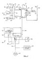
- Figure 1 is a schematic view of the molding station and mold clamping apparatus of an injection molding machine, showing the mold halves and the associated mold traversing and clamping system in accordance with the present invention.
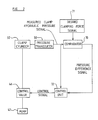
- Figure 2 is a block diagram showing the interconnection of the several parts to illustrate the control arrangement in accordance with the present invention.
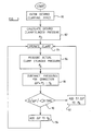
- Figure 3 is a flow chart showing the overall operation of the clamp force maintenance arrangement in accordance with the present invention.
- Referring now to the drawings, and particularly to Figure 1 thereof, there is shown the mold supporting and
clamping system 10 of an injection molding machine for molding plastics parts. Astationary platen 12 is carried by a base (not shown) and securely supports a first, stationary mold half 14.Stationary platen 12 also supports a pair ofrapid traverse cylinders 16 within whichrespective pistons 18 are movable and from whichrespective piston rods 20 extend in an outward direction beyond stationary mold half 14. Amovable platen 22 is positioned opposite and facingstationary platen 12 and carries a second,movable mold half 24 onface 26 thereof. Moldhalf 24 is adapted to engage with stationary mold half 14 to define therebetween one or more mold cavities (not shown).Movable platen 22 is slidably carried on a plurality of spaced, parallel tie rods (not shown) that can be connected tostationary platen 12 to extend outwardly therefrom toward and beyondmovable platen 22, so thatmovable platen 22 can be moved toward and away fromstationary platen 12.Piston rods 20 ofrapid traverse cylinders 16 are connected withmovable platen 22, and the cylinders are adapted to quickly movemovable platen 22 either toward or away fromstationary platen 12 during the operating cycle of the machine. - Extending from
opposite face 28 ofmovable platen 22 is aclamp piston 30 that is slidably carried in a sleeve-like clamp cylinder 32 that has anopen end 34 and a closedend 36.Open end 34 facesmovable platen 22 and closedend 36 includes aflow control valve 38, commonly referred to as a prefill valve, that is adapted to permit the flow of hydraulic fluid into and out of the clamp cylinder from and to reservoir 40. The purpose ofvalve 38 will be described hereinafter. - Pressurizing fluid for
clamp cylinder 32 is obtained from a pressurizing system that includes anhydraulic pump 42, the output of which is conveyed through apump conduit 44 to a secondflow control valve 46 and then throughclamp cylinder conduit 48. Preferably,flow control valve 46 is a zero-leakage, cartridge-type valve that tightly seals the fluid pathway betweenpump conduit 44 andclamp cylinder conduit 48 to minimize leakage from the clamp cylinder and thereby maintain the desired hydraulic pressure level in the clamp cylinder. Apressure transducer 50 is provided inclamp cylinder conduit 48 to sense the hydraulic pressure withinclamp cylinder 32 and to provide an output signal representative of that hydraulic pressure. - The output of
pump 42 can also be in communication with anothersystem 52, which is designated schematically in the drawing, and which can be, for example, the injection system or any other system of the machine in which hydraulic fluid under pressure is required during thetime valve 46 is closed. - As shown,
valve 46 is in the form of an assembly that includes a directionalflow control valve 54, acover cartridge 56, and acartridge valve 58, and can be a commercially available valve structure that is obtainable from Rexroth Corp., of Bethelhem, Pennsylvania. Although a particular type of cartridge valve structure has been illustrated and described, it will be apparent to those skilled in the art that other types of valves can be provided, if desired, to perform the same function as that of the cartridge valve structure disclosed herein. - The pressure transducer can be of any convenient and suitable type, such as, for example, a strain gage-type transducer, a piezoelectric transducer, or the like. A suitable pressure transducer can be obtained from Dynisco Inc., of Norwood, Massachusetts.
- The source of the plasticated material that is injected into the mold cavity is the injection system, of which only a fragmentary representation of an
injection barrel 60 is shown in Figure 1.Injection barrel 60 is positioned on the opposite side ofstationary platen 12 from that on which stationary mold half 14 is secured, and it includes an outlet that communicates with a passageway (not shown) that extends throughstationary platen 12 and stationary mold half 14 to communicate with the mold cavity. - The clamping system shown operates from an initial position in which
mold halves halves rapid traverse cylinders 16, which causesmovable platen 22, along withmovable mold half 24, to travel along the tie rods (not shown) towardstationary platen 12 and stationary mold half 14. The direction of movement is from right to left as viewed in Figure 1, and the position of the parts as illustrated in Figure 1 shows themold halves - As
movable platen 22 moves from right to left,clamp piston 30, which is secured thereto, moves along with it, outwardly fromclamp cylinder 32 and in a direction away fromprefill valve 38. During the outward movement ofpiston 30 fromcylinder 32,prefill valve 38 is opened so that hydraulic fluid from reservoir 40 can flow through the prefill valve to occupy the space vacated by the outwardly moving piston and thereby fill the increasing volume of the clamp cylinder with hydraulic fluid. Such an operation eliminates the need to provide a high volume pump to fill the large volume vacated by the outwardly moving clamp piston. - When
movable platen 22 has reached substantially its furthest position relative toclamp cylinder 32, and is in the position shown in Figure 1, at whichpoint mold halves 14 and 24 are substantially in contacting engagement,prefill valve 38 is closed,valve 46 is opened, andpump 42 is energized to provide pressurized hydraulic fluid throughpump conduit 44,valve 46, andclamp cylinder conduit 48 in order to impose pressure on the hydraulic fluid within the clamp cylinder, and thereby provide a clamping force to hold the two mold halves together while high pressure plasticated material is being injected into the mold cavity. When the desired hydraulic pressure has been reached in the clamp cylinder, to provide the desired clamping force,valve 46 can be closed by a control signal provided by a control system, which will be hereinafter described. Whenvalve 46 is closed, the fact that substantially no leakage occurs through the valve means that the pressure withinclamp cylinder 32 is maintained until the hydraulic pressure inclamp cylinder 32 is released by asuitable decompression valve 39, which can be, for example, a pilot operated counterbalance valve to control the rate of release of the hydraulic pressure in the clamp cylinder. Likewise, during the time the clamping force is being maintained,pump 42 is not needed for maintaining the clamping force, and consequently the pump can either be shut down, or its output diverted to another system, such as, for example, theinjection system 52, which comes into play while the clamping force is being maintained on the mold halves. After the plasticated material has been injected into the mold cavity the mold halves are maintained together for a short period of time while the plasticated material in the mold cavity is allowed to cool and solidify. At a predetermined time after injection has taken place, the pressure maintained inclamp cylinder 32 byvalve 46 is released by openingdecompression valve 39, after which prefillvalve 38 is opened, andrapid traverse cylinders 16 are activated by providing pressurized hydraulic fluid at the head end of each ofcylinders 16 to force the platens and mold halves apart, and to shiftmovable platen 22 towardclamp cylinder 32 in order to permit the molded article to be removed from the mold cavity. After removal of the molded part the cycle is repeated. -
Pressure transducer 50 senses the hydraulic pressure withinclamp cylinder 32 and can be used to provide an output signal when the desired hydraulic pressure is reached. However, because of time delays in the system, including the time required to actuatevalve 46 to move the valve spool from an open to a closed condition, in practical effect the hydraulic pressure within the clamp cylinder continues to rise to a level above the desired pressure as a result of overshoot resulting from those time delays. Unless a correction is made to account for the overshoot, the hydraulic pressure, and consequently the clamping force, will be higher than the desired value, which could cause damage to the mold halves, and possibly also to the injection molding machine, if the pressure were excessively high. - In order to eliminate the effect of the overshoot in clamp cylinder hydraulic pressure resulting from the time delays in the hydraulic system, the present invention provides a control arrangement for correcting for the overshoot in a given operating cycle by applying a correction factor during the subsequent operating cycle in order to provide a clamp cylinder hydraulic pressure that results in the desired clamping force between the mold halves.
- Referring now to Figure 2, pump 42 operates through
control valve 46 to provide pressurized hydraulic fluid to clampcylinder 32. The pressure withinclamp cylinder 32 is sensed bypressure transducer 50, which provides an output signal representative of the clamp cylinder hydraulic pressure. The output signal changes in magnitude as the hydraulic pressure within clamp cylinder builds up as a result of the operation ofpump 42, and when the desired pressure level is reachedcontrol valve 46 is closed. However, because of the time delays in the hydraulic system, resulting in overshoot of the pressure in the clamp cylinder, the steady-state pressure value in the clamp cylinder during the clamping phase of the cycle is higher than the desired pressure. The output signal corresponding with that steady-state value is provided to acomparator 70, into which the desired clamping force signal is also entered. The desired clamping force signal can be converted within the comparator to a pressure value by dividing the clamping force by the transverse cross-sectional area of the clamping piston against which the hydraulic pressure acts.Comparator 70 compares the pressure value corresponding with the desired clamping force with the measured steady-state clamp cylinder hydraulic pressure, which is in the form of the steady-state output signal from the pressure transducer, and subtracts that measured clamp hydraulic pressure from the desired hydraulic pressure to provide a pressure difference signal. The pressure difference signal is provided as an input to acontrol unit 72 that subsequently provides an output control signal that is representative of a new pressure level for use in the next succeeding clamp operating cycle to closecontrol valve 46 at the proper part of the next succeeding clamp operating cycle. In that next cycle the clamp hydraulic pressure is continuously monitored by the pressure transducer, and when the new pressure level is reached the control unit sends a control signal to close the control valve. - The control signal from the control unit is the algebraic sum of the steady-state clamp hydraulic pressure as measured during the preceding cycle and the pressure difference signal based upon the operation of the clamp system during that preceding cycle. In that connection, the pressure difference signal can be either a positive or a negative quantity, depending upon the measured steady-state clamp hydraulic pressure in the initial operating cycle.
- After a desired mold clamping time has elapsed, a suitable control signal is applied to
decompression valve 39 to thereby release the pressure inclamp cylinder 32, whereupon the prefill valve is opened and the clamp piston is again retracted into the clamp cylinder. - During the next succeeding cycle, the pressurized fluid provided by
pump 42 increases the hydraulic pressure level within the clamping cylinder, andpressure transducer 50 provides an output signal indicative of that changing pressure level to controlunit 72. When the pressure transducer output signal reaches the pressure level that corresponds with a new pressure level based upon the sum of the measured steady-state clamp hydraulic pressure of the preceding cycle plus the pressure difference signal for that preceding cycle,control unit 72 provides a control signal to closecontrol valve 46 in order to attempt to obtain a corrected hydraulic pressure withinclamp cylinder 32. Several operating cycles may be necessary before the desired clamping force is achieved. - Essentially, then, the control arrangement in accordance with the present invention operates to sense operating parameters to determine the difference between the actual clamping force relative to the desired clamping force during a given clamp operating cycle, and then provides a correction signal to attempt to control the operation of the control valve so that the valve is closed either earlier or later than it had been closed in the preceding cycle, in order to correct the clamping force during the next operating cycle by either reducing the hydraulic pressure in the clamp cylinder or by increasing it.
- The control arrangement illustrated in Figure 2 can be achieved by separate components that provide the particular functions illustrated and described. Additionally, however, if desired a microprocessor can be provided to perform the functions of the comparator and the control unit as hereinbefore described.
- Referring now to Figure 3, there is shown a flow chart for the preferred embodiment of the invention and illustrating the various steps to provide the desired hydraulic pressure in the clamping cylinder. The system is started by entering a desired clamping force signal at
step 80. The desired clamping force is determined by the machine user and is usually based upon the injection pressure to be utilized to inject the plasticated material into the mold and the projected area of the mold cavity over which that pressure will act. The desired hydraulic pressure that corresponds with the desired clamping force is calculated atstep 82, based upon the cross-sectional area of the clamping piston, to provide a set point or desired pressure value PD. The clamp is then operated through an operating cycle,step 84, in which the control unit closes the control valve when the desired pressure PD is reached, as sensed by the pressure transducer. However, because of the time delays within the system, the actual steady-state clamping pressure within the clamping cylinder is usually greater than the desired pressure by virtue of the overshoot of the pressure level resulting from time delays in the hydraulic system. Similarly, if some condition occurred that caused the valve to close earlier than desired, the actual hydraulic pressure within the cylinder would be less than the desired value. In either instance, the pressure transducer senses the hydraulic pressure within the clamping cylinder, and after the control valve has closed and the pressure within the clamp cylinder has reached a steady-state value, that steady-state value is considered instep 86 to be the actual hydraulic clamping pressure PA within the clamping cylinder. That actual hydraulic clamping pressure PA is compared with the desired hydraulic clamping pressure PD, and if the two pressures are different the actual pressure is subtracted from the desired pressure instep 88 to provide a pressure difference signal P. - The magnitude of the pressure difference determined in
step 88 affects the amount of pressure level correction that is used to set the clamp hydraulic pressure control signal to be provided in the next succeeding operating cycle. If it is determined instep 90 that the absolute value of the pressure difference P is less than a predetermined value, which, for example, can be selected to be 30 tons for an injection molding machine having a clamp system providing a maximum clamping force of 250 tons, then only a portion of that pressure difference is applied as a correction during the next succeeding cycle. As shown in Figure 3, the additive portion is preferably limited to 10% of the pressure difference, although other percentages could also be selected, and that additive portion is added instep 92 to the actual steady-state hydraulic clamping pressure for that cycle to provide a new hydraulic clamp pressure value at which controlvalve 46 is closed during the next succeeding cycle. Thus,control valve 46 is closed in the succeeding operating cycle when the clamp hydraulic pressure sensed by the pressure transducer corresponds with the value that results from adding 10% of the pressure difference in the preceding cycle to the steady-state clamp hydraulic pressure that was sensed during the clamp pressure maintenance phase of that preceding operating cycle. As shown in Figure 3, the correction process continues until the actual and the desired hydraulic clamping pressures are substantially equal. - If the determination in
step 90 of the absolute value of the pressure difference reveals that the pressure difference is greater than the predetermined value, which, for example, can be 30 tons, then the control unit causes a greater change to occur in the new hydraulic clamp pressure value for the next succeeding cycle by adding, instep 94, the entire pressure difference determined instep 88 to the steady-state hydraulic clamping pressure that was obtained in the preceding cycle instep 86, in order to more rapidly reach the desired clamping force. The system then continuously monitors the clamp cylinder hydraulic pressure and makes appropriate changes to maintain it in substantial conformity with the desired pressure to achieve the desired clamping force. - It can thus be seen that the present invention provides a distinct improvement over the previous arrangements for maintaining hydraulic clamping pressure in the clamping system of an injection molding machine.
- Although particular embodiments of the present invention have been illustrated and described, it will be apparent to those skilled in the art that various changes and modifications can be made without departing from the spirit of the present invention. Accordingly, it is intended to encompass within the appended claims all such changes and modifications that fall within the scope of the present invention.
Claims (10)
Applications Claiming Priority (2)
| Application Number | Priority Date | Filing Date | Title |
|---|---|---|---|
| US265709 | 1988-11-01 | ||
| US07/265,709 US4942004A (en) | 1988-11-01 | 1988-11-01 | Method and apparatus for regulating mold clamping force in an injection molding machine |
Publications (2)
| Publication Number | Publication Date |
|---|---|
| EP0367139A2 true EP0367139A2 (en) | 1990-05-09 |
| EP0367139A3 EP0367139A3 (en) | 1991-04-17 |
Family
ID=23011573
Family Applications (1)
| Application Number | Title | Priority Date | Filing Date |
|---|---|---|---|
| EP19890119989 Withdrawn EP0367139A3 (en) | 1988-11-01 | 1989-10-27 | Injection moulding machine and method of regulating the clamping force of an injection moulding machine |
Country Status (5)
| Country | Link |
|---|---|
| US (1) | US4942004A (en) |
| EP (1) | EP0367139A3 (en) |
| JP (1) | JPH02198818A (en) |
| CA (1) | CA2000852A1 (en) |
| DE (1) | DE367139T1 (en) |
Cited By (2)
| Publication number | Priority date | Publication date | Assignee | Title |
|---|---|---|---|---|
| EP0947305A3 (en) * | 1998-03-16 | 2002-12-11 | Husky Injection Molding Systems Ltd. | Injection mold clamp pressure optimization system and method |
| EP3331049A4 (en) * | 2016-04-15 | 2018-06-13 | LG Chem, Ltd. | Apparatus and method for molding pouch exterior material for secondary battery |
Families Citing this family (31)
| Publication number | Priority date | Publication date | Assignee | Title |
|---|---|---|---|---|
| JP2736757B2 (en) * | 1995-03-16 | 1998-04-02 | 日精樹脂工業株式会社 | Mold clamping force control method for injection molding machine |
| JP3247319B2 (en) * | 1997-08-26 | 2002-01-15 | 株式会社名機製作所 | Method and device for controlling clamping pressure in direct pressure type clamping device |
| US7775966B2 (en) | 2005-02-24 | 2010-08-17 | Ethicon Endo-Surgery, Inc. | Non-invasive pressure measurement in a fluid adjustable restrictive device |
| US8066629B2 (en) | 2005-02-24 | 2011-11-29 | Ethicon Endo-Surgery, Inc. | Apparatus for adjustment and sensing of gastric band pressure |
| US8016744B2 (en) | 2005-02-24 | 2011-09-13 | Ethicon Endo-Surgery, Inc. | External pressure-based gastric band adjustment system and method |
| US7699770B2 (en) | 2005-02-24 | 2010-04-20 | Ethicon Endo-Surgery, Inc. | Device for non-invasive measurement of fluid pressure in an adjustable restriction device |
| US7927270B2 (en) | 2005-02-24 | 2011-04-19 | Ethicon Endo-Surgery, Inc. | External mechanical pressure sensor for gastric band pressure measurements |
| US7775215B2 (en) | 2005-02-24 | 2010-08-17 | Ethicon Endo-Surgery, Inc. | System and method for determining implanted device positioning and obtaining pressure data |
| US7658196B2 (en) | 2005-02-24 | 2010-02-09 | Ethicon Endo-Surgery, Inc. | System and method for determining implanted device orientation |
| JP4445411B2 (en) * | 2005-03-01 | 2010-04-07 | 日精樹脂工業株式会社 | Method for correcting mold clamping force of mold clamping device |
| US8870742B2 (en) | 2006-04-06 | 2014-10-28 | Ethicon Endo-Surgery, Inc. | GUI for an implantable restriction device and a data logger |
| US8152710B2 (en) | 2006-04-06 | 2012-04-10 | Ethicon Endo-Surgery, Inc. | Physiological parameter analysis for an implantable restriction device and a data logger |
| US8187163B2 (en) | 2007-12-10 | 2012-05-29 | Ethicon Endo-Surgery, Inc. | Methods for implanting a gastric restriction device |
| US8100870B2 (en) | 2007-12-14 | 2012-01-24 | Ethicon Endo-Surgery, Inc. | Adjustable height gastric restriction devices and methods |
| US8142452B2 (en) | 2007-12-27 | 2012-03-27 | Ethicon Endo-Surgery, Inc. | Controlling pressure in adjustable restriction devices |
| US8377079B2 (en) | 2007-12-27 | 2013-02-19 | Ethicon Endo-Surgery, Inc. | Constant force mechanisms for regulating restriction devices |
| US8192350B2 (en) | 2008-01-28 | 2012-06-05 | Ethicon Endo-Surgery, Inc. | Methods and devices for measuring impedance in a gastric restriction system |
| US8337389B2 (en) | 2008-01-28 | 2012-12-25 | Ethicon Endo-Surgery, Inc. | Methods and devices for diagnosing performance of a gastric restriction system |
| US8591395B2 (en) | 2008-01-28 | 2013-11-26 | Ethicon Endo-Surgery, Inc. | Gastric restriction device data handling devices and methods |
| US7844342B2 (en) | 2008-02-07 | 2010-11-30 | Ethicon Endo-Surgery, Inc. | Powering implantable restriction systems using light |
| US8221439B2 (en) | 2008-02-07 | 2012-07-17 | Ethicon Endo-Surgery, Inc. | Powering implantable restriction systems using kinetic motion |
| US8114345B2 (en) | 2008-02-08 | 2012-02-14 | Ethicon Endo-Surgery, Inc. | System and method of sterilizing an implantable medical device |
| US8057492B2 (en) | 2008-02-12 | 2011-11-15 | Ethicon Endo-Surgery, Inc. | Automatically adjusting band system with MEMS pump |
| US8591532B2 (en) | 2008-02-12 | 2013-11-26 | Ethicon Endo-Sugery, Inc. | Automatically adjusting band system |
| US8034065B2 (en) | 2008-02-26 | 2011-10-11 | Ethicon Endo-Surgery, Inc. | Controlling pressure in adjustable restriction devices |
| US8233995B2 (en) | 2008-03-06 | 2012-07-31 | Ethicon Endo-Surgery, Inc. | System and method of aligning an implantable antenna |
| US8187162B2 (en) | 2008-03-06 | 2012-05-29 | Ethicon Endo-Surgery, Inc. | Reorientation port |
| JP4805994B2 (en) * | 2008-11-06 | 2011-11-02 | 日精樹脂工業株式会社 | Mold clamping force setting method for injection molding machine |
| JP4970406B2 (en) * | 2008-11-06 | 2012-07-04 | 日精樹脂工業株式会社 | Mold clamping force setting method for injection molding machine |
| US8346442B2 (en) * | 2010-03-22 | 2013-01-01 | Cnh Canada, Ltd. | System and method for determining ground engaging tool position based on fluid pressure |
| CN112326231B (en) * | 2020-11-07 | 2022-12-02 | 浙江科科检测科技有限公司 | Valve detection method and detection equipment |
Family Cites Families (18)
| Publication number | Priority date | Publication date | Assignee | Title |
|---|---|---|---|---|
| US2790204A (en) * | 1955-05-24 | 1957-04-30 | Eastman Kodak Co | Injection molding machine with stress control system |
| GB1002569A (en) * | 1962-06-13 | 1965-08-25 | David Theodore Nelson Williams | Improvements in or relating to hydraulic control systems |
| DE1558277A1 (en) * | 1967-07-26 | 1970-03-19 | Mahle Werk Gmbh | Device for regulating the closing pressure of mold holding presses for die casting machines operated by toggle levers |
| US3579741A (en) * | 1968-11-04 | 1971-05-25 | Lester Engineering Co | Machine and clamp force control system therefor |
| NL7207024A (en) * | 1972-05-25 | 1973-11-27 | ||
| US3939329A (en) * | 1974-08-26 | 1976-02-17 | Gte Sylvania Incorporated | Interface means |
| US3940930A (en) * | 1975-01-20 | 1976-03-02 | Package Machinery Company | Hydraulic system for injection molding machine |
| DE2514009C3 (en) * | 1975-03-29 | 1981-03-12 | Robert Bosch Gmbh, 7000 Stuttgart | Plastic injection molding machine with a control device for regulating the hydraulic pressure acting on a plasticizing and injection screw |
| DE2825795C2 (en) * | 1978-06-13 | 1982-06-03 | Werner & Pfleiderer, 7000 Stuttgart | Method for building up pressure in a press and switching arrangement for carrying out the method |
| US4281977A (en) * | 1979-10-01 | 1981-08-04 | Package Machinery Company | Apparatus for setting a clamping load |
| US4269580A (en) * | 1980-06-11 | 1981-05-26 | General Motors Corporation | Compression molding press with hydraulic controls |
| SE432221B (en) * | 1980-06-30 | 1984-03-26 | Karlstad Mekaniska Ab | DEVICE FOR COMBINED MEDICAL AND SPEED CONTROL OF A HYDRAULIC MANOVERED PRESS TABLE |
| US4370116A (en) * | 1981-10-13 | 1983-01-25 | Package Machinery Company | Tonnage indicator for injection molding machine |
| DE3223720A1 (en) * | 1982-06-25 | 1983-12-29 | Robert Bosch Gmbh, 7000 Stuttgart | Device for actuating a closing cylinder of a plastic injection-moulding machine |
| JPS60139420A (en) * | 1983-12-28 | 1985-07-24 | Fanuc Ltd | Die opening-closing speed controller |
| JPS61114834A (en) * | 1984-11-09 | 1986-06-02 | Fanuc Ltd | System of protecting mold of injection molding machine using servomotor |
| JPH0635036B2 (en) * | 1985-02-20 | 1994-05-11 | 株式会社日本製鋼所 | Mold opening and closing control device for injection molding machine |
| JPH01206018A (en) * | 1988-02-12 | 1989-08-18 | Komatsu Ltd | Oil hydraulic control circuit of injection molder |
-
1988
- 1988-11-01 US US07/265,709 patent/US4942004A/en not_active Expired - Lifetime
-
1989
- 1989-10-17 CA CA002000852A patent/CA2000852A1/en not_active Abandoned
- 1989-10-27 EP EP19890119989 patent/EP0367139A3/en not_active Withdrawn
- 1989-10-27 DE DE198989119989T patent/DE367139T1/en active Pending
- 1989-11-01 JP JP1285984A patent/JPH02198818A/en active Pending
Cited By (3)
| Publication number | Priority date | Publication date | Assignee | Title |
|---|---|---|---|---|
| EP0947305A3 (en) * | 1998-03-16 | 2002-12-11 | Husky Injection Molding Systems Ltd. | Injection mold clamp pressure optimization system and method |
| EP3331049A4 (en) * | 2016-04-15 | 2018-06-13 | LG Chem, Ltd. | Apparatus and method for molding pouch exterior material for secondary battery |
| US10933575B2 (en) | 2016-04-15 | 2021-03-02 | Lg Chem, Ltd. | Apparatus and method for forming pouch case for secondary battery |
Also Published As
| Publication number | Publication date |
|---|---|
| US4942004A (en) | 1990-07-17 |
| CA2000852A1 (en) | 1990-05-01 |
| JPH02198818A (en) | 1990-08-07 |
| DE367139T1 (en) | 1990-09-27 |
| EP0367139A3 (en) | 1991-04-17 |
Similar Documents
| Publication | Publication Date | Title |
|---|---|---|
| US4942004A (en) | Method and apparatus for regulating mold clamping force in an injection molding machine | |
| US5902525A (en) | Method of molding a plastic article including injecting based upon a pressure-dominated control algorithm after detecting an indicia of a decrease in the surface area of the melt front | |
| CA1116365A (en) | Sensing system and method for plastic injection molding | |
| US5853630A (en) | Low pressure method for injection molding a plastic article | |
| US4917840A (en) | Mold compression control process for an injection molding machine and apparatus thereof | |
| EP0365684B1 (en) | Molding method and molding apparatus by use of injection-compression molding machine | |
| EP0947305B1 (en) | Injection mold clamp pressure optimization system and method | |
| US5043129A (en) | Hold-pressure control and clamping in stacked multi-parting molding system having desynchronized injection periods | |
| US20030122272A1 (en) | Method and apparatus for injection molding | |
| US5814251A (en) | Molding method of injection molding machine | |
| EP0370050B1 (en) | Hold-pressure control and clamping in stacked multi-parting molding system having desynchronized injection periods | |
| US5052468A (en) | Method and apparatus for die casting shot control | |
| WO1990003878A1 (en) | Hold pressurization by confining runner systems of adjustable feed system in multiple reciprocal stack molding system | |
| US4735760A (en) | Method and apparatus for controlling injection step of injection molding machines | |
| JP3860895B2 (en) | Mold clamping control device and mold clamping control method for compression molding machine | |
| EP0630731A1 (en) | Method for molding a plastic article using a multi-point volume control system | |
| JPH0622832B2 (en) | Injection compression molding method and apparatus | |
| JP2623414B2 (en) | Toggle type clamping force abnormality detection method and apparatus | |
| DE4200163A1 (en) | Automatic regulating system for injection mould closure pressure - has controller which regulates curve of mould closure pressure against time according to corresponding curve of internal mould pressure | |
| JPH049652B2 (en) | ||
| JPH02204017A (en) | Method and apparatus for controlling injection molder | |
| JP3297343B2 (en) | Injection compression molding method | |
| JP3284099B2 (en) | Control method of mold clamping device | |
| JP3149803B2 (en) | Mold clamping device of injection molding machine | |
| JPH0134775B2 (en) |
Legal Events
| Date | Code | Title | Description |
|---|---|---|---|
| PUAI | Public reference made under article 153(3) epc to a published international application that has entered the european phase |
Free format text: ORIGINAL CODE: 0009012 |
|
| AK | Designated contracting states |
Kind code of ref document: A2 Designated state(s): AT DE FR GB |
|
| EL | Fr: translation of claims filed | ||
| TCAT | At: translation of patent claims filed | ||
| DET | De: translation of patent claims | ||
| PUAL | Search report despatched |
Free format text: ORIGINAL CODE: 0009013 |
|
| AK | Designated contracting states |
Kind code of ref document: A3 Designated state(s): AT DE FR GB |
|
| 17P | Request for examination filed |
Effective date: 19910805 |
|
| 17Q | First examination report despatched |
Effective date: 19930222 |
|
| STAA | Information on the status of an ep patent application or granted ep patent |
Free format text: STATUS: THE APPLICATION IS DEEMED TO BE WITHDRAWN |
|
| 18D | Application deemed to be withdrawn |
Effective date: 19930706 |